1
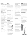
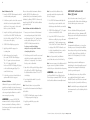
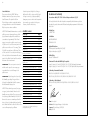
G‑TECTA™ 4GP Portable Multi-Gas Detection Instrument EN Operating Manual 2 3 Contents Safety and Warning information 3 Instructions – specific for use in hazardous areas 3 Introduction 4 Sensors 4 Key Features 5 Software 5 Batteries 5, 6, 10, 11 Product Features 6 Switching on 6 Auto Zero 6 Switching off 7 Instrument Storage 7 Normal Operation and Confidence Signals 7 Screen Icons 7 Display Symbols 7 Alarms 8 Whilst The Linde Group has made every effort to ensure that the details and information given in both our printed and online publications are accurate at the time of issue, full technical specifications are not necessarily included. Furthermore The Linde Group policy is one of continuous improvement and the right is reserved to alter details and information as the need arises. Accordingly the Customer should check any details and information they wish to rely on with The Linde Group at the time of purchase. The Linde Group can not accept liability in respect of any errors or omissions herein contained or for any loss or damage malfunction or consequential lost arising from reliance upon our publication. The customer will be responsible for any risk to health or safety from goods in the Customer’s possession and/or control. The Customer’s attention is drawn to the fact that statutory regulations and recognised codes of practice exist covering the use and handling of some goods (including safety products.) The Customer must ensure that persons who use the goods receive adequate training and safety literature. Safety and Warning information WARNING Read and understand all instructions in the operation section of this operating manual before use. WARNING Do not substitute components as this may impair intrinsic safety and invalidate warranty. WARNING Observe all warnings and instructions marked on the instrument and within this operating manual. WARNING Observe site health and safety procedures for gases being monitored and evacuation procedures. WARNING Make sure you understand the alarm warnings. WARNING If this product is not working properly, 14, 17 G-TECTA 4GP Instrument with Ozone Sensor 15 WARNING Ensure maintenance and calibrations PC Interface and PC Software 16 Product Specification 17 are carried out in accordance with the procedures in the operating manual. Accessories 18 Troubleshooting 19 Sensor Limitations 20 Available Sensors 20 Declaration of Conformity 21 The Linde Group Warranty 22 10 Wearing the Instrument 11 Gas Sampling 12 Maintenance, Calibration and Gas Testing 13 Gas Test/Calibration Troubleshooting WARNING Only charge batteries in safe (non-hazardous) areas. Instructions – specific for use in hazardous areas The following instructions apply to equipment covered by certificate numbers IECEx BAS 09.0118 and Baseefa09ATEX0246. The following information covers all relevant points listed in clause 1.0.6 of the Essential Health & Safety Requirements of the ATEX directive. 1. The certification marking is as follows: read the operating manual or call The Linde Group. WARNING The accuracy of G-TECTA™ 4GP instruments equipped with toxic gas sensor(s) should be checked periodically with known concentration calibration gas. Failure to check accuracy can lead to inaccurate and potentially dangerous readings. G-TECTA™ 4GP instruments equipped with an oxygen sensor should be periodically calibrated in fresh air. Data & Event Logging WARNING Ensure only qualified service personnel change sensors, batteries and operating system. WARNING The equipment is not certified for use in atmospheres containing more than 21% oxygen. WARNING G-TECTA™ 4GP portable gas detectors have been designed for the detection of either oxygen deficiencies or specific toxic gas accumulations. An alarm condition indicates the presence of a potentially life threatening hazard and should be taken very seriously. Replaceable Battery Rechargeable Battery 2.The G-TECTA™ 4GP may be used in Zones 1 and 2 with Groups IIA, IIB, and IIC flammable gases and vapours for Temperature Classes T1, T2, T3 and T4 (rechargeable versions) and Temperature Classes T1, T2 and T3 (replaceable battery versions). 4 3.The equipment is certified for use in ambient temperatures in the range –20°C to +55°C (-4 to +131 F). The equipment should not be used outside these temperature ranges. Toxic and Oxygen sensors are not rated for continuous operation at high temperatures greater than 40°C (104°F). 4.Compliance with Essential Health and Safety Requirements has been assured by compliance with EN60079-0; EN60079-1; EN60079-11 as certified by Baseefa. Compliance with gas detection performance standards EN50054; EN50057; EN61779-1; EN61779-4; EN50104 has been certified by Lloyd’s Register. EMC compliance to EN50270 has been certified by 3C Test Ltd. 5.Repair of this equipment and gas sensor replacement shall be carried out by the manufacturer or approved service centre in accordance with the applicable code of practice. 6.If the equipment is likely to come into contact with aggressive substances, then it is the responsibility of the user to take suitable precautions that prevent it from being adversely affected, thus ensuring that the type of protection is not compromised. 7.The rechargeable battery must only be charged in non-hazardous (safe) areas by connection to the specified Linde charger. Rechargeable batteries can only be replaced by a Linde Group Authorised Service Centre. 8.Only the following battery types may be fitted in the battery compartment of the replaceable battery pack: Duracell MN1500 (LR6), Varta 4006, Energizer LR6, GP 15A LR6 1.5V. Batteries must only be changed in a non-hazardous (safe) area. Users can only change non rechargeable batteries in G-TECTA™ 4GP instruments. 5 9.The equipment is not certified for use in atmospheres containing more than 21% Oxygen. Area Classifications: Zone 1: An area classified as Zone 1 is likely to have ignitable concentrations of flammable gases, vapours or liquids present under normal operating conditions. Zone 2: An area classified as Zone 2 is not likely to have ignitable concentrations of flammable gases, vapours or liquids present under normal operating conditions. G-TECTA™ 4GP Portable Multi-Gas Detection Instrument Introduction G-TECTA™ 4GP is a premium, portable Multi-Gas Detection Instrument, designed to be carried or worn by individuals working in potentially hazardous environments such as confined spaces. The instrument is available with an internal pump or as a diffusion only instrument. G-TECTA™ 4GP is certified for use in classified hazardous areas and monitors up to four different gases by displaying the readings simultaneously on the instrument screen. Alarm warnings are transmitted by means of a loud audible alarm, a bright visual alarm of blue/red flashing LEDs and an internal vibrating alarm. Sensors G-TECTA™ 4GP can be specified with a wide range of intelligent gas sensors. The sensor is fitted to an intelligent processor which contains calibration and sensor information. The G-TECTA™ 4GP can be reconfigured at any time by replacing the precalibrated intelligent sensor(s) with alternative gas types. Sensors should be replaced by trained service personnel and are easy to fit using “plug and play” technology. The intelligent sensor(s) are immediately recognised by the instrument and are ready to use after instrument calibration. Key Features G-TECTA™ 4GP has been designed to be a reliable and robust personal monitoring system, whilst being compact, light and easy to use. The instrument is water and dust tight to IP65 rating. The G-TECTA™ 4GP’s shape and design ensures high levels of user comfort and minimal interference with the user’s normal work function. The non-slip grip and lockable attachment clip ensure secure handling and wear ability and additional accessories such as shoulder straps and chest harness allow flexible wearing options if desired. The G-TECTA™ 4GP has a single mode button and a high quality display with automatic backlight. The instrument continuously monitors the gas level in the environment providing current, peak, and time weighted average (TWA) readings for the user. The G-TECTA™ 4GP can be configured by utilising Linde G-TECTA™ PC software. Data and event logging can also be downloaded and managed through a fast and reliable optical communication link. Software The instrument software has been written in accordance with IEC 61508 to ensure quality and integrity in operation. The internal circuitry monitors for any malfunction and will display an error warning to the user in the unlikely event they occur. Batteries The G-TECTA™ 4GP Portable Multi-Gas Detector has two battery options: Li-ion rechargeable or nonrechargeable batteries. Rechargeable Batteries G-TECTA™ 4GP uses a Li-ion battery pack and should arrive with sufficient charge so that the unit can be used straight out the box. However, to attain the full operating time you should charge the battery. (The actual operating time will depend on the types of sensor installed.) The G-TECTA™ 4GP with pump is designed to operate for at least 12 hours on a fully charged battery. WARNING Only recharge the battery in a safe (non-hazardous) area and with a Linde G-TECTA™ 4GP charger. Failure to comply could invalidate safety certification and may result in permanent damage to the instrument. Non-rechargeable Batteries G-TECTA™ 4GP uses a three AA (LR6) alkaline battery pack and is designed to operate for 11 hours using new batteries. WARNING G-TECTA™ 4GP uses AA (LR6) batteries. To maintain compliance with instrument certification, ensure only the following battery types are used: GP (15A), Energiser, Duracell and Varta (4006).Nonrechargeable Batteries G-TECTA™ 4GP uses a three AA (LR6) alkaline battery pack and is designed to operate for 11 hours using new batteries. WARNING G-TECTA™ 4GP uses AA (LR6) batteries. To maintain compliance with instrument certification, ensure only the following battery types are used: GP (15A), Energiser, Duracell and Varta (4006). 6 7 G-TECTA™ 4GP – Product Features Gas Sensors The instrument will continue through a start up sequence as shown below, this will take approximately 45 seconds. Sounder Outlet G-TECTA 4GP v1.0 Alarm LEDs CAL 5 – Sep – 2009 14 : 02 : 49 5 – Sep – 2009 14 : 02 : 49 CH4 %LEL CO ppm 0.0 0 0.0 20.9 H2S ppm O2 % G-TECTA 4GP v1.0 G-TECTA 4GP v1.0 Note: The instrument will time out in 10 seconds then change to normal operating mode, without performing an auto zero, if the mode button is not pressed. AUTO ZERO? ? 7 secs ? ? ? ? ? ? ? CH4 ? ? ? %LEL CO Mode Button Note: During the start up sequence the next calibration date will be displayed. Display Operation Switching on The G-TECTA™ 4GP is designed to be very easy to operate. Please follow these simple steps to ensure your instrument is ready for use: Step 1 WARNING Ensure the instrument is in clean air. Step 2 Press and hold the mode button for approximately 2 seconds until the red LED flashes on the instrument. The display screen will light up and the instrument will begin its start up sequence. G-TECTA™ 4GP Start-Up Sequence The instrument will test the alarm LEDs, the alarm sounder, the vibration alarm and the display screen. The sounder may be silenced by pressing the mode button once. CAL 5 – Sep – 2009 14 : 02 : 49 If the calibration due date has expired, the G-TECTA™ 4GP instrument will display a warning message that calibration is due. As a default the instrument can still function, however the G-TECTA™ 4GP can be configured to automatically shut down using G-TECTA™ PC software if required. The Linde Group strongly recommends that instruments are calibrated as soon as possible once the calibration date is due. Auto Zero* The Auto Zero function is enabled as a default setting. During start-up, the instrument will display Auto Zero and “????”. Press the mode button to confirm the Auto Zero function. ? CH4 CO CH4 CO H2S O2 H2S O2 20.9 ppm O2 % Note: If Auto Zero fails, a warning message will be displayed and an X will appear against the sensor that has failed (See the Troubleshooting section if this occurs). Switching Off Press and hold the mode button for 5 seconds, the display will count down until the display shows OFF. If you release the mode button during the countdown, the G-TECTA™ 4GP will return to normal operating mode. Instrument Storage In order to optimise sensor performance and lifetime, your G-TECTA™ 4GP instrument should be stored in a safe, non-hazardous area. The area should be clean and dry, between temperature ranges 0-30°C, and at a humidity level of 20-90%RH. Normal Operation and Confidence Signals CH4 %LEL CO ppm 0.0 0 0.0 20.9 H2S ppm O2 % The instrument will display up to four gas readings and each channel will display the gas types, units and current readings. * This setting can be configured to operate automatically, on user confirmation (default), or disabled, using G-TECTA™ PC software (see page 15). Flashing icon, G-TECTA™ 4GP in normal operating mode Pump Battery ! 0 0.0 Infra-red Port ? Start Up ppm 0.0 H2S During the start up sequence, check the battery display to ensure you have enough charge to use the instrument. ? AUTO ZERO AUTO ZERO 7 secs AUTO ZERO? Screen Icons Always check the gas type being monitored by your instrument and ensure you have been trained in your site health and safety procedures. Confidence Signals To give you added confidence the instrument is operating correctly, the G-TECTA™ 4GP will (every 10 seconds): 1 Sound a short beep 2. Flash a blue LED In addition the “3” icon will flash on the display. Display Symbols Battery ! When the battery is fully charged, the battery icon will show 6 black bars. When the battery is empty, the battery icon flashes and the instrument will sound warning beeps. WARNING When the battery charge is completely empty, G-TECTA™ 4GP will switch off automatically. Internal Pump The revolving pump icon indicates that the internal pump is operating. If the pump or airway becomes blocked, the instrument will emit a warning sound and will show an error message on the display. If a warning is displayed, check the instrument, flow adaptor and sample hose are free from dirt and water and that the sample hose or probe is not kinked or blocked. Note: To re-start the instrument, press the mode button. 8 Alarm The TWA alarm for toxic gases will operate when the short-term (15 minute) or long-term (8 hour) time weighted average alarm levels are exceeded. WARNING TWA alarms cannot be cleared. TWA alarms are functional for toxic gas instruments only. Display Menu Options The G-TECTA™ 4GP menu is displayed when you press the mode button twice. There are up to 4 menu options including Zero the instrument home screen. To scroll between the different options, press the mode button once. To select the menu option you require, double click on the selected icon. When the Peak and TWA menu options are selected the relevant icon will be displayed on the screen. Peak The Peak menu option displays the highest gas level for flammable and toxic gases, or the lowest level of oxygen, since the instrument was switched on or was last reset. After 5 seconds the instrument will display Clear Peak and “????”. Press the mode button to confirm the Clear Peak function. The instrument will count down and time out in 10 seconds and change back to Peak mode if the mode button is not pressed. The Peak feature is mainly used for confined space entry checks, where the instrument is lowered into a potentially hazardous environment (instead of using a sampling hose), and also for viewing peak gas exposure at the end of a shift. 9 The TWA menu option displays the 8 hour time weighted average reading for toxic gases since the unit was last switched on. Zero The Zero menu option will reset the sensor in the instrument. When the zero function has been completed, the instrument will return to normal operating mode. WARNING Always ensure you are in fresh air when using this feature. Zeroing an instrument in a contaminated atmosphere could result in incorrect gas readings. Alarms G-TECTA™ 4GP has two instantaneous alarm level settings for each sensor – level 1 and level 2 – and two additional Time Weighted Average (TWA) alarms for toxic sensors. Alarm Signals The red and blue alarm LEDs will flash, the sounder will emit a loud, fast series of beeps and the internal vibrator alarm will activate. The display will show the gas in alarm and the alarm level. CH4 %LEL CO ppm 0.0 0 0.0 16.7 H2S ppm O2 % Alarm icon Gas example under alarm For any gas, there are normally 2 alarm levels* – these are indicated by the alarm icons: * The instrument has 2 alarm levels to give the user an indication that the gas level may be rising. If any alarm warning is indicated by the instrument the work area should be evacuated. Note: The G-TECTA 4G is set to “latch” the alarm by default. This means that the instrument will continue to alarm until the operator presses the mode button. Note: If the instrument is still in the hazardous area when the sensor is re-set, the sensor will revert to an over-range alarm. Once you have evacuated the dangerous area, press the mode button on the G-TECTA™ 4GP instrument; this will reset your G-TECTA™ 4GP to normal operating mode. If the G-TECTA™ 4GP continues to alarm, i.e. you are still in a dangerous area, pressing the button will have no effect. The G-TECTA™ 4GP can optionally be configured to force the operator to switch the instrument off and on to restart. This option is programmable with G-TECTA™ PC Software. Alarms The TWA alarm for toxic gases will operate when the short-term (15 minute) or long-term (8 hour) time weighted average alarm levels are exceeded. and display The G-TECTA™ 4G will display toxic gas levels. WARNING If the sensor power is reconnected when the unit is exposed to an over-range gas concentration there is a risk of damage to the pellistor sensor. WARNING TWA alarms are functional for toxic gas instruments only. WARNING The TWA alarms cannot be cleared. Flammable over-range alarm If flammable gas levels exceed 100% LEL, G-TECTA™ 4GP locks into alarm and displays “ ” showing an over-range condition. G-TECTA™ 4GP will temporarily cut off power to the sensor to prevent burn out, and display a progress bar for 200 seconds. Note: The alarm remains active until the instrument sensor is in normal operating mode. When the power timeout is complete, the symbol changes to “ ” and the mode button should be pressed to put the instrument back into normal operating mode. The symbol will change to an egg timer to indicate that the sensor is warming up. At the end of the warm up period and assuming the instrument is in fresh air, the sensor will revert to a numeric display. Note: All alarm configurations can be set with G-TECTA™ PC Software. WARNING Depleted oxygen levels can reduce the flammable gas reading. If oxygen levels are below safe breathing limits it should be assumed that the flammable reading is low. Instrument Settings The following instrument settings can be altered using G-TECTA™ PC Software: Alarm levels for the sensor: Level 1 and level 2 alarms can be set for each gas sensor. Alarm trigger: The alarm trigger can be set for rising levels of gas (toxic and flammable), or for falling levels of gas (oxygen deficiency monitoring). Alarm latching: Latched alarms require the operator to press the mode button to clear the alarm (default setting). The alarm can be set to be latched or unlatched. Unlatched alarms will clear automatically when the gas hazard has passed. 10 Alarm sounder mute: The G-TECTA™ 4GP sounder can be set to mute for level 1 alarms only; pressing the mode button during an alarm condition, will silence the sounder and stop the vibrating alarm. The alarm LEDs will continue to flash. Alarm sounder tone: Different distinctive tones can be selected for each alarm condition. This optional feature can assist the operator to ascertain the level of hazard. WARNING This feature should only be set following extensive instrument user training. Data & Event Logging The G-TECTA™ 4GP instrument records both gas data and events. The logs can be accessed and downloaded by using the G-TECTA™ 4GP infrared optical link. The PC requires a G-TECTA™ infrared PC interface and G-TECTA™ PC software. Data is recorded in 1 minute intervals (the intervals can be adjusted using the PC software). G-TECTA™ 4GP also records the time and date for a number of operating and diagnostic events including: • Switch on and switch off • Level 1, Level 2 and Time Weighted Average Alarms (TWA) – alarm on, alarm off and peak gas levels during the alarm • Zero, calibration and gas testing – success or failure • Flammable sensor alarms – on and off • The battery condition is logged every 15 minutes whilst the instrument is operating 11 Batteries Rechargeable Batteries The re-chargeable batteries in the G-TECTA™ 4GP are Lithium-Ion batteries. The batteries will re-charge in 6 hours when fully discharged. The battery life is 12+ hours when the instrument has 3 or more sensors and a pump installed. G-TECTA™ 4GP Battery Chargers There are 3 battery charger options for the G-TECTA™ 4GP instrument. The standard instrument has its own internal re-charger and power lead. Optional charger units include a 12V vehicle charger and a 10 instrument multi-charger. WARNING Only re-charge the rechargeable battery in a safe (non-hazardous) area and with a Linde G-TECTA™ 4GP charger. Failure to comply could invalidate safety certification and may result in permanent damage to the instrument. Charging the Batteries 1.Ensure you are in a safe (non-hazardous) area. 2.Switch off the G-TECTA™ 4GP. 3.Plug the charger power supply into a mains socket. 4.The instrument charging socket is located on the bottom of the G-TECTA™ 4GP under a small rubber seal. 5.Insert the power lead into the charging socket. When the instrument is charging, it will display a battery icon sweeping from empty to full. When the instrument is fully charged, a full battery icon will flash on the screen. When G-TECTA™ 4GP is fully charged and switched on the battery icon will show six black bars. 6.Remove the power lead from the instrument and replace the rubber seal. Note: If the G-TECTA™ 4GP is switched on during charging, the battery icon will sweep from empty to full, the instrument will take longer to charge, and the battery icon will take 20 seconds to update after disconnecting the power supply. Changing Rechargeable Batteries If you experience a noticeable reduction in battery life in the instrument, rechargeable batteries should be replaced by a Linde Group Authorised Service Centre. Note: To ensure hazardous area and instrument ingress protection certification is maintained, battery replacement should only be carried out by trained and certified personnel. Non-rechargeable Batteries G-TECTA™ 4GP uses a three AA battery pack which will give 11 hours operating time. Users may change batteries in non-rechargeable versions only. To replace the battery pack: WARNING G-TECTA™ 4GP uses 3 AA batteries. To maintain compliance with instrument certification, ensure only the following LR6 battery types are used: Energiser (MN1500), GP (15A), Duracell (MN1500), Varta (4006). Wearing G-TECTA™ 4GP Instruments G-TECTA™ 4GP is supplied with a strong and durable attachment clip. The lockable attachment clip will securely attach the instrument to a pocket, belt etc. G-TECTA™ 4GP Chest/Neck Harness The optional chest/neck harness allows the user to mount the instrument on the chest or around the neck for additional comfort. Attaching the Chest Harness Plate The chest harness plate is attached to the instrument by sliding the plate over the moulded clip at the back of the instrument. 1.Release the instrument attachment clip lock. 2. Slide the plate over the attachment clip. 3.The chest harness plate will lock into place 4. Re-lock the attachment clip. 1. Ensure you are in a safe, non-hazardous area. 2.Always switch the G-TECTA™ 4GP off before changing the battery pack. 3.Remove the bottom cover using an Allen Key and remove the battery pack from the bottom of the instrument. Belt clip lever Shoulder connectors 4. Replace the three AA batteries. 5.Reinsert the battery pack into the instrument, replace and securely fasten the back cover. Lever Waist connectors 12 13 Neck Strap Attach the strap to the top connectors and place around the neck. Adjust the length of the strap until the instrument is in a comfortable working position. Chest Harness Leave the neck strap in position. Attach the other strap to the side connectors and link around the chest. Adjust the strap lengths until the instrument is in a comfortable working position. Gas Sampling To take a sample of a gas in a confined space or where there are unknown levels of gas present using G-TECTA™ 4GP, the flow sample method can be used. Flow adapter Gas in and screw the thumbscrew until it is tightly fitted into place. 2.Attach the sampling hose onto the “gas in” nozzle. 3.The G-TECTA™ 4GP pump will draw the gas sample through the “gas in” nozzle and out through the “gas out” nozzle. 4.To remove the flow cap, unscrew the thumbscrew and lift it away from the instrument. Diffusion (Non-Pumped) Instruments A flow cap must be fitted over the sensors on the front of the instrument, a hose fitted onto the flow cap “gas in” nozzle and an aspirator bulb fitted onto the “gas out” nozzle. 1.To fit the flow cap, slide the top of the flow cap into the small recess at the top of the instrument and screw the thumbscrew until it is tightly fitted into place. 2.Attach the sampling hose onto the “gas in” nozzle. 3.Attach the aspirator bulb onto the “gas out” nozzle. Gas out Note: A flow cap and a 2 metre length of hose are included in the box with your G-TECTA™ 4GP instrument. The aspirator bulb and hose (Article Numbers ASGTAK2 or ASGTAK3) is an additional accessory. Pumped Instruments A flow cap must be fitted over the sensors on the front of the instrument and a hose fitted onto the flow cap “gas in” nozzle. 1.To fit the flow cap, slide the top of the flow cap into the small recess at the top of the instrument 4.Check the aspirator bulb is attached correctly by covering the end of the bulb and by squeezing it gently. If there are no leaks, the aspirator bulb should remain deflated for a few seconds. 5.Squeeze the aspirator bulb once per second to create a steady flow of air into the instrument. We recommend the operator squeezes the aspirator bulb at least 10 times (using the 2 metre hose supplied). Longer lengths of hose and metal probes can be purchased. For additional lengths of hose, we recommend that the aspirator bulb is squeezed once for every additional 30cm of hose to enable the gas sample to reach the sensor. Continue to squeeze the bulb for an additional 45 seconds, or until gas readings stabilise. 6.To remove the flow cap, unscrew the thumbscrew and lift it away from the instrument 4GP gas detection instruments are specially formulated, high stability long life multi-gas mixes. WARNING Manual aspirator remote sampling only provides continuous gas readings for the area in which the hose or probe is located and when the aspirator bulb is being continuously squeezed. Each time a new gas reading is required, the aspirator bulb must be squeezed a sufficient number of times to bring a fresh sample and a stabilised reading to the sensor. The G-TECTA™ 4GP instrument will determine Pass/Fail status for the gas test. Maintenance, Calibration and Gas Testing • The gas flow path is leak tight. It is important to check that the flow cap is properly fitted to the G-TECTA™ 4GP unit, the outlet hose is not restricted in any way, nor additional hose length used. Cleaning Ensure the G-TECTA™ 4GP display, operator button and sensor filter remain free from dirt build up. Regularly wipe over your G-TECTA™ 4GP unit with a damp cloth and inspect the sensor filters for dirt or damage. Gas (bump) testing The atmosphere in which G-TECTA™ 4GP instruments are used can have lasting effects on the sensors. Sensors may suffer losses in sensitivity leading to degraded performance if exposed to certain substances. The Linde Group recommends a bump test each time G-TECTA™ 4GP instruments are used or issued for use. As a minimum, a monthly bump test is required to confirm sensor operation. Test gases of known composition (compatible with the settings on the instrument sensor modules) need to be applied, to verify sensor response and alarm function. Note: Please see The Linde Group data sheet “Gas Detector Calibration Frequency” for further advice on bump testing and calibration. The Linde Group manufactures and supplies Gas Test Cylinders under numerous global product brands, including Linde, BOC, AGA, Afrox etc. The Linde Group gases supplied for use with your G-TECTA™ In order to perform successful gas tests ensure: • The gas used has the recommended gas concentration and it is within the validity date specified by The Linde Group The G-TECTA™ Gas Test Kit comprises a full gas cylinder and regulator with interconnecting hose, a gas test key (used to activate Gas Test Mode on the instrument), a flow cap to attach to the G-TECTA™ 4GP, and a vent line. The Gas Test Kit is supplied in a convenient carry case. 14 How to Perform a Gas Test 1.Ensure the G-TECTA™ 4GP instrument is switched on and in normal operating mode. 2.Fit the flow cap onto the front of the sensors and attach the hose from the regulator. Attach the outlet hose to ‘vent gas away’ – do not extend this hose, restrict or allow kinks. 3.Swipe the Gas Test Key past the display, adjacent to the LED lens. The G-TECTA™ 4GP will activate the Gas Test Mode and show “TEST” and “x” next to the sensors on the display. 4.G-TECTA™ 4GP will display a progress bar. 5.Apply the gas whilst the progress bar is counting down. 6.Wait for the progress bar to complete (40 seconds). G-TECTA™ 4GP will display a “3” or “x” against each sensor and a master “3” or “x” to indicate PASS or FAIL In the event G-TECTA™ 4GP displays FAIL, please see the troubleshooting guide (Page 17) or contact The Linde Group. 7.To abort the gas test press the mode button at any time whilst the test is in progress. Instrument Calibration Calibration of the gas sensor should be performed regularly every 6 months. Over time the accuracy of the gas sensor can drift outside of what is considered a safe range and regular calibration is essential to ensure accuracy of gas readings. WARNING The accuracy of G-TECTA™ 4GP instruments should be checked periodically with known-concentration of calibration gas. Failure to check accuracy can lead to inaccurate and potentially dangerous readings 15 There are three methods of instrument calibration available. G-TECTA™ 4GP calibration can be performed directly on each instrument (one button calibration), by utilising G-TECTA™ PC software or by using the Linde G-DOCKA™ Hub. Certified calibration gases should be used. How to Perform a One Button Calibration Test 1.Ensure you are in clean air and the instrument is in normal operating mode. Double click the mode button and select “Zero” from the options menu by double clicking on the “Zero” icon. G-TECTA™ 4GP will perform an Auto Zero. To perform a one button calibration, complete the next steps within 15 minutes of completing the Auto Zero. 2.Fit the flow cap onto the front of the sensors and attach the hose from the regulator. Attach the outlet hose to ‘vent gas away’ – do not extend this hose, restrict or allow kinks. 3.Swipe the Gas Test Key past the display, adjacent to the LED lens. The G-TECTA™ 4GP will activate the Calibration Mode and show “CAL” and “????” on the display. 4.Press the mode button within 10 seconds to confirm calibration. Note: If the mode button is not pressed within 10 seconds then the instrument mode will change to Gas Test Mode. Note: You can abort the calibration test by pressing the mode button at any time whilst the test is in progress. 7.The G-TECTA™ 4GP instrument will adjust the value on the gas sensor to match the stored calibration gas value within the sensor module. 8.G-TECTA™ 4GP will display a “3” or “x” against each sensor to indicate PASS or FAIL. 9.If any of the G-TECTA™ 4GP sensors do not calibrate successfully, the gas type will remain marked with a “x” and the warning messages “Gas Test Failed” and “Send for Calibration” will be displayed. The G-TECTA™ 4GP must be sent to a Linde Group Authorised Service centre for re-calibrating or sensor replacement. Note: Gas Test pass and fail, and calibration pass, fail and values are stored in the Event log. Note: Some sensors may not be calibration enabled. Oxygen sensors are by default not calibration enabled as they are calibrated in fresh air by zeroing. WARNING One button calibration will check for small drifts of stored calibration value. The Linde Group recommends G-TECTA™ 4GP is sent for full certified calibration at six monthly intervals. G-TECTA 4GP Instrument with Ozone (O3) Sensor Due to the reactive nature of ozone (O3) special procedures should be followed when calibrating gas detectors that incorporate an ozone sensor. Fittings For ozone calibrations all fittings and pipe work should be stainless steel, brass, aluminium or PTFE. Fittings or pipe work in other plastic materials such as Tygon must not be used. Gas flow rate It is important that the flow rate is set correctly as otherwise pressure effects may distort calibration values and prevent the gas detector from working correctly. To calibrate, the flow rate should be set between 0.8-1.0 litres/minute (0.03-0.04 cubic feet/minute) Normal safety precautions for handling ozone should always be observed along with any special instructions that accompany the calibration gas cylinder or generator being used. For calibrating the ozone sensor, the special flow cap assembly with four inlets (article number AS4GP3021) must be used. The Ozone sensor must always be at position 3, as marked on the flow cap. Note: The standard flow cap assembly supplied with the instrument must be used for calibrating the other gas sensors 5.G-TECTA™ 4GP will display a progress bar and an “x” will appear against each gas type. 6.Apply the gas whilst the progress bar is counting down. * G-TECTA™ PC Software can be downloaded free of charge from www.g-tecta.com 16 PC Interface and PC Software* G-TECTA™ PC Software gives the user access to data and event log files, printing reports, reconfiguring alarm levels, instrument operation functions, and running calibrations. G-TECTA™ 4GP can be connected to a PC by using the G-TECTA™ 4GP infrared optical link. The PC requires a G-TECTA™ infrared PC interface and G-TECTA™ PC software. Set-up 1.Install G-TECTA™ PC software and G-TECTA™ infrared interface on the PC. WARNING The infrared communications are not IrDA. Do NOT install IrDA drivers. 2.Where applicable, install USB software** (supplied in USB adaptor box) 3.Attach the infrared RS232 cable to the USB adaptor (where applicable) and to the PC 17 (iii)Check the available communications ports available again and select the new port or port 4, 5 or 6 and save your changes by clicking the save button on the bottom right of the options screen Gas Test/Calibration Troubleshooting Problem No response to gas Instrument fails gas test (iv)Close the G-TECTA™ PC software Note: If the instrument does not connect to the PC, select a different communications port and try again Instrument fails calibration 5.Switch on the G-TECTA™ 4GP instrument and align the instrument infrared port with the infrared adaptor 6.Open the G-TECTA™ PC software and using either the Wizard or the Engineer’s Form, select G-TECTA™ 4GP and upload the data from the instrument. 7.The software will allow you to access data or configure the instrument as required. Note: For more information on using the G-TECTA™ PC software, see the installed help file. 4.When using a USB adaptor to connect the instrument, follow the procedure below: (i)Before connecting the instrument, check the available communications ports available on the G-TECTA™ PC software options screen and note the ports available (ii)Switch on the G-TECTA™ 4GP instrument and align the instrument infrared port with the infrared adaptor Instrument passes gas test but will not enter calibration mode Possible Cause Gas Cylinder Empty Hose blocked or kinked Gas cylinder empty Gas cylinder out of date Hose blocked or kinked Calibration drifted Gas flow not started in time Gas cylinder empty Gas cylinder out of date Hose blocked or kinked Calibration drifted Instrument stabilisation time too short Zero not performed from options menu Instrument incorrectly configured G-TECTA™ 4GP Product Specification Dimensions Weight IP Rating (Dusts & Liquids) Operating Temperature Rating Humidity Rating Display Warm-up time period Typical response time Alarm sounders* Visible alarms Vibrating alarm Repeatability Electromagnetic Compatibility Explosion Protection Certification Approval Codes IECEx ATEX UL CSA Global USA CSA MED (Marine Equipment Directive) Safety & Operation Standards ** If the USB adaptor software does not start automatically, select UC232A, the appropriate operating system and install the driver Solution Check cylinder gauge. Replace cylinder Check hose and ensure no gas flow restriction Check cylinder gauge. Replace cylinder Check cylinder expiry date. Replace cylinder Check hose and ensure no gas flow restriction Calibrate instrument Repeat gas test. Start gas immediately Check cylinder gauge. Replace cylinder Check cylinder expiry date. Replace cylinder Check hose and ensure no gas flow restriction Calibrate instrument Reset instrument stabilisation time using G-TECTA™ PC Software Initiate zero on instrument menu Re-configure instrument. Send to Linde Group service centre 122 x 128 x 57 mm 498g (with attachment clip & 4 sensors) IP65 NEMA 4 -20°C Ta +55°C (-4°F Ta +131°F) 20-90% RH – non-condensing, continuous operation 128 x 64 Pixel with backlight Approx 45 seconds T90: 20 seconds (toxic & flammable) 10 seconds (oxygen) 94dB(A) Optional multiple alarm sounds Dual colour Blue/Red flashing LEDs Internal vibrating ±2% FSD, 6 months 2004/108/EC IECEx/ATEX/UL/CSA IECEx BAS 09.0118 BASEEFA09ATEX0246 UL913 CSA22.2, 152 IECEx II 2G Ex ia d IIC T4 Gb Rechargeable IECEx II 2G Ex ia d IIC T3 Gb Replaceable Batteries Class I Division 1, Groups A, B, C and D Class I Division 1, Groups A, B, C and D 96/98/EC (optional approval) EN50014, EN50020, EN50018, 94/9/EC EN50270, EN50271, IEC61508 * It is recommended that the sounder output is periodically tested to ensure the instrument continues to operate as specified 18 19 G-TECTA™ 4GP Accessories G-TECTA™ 4GP Troubleshooting ASGTK G-TECTA™ SG/4G/4GP Gas Test Key Problem/Error Message Possible Cause Solution ASGTSP G-TECTA™ 4G/4GP 1m Sample probe Instrument won’t switch on Battery has no charge Re-charge or replace battery ASGTTSP G-TECTA™ 4G/4GP Telescopic sample probe Mode button released too soon Press mode button until LEDs flash ASGTPF G-TECTA™ 4G/4GP In line water trap/particulate filter inc filter element Pump not operating Instrument incorrectly configured ASGTFE G-TECTA™ 4G/4GP Filter element for inline water trap Reconfigure instrument using G-TECTA™ PC Software ASGTDL6 G-TECTA™ 4G/4GP 6 m drop line No confidence beep Instrument function disabled ASGTCHS G-TECTA™ 4G/4GP Chest harness straps Reconfigure instrument using G-TECTA™ PC Software AS4GPBC12V G-TECTA™ 4GP Car Charger (12v) Gas reading on display when in clean air Instrument zero drifted Restart instrument in clean air AS4GPBCUK G-TECTA™ 4GP Wall socket charger 230V 50Hz UK Pins G-TECTA™ 4GP Wall socket charger 110V 60Hz US Pins Unstable or inaccurate gas readings Sensor failure AS4GPBCUS AS4GPBCEU G-TECTA™ 4GP Wall socket charger 230V 50Hz European Pins Do NOT use instrument Exit hazardous area immediately and return instrument for service AS4GPBCAU G-TECTA™ 4GP Wall socket charger 230V 50Hz Australia Auto Zero failure Switch off instrument and restart in clean air AS4GPBC10US G-TECTA™ 4GP 10-way multi-charger – with 90-260V in-line power supply, US Mains lead Instrument zeroed in contaminated atmosphere AS4GPBC10UK G-TECTA™ 4GP 10-way multi-charger – with 90-260V in-line power supply, UK Mains lead Alarm preventing Auto Zero Instrument zeroed in contaminated atmosphere Switch off instrument and restart in clean air AS4GPBC10EU G-TECTA™ 4GP 10-way multi-charger – with 90-260V in-line power supply, EUR Mains lead Calibration expired Calibration due date has passed Return instrument for calibration AS4GPBC10AU G-TECTA™ 4GP 10-way multi-charger – with 90-260V in-line power supply, Australia Flow fail. Clear blockage ASGTAHK2 G-TECTA™ SG/4G/4GP Aspirator bulb and 2m hose Sample hose is blocked (water or dirt) or kinked Clear blockage. Press mode button to restart pump ASGTAHK3 G-TECTA™ SG/4G/4GP Aspirator bulb and 3m hose Re-charge or replace battery G-TECTA™ 4GP Flow cap assembly Display shows empty battery symbol Battery has no charge AS4GP3012 ASGTAH G-TECTA™ SG/4G/4GP Aspirator hose LCD too faint/dark Instrument contrast setting incorrect Adjust instrument using G-TECTA™ PC Software AS4GP3013 G-TECTA™ 4GP Harness Assembly including shoulder strap AS4GP3014 G-TECTA™ 4GP Carry Case (rechargeable version) AS4GP3015 G-TECTA™ 4GP Carry Case (non-rechargeable version) AS4GP3019 G-TECTA™ 4GP Bench holder AS4GP3020 G-TECTA™ 4GP Infrared Adaptor for PC If you experience any other issues with the operation of the G-TECTA™ 4GP instrument, please go to www.g-tecta.com or contact an Authorised Linde Group Service Centre. 20 21 Sensor Limitations The sensors used in the G-TECTA™ 4GP have limitations common to all gas sensors, and users should be aware of the points listed below. The Linde Group can advise on particular situations and suggest alternative sensors if the instrument is likely to experience extreme conditions. Persistent exposure to high levels of toxic gas will shorten the life of a toxic sensor. If the high level gas is corrosive (e.g. hydrogen sulphide), damage may occur over time to metal components. Sensors may be cross sensitive to other gases. If unsure, contact The Linde Group. G-TECTA™ 4GP flammable instruments use a catalytic pellistor gas sensor. Common with sensors of this type, instrument readings will be unreliable over concentrations of approximately 120% LEL and oxygen is necessary for catalytic sensors to operate. A ‘pellistor saver’ is used to disconnect power to the pellistor sensor in the event of “over-range” (above 100% LEL) to prevent burn out. This feature “locks out” the sensor for 200 seconds, after which a press of the mode button on the instrument will reconnect power to the pellistor. Restart should be carried out in a known clean air environment. Available Sensors WARNING If the sensor power is reconnected when the unit is exposed to an over-range gas concentration there is a risk of damage to the pellistor sensor. WARNING Depleted oxygen levels can reduce (NH2) extended range Ammonia Sensor 0-1000 ppm (SO2) Sulphur dioxide 0-20 ppm the flammable gas reading. If oxygen levels are below safe breathing limits it should be assumed that the flammable reading is low. G-TECTA™ Electrochemical gas sensors (toxic gases or oxygen), contain chemicals. Extreme levels of humidity can cause problems. The sensors are rated for an (average) ambient humidity of 20-90% R.H. However the sensors are commonly used from the tropics, to deserts, to tundra without any functional issues. Water should not be allowed to collect on the sensor as this may impede gas diffusion. Sensor Type Range (LEL) Methane 0-100% (LEL) Propane 0-100% (LEL) Pentane 0-100% (LEL) Butane 0-100% (LEL) Ethylene 0-100% (LEL) Hydrogen 0-100% (LEL) Flammable alcohols, ketones, general solvents 0-100% (O2) Oxygen Sensor 0-25% (H2S) Hydrogen Sulphide Sensor 0-100 ppm (H2S) extended range Hydrogen Sulphide Sensor 0-500 ppm (CO) Carbon Monoxide Sensor 0-500 ppm (CO) extended range Carbon Monoxide Sensor 0-1500 ppm (Cl2) Chlorine* Sensor 0-20 ppm (NH3) Ammonia Sensor 0-100 ppm (O3) Ozone* Sensor 0-1 ppm (NO2) Nitrogen Dioxide* Sensor 0-10 ppm (NO2) extended range Nitrogen Dioxide* Sensor 0-20 ppm (H2) Hydrogen Sensor 0-1000 ppm (HCN) Hydrogen Cyanide Sensor 0-25 ppm (PH3) Phosphine* Sensor 0-5 ppm (HF) Hydrogen Fluoride* Sensor 0-10 ppm (NO) Nitric Oxide Sensor 0-100 ppm (COCl2) Phosgene* Sensor 0-1 ppm (ETO) Ethylene Oxide Sensor 0-10 ppm * Reactive gases – see G-TECTA™ datasheet on gas sampling with reactive gases Declaration of Conformity In accordance with ISO/IEC 17050-1:2004 and European Directive 94/9/EC We hereby declare that on the date the product accompanied by this declaration are placed on the market, the product conforms with all technical and regulatory requirements of the directives listed below. Product Type G-TECTA™ 4GP Certification BASEEFA09ATEX0246 IECEx BAS 09.0118 Applicable Directives Electromagnetic Compatibility 2004/108/EC Explosive Atmospheres 94/9/EC Notified Body Baseefa 1180 Buxton UK Provisions of the Directive fulfilled by the product: Group II Category 2G Ex ia d IIC T4 Gb (-20°C Ta + 55°C) IP65 Rechargeable instrument Group II Category 2G Ex ia d IIC T3 Gb (-20°C Ta + 55°C) IP65 Replaceable battery instrument Conformity – Harmonised Standards EN60079-0:2006; EN60079-1:2007; EN60079-11:2007; EN50270:2006; IEC 60079-26: 2007; EN50104: 2002; EN60079-29-1:2007 Conformity – Other Standards EN61000-4-3:2006; DD ENV 50204:1999; EN61000-6-2:2001; EN61000-6-4:2001 Signed: Name: Peter Upcott Position: Global Category Manager – Safety Products Company: The Linde Group, GU2 7XY, UK Date: June 2010 22 The Linde Group Instrumentation Warranty Gas Detection Products General The Linde Group warrants gas detectors, sensors and accessories manufactured and sold by The Linde Group to be free from defects in materials and workmanship for the periods listed in the following tables. Damages to any Linde Group products that result from abuse, alteration, power fluctuations including surges and lightning strikes, incorrect voltage settings, incorrect batteries, or repair procedures not made in accordance with the product’s Operating Manual, are not covered by The Linde Group warranty. The obligation of The Linde Group under this warranty is limited to the repair or replacement of components deemed by The Linde Group Service Department to have been defective under the scope of this standard warranty. To receive consideration for warranty repair or replacement procedures, products must be returned with transportation and shipping charges prepaid to The Linde Group, or to a Linde Group Authorised Warranty Service Centre. It is necessary to obtain a return authorisation number from The Linde Group prior to shipment. THIS WARRANTY IS EXPRESSLY IN LIEU OF ANY AND ALL OTHER WARRANTIES AND REPRESENTATIONS, EXPRESS OR IMPLIED, INCLUDING BUT NOT LIMITED TO, THE WARRANTY OF FITNESS FOR A PARTICULAR PURPOSE. THE LINDE GROUP WILL NOT BE LIABLE FOR LOSS OR DAMAGE OF ANY KIND CONNECTED TO THE USE OF ITS PRODUCTS OR FAILURE OF ITS PRODUCTS TO FUNCTION OR OPERATE PROPERLY. 23 Warranty Periods for Instruments and Accessories Product Warranty period G-TECTA™ SG G-TECTA™ 4G G-TECTA™ 4GP 2 years from date of purchase G-TECTA™ SG2 2 years from date of purchase G-DOCKA™ SG2 1 year from date of purchase G-DOCKA™ Hub 2 years from date of purchase Instrument chargers/interfaces 2 years from date of purchase Battery packs, pumps and consumables 1 year from date of purchase Warranty Periods for Sensors Sensor type Warranty period Oxygen & Flammable Sensors 2 years H2S & CO Toxic Sensors 2 years All other Toxic Sensors 1 year ** Damage to combustible gas sensors by acute or chronic exposure to known sensor poisons such as volatile lead (aviation gasoline additive), hydride gases such as phosphine, and volatile silicone gases emitted from silicone caulks/ sealants, silicone rubber moulded products, laboratory glassware greases, spray lubricants, heat-transfer fluids, waxes and polishing compounds (neat or spray aerosols), mould-release agents for plastics injection-moulding operations, waterproofing formulations, vinyl and leather preservatives, and hand lotions that may contain ingredients listed as cyclomethicone, dimethicone and polymethicone (at the discretion of The Linde Group Service department) void The Linde Group’s Standard Warranty as it applies to the replacement of combustible gas sensors. Notes Australia BOC Customer Service Centre 10 Julius Avenue, North Ryde, Sydney NSW 2113 Australia Tel: 131 262 Fax: 132 427 e-mail: [email protected] www.boc.com.au New Zealand BOC Customer Service Centre 988 Great South Road, Penrose, Auckland New Zealand Tel: 0800 111 333 Fax: 0800 229 923 e-mail: [email protected] www.boc.co.nz UK BOC Customer Service Centre Priestley Road, Worsley, Manchester, M28 2UT United Kingdom Tel: 0800 111 333 Republic of Ireland: 1890 355 255 Fax: 0800 111 555 e-mail: [email protected] www.bocindustrial.co.uk or www.bocsafetyproducts.co.uk South Africa Afrox Customer Service Centre 1 Smits Street, Industries West, Germiston 1400 South Africa Tel: 0860 020202 Fax: 0860 020201 e-mail: [email protected] www.afrox.com Thailand TIG Customer Service Centre 15th Floor, Bangna Tower A 2/3 Moo 14, Bangna-Trad Road., T.Bangkaew, A.Bangplee, Samutprakarn 10540, Thailand Tel. (66-2) 338-6100 Fax. (66-2) 312-0126 Customer Service Centre : 1384 E-mail: [email protected] www.tig.co.th Canada Linde Customer Service Centre 5860 Chedworth Way, Mississauga, Ontario, L5R OA2 Canada Tel: 1-888-256-7359 Fax: 1-877-262-8955 e-mail: [email protected] www.lindecanada.com Colombia AGA Customer Service Centre Apartado Aéreo 3624 Bogotá D.C. Colombia Tel: +57/1/4254550 Fax: +57/1/4146040 e-mail: [email protected] www.aga.com.co V 1.1 2010 G-TECTA™ 4GP Operating Manual ©2010 The Linde Group. All rights reserved. No page or part of this operation manual may be reproduced in any form without written permission of the copyright owner shown above. The Linde Group reserves the right to correct typographical errors. All information is correct at time of going to print. www.g-tecta.com The Linde Group: Linde BOC AGA Afrox