1
2008
SUPPLEMENTARY
SERVICE MANUAL
YFM7FGPX
YFM7FGX
3B4-28197-E1
FOREWORD
This Supplementary Service Manual has been prepared to introduce new service and data for the
YFM7FGPX/YFM7FGX. For complete service information procedures it is necessary to use this
Supplementary Service Manual together with the following manual.
YFM7FGPW SERVICE MANUAL: 3B4-28197-E0
YFM7FGPX/YFM7FGX
SUPPLEMENTARY
SERVICE MANUAL
©2007 by Yamaha Motor Co., Ltd.
First edition, March 2007
All rights reserved.
Any reproduction or unauthorized use
without the written permission of
Yamaha Motor Co., Ltd.
is expressly prohibited.
EBS00002
NOTICE
This manual was produced by the Yamaha Motor Company primarily for use by Yamaha dealers
and their qualified mechanics. It is not possible to include all the knowledge of a mechanic in one
manual, so it is assumed that anyone who uses this book to perform maintenance and repairs on
Yamaha vehicle has a basic understanding of the mechanical ideas and the procedures of vehicle
repair. Repairs attempted by anyone without this knowledge are likely to render the vehicle unsafe
and unfit for use.
This model has been designed and manufactured to perform within certain specifications in regard
to performance and emissions. Proper service with the correct tools is necessary to ensure that the
vehicle will operate as designed. If there is any question about a service procedure, it is imperative
that you contact a Yamaha dealer for any service information changes that apply to this model. This
policy is intended to provide the customer with the most satisfaction from his vehicle and to conform
to federal environmental quality objectives.
Yamaha Motor Company, Ltd. is continually striving to improve all its models. Modifications and significant changes in specifications or procedures will be forwarded to all authorized Yamaha dealers
and will appear in future editions of this manual where applicable.
NOTE:
• This Service Manual contains information regarding periodic maintenance to the emission control
system. Please read this material carefully.
• Designs and specifications are subject to change without notice.
_
EBS00003
IMPORTANT INFORMATION
Particularly important information is distinguished in this manual by the following notations.
The Safety Alert Symbol means ATTENTION! BECOME ALERT! YOUR
SAFETY IS INVOLVED!
WARNING
CAUTION:
NOTE:
Failure to follow WARNING instructions could result in severe injury or death to
the vehicle operator, a bystander or a person checking or repairing the vehicle.
A CAUTION indicates special precautions that must be taken to avoid damage
to the vehicle.
A NOTE provides key information to make procedures easier or clearer.
EBS00004
HOW TO USE THIS MANUAL
MANUAL ORGANIZATION
This manual consists of chapters for the main categories of subjects. (See “SYMBOLS”.)
1st title 1: This is the title of the chapter with its symbol in the upper right corner of each page.
2nd title 2: This title indicates the section of the chapter and only appears on the first page of each
section. It is located in the upper left corner of the page.
3rd title 3: This title indicates a sub-section that is followed by step-by-step procedures accompanied by corresponding illustrations.
EXPLODED DIAGRAMS
To help identify parts and clarify procedure steps, there are exploded diagrams at the start of each
removal and disassembly section.
1. An easy-to-see exploded diagram 4 is provided for removal and disassembly jobs.
2. Numbers 5 are given in the order of the jobs in the exploded diagram. A number that is enclosed
by a circle indicates a disassembly step.
3. An explanation of jobs and notes is presented in an easy-to-read way by the use of symbol marks
6. The meanings of the symbol marks are given on the next page.
4. A job instruction chart 7 accompanies the exploded diagram, providing the order of jobs, names
of parts, notes in jobs, etc.
5. For jobs requiring more information, the step-by-step format supplements 8 are given in addition
to the exploded diagram and the job instruction chart.
1
EBS00006
2
GEN
INFO
SYMBOLS
The following symbols are not relevant to
every vehicle.
Symbols 1 to 0 indicate the subject of each
chapter.
SPEC
3
4
CHK
ADJ
1 General information
2 Specifications
3 Periodic checks and adjustments
4 Engine
5 Cooling system
6 Fuel injection system
7 Drive train
8 Chassis
9 Electrical
0 Troubleshooting
ENG
5
6
FI
COOL
7
8
CHAS
DRIV
9
0
–
ELEC
A
+
TRBL
SHTG
B
E
G
H
Symbols A to H indicate the following
F
A Can be serviced with engine mounted
B Filling fluid
C Lubricant
D Special tool
E Torque
F Wear limit, clearance
G Engine speed
H Electrical data (Ω, V, A)
T.
D
C
R.
I
J
G
E
M
K
N
B
Q
BF
M
O
P
M
LS
S
R
LT
Symbols I to P in the exploded diagrams
indicate the types of lubricants and lubrication
points.
L
New
I Apply engine oil
J Apply gear oil
K Apply molybdenum disulfide oil
L Apply brake fluid
M Apply wheel bearing grease
N Apply lithium-soap-based grease
O Apply molybdenum disulfide grease
P Apply silicone grease
Symbols Q to R in the exploded diagrams
indicate where to apply a locking agent Q and
when to install a new part R.
Q Apply the locking agent (LOCTITE®)
R Replace
CONTENTS
GENERAL INFORMATION ................................................................................ 1
SPECIAL TOOLS ......................................................................................... 1
SPECIFICATIONS .............................................................................................. 2
GENERAL SPECIFICATIONS ..................................................................... 2
ENGINE SPECIFICATIONS......................................................................... 4
CHASSIS SPECIFICATIONS....................................................................... 5
ELECTRICAL SPECIFICATIONS ................................................................ 6
TIGHTENING TORQUES............................................................................. 7
ENGINE TIGHTENING TORQUES ....................................................... 7
CHASSIS TIGHTENING TORQUES ..................................................... 7
CABLE ROUTING ........................................................................................ 8
PERIODIC CHECKS AND ADJUSTMENTS.................................................... 22
INTRODUCTION ........................................................................................ 22
PERIODIC MAINTENANCE CHART FOR
THE EMISSION CONTROL SYSTEM....................................................... 22
GENERAL MAINTENANCE AND LUBRICATION CHART ........................ 23
AIR FILTER CASE ..................................................................................... 25
ADJUSTING THE FRONT SHOCK ABSORBERS .............................. 26
ADJUSTING THE REAR SHOCK ABSORBERS ................................ 26
ENGINE ............................................................................................................ 28
CRANKCASE ............................................................................................. 28
TIMING CHAIN AND OIL FILTER........................................................ 28
FUEL INJECTION SYSTEM............................................................................. 30
THROTTLE BODY ..................................................................................... 30
CHASSIS .......................................................................................................... 33
STEERING SYSTEM ................................................................................. 33
STEERING STEM (YFM7FGX only).................................................... 33
INSTALLING THE PITMAN ARM (YFM7FGX only) ............................ 35
INSTALLING THE LOCK WASHER (YFM7FGX only) ........................ 35
INSTALLING THE STEERING STEM (YFM7FGPX only) ................... 36
ELECTRICAL ................................................................................................... 37
ELECTRICAL COMPONENTS................................................................... 37
YFM7FGPX/YFM7FGX 2008 WIRING DIAGRAM (for CDN)
YFM7FGPX/YFM7FGX 2008 WIRING DIAGRAM (for Europe and Oceania)
SPECIAL TOOLS
GEN
INFO
EBS00021
GENERAL INFORMATION
SPECIAL TOOLS
The following special tools are necessary for complete and accurate tune-up and assembly. Use
only the appropriate special tools; this will help prevent damage caused by the use of inappropriate
tools or improvised techniques. Special tools may differ by shape and part number from country to
country. In such a case, two types are provided.
When placing an order, refer to the list provided below to avoid any mistakes.
For US and CDN
P/N. YM-, YU-, YS-, YK-, ACCExcept for US and CDN
P/N. 90890Tool No.
Tool name/How to use
Steering nut wrench
Spanner wrench
90890-01443
YU-33975
This tool is needed to loosen and tighten
the front shock absorber and rear shock
absorber locknuts.
–1–
Illustration
GENERAL SPECIFICATIONS
SPEC
EBS01001
SPECIFICATIONS
GENERAL SPECIFICATIONS
Item
Standard
Model code
3B4E, 3B4J, 3B4N, 3B4S (YFM7FGPX)
(for CDN)
3B4F, 3B4K, 3B4P (YFM7FGPX) (for Europe)
3B4G, 3B4R (YFM7FGPX) (for Oceania)
5C02, 5C06 (YFM7FGX) (for CDN)
5C04 (YFM7FGX) (for Oceania)
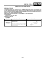
Oil type or grade
Engine oil
For CDN
0°
10°
30°
50°
70°
90°
110°
130°F
API service, SG type or higher, JASO standard
MA
YAMALUBE4 (20W40) or SAE 20W40
YAMALUBE4 (10W30) or SAE 10W30
YAMALUBE 4-CW (5W30) or SAE 5W30
-20°
-10°
0°
10°
20°
30°
40°
50°C
For Europe and Oceania
Final gear oil
Differential gear oil
SAE 80 API GL-4 Hypoid gear oil
SAE 80 API GL-4 Hypoid gear oil
–2–
GENERAL SPECIFICATIONS
Item
Transmission
Primary reduction system
Secondary reduction system
Secondary reduction ratio
Transmission type
Operation
Single speed automatic
Sub transmission ratio
SPEC
Standard
low
high
Reverse gear
Bulb voltage/wattage × quantity
Headlight
Tail/brake light
Indicator light
Neutral indicator light
Reverse indicator light
Coolant temperature warning light
Engine trouble warning light
EPS warning light
Park indicator light
On-command four-wheel drive/differential
gear lock indicator
High-range indicator light
Low-range indicator light
Differential gear lock indicator light
V-belt
Shaft drive
41/21 × 24/18 × 33/9 (9.544)
V-belt automatic
Left hand operation
2.380 ~ 0.700 : 1
31/16 (1.938)
31/27 (1.148)
23/14 × 28/23 (2.000)
12 V 35.0 W/35.0 W × 2
12 V 5.0/21.0 W × 1
LED
LED
LED
LED
LED (YFM7FGPX only)
LED
LCD
LED
LED
LED
–3–
ENGINE SPECIFICATIONS
SPEC
EBS01002
ENGINE SPECIFICATIONS
Item
Valve spring
Free length
Intake
Exhaust
Installed length (valve closed)
Intake
Exhaust
Compressed spring force (installed)
Intake
Exhaust
Standard
40.38 mm (1.59 in)
40.38 mm (1.59 in)
Limit
38.36 mm
(1.51 in)
38.36 mm
(1.51 in)
35.00 mm (1.38 in)
35.00 mm (1.38 in)
-------
171 ~ 197 N
(17.44 ~ 20.09 kgf, 38.44 ~ 44.29 lb)
171 ~ 197 N
(17.44 ~ 20.09 kgf, 38.44 ~ 44.29 lb)
-------
Spring tilt
Intake
----
Exhaust
----
Winding direction (top view)
Intake
Exhaust
2.5°/1.80 mm
(2.5°/0.071 in)
2.5°/1.80 mm
(2.5°/0.071 in)
Clockwise
Clockwise
–4–
-------
CHASSIS SPECIFICATIONS
SPEC
EBS01003
CHASSIS SPECIFICATIONS
Item
Front wheel
Type
Rim size
Rim material
Standard
Maximum radial wheel runout
Panel wheel
12 × 6.0 AT
Aluminum (YFM7FGPX)
Steel (YFM7FGX)
----
Maximum lateral wheel runout
----
Rear wheel
Type
Rim size
Rim material
Maximum radial wheel runout
Panel wheel
12 × 7.5 AT
Aluminum (YFM7FGPX)
Steel (YFM7FGX)
----
Maximum lateral wheel runout
----
–5–
Limit
---------2.0 mm
(0.08 in)
2.0 mm
(0.08 in)
---------2.0 mm
(0.08 in)
2.0 mm
(0.08 in)
ELECTRICAL SPECIFICATIONS
SPEC
EBS01004
ELECTRICAL SPECIFICATIONS
Item
ECU
Model/manufacturer
Ignition coil
Model/manufacturer
Minimum ignition spark gap
Primary coil resistance
Secondary coil resistance
Circuit breaker
Circuit breaker type
Fuses
Main fuse
Headlight fuse
Signaling system fuse
Ignition fuse
Auxiliary DC jack fuse
Fuel injection system fuse
Four-wheel-drive motor fuse
EPS fuse
Radiator fan motor fuse
Spare fuse
Standard
Limit
F8T83472/MITSUBISHI
----
2JN/YAMAHA
6.0 mm (0.24 in)
2.16 ~ 2.64 Ω at 20 °C (68 °F)
8.64 ~ 12.96 kΩ at 20 °C (68 °F)
-------------
Fuse
----
40.0 A
15.0 A
5.0 A
10.0 A
15.0 A
15.0 A
10.0 A
40.0 A (YFM7FGPX only)
15.0 A
40.0 A
15.0 A
10.0 A
5.0 A
----------------------------------------
–6–
TIGHTENING TORQUES
SPEC
EBS01005
TIGHTENING TORQUES
ENGINE TIGHTENING TORQUES
Item
Oil filter cartridge union bolt
Exhaust pipe
Middle drive pinion gear nut
Part name
Union bolt
Nut
Nut
Thread
Q’ty
size
M20
M8
M22
1
4
1
Tightening torque
Nm m · kg ft · lb
30
14
190
3.0
1.4
19.0
22
10
140
Remarks
LT
Stake.
EBS01006
CHASSIS TIGHTENING TORQUES
Part to be tightened
Thread size
Steering stem bracket and frame
Steering stem support and frame
(YFM7FGX only)
EPS control unit and frame (YFM7FGPX only)
Pitman arm nut (YFM7FGX)
Pitman arm nut (YFM7FGPX)
Steering stem joint bolt (YFM7FGPX only)
Steering stem bearing and frame
(YFM7FGPX only)
Steering stem bearing nut (YFM7FGPX only)
EPS motor cover (YFM7FGPX only)
–7–
Tightening torque
Nm m · kg ft · lb
Remarks
M10
51
5.1
37
LT
M8
30
3.0
22
LT
M8
M14
M16
M8
30
190
210
35
3.0
19.0
21.0
3.5
22
140
150
25
M10
51
5.1
37
M22
M6
125
7
12.5
0.7
90
5.1
LT
LT
LT
SPEC
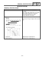
CABLE ROUTING
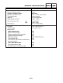
EBS00028
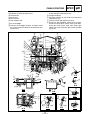
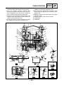
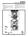
CABLE ROUTING
1 Coolant reservoir hose
2 Radiator fan motor breather hose
3 Differential gear case breather hose
4 EPS motor breather hose (YFM7FGPX only)
5 Ground lead
6 Coolant reservoir breather hose
7 Throttle cable
8 Fuel injector lead
9 Final gear case breather hose
0 Speed sensor lead
A Crankshaft position sensor lead
B Differential gear motor lead
C EPS torque sensor lead (YFM7FGPX only)
D Fast idle plunger outlet hose
E Horn switch lead (for Europe and Oceania)
F Radiator outlet hose
G Gear position switch lead
H Reverse switch lead
Ê
2
1
Ë
7
34 5 È 6 É
E
8Ì
A
Ó
B
D
C
A
B
Ò
D
C
9
Ñ
0
C
A
E
Ð
E
D
Ï B Î Í Û
F
5
Ô
1
Ü
F
1
4
A-A
Õ
G
Ö
B-B
9Ù
1
1
4
C-C
AØ
Õ
F
C-C
Õ
A
H
D
5
IÚ
E-E
–8–
B-B
Ü
Û
C
×
0Ø
J
Õ
F
SPEC
CABLE ROUTING
Ë Route the coolant reservoir breather hose to the
outside of the fast idle plunger outlet hose.
Ì Route the fuel injector lead under the fuel hose.
Í Fasten the radiator outlet hose to the frame with
the plastic band, making sure to face the end of
the band inward.
Î Route the EPS motor breather hose under the
coolant reservoir hose.
I Shift control cable
J Starter motor lead
È Face the end of the coolant reservoir breather
hose downward.
É Route the ground lead, radiator fan motor
breather hose, differential gear case breather
hose, and EPS motor breather hose to the inside
of the fast idle plunger outlet hose.
Ê Pass the radiator fan motor breather hose
through the larger diameter guide.
Ê
2
1
Ë
7
34 5 È 6 É
E
8Ì
A
Ó
B
D
C
A
B
Ò
D
C
9
Ñ
0
C
A
E
Ð
E
D
Ï B Î Í Û
F
5
Ô
1
Ü
F
1
4
A-A
Õ
G
Ö
B-B
9Ù
1
1
4
C-C
AØ
Õ
F
C-C
Õ
A
H
D
5
IÚ
E-E
–9–
B-B
Ü
Û
C
×
0Ø
J
Õ
F
SPEC
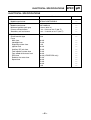
CABLE ROUTING
Ó Route the radiator fan motor breather hose, differential gear case breather hose, and horn
switch lead to the inside of the fast idle plunger
outlet hose and radiator outlet hose.
Ô Make sure that the catch of the holder is facing
outward.
Õ Face the end of the plastic band inward.
Ö Route the fuel tank drain hose and position the
end of the hose as shown in the illustration.
Ï Place the EPS torque sensor lead and differential gear motor lead in the holder, and then insert
the ends of the holder into the hole in the stay on
the frame.
Ð Route the differential gear case breather hose to
the inside of the frame.
Ñ Fasten the differential gear case breather hose
to the frame with the plastic band, making sure
to face the end of the band inward.
Ò Attach the ground lead terminal to the frame
using the bolt.
Ê
2
1
Ë
7
34 5 È 6 É
E
8Ì
A
Ó
B
D
C
A
B
Ò
D
C
9
Ñ
0
C
A
E
Ð
E
D
Ï B Î Í Û
F
5
Ô
1
Ü
F
1
4
A-A
Õ
G
Ö
B-B
9Ù
1
1
4
C-C
AØ
Õ
F
C-C
Õ
A
H
D
5
IÚ
E-E
– 10 –
B-B
Ü
Û
C
×
0Ø
J
Õ
F
SPEC
CABLE ROUTING
Û YFM7FGPX
Ü YFM7FGX
× Pass the speed sensor lead, AC magneto lead,
and final gear case breather hose through the
guide in the order listed.
Ø Route the speed sensor lead, AC magneto lead,
and final gear case breather hose to the right of
the reverse switch.
Ù Route the final gear case breather hose above
the reverse switch lead and ground leads.
Ú Route the shift control cable under the gear position switch lead, speed sensor lead, and crankshaft position sensor lead.
Ê
2
1
Ë
7
34 5 È 6 É
E
8Ì
A
Ó
B
D
C
A
B
Ò
D
C
9
Ñ
0
C
A
E
Ð
E
D
Ï B Î Í Û
F
5
Ô
1
Ü
F
1
4
A-A
Õ
G
Ö
B-B
9Ù
1
1
4
C-C
AØ
Õ
F
C-C
Õ
A
H
D
5
IÚ
E-E
– 11 –
B-B
Ü
Û
C
×
0Ø
J
Õ
F
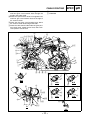
CABLE ROUTING
1 Wire harness
2 Fuel injector lead
3 Fuel hose
4 Intake air temperature sensor lead
5 Final gear case breather hose
6 Ground lead
7 Starter motor lead
8 Air filter case breather hose
9 Main switch lead
0 Auxiliary DC jack lead
A EPS motor lead (YFM7FGPX only)
SPEC
B Differential gear motor lead
C EPS torque sensor lead (YFM7FGPX only)
D Radiator fan motor lead
E Radiator inlet hose
F EPS motor breather hose (YFM7FGPX only)
G Spark plug lead
H Rear brake cable
I Shift control cable
J Fuel tank drain hose
K Gear position switch lead
L AC magneto lead
567 8 É
Ê
4
90A B C
3È
2
1
DË
B
Ï
C
B
A
N
Î
E
A
D
F
M
L
K
E
C
E
Ì
D
F
JÍ
Ð
5
2
I
A-A
P
O
Ò
B-B
C-C
I
B
C
Ó
B
Ñ
H
G
I
Ô
A
D-D
5 6
1
N
7
1
Ö
B
H G
7
6
L
Õ
F
D-D
Ó
E-E
– 12 –
F-F
CABLE ROUTING
SPEC
Ê Route the final gear case breather hose above
the V-belt cooling duct 1.
Ë Route the radiator fan motor lead between the
electrical components tray and the radiator inlet
hose.
Ì Fasten the radiator fan motor lead to the frame
with the plastic band, making sure to face the
end of the band inward.
M Speed sensor lead
N Coolant temperature sensor lead
O EPS motor lead coupler (YFM7FGPX only)
P EPS torque sensor lead coupler
(YFM7FGPX only)
È Route the fuel hose between the wire harness
and the fuel tank drain hose.
É Route the coolant temperature sensor lead
above the fast idle plunger inlet hose.
567 8 É
Ê
4
90A B C
3È
2
1
DË
B
Ï
C
B
A
N
Î
E
A
D
F
M
L
K
E
C
E
Ì
D
F
JÍ
Ð
5
2
I
A-A
P
O
Ò
B-B
C-C
I
B
C
Ó
B
Ñ
H
G
I
Ô
A
D-D
5 6
1
N
7
1
Ö
B
H G
7
6
L
Õ
F
D-D
Ó
E-E
– 13 –
F-F
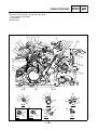
CABLE ROUTING
SPEC
Ï Route the fuel injector lead and coolant temperature sensor lead to the inside of the ground
lead, starter motor lead, final gear case breather
hose, and wire harness.
Ð Face the end of the plastic band inward.
Ñ Pass the plastic band through the hole in the
plastic cover, and then fasten the leads and
hose with the band, making sure to face the end
of the band downward.
Ò Insert the projection on the coupler into the hole
in the frame from the inside of the frame.
Í Route the fuel tank drain hose to the inside of
the leads and fuel hose, making sure to position
the end of the drain hose as shown in the illustration.
Î Fasten the final gear case breather hose,
ground lead, starter motor lead, fuel injector
lead, coolant temperature sensor lead, AC magneto lead, and wire harness with the plastic
band, making sure to position the band near the
split in the wire harness.
567 8 É
Ê
4
90A B C
3È
2
1
DË
B
Ï
C
B
A
N
Î
E
A
D
F
M
L
K
E
C
E
Ì
D
F
JÍ
Ð
5
2
I
A-A
P
O
Ò
B-B
C-C
I
B
C
Ó
B
Ñ
H
G
I
Ô
A
D-D
5 6
1
N
7
1
Ö
B
H G
7
6
L
Õ
F
D-D
Ó
E-E
– 14 –
F-F
CABLE ROUTING
SPEC
Ó Face the end of the plastic band inward.
Ô Fasten the spark plug lead with the larger diameter section of each holder.
Õ YFM7FGPX
Ö YFM7FGX
567 8 É
Ê
4
90A B C
3È
2
1
DË
B
Ï
C
B
A
N
Î
E
A
D
F
M
L
K
E
C
E
Ì
D
F
JÍ
Ð
5
2
I
A-A
P
O
Ò
B-B
C-C
I
B
C
Ó
B
Ñ
H
G
I
Ô
A
D-D
5 6
1
N
7
1
Ö
B
H G
7
6
L
Õ
F
D-D
Ó
E-E
– 15 –
F-F
SPEC
CABLE ROUTING
1 Left headlight lead
2 Negative battery lead
3 Right headlight lead
4 EPS (electric power steering) control unit
(YFM7FGPX only)
5 Radiator fan motor lead
6 EPS control unit lead (YFM7FGPX only)
7 Auxiliary DC jack lead
8 Main switch lead
9 Final gear case breather hose
0 Starter motor lead
A Differential gear motor lead
B Ignition coil lead
C Meter lead
D Lean angle sensor lead
E Coolant reservoir breather hose
F Main fuse
G EPS fuse (YFM7FGPX only)
H Positive battery lead
I Horn switch lead (for Europe and Oceania)
J Coolant reservoir hose
K EPS motor breather hose (YFM7FGPX only)
É
1
Ê
2
3
M
L
K
Ë
È
B
Ô
4
JÓ
Ò
É
C
5
C
A
A
6
I
Ì
H
Ñ
G
F
Ð
E
8
2
Í
E
ÏÎC 6
B D
D
A0
B
M L I
2
7
E
D
9
C-C
D
EÕ
KG
N
Ö
G
35
P
A-A
Ø
3
4
O5
F
6
F
E-E
– 16 –
Q
6
B-B
×
G-G
×
1
O
P
D-D
P
O
F-F
F
F
P
P
E-E
Ø
Q
F-F
SPEC
CABLE ROUTING
Ê Route the negative battery lead along the guide
on the electrical components tray.
Ë To right headlight
Ì Place the couplers on the inside of the electrical
components tray.
Í To main switch and auxiliary DC jack
Î Fasten the left handlebar switch lead, on-command four-wheel-drive motor switch and differential gear lock switch lead, front brake light
switch lead, and rear brake light switch lead with
the clamp.
L Differential gear case breather hose
M Radiator fan motor breather hose
N Ground lead
O Relay lead
P Wire harness
Q Joint coupler lead
È To left headlight
É Connect the headlight coupler, and then fasten
the coupler with the holder on the electrical components tray.
É
1
Ê
2
3
M
L
K
Ë
È
B
Ô
4
JÓ
Ò
É
C
5
C
A
A
6
I
Ì
H
Ñ
G
F
Ð
E
8
2
Í
E
ÏÎC 6
B D
D
A0
B
M L I
2
7
E
D
9
C-C
D
EÕ
KG
N
Ö
G
35
P
A-A
Ø
3
4
O5
F
6
F
E-E
– 17 –
Q
6
B-B
×
G-G
×
1
O
P
D-D
P
O
F-F
F
F
P
P
E-E
Ø
Q
F-F
SPEC
CABLE ROUTING
Ó Fasten the coolant reservoir hose with the
holder on the electrical components tray.
Ô Pass the hoses, ground lead, and horn switch
lead through the opening in the electrical components tray.
Õ Route the coolant reservoir breather hose above
the other hoses.
Ö Route the hoses to the inside of the bolt.
× YFM7FGPX
Ø YFM7FGX
Ï Fasten the joint coupler lead and horn switch
lead (for Europe and Oceania) with the clamp.
Ð Pass the coolant reservoir breather hose
through the guides on the plastic cover and electrical components tray and route it under the
positive battery lead and starter motor lead.
Ñ Route the hoses under the positive battery lead,
and then route them upward, to the inside of the
coolant reservoir breather hose.
Ò Fasten the coolant reservoir breather hose with
the holder on the electrical components tray.
É
1
Ê
2
3
M
L
K
Ë
È
B
Ô
4
JÓ
Ò
É
C
5
C
A
A
6
I
Ì
H
Ñ
G
F
Ð
E
8
2
Í
E
ÏÎC 6
B D
D
A0
B
M L I
2
7
E
D
9
C-C
D
EÕ
KG
N
Ö
G
35
P
A-A
Ø
3
4
O5
F
6
F
E-E
– 18 –
Q
6
B-B
×
G-G
×
1
O
P
D-D
P
O
F-F
F
F
P
P
E-E
Ø
Q
F-F
CABLE ROUTING
1 Throttle cable
2 Rear brake hose
3 Rear brake cable
4 Front brake hose
5 Negative battery lead
6 Final gear case breather hose
7 Starter motor lead
8 Throttle body breather hose
9 Engine idling speed adjusting cable
0 Intake air pressure sensor lead
SPEC
A Breather hose (air filter case to fast idle plunger
unit)
B TPS lead
C Intake air temperature sensor lead
D Fuel injector lead
E Coolant temperature sensor lead
F Rectifier/regulator lead
G AC magneto lead
H Fuel hose
I Tail/brake light lead
J Fuel pump lead
4
5
6È
7
8
9
0É
A
3
2
A
A
1
KÐ
Ê
Ë
Ï
B
B
B
C
DÌ
EÌ
F
G
J
H
Í
1Ñ
C
C
A-A
I
I
Ò
L C B
Î
B-B
C-C
– 19 –
CABLE ROUTING
Ì Route the fuel injector lead and coolant temperature sensor lead to the outside of the frame.
Í Pass the tail/brake light lead through the hole in
the rear fender.
Î Fasten the tail/brake light lead with the holder,
making sure that the coupler is positioned to the
rear of the holder.
Ï Route the throttle cable under the plastic cover.
Ð Route the fast idle plunger outlet hose above the
plastic cover.
K Fast idle plunger outlet hose
L Wire harness
È Route the final gear case breather hose on top
of the leads.
É Route the intake air pressure sensor lead to the
front of the breather hose (air filter case to fast
idle plunger unit) and above the engine idling
speed adjusting cable.
Ê To engine
Ë To air filter case
4
5
6È
7
8
9
0É
A
3
2
A
SPEC
A
1
KÐ
Ê
Ë
Ï
B
B
B
C
DÌ
EÌ
F
G
J
H
Í
1Ñ
C
C
A-A
I
I
Ò
L C B
Î
B-B
C-C
– 20 –
CABLE ROUTING
SPEC
Ñ Pass the throttle cable through the guide on the
plastic cover.
Ò Insert the projection on the wire harness holder
into the hole in the plastic cover.
4
5
6È
7
8
9
0É
A
3
2
A
A
1
KÐ
Ê
Ë
Ï
B
B
B
C
DÌ
EÌ
F
G
J
H
Í
1Ñ
C
C
A-A
I
I
Ò
L C B
Î
B-B
C-C
– 21 –
INTRODUCTION/PERIODIC MAINTENANCE CHART
FOR THE EMISSION CONTROL SYSTEM
CHK
ADJ
EBS00029
PERIODIC CHECKS AND ADJUSTMENTS
INTRODUCTION
This chapter includes all information necessary to perform recommended checks and adjustments.
These preventive maintenance procedures, if followed, will ensure more reliable vehicle operation
and a longer service life. The need for costly overhaul work will be greatly reduced. This information
applies to vehicles already in service as well as to new vehicles that are being prepared for sale. All
service technicians should be familiar with this entire chapter.
EBU21742
PERIODIC MAINTENANCE CHART FOR THE EMISSION CONTROL
SYSTEM
NOTE:
• For ATVs not equipped with an odometer or an hour meter, follow the month maintenance intervals.
• For ATVs equipped with an odometer or an hour meter, follow the km (mi) or hours maintenance
intervals. However, keep in mind that if the ATV isn’t used for a long period of time, the month
maintenance intervals should be followed.
• Items marked with an asterisk should be performed by a Yamaha dealer as they require special
tools, data and technical skills.
INITIAL
NO.
1
*
2
ITEM
CHECK OR MAINTENANCE JOB
Whichever
comes first
EVERY
month
1
3
6
6
12
km (mi)
320
(200)
1300
(800)
2500
(1600)
2500
(1600)
5000
(3200)
hours
20
80
160
160
320
√
√
√
√
√
√
√
√
√
Fuel line
• Check fuel hoses for cracks or other damage, and
replace if necessary.
Spark plug
• Check condition and clean, regap, or replace if necessary.
√
Valves
• Check valve clearance and adjust if necessary.
√
√
√
3
*
4
*
Fuel injection
• Check and adjust engine idle speed.
√
√
√
*
Crankcase
breather system
• Check breather hose for cracks or other damage,
and replace if necessary.
√
√
√
Exhaust system
• Check for leakage and replace gasket(s) if necessary.
• Check for looseness and tighten all screw clamps
and joints if necessary.
√
√
√
Spark arrester
• Clean.
√
√
√
5
6
7
*
– 22 –
√
GENERAL MAINTENANCE AND LUBRICATION CHART
CHK
ADJ
EBU21863
GENERAL MAINTENANCE AND LUBRICATION CHART
INITIAL
NO.
ITEM
CHECK OR MAINTENANCE JOB
Whichever
comes first
1
3
6
6
12
km (mi)
320
(200)
1300
(800)
2500
(1600)
2500
(1600)
5000
(3200)
20
80
160
160
320
hours
1
2
*
Air filter element
• Clean and replace if necessary.
Front brake
• Check operation and correct if necessary.
• Check fluid level and ATV for fluid leakage, and
correct if necessary.
Every 20–40 hours (more often in wet or dusty
areas)
√
• Replace brake pads.
3
*
Rear brake
*
Brake hoses
√
√
√
√
Whenever worn to the limit
• Check operation and correct if necessary.
• Check brake pedal free play and adjust if necessary.
• Check fluid level and ATV for fluid leakage, and
correct if necessary.
√
• Replace brake pads.
4
EVERY
month
√
√
√
√
Whenever worn to the limit
• Check for cracks or other damage, and replace if
necessary.
√
• Replace.
√
√
√
√
√
√
Every 4 years
5
*
Rear brake hose
protectors
• Check for wear, cracks or other damage, and
replace if necessary.
√
6
*
Wheels
• Check runout and for damage, and replace if necessary.
√
√
√
√
7
*
Tires
• Check tread depth and for damage, and replace if
necessary.
• Check air pressure and balance, and correct if necessary.
√
√
√
√
8
*
Wheel hub bearings
• Check for looseness or damage, and replace if
necessary.
√
√
√
√
9
*
V-belt
• Check for wear, cracks or other damage, and
replace if necessary.
√
√
√
√
10 *
Chassis fasteners
• Make sure that all nuts, bolts, and screws are properly tightened.
√
√
√
√
11 *
Shock absorber
assemblies
• Check operation and correct if necessary.
• Check for oil leakage and replace if necessary.
√
√
√
12 *
Stabilizer bushes
• Check for cracks or other damage, and replace if
necessary.
√
√
√
13 *
Rear knuckle pivots
• Lubricate with lithium-soap-based grease.
√
√
√
14 *
Steering shaft
• Lubricate with lithium-soap-based grease.
√
√
√
15 *
Steering system
• Check operation and repair or replace if damaged.
• Check toe-in and adjust if necessary.
√
√
√
16 *
Engine mount
• Check for cracks or other damage, and replace if
necessary.
√
√
√
17 *
Axle boots
• Check for cracks or other damage, and replace if
necessary.
√
√
√
√
18
Engine oil
• Change.
• Check ATV for oil leakage, and correct if necessary.
√
√
√
√
19
Engine oil filter
cartridge
• Replace.
√
√
20
• Change.
Differential gear oil • Check ATV for oil leakage, and correct if necessary.
– 23 –
√
√
√
√
√
√
√
√
GENERAL MAINTENANCE AND LUBRICATION CHART
CHK
ADJ
INITIAL
NO.
ITEM
CHECK OR MAINTENANCE JOB
Whichever
comes first
EVERY
month
1
3
6
6
12
km (mi)
320
(200)
1300
(800)
2500
(1600)
2500
(1600)
5000
(3200)
hours
20
80
160
160
320
• Change.
• Check ATV for oil leakage, and correct if necessary.
√
• Check coolant level and ATV for coolant leakage,
and correct if necessary.
√
21
Final gear oil
22
Cooling system
23 *
Moving parts and
cables
• Lubricate.
24 *
Drive select lever
safety system
cable
• Check operation and adjust or replace if necessary.
25 *
• Check operation and correct if necessary.
• Check throttle cable free play and adjust if necesThrottle lever
sary.
housing and cable
• Lubricate throttle lever housing and cable.
√
26 *
Front and rear
brake switches
• Check operation and correct if necessary.
27 *
Lights and
switches
• Check operation and correct if necessary.
• Adjust headlight beams.
√
√
√
√
√
√
√
√
√
√
√
√
√
√
√
√
√
√
√
√
√
√
√
√
• Replace coolant.
√
Every 2 years
√
EBU23070
NOTE:
• The air filter needs more frequent service if you are riding in unusually wet or dusty areas.
• Hydraulic brake service
• Regularly check and, if necessary, correct the brake fluid level.
• Every two years replace the internal components of the brake master cylinders and calipers, and
change the brake fluid.
• Replace the brake hoses every four years and if cracked or damaged.
– 24 –
AIR FILTER CASE
CHK
ADJ
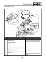
AIR FILTER CASE
2
3
1
8
New
9
New
4
5
6
7
Order
1
2
3
4
5
6
7
8
9
Job/Part
Removing the air filter case
Seat/side panels
Q’ty
Air filter case cover
Air filter element
Air filter element frame
Air filter case joint clamp screw
Intake air temperature sensor coupler
Breather hose (air filter case to fast idle
plunger unit)
Cylinder head breather hose
Intake air temperature sensor
Air filter case
1
1
1
1
1
1
1
1
1
Remarks
Remove the parts in the order listed.
Refer to “SEAT AND SIDE PANELS” in
chapter 3. (Manual No.: 3B4-28197-E0)
Loosen.
Disconnect.
Disconnect.
Disconnect.
For installation, reverse the removal procedure.
– 25 –
ADJUSTING THE FRONT SHOCK ABSORBERS/
ADJUSTING THE REAR SHOCK ABSORBERS
CHK
ADJ
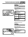
EBS00110
ADJUSTING THE FRONT SHOCK
ABSORBERS
WARNING
_
Always adjust the spring preload for both
front shock absorbers to the same setting.
Uneven adjustment can cause poor handling and loss of stability.
1 2
3
4
1. Adjust:
• spring preload
Turn the adjuster 1 in direction a or b.
5
Steering nut wrench
90890-01443
Spanner wrench
YU-33975
1
a
b
Direction a
Spring preload is
increased (suspension
is harder).
Direction b
Spring preload is
decreased (suspension
is softer).
Standard position: 3
Minimum position: 1
Maximum position: 5
EBS00112
ADJUSTING THE REAR SHOCK
ABSORBERS
WARNING
_
Always adjust the spring preload for both
rear shock absorbers to the same setting.
Uneven adjustment can cause poor handling and loss of stability.
1 2
3
4
1
5
1. Adjust:
• spring preload
Turn the adjuster 1 in direction a or b.
Steering nut wrench
90890-01443
Spanner wrench
YU-33975
b
a
– 26 –
ADJUSTING THE REAR SHOCK ABSORBERS
Direction a
Spring preload is
increased (suspension
is harder).
Direction b
Spring preload is
decreased (suspension
is softer).
Standard position: 3
Minimum position: 1
Maximum position: 5
– 27 –
CHK
ADJ
ENG
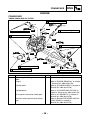
CRANKCASE
EBS00319
ENGINE
CRANKCASE
TIMING CHAIN AND OIL FILTER
T.
17 Nm (1.7 m • kg, 12 ft • Ib)
R.
9
E
6
8 New
LS
T.
New
R.
T.
7 Nm (0.7 m • kg, 5.1 ft • Ib)
10 Nm (1.0 m • kg, 7.2 ft • Ib)
R.
LS
T.
R.
30 Nm (3.0 m • kg, 22 ft • Ib)
New
LS
5
T.
R.
New
10 Nm (1.0 m • kg, 7.2 ft • Ib)
1
LS
LT
LT
New
4
LT
LS
LT
LT
3
New
2
New
7
LT
T.
R.
New
30 Nm (3.0 m • kg, 22 ft • Ib)
LT
T.
R.
17 Nm (1.7 m • kg, 12 ft • Ib)
T.
R.
Order
Job/Part
Removing the timing chain and oil
filter
Engine
Q’ty
Cylinder head
Cylinder/piston
AC magneto rotor/starter wheel gear
Balancer driven gear/oil pump driven
gear
– 28 –
10 Nm (1.0 m • kg, 7.2 ft • Ib)
Remarks
Remove the parts in the order listed.
Refer to “ENGINE REMOVAL” in chapter
4. (Manual No.: 3B4-28197-E0)
Refer to “CYLINDER HEAD” in chapter 4.
(Manual No.: 3B4-28197-E0)
Refer to “CYLINDER AND PISTON” in
chapter 4. (Manual No.: 3B4-28197-E0)
Refer to “AC MAGNETO” in chapter 4.
(Manual No.: 3B4-28197-E0)
Refer to “BALANCER GEARS AND OIL
PUMP GEARS” in chapter 4.
(Manual No.: 3B4-28197-E0)
ENG
CRANKCASE
T.
17 Nm (1.7 m • kg, 12 ft • Ib)
R.
9
E
6
8 New
LS
T.
New
R.
T.
7 Nm (0.7 m • kg, 5.1 ft • Ib)
10 Nm (1.0 m • kg, 7.2 ft • Ib)
R.
LS
T.
R.
30 Nm (3.0 m • kg, 22 ft • Ib)
New
LS
5
T.
R.
New
10 Nm (1.0 m • kg, 7.2 ft • Ib)
1
LS
LT
LT
New
4
LT
LS
LT
LT
3
New
2
New
7
LT
T.
R.
New
30 Nm (3.0 m • kg, 22 ft • Ib)
LT
T.
R.
17 Nm (1.7 m • kg, 12 ft • Ib)
T.
R.
Order
Job/Part
Primary sheave assembly/secondary
sheave assembly
Q’ty
Clutch carrier assembly
1
2
3
4
5
6
7
8
9
Timing chain guide (intake side)
Timing chain guide
Timing chain
Oil filter cartridge
Speed sensor
Dipstick
Relief valve assembly
Reverse switch
Gear position switch
10 Nm (1.0 m • kg, 7.2 ft • Ib)
Remarks
Refer to “PRIMARY AND SECONDARY
SHEAVES” in chapter 4.
(Manual No.: 3B4-28197-E0)
Refer to “CLUTCH” in chapter 4.
(Manual No.: 3B4-28197-E0)
1
1
1
1
1
1
1
1
1
For installation, reverse the removal procedure.
– 29 –
FI
THROTTLE BODY
EAS00909
FUEL INJECTION SYSTEM
THROTTLE BODY
LS
4
8
New
10
7
1
3
2
12
11
13
6
9
T.
R.
Order
5
9
3 Nm (0.3 m • kg, 2.2 ft • Ib)
Job/Part
Removing the throttle body
Air filter case
Q’ty
Coolant
1
2
3
4
5
6
7
8
Intake air pressure sensor coupler
Throttle position sensor coupler
Throttle body breather hose
Breather hose (air filter case to fast idle
plunger unit)
Fast idle plunger outlet hose
Fast idle plunger inlet hose
Throttle cable housing cover
Throttle cable
1
1
1
1
1
1
1
1
– 30 –
Remarks
Remove the parts in the order listed.
Refer to “AIR FILTER CASE” in chapter
3. (Manual No.: 3B4-28197-E0)
Drain.
Refer to “CHANGING THE COOLANT” in
chapter 3. (Manual No.: 3B4-28197-E0)
Disconnect.
Disconnect.
Disconnect.
Disconnect.
Disconnect.
FI
THROTTLE BODY
LS
4
8
New
10
7
1
3
2
12
11
13
9
T.
R.
Order
9
10
Job/Part
Throttle body joint clamp screw
Throttle body assembly
5
6
9
3 Nm (0.3 m • kg, 2.2 ft • Ib)
Q’ty
2
Loosen.
1
11
Fuel hose
1
12
13
Fuel injector coupler
Throttle body joint
1
1
– 31 –
Remarks
Refer to “INSTALLING THE
THROTTLE BODY ASSEMBLY” in chapter 6.
(Manual No.: 3B4-28197-E0)
Disconnect.
Refer to “REMOVING THE THROTTLE
BODY ASSEMBLY” and “INSTALLING
THE THROTTLE BODY ASSEMBLY” in
chapter 6. (Manual No.: 3B4-28197-E0)
Disconnect.
Refer to “INSTALLING THE THROTTLE
BODY ASSEMBLY” in chapter 6.
(Manual No.: 3B4-28197-E0)
For installation, reverse the removal procedure.
FI
THROTTLE BODY
6
4
New
3
5
New
New
7
1
2
Order
1
2
3
4
5
6
7
Job/Part
Disassembling the throttle body
assembly
Intake air pressure sensor
Intake air pressure sensor hose
Throttle position sensor
Injector fuel rail
Fuel injector
Fast idle plunger unit
Throttle body
Q’ty
1
1
1
1
1
1
1
Remarks
Remove the parts in the order listed.
CAUTION:
The throttle body should not be disassembled.
For assembly, reverse the disassembly
procedure.
– 32 –
STEERING SYSTEM
CHAS
EBS00454
CHASSIS
STEERING SYSTEM
STEERING STEM (YFM7FGX only)
T.
10
R.
51 Nm (5.1 m • kg, 37 ft • Ib)
T.
LS
R.
5 New
23 Nm (2.3 m • kg, 17 ft • Ib)
LS
New 1
2
4
3
16
3
LT
LT
5 New
LS
LS
New 12
T.
30 Nm (3.0 m • kg, 22 ft • Ib)
R.
New 14
LS
15
New
(4)
6
11
LT
6
LS
Job/Part
Removing the steering stem
Front fender
R.
Order
T.
8
Electrical components tray
1
2
3
4
5
Lock washer
Cable guide
Steering stem bushing
Collar
Oil seal
1
1
2
2
2
– 33 –
25 Nm (2.5 m • kg, 18 ft • Ib)
190 Nm (19.0 m • kg, 140 ft • lb)
Q’ty
Air filter case
Handlebar
R.
9
T.
New 13
7
Remarks
Remove the parts in the order listed.
Refer to “ENGINE SKID PLATES, SEAT,
CARRIERS AND FENDERS” in chapter
3. (Manual No.: 3B4-28197-E0)
Refer to “AIR FILTER CASE”.
Refer to “HANDLEBAR” in chapter 8.
(Manual No.: 3B4-28197-E0)
Refer to “ELECTRICAL COMPONENTS
TRAY” in chapter 3.
(Manual No.: 3B4-28197-E0)
Refer to “INSTALLING THE LOCK
WASHER (YFM7FGX only)”.
STEERING SYSTEM
T.
10
R.
51 Nm (5.1 m • kg, 37 ft • Ib)
T.
LS
R.
5 New
23 Nm (2.3 m • kg, 17 ft • Ib)
CHAS
LS
New 1
2
4
3
16
3
LT
LT
5 New
LS
LS
New 12
T.
30 Nm (3.0 m • kg, 22 ft • Ib)
R.
New 14
LS
15
New
(4)
6
11
LT
6
LS
Job/Part
Tie rod end nut
Tie rod
Pitman arm nut
Pitman arm
Steering stem
Steering stem support
Oil seal
Oil seal
Circlip
Bearing
Steering stem bracket
R.
Order
6
7
8
9
10
11
12
13
14
15
16
T.
8
R.
9
T.
New 13
7
25 Nm (2.5 m • kg, 18 ft • Ib)
190 Nm (19.0 m • kg, 140 ft • lb)
Q’ty
Remarks
2
2
Disconnect.
1
Refer to “INSTALLING THE PITMAN
ARM (YFM7FGX only)”.
1
1
1
1
1
1
1
1
For installation, reverse the removal procedure.
– 34 –
STEERING SYSTEM
CHAS
INSTALLING THE PITMAN ARM (YFM7FGX
only)
1. Install:
• pitman arm 1
• washer
• pitman arm nut
b
a
1
T.
190 Nm (19.0 m · kg, 140 ft · lb)
R.
• clip
NOTE:
Align the groove a in the pitman arm with the
steering stem spline b that is indented.
INSTALLING THE LOCK WASHER
(YFM7FGX only)
1. Install:
• cable guide
• lock washer New
• steering stem bushing bolts
a
T.
R.
a
23 Nm (2.3 m · kg, 17 ft · lb)
NOTE:
• Bend the lock washer tab a along a flat side
of the bolt.
• Pass the cable and hoses through the cable
guide. Refer to “CABLE ROUTING”.
– 35 –
STEERING SYSTEM
3
A
0
8
9
7 B G
INSTALLING THE STEERING STEM
(YFM7FGPX only)
1. Install:
• EPS unit 1
• washers
• EPS unit bolts 2
7
H
C
9
H
T.
UP
R.
5
6
D
E
4
2
F
2.
•
•
•
•
EPS unit bolt
30 Nm (3.0 m · kg, 22 ft · lb)
LOCTITE®
Install:
steering stem 3
steering stem bearing 4
collar 5
bearing nut 6
T.
(4)
R.
1
CHAS
125 Nm (12.5 m · kg, 90 ft · lb)
NOTE:
Install the steering stem bearing with the “UP”
mark facing up.
3.
•
•
•
•
•
•
•
Install:
oil seals 7 New
collars 8
steering stem bushings 9
cable guide 0
lock washer A New
steering stem bracket B
steering stem bolts C
(temporarily tighten)
NOTE:
Apply lithium-soap-based grease to the oil
seals and steering stem bushings.
– 36 –
ELEC
ELECTRICAL COMPONENTS
–
+
EBS00500
ELECTRICAL
ELECTRICAL COMPONENTS
1 Four-wheel-drive motor relay 3
2 Rear brake relay
3 Four-wheel-drive motor relay 2
4 Four-wheel-drive motor relay 1
5 Headlight relay
6 Fuel injection system fuse
7 Starter relay
1
2
8 EPS fuse (YFM7FGPX only)
9 Main fuse
0 Fuse box (ignition, headlights, four-wheel-drive
motor, radiator fan motor, signaling system, auxiliary DC jack)
A Radiator fan motor circuit breaker
B Rectifier/regulator
3
4
5
6
7
0
8
K
9
J
A
H
B
I
C
F
D
G
E
– 37 –
ELEC
ELECTRICAL COMPONENTS
–
+
C Reverse switch
D Gear position switch
E Auxiliary DC jack
F Main switch
G Differential gear motor
H EPS motor (YFM7FGPX only)
I EPS torque sensor (YFM7FGPX only)
J Horn (for Europe and Oceania)
K Radiator fan motor
1
2
3
4
5
6
7
0
8
K
9
J
A
H
B
I
C
F
D
G
E
– 38 –
ELECTRICAL COMPONENTS
1 Lean angle sensor
2 Radiator fan motor relay
3 Fuel injection system relay
4 Starting circuit cut-off relay
5 Front brake light switch
6 Rear brake light switch
7 Intake air temperature sensor
8 Intake air pressure sensor
9 TPS (throttle position sensor)
0 Fuel pump
A Speed sensor
1
ELEC
–
+
B Crankshaft position sensor
C Coolant temperature sensor
D Ignition coil
E Battery
F ECU (engine control unit)
G EPS (electric power steering) control unit
(YFM7FGPX only)
2
3
4
5
6
8
7
G
9
F
E
0
D
A
C
B
– 39 –
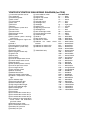
YFM7FGPX/YFM7FGX 2008 WIRING DIAGRAM (for CDN)
1 Crankshaft position sensor
2 AC magneto
3 Rectifier/regulator
4 Main switch
5 Frame ground
6 Main fuse
7 EPS fuse
8 Battery
9 Fuel injection system fuse
0 Starter relay
A Starter motor
B EPS torque sensor
C EPS motor
D EPS (electric power steering)
control unit
E EPS self-diagnosis signal connectors
F Diode 1
G Starting circuit cut-off relay
H Fuel injection system relay
I Diode 2
J Reverse switch
K ECU (engine control unit)
L Ignition coil
M Spark plug
N Fuel injector
O Intake air temperature sensor
P Coolant temperature sensor
Q Speed sensor
R TPS (throttle position sensor)
S Intake air pressure sensor
T Lean angle sensor
U Gear position switch
V Meter assembly
W Multifunction meter
X Engine trouble warning light
Y Coolant temperature warning
light
Z Park indicator light
[ Reverse indicator light
\ Neutral indicator light
] High-range indicator light
_ Low-range indicator light
a EPS warning light
b Fuel sender
c Fuel pump
d Four-wheel-drive motor relay 1
e Four-wheel-drive motor relay 2
f Four-wheel-drive motor relay 3
g On-command four-wheel-drive
motor switch and differential
gear lock switch
h Differential gear motor
i Four-wheel-drive motor fuse
j Auxiliary DC jack fuse
k Auxiliary DC jack
l Left handlebar switch
m Light switch
n Engine stop switch
o Start switch
p Override switch
q Headlight relay
r Headlight
s Ignition fuse
t Signaling system fuse
u Headlight fuse
v Rear brake light switch
w Front brake light switch
x Tail/brake light
y Diode 3
z Rear brake relay
{ Radiator fan motor
| Radiator fan motor circuit
breaker
} Radiator fan motor relay
~ Radiator fan motor fuse
È YFM7FGPX only
COLOR CODE
B............ Black
Br .......... Brown
G ........... Green
Gy ......... Gray
L ............ Blue
Lg .......... Light green
O ........... Orange
P............ Pink
R ........... Red
Sb.......... Sky blue
W........... White
Y............ Yellow
B/L......... Black/Blue
B/R ........ Black/Red
B/W ....... Black/White
B/Y ........ Black/Yellow
Br/B ....... Brown/Black
Br/L ....... Brown/Blue
Br/R ....... Brown/Red
Br/W ...... Brown/White
Br/Y ....... Brown/Yellow
G/R........ Green/Red
G/W ....... Green/White
G/Y ........ Green/Yellow
Gy/G...... Gray/Green
L/B......... Blue/Black
L/G ........ Blue/Green
L/R ........ Blue/Red
L/W........ Blue/White
L/Y......... Blue/Yellow
O/G ....... Orange/Green
O/W ....... Orange/White
R/B ........ Red/Black
R/L ........ Red/Blue
R/W ....... Red/White
R/Y ........ Red/Yellow
W/B ....... White/Black
W/L........ White/Blue
W/R ....... White/Red
Y/B ........ Yellow/Black
Y/G ........ Yellow/Green
Y/L......... Yellow/Blue
Y/R ........ Yellow/Red
Y/W ....... Yellow/White
YFM7FGPX/YFM7FGX 2008 WIRING DIAGRAM (for Europe and Oceania)
1 Crankshaft position sensor
2 AC magneto
3 Rectifier/regulator
4 Main switch
5 Frame ground
6 Main fuse
7 EPS fuse
8 Battery
9 Fuel injection system fuse
0 Starter relay
A Starter motor
B EPS torque sensor
C EPS motor
D EPS (electric power steering)
control unit
E EPS self-diagnosis signal connectors
F Diode 1
G Starting circuit cut-off relay
H Fuel injection system relay
I Diode 2
J Reverse switch
K ECU (engine control unit)
L Ignition coil
M Spark plug
N Fuel injector
O Intake air temperature sensor
P Coolant temperature sensor
Q Speed sensor
R TPS (throttle position sensor)
S Intake air pressure sensor
T Lean angle sensor
U Gear position switch
V Meter assembly
W Multifunction meter
X Engine trouble warning light
Y Coolant temperature warning
light
Z Park indicator light
[ Reverse indicator light
\ Neutral indicator light
] High-range indicator light
_ Low-range indicator light
a EPS warning light
b Fuel sender
c Fuel pump
d Four-wheel-drive motor relay 1
e Four-wheel-drive motor relay 2
f Four-wheel-drive motor relay 3
g On-command four-wheel-drive
motor switch and differential
gear lock switch
h Differential gear motor
i Four-wheel-drive motor fuse
j Auxiliary DC jack fuse
k Auxiliary DC jack
l Left handlebar switch
m Light switch
n Engine stop switch
o Start switch
p Override switch
q Headlight relay
r Headlight
s Ignition fuse
t Signaling system fuse
u Headlight fuse
v Rear brake light switch
w Front brake light switch
x Tail/brake light
y Diode 3
z Rear brake relay
{ Radiator fan motor
| Radiator fan motor circuit
breaker
} Radiator fan motor relay
~ Radiator fan motor fuse
å Horn switch
ç Horn
È YFM7FGPX only
COLOR CODE
B............ Black
Br .......... Brown
G ........... Green
Gy ......... Gray
L ............ Blue
Lg .......... Light green
O ........... Orange
P............ Pink
R ........... Red
Sb.......... Sky blue
W........... White
Y............ Yellow
B/L......... Black/Blue
B/R ........ Black/Red
B/W ....... Black/White
B/Y ........ Black/Yellow
Br/B ....... Brown/Black
Br/L ....... Brown/Blue
Br/R ....... Brown/Red
Br/W ...... Brown/White
Br/Y ....... Brown/Yellow
G/R........ Green/Red
G/W ....... Green/White
G/Y ........ Green/Yellow
Gy/G...... Gray/Green
L/B......... Blue/Black
L/G ........ Blue/Green
L/R ........ Blue/Red
L/W........ Blue/White
L/Y......... Blue/Yellow
O/G ....... Orange/Green
O/W ....... Orange/White
R/B ........ Red/Black
R/L ........ Red/Blue
R/W ....... Red/White
R/Y ........ Red/Yellow
W/B ....... White/Black
W/L........ White/Blue
W/R ....... White/Red
Y/B ........ Yellow/Black
Y/G ........ Yellow/Green
Y/L......... Yellow/Blue
Y/R ........ Yellow/Red
Y/W ....... Yellow/White
YAMAHA MOTOR CO., LTD.
2500 SHINGAI IWATA SHIZUOKA JAPAN
YFM7FGPX/YFM7FGX 2008
WIRING DIAGRAM (for CDN)
YFM7FGPX/YFM7FGX 2008
SCHÉMA DE CÂBLAGE (Canada)
È
B
B/L Gy
5
B/L
Gy
1
G/Y B
B
3
R
(GRAY)
R
R
G
W
B
B
W R G B R
B
W R G B R
B
R
R
R
B/W L/B B
R/B
W
G/R
O/W
L/B
L
B
L/B Br O
O/W Br L/B
G W G/R
G/R W
(BLACK)
(BLACK)
O
L
O
E
R/L R/B
G/W
Y/W
R/B
L
(BLACK)
J
(GRAY)
R/B
(BLACK)
R
Br
L/W
Br/B
R
L/W
Br/B
4
ON
8
R Br/L
OFF
9
B
B
Br/L R
(BLACK)
O
B/L
Br/W
Y/W
K
(GREEN)
G/Y
Sb B/Y
L/R
L/B
G/Y B/L
B/Y
I
B/Y
Br
Br/W
Sb L/B
L/R
H
A
B
B B
B/Y
G
F
L/W
B
B
B
L/W
B
R/L
R/B R/B
Br/B
Br
Br
0
(GRAY)
Br/L
L/W
(BLACK)
B
R/B R/B
L/W
R/L
Br/B
L/B
L/W Br
N
Br/W B/L
~
R/W
M
È
L/B
L
B
R
W Sb Gy Br Y/B Y/L Y/W B/L R/B O
B
D
R
P Y/G G/Y Br/W L
Y/W L/W W/B B/R Gy/G W/R G/W Lg G/R R/L L/R Y/R O/W
Gy
O/W
G/W
(GRAY)
R/B
Y
R
R
R/B
B
Br
È
7
6
W
(GRAY)
R/B
R
B
G
R
W W W
R
R/B
R
(BLACK)
W
W
W
W
W
W
2
C
B
G
P
L/B
R/L
Sb
L/R
R/L
B
B/L
Y
L
Y
Lg
Y/R
Y/B
G/R
W/B
B/R
Gy/G
W/R
Y/L
R/L
R/W
Br
G/Y
|
Y/R
Br/L
Br/L
c
R/B Y/R
j
s
R/B
R/L B B/W G/Y
(GRAY)
i
B
Br/L
L
P
B/L
P
L/B
Y/G
L
B/L
Y
L
S
B/L
P
L
Y/G
B/L
B/W
T
B/Y
B/W
Br/R
Br/Y
Q
(BLACK)
Br/R
P
Br/L
R
L
P
B/L
(BLACK)
Br
t
}
b
W L/Y
L
W
B/L
L
W
B/L
R/W Br
R/B
L W
B/L
B/L
G/Y
Y/G B/L
(GRAY)
B
Br/R B L/R
u
k
Br/L
L
Br/B
R/Y
Br/R
Br/R
Br/R
e
Br/R B L/G
G W/B
Br
B
L
Br/Y
B
L
L
B
P
B
(BLACK)
Gy
Br/R
w
v
Y
Y/W
R/Y
Br
m
R/B
L/B
B/Y
Y/B
L/B Sb
n
L/G B
V
L/R B
o
p
Br/R
Y/B
Br
Gy
OFF
PUSH
Y
L
R/B R/W
(GRAY)
L/R
L/G
L Y R/Y
B Lg L/B
Br R/B
L/G L/R
L/R L/G
(GRAY)
L/Y Sb
Sb L/B
(BLACK)
Y
G
(BLACK)
Y
L
L/R G/R
q
Gy
L
B
Y/L
B/W
X
G/Y G/R Br/B
B
Y
G/R
L/R
B
(GRAY)
g
Y
2WD
4WD
LOCK
(BLACK)
G/R Gy
B
Y/L Br B/W
Z
Br
[
(LIGHT GRAY)
Y L
L/Y
(BLACK)
B
Y/WB/Y
Y/W B/Y
B
z
B
Sb Gy
B
G
x
\
]
Y G
Y G
r
B B
Sb B/Y W/B
L/Y Br Br/B B/R
r
B
Br L/Y W/B B/R B Sb Br/B B/Y
Y G
B
G
G
Y
B
Y
B
B
Y G
B
(GRAY)
_
a
h
È
G/R
B
B
L/B W/R
Gy/G
W/R Gy/G
L
P
Gy W
G/Y
Br
Br/B
L/B Lg B
R/Y Y
y
Y
U
W
Y/W
L Y
Sb
Lg
OFF
Y/W
Y
d
Br/B
f
l
(BLACK)
(BLACK)
Br/Y
{
B
Br/R
Br/R
YFM7FGPX/YFM7FGX 2008
WIRING DIAGRAM
(for Europe and Oceania)
YFM7FGPX/YFM7FGX 2008
SCHÉMA DE CÂBLAGE
(Europe et Océanie)
È
B
B/L Gy
5
B/L
Gy
1
G/Y B
B
3
R
(GRAY)
R
R
G
W
B
W R G B R
B
W R G B R
B
(GRAY)
R/W
R
R
R
R
W Sb Gy Br Y/B Y/L Y/W B/L R/B O
R/B
W
G/R
O/W
L/B
L
B
O/W Br L/B
G W G/R
G/R W
(BLACK)
O
E
R/B
L
(BLACK)
J
(GRAY)
R/B
Br
L/W
8
R Br/L
OFF
B
B
Br/L R
(BLACK)
G
F
B
R/B Y/R
B
K
(GREEN)
G/Y
Sb B/Y
L/R
L/B
Y/W
Y/W
B/L
P
L/B
R/L
B
B/L
Y
L
Y
}
R/L
L
s
Br/L
L
Br/L
j
Br
Lg
Y/R
Y/B
G/R
W/B
B/R
Gy/G
W/R
Y/L
G/Y
c
b
R/L B B/W G/Y
(GRAY)
i
B
L
L
B
{
Br/L
P
L
P
B/L
P
L/B
Y/G
L
Br/L
Br/R
Br/R
Br/R
B
P
B
l
B P
Br/Y
Br/Y
R/Y
Br
m
R/B
L/B
w
n
o
p
Y
Y/W
L Y
L
R/B R/W
L/B Lg B
(GRAY)
B Lg L/B
Y
L/B Sb
L/G B
Y
Br/R
Y/B
Br
Gy
L
q
Y
G
L/R
L/G
Br R/B
L/G L/R
L/R L/G
(GRAY)
L/Y Sb
Sb L/B
(BLACK)
(BLACK)
L/R G/R
G/R Gy
Gy
L
B
G/R
L/R
B
(GRAY)
B
2WD
4WD
LOCK
Y/L
B/W
Y/L Br B/W
(BLACK)
Z
Br
[
(LIGHT GRAY)
Sb Gy
B
G
\
]
Y G
Y G
r
x
Sb B/Y W/B
L/Y Br Br/B B/R
r
Br L/Y W/B B/R B Sb Br/B B/Y
Y G
B
G
G
Y
B
Y
B
Y G
B
(GRAY)
B
_
a
h
È
G/R
B B
B
B
L/B W/R
Gy/G
W/R Gy/G
L
P
Gy W
Y
L/Y
Y/WB/Y
B
U
X
g
Y L
z
Sb
W
Y
Y
B
B
V
L/R B
(BLACK)
B
Y/G B/L
(GRAY)
(BLACK)
G/Y G/R Br/B
L Y R/Y
(BLACK)
Y/W B/Y
L
B
G/Y
Br
Br/B
B
Y/W
y
P
B/Y
v
R/Y Y
Y/W
Br/B
OFF
PUSH
B
Y
B/L
d
Lg
OFF
B B
B
S
Y/B
f
B Br/Y
ç
(BLACK)
Gy
Br/R
Br/R
Br/R
e
Br/R B L/G
Br/Y
å
(BLACK) B
B/W
Br/R
Br/B
Br
B
L
Br/R B L/R
R/Y
G W/B
(BLACK) P
Y
Y/G
B/L
T
k
Br B
B/L
B/W
B/Y
P
Q
(BLACK)
Br/R
u
B
R
L
Br/Y
B/L
(BLACK)
t
B
W L/Y
L
W
B/L
Sb
L/R
R/L
Br/L
L W
B/L
B/L
G/Y
L
W
B/L
R/B
B B
O
Br/W
G/Y B/L
B/Y
I
B/Y
Br
Br/W
Sb L/B
L/R
H
A
B
B
L/W
L/W
B
R/L
R/B R/B
Br/B
B/Y
Br
Br
0
(GRAY)
Br/L
R/B R/B
L/W
L/W
R/L
Br/B
L/B
L/W Br
(BLACK)
B
R/W
|
L/W
Br/B
N
Br/W B/L
Br/B
9
M
R/L R/B
G/W
(BLACK)
ON
R/W Br
L
O
È
L/B
L
L/B Br O
(BLACK)
R
Y/R
B
P Y/G G/Y Br/W L
R
4
Br
R
Y
L/W W/B B/R Gy/G W/R G/W Lg G/R R/L L/R Y/R O/W Y/W B/W L/B B
B
~
R/B
R
D
R
R/B
B
Gy
O/W
G/W
R/B
B
Br
È
7
6
W
(GRAY)
R/B
R
B
G
R
W W W
R
R/B
R
(BLACK)
W
W
W
W
W
W
2
C
B
G