1
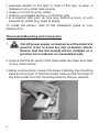
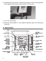
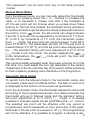
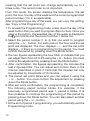
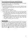
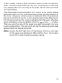
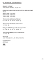
User’s Guide
DH E RS D/BW
Smart Programmable Digital Thermostat
for Heated Floors
For further information or to consult this guide online,
please visit www.schluter.com
08/2014
WARNING
WARNING
Before installing and operating this product, the owner
and/or installer must read, understand and follow
these instructions and keep them handy for future
reference. If these instructions are not followed, the
warranty will be considered null and void and the
manufacturer deems no further responsibility for this
product. Moreover, the following instructions must
be adhered to in order to avoid personal injuries or
property damages, serious injuries and potentially
fatal electric shocks. All electric connections must
be made by a qualified electrician, according to the
electrical and building codes effective in your region.
Do NOT connect this product to a supply source other
than 120 VAC, 208 VAC or 240 VAC, and do not exceed
the specified load limits. Protect the heating system
with the appropriate circuit breaker or fuse. You
must regularly clean dirt accumulations on or in the
thermostat. Do NOT use fluid to clean thermostat air
vents. Do NOT use where exposed to water.
1.Description
The DH E RS D/BW digital thermostat can be used to control
heating floors with electrical current − with a resistive load −
ranging from 0 A to 16 A at 120/208/240 VAC. It has an easy
user interface and can manage up to four programming periods
mode) and a
a day. It keeps the temperature of a room (
mode) at a requested set point with a high degree
floor (
of accuracy.
(factory setting): this control method is ideal
Floor Mode
in areas where you want a warm floor at any time and when
the temperature of the ambient air can be high without causing
discomfort. For example, in a bathroom.
2
Ambient Mode
(you only have to press down the
A/F button to switch from one mode to the other): this
control method is ideal when you want a stable ambient air
temperature (without fluctuation). Usually, this mode is used in
large and often occupied rooms where temperature variations
can be uncomfortable. For example, in a kitchen, a living room
or a bedroom.
Some factors cause variations in ambient air temperature. They
include large windows (heat losses or gains due to outside
temperature) and other heat sources such as a central heating
mode will
system, a fireplace, etc. In all these cases, the
ensure a uniform temperature.
This Thermostat is not Compatible with the Following
Installations:
•electrical current higher than 16 A with a resistive load (3840 W
@ 240 VAC, 3330 W @ 208 VAC and 1920 W @ 120 VAC);
•inductive load (presence of a contactor or relay); and
•central heating system.
Parts Supplied:
•one (1) thermostat;
•two (2) mounting screws;
•four (4) solderless connectors suitable for copper wires;
•one (1) floor temperature sensor.
2.Installation
Selection of Thermostat and Sensor Location
The thermostat must be mounted on a connection box, at
around 1.5 m (5 feet) above the floor level, on a section of the
wall exempt from pipes or air ducts.
Do not install the thermostat in a location where temperature
measurements could be altered. For example:
• close to a window, on an external wall, or close to a door
leading outside;
3
• exposed directly to the light or heat of the Sun, a lamp, a
fireplace or any other heat source;
•close or in front of an air outlet;
• close to concealed ducts or a chimney; and
• in a location with poor air flow (e.g. behind a door), or with
frequent air drafts (e.g. head of stairs).
To install the sensor, refer to the installation guide of your
heating floor.
Thermostat Mounting and Connection
1.Cut off power supply on lead wires at the electrical
panel in order to avoid any risk of electric shock;
Ensure that the thermostat will be installed on a
junction box located in an uninsulated wall;
2. Ensure that the air vents of the thermostat are clean and clear
of any obstructions;
3.Using a screwdriver, loosen the screw retaining the mounting
base and front part of the thermostat. Remove the front part of
the thermostat from the mounting base by tilting it upward;
4
4. Align and secure the mounting
base to the connection box using
the two screws supplied;
5. Route wires coming from the wall through the hole of the
mounting base and make the required connections using the
“Four-wire installation” figure, and using the supplied solderless
connectors. A pair of wires (black) must be connected to the
power source (120-208-240 VAC) and another pair (yellow)
must be connected to the heating cable (refer to the drawings
displayed on the back of the thermostat). For connections with
aluminum wires, you must use CO/ALR connectors. Please
note that thermostat wires do not have polarity, meaning that
any wire can be connected to the other. Then, connect the
wires of the floor temperature sensor at the indicated location
behind the thermostat. Two floor temperature sensors are
provided - one with the DITRA-HEAT-E-RS thermostat and
one with the DITRA-HEAT-E-HK heating cables. Both floor
temperature sensors are installed within the tile assembly.
One sensor is connected to the thermostat, while the other
is stored in the thermostat electrical box. The second sensor
can be easily connected in case of damage to the first sensor.
Four-wire installation
Thermostat to power
source connection
Thermostat to heating
cable connection
The heating cable must be grounded.
5
6. Reinstall the front part of the thermostat on the mounting base
and tighten the screw at the bottom of the unit;
7. T
urn on the power;
8. Set the thermostat to the desired setting (see the following
section).
3. Operation
Ambient
temperature
(Ambient mode)
Floor
temperature
(Floor mode)
Security mode
6
First Start-up
At the first start-up, the thermostat is initially in the Man (manual)
and
modes. The temperature is displayed in degrees Celsius
and the standard factory set point adjustment is 21°C (70°F).
The hour displays --:-- and must be adjusted before switching
to the Auto or Pre Prog mode. The maximum floor temperature
is limited to 28°C (82°F).
Ambient and Floor Temperature
icon indicate the ambient
The figures displayed below the
temperature, ±1 degree. The figures displayed below the
icon indicate the floor temperature, ±1 degree.
Both temperatures can be displayed in degrees Celsius or
Fahrenheit (see “Display in degrees Celsius/Fahrenheit”).
Temperature Set Points
The figures displayed beside the icon indicate the ambient
( ) or the floor (
) temperature set points. They can be
displayed in degrees Celsius or Fahrenheit (see “Display in
degrees Celsius/Fahrenheit”).
Out of any adjustment mode, press down the + button to
increase the set point, or the - button to decrease it. Set points
can only be adjusted by increments of 1 degree. To quickly scroll
through the set point values, press and hold down the button.
Maximum Floor Temperature Limitation
mode) is maintained at
At any time, the floor temperature (in
less than 28°C (82°F) in order to avoid overheating caused by an
excessive heating request, which could damage some materials
or be detrimental for health.
Adjustment of the Hour and the Day of the Week
Adjustment procedure of the hour and the day of the week.
1.Press down the Day/Hr button, whether it is in Man, Auto or
Pre Prog mode.
2.At this moment, the icon and the day of the week blinks and
you can adjust the day of the week using the + or - button and
7
confirm your choice by pressing down the Mode or Day/Hr
button. You can also press down the desired day of the week
button without using the + or - button and confirm your choice
using the Mode or Day/Hr button.
3.The two figures indicating the hour blink. You must adjust
them using the + or - button and confirm your choice by
pressing down the Mode or Day/Hr button.
4.The two figures indicating the minutes blink. You must adjust
them using the + or - button and confirm your choice by
pressing down the Mode or Day/Hr button. The adjustment
is then completed and the thermostat returns to the previous
mode.
At any time, you can exit the adjustment mode of the day and the
hour by pressing down the Exit button or by not pressing any
button during 1 minute.
In case of a power failure, the thermostat is self-sufficient for 2
hours. If the failure lasts less than 2 hours, the thermostat saves
the adjustment of the hour and the day of the week. When the
power is restored after an extensive failure (more than 2 hours),
the hour and the day of the week are recovered, but you must
update them.
Display in Degrees Fahrenheit/Celsius
The thermostat can display the ambient temperature and the set
point in degrees Fahrenheit (standard factory setting) or Celsius.
Adjustment procedure for degrees Fahrenheit/Celsius display.
1.To switch from the degrees Fahrenheit to the degrees Celsius,
and conversely, simultaneously press down the + and buttons for more than 3 seconds until the icon blinks.
2.Press down the + button to switch from the degrees Fahrenheit
to the degrees Celsius, and conversely. The degree Fahrenheit
or Celsius symbol is displayed.
3.
When the adjustment is completed, press down the Exit
button or do not press down any button during 5 seconds to
exit the adjustment function.
8
his adjustment can be done from any of the three principal
T
modes.
Manual Mode (Man)
From the Manual mode, you can manually adjust the thermostat
set point by pressing down the + or - buttons to increase the
value, or to decrease it. Please note that if the backlight is
off, the set point will not change when you press down these
buttons for the first time instead, the backlight will be activated.
To quickly scroll through the set point values, press and hold down
the button. From
mode, the set points can range between
3 and 35°C and can only be adjusted by increments of 1°C (from
37 to 95°F; by increments of 1°F from the Fahrenheit mode).
From
mode, the set points can range between 3 and 28°C
(from 37 to 82°F). The thermostat will turn off if the set point is
lowered below 3°C (37°F), and the set point value displayed will
be --. The standard factory set point adjustment is 21°C (70°F)
(
mode). From this mode, the screen displays the
/
mode temperature, the
/
mode set point, the hour and
the day of the week.
This mode is initially activated when the power is turned on for the
first time. You must adjust the hour (as described in the section
“Adjustment of the hour and the day of the week”) before switching
to other modes by pressing down the Mode or Pre Prog button.
Automatic Mode (Auto)
To switch from the Manual mode to the Automatic mode, and
conversely, press down the Mode button. The Man or Auto icon
is displayed at the bottom of the screen as applicable.
From the Automatic mode, the thermostat adjusts the set points
according to the programmed periods. If no data is entered, the
thermostat acts as in Manual mode and the standard factory
set point adjustment is 21°C (70°F) (
mode). It is always
possible to manually adjust the set point using the + or - button.
The selected set point will be effective until one period is
programmed, which represents an hour and a day of the week.
Note that, if the set point is lowered to off (--), the programming
will not be effective. It is possible to program 4 periods a day,
9
meaning that the set point can change automatically up to 4
times a day. The period order is not important.
From this mode, the screen displays the temperature, the set
point, the hour, the day of the week and the current programmed
period number (1 to 4; as applicable).
After programming a day of the week, you can copy this setting;
see “Copy of the Programming”.
1.To access the Programming mode, press down the day of the
week button that you want to program (Mon to Sun). Once you
release the button, the selected day of the week is displayed,
the icon blinks and the period number 1 blinks too.
2.Select the period number (1 to 4) that you want to program
using the + or - button. For each period, the hour and the set
point are displayed. The hour displays --:-- and the set point
displays -- if there is no programming for the period. You must
confirm the period by pressing down the Mode button.
3.The two figures representing the hour blink to indicate that you
can adjust them (from 00 to 23) using the + or – button. You must
confirm the adjustment by pressing down the Mode button.
4. After confirmation, the figures representing the minutes (the
last 2 figures) blink. You can adjust and confirm them in the
manner described in point 3. Note that the minutes can only
be adjusted by increments of 15 minutes.
5. The period set point blinks and you can adjust it using the
+ or - button. You must confirm the adjustment by pressing
down the Mode button.
6.After set point confirmation, the programming is completed.
The following period number blinks. For example, if the
previously programmed period was 1, period 2 blinks. It is
then possible to continue the programming of this period by
pressing down the Mode button. You can also select another
period using the + or – button.
7.At the end of period 4 programming, you automatically exit the
Programming mode.
10
At any time, you can exit the Programming mode using one
of these 3 methods:
1-Press down the button of the day you are adjusting.
2-Press down the button of another day to program it.
3-Press down the Exit button.
Moreover, if you do not press down any button for more than
1 minute, the thermostat will exit the Programming mode. In all
cases, the programming is saved.
Anticipated Start
This mode enables the room to reach the selected temperature
at the programmed hour by starting or stopping the heating
before this time. In fact, the thermostat estimates the delay
required to reach the set point of the next period at the
programmed hour. This delay is obtained by the observation of
the temperature variations in the room and the results obtained
during the preceding anticipated starts. Therefore, results
should be increasingly precise day after day. From this mode,
the thermostat displays at any time the set point ( ) of the
current period. The
icon will blink when the anticipated start
of the next period begins.
For example, if the requested temperature between 8h00am and
10h00pm is 22°C (72°F) and between 10h00 pm and 8h00am
is 18°C (64°F), the set point ( ) will indicate 18°C (64°F) until
7h59am and will switch to 22°C (72°F) at 8h00am. Thus, you will
not see the progression carried out by the anticipated start, only
the desired result.
To activate or deactivate the anticipated start, the thermostat
must be in Auto or Pre Prog mode. Then, you must press down
the Mode button for at least 5 seconds. The anticipated start
icon ( ) is displayed or hidden to indicate the activation or the
deactivation of the mode. This modification will apply to the Auto
as well as the Pre Prog mode. If you modify the temperature set
point manually when these modes are activated, the anticipated
start of the next period will be cancelled.
Note: The anticipated start is initially activated when you enter
the Automatic or Preprogrammed mode. Thus, you must
11
deactivate it following the above procedure if needed.
Copy of the Programming
You can apply the programming of one day of the week to other
days by copying the programming day by day or in block.
To copy the programming day by day, you must:
1.Press down the source day button (day to be copied).
2.Hold down this button and press down the destination days one
by one. The screen displays the selected days. If an error occurs
when you are choosing a day, press down the erroneous day
again to cancel the selection.
3.
After all selections are completed, release the source day
button. The selected days have the same programming as the
source day.
To copy the programming in block, you must:
1.Press down the source day button, hold it and press down the
last day of the block you want to copy.
2.Hold down these two buttons for 3 seconds. After this time,
the days of the block are displayed indicating that the copy in
block is activated.
3.Release the buttons. The days of the block are not displayed
anymore and the current day is displayed.
Note: The block order is always increasing. For example, if the
source day is Thursday and the destination day is Monday, the
copy will only include Friday, Saturday, Sunday and Monday.
12
Erasing of the Programming
You must proceed as follows to erase a programming period.
1.Access the Programming mode as described previously by
pressing down the button corresponding to the day to modify.
Select the period to erase using the + or - button.
2.You do not have to press down the Mode button to confirm the
selection. However, doing so will not impact on the erasing.
3.Simultaneously press down the + and – buttons to erase the
period programming. The hour displays --:-- and the set point
displays -- to indicate that the programming is erased.
4.The erased period number blinks and you can select another
period to be erased or exit the Programming mode following
one of the 3 methods described above.
Preprogrammed Mode
The Preprogrammed mode allows an automatic programming
of the thermostat. 252 preprogrammings have been defined for
mode and 252, for
mode (A0 to Z1 and 0 to 9; see
appendix 1 to consult the corresponding tables). This mode
gives you the possibility to quickly program the thermostat using
preprogrammings commonly used without having to do it manually.
As from the Automatic mode, it is possible, at any time, to
manually adjust the set point. This set point will be effective until
the next set point change anticipated by the preprogramming.
Note that if the set point is lowered to off (--), the programming
will not be effective.
/
temperature,
From this mode, the screen displays the
the
/
set point, the hour, the day of the week and the letter
and current number of the preprogramming (A0 to Z1 and 0 to 9;
alpha-numeric segment displayed on the right-hand side of the
hour; see appendix 1).
13
Choice of the Preprogramming
You can only access the Preprogramming mode when the
thermostat is out of any programming or adjustment function.
Make sure to choose the preprogrammings corresponding to
, according to the attached tables).
the right mode ( /
You must proceed as follows to access the Preprogramming mode:
1.Press down the Pre Prog button.
2.The Pre Prog icon and saved selected preprogramming are
displayed. This preprogramming can range between 0 and Z1.
3.
From the Pre Prog mode, you can choose the first 10
preprogrammings by pressing and releasing the Pre Prog button.
Each time you press down the button, the preprogramming
switches (from 0 to 9).
4.To choose advanced preprogrammings, (see appendix 1), press
down the Pre Prog button during 5 seconds. The letter indicator
blinks and you can adjust it by pressing down the + or - button.
Once the letter is chosen, you must validate your choice by
pressing down the Mode button. The letter ceases to blink and
the figure starts to blink. The choice of the figure is made in the
same way as that of the letter (using the + or - button). Once
the figure is selected, you must validate your choice by pressing
down the Mode button.
Note: If you do not press down any button for more than
one minute or press the Exit button, the thermostat exits the
adjustment function and saves the current choice. Then, the
icons cease to blink and the letter and the figure corresponding
to the selected preprogramming blink alternately until you select
another preprogramming. If the Pre Prog mode is activated
and you successively press down the Pre Prog button, the
preprogramming comes back to 0 and increases normally, as
described above.
14
View of the Preprogramming
The view of the selected preprogramming is made in a way
similar to the Auto mode programming. However, it is impossible
to modify the preprogramming.
You must proceed as follows:
1.
Press down the button corresponding to the day to view
(buttons Mon to Sun). When the selected day is displayed, the
icon and period number blink.
2.Choose the period number (1 to 2) to view using the + or button. For each period, the hour and set point are displayed.
You can also press down the Mode button to switch to
period 2. If you press down the Mode button when period 2 is
displayed, you exit the View mode.
At any time, you can exit the View mode using one of these
3 methods.
1- P
ress down the button of the day you are viewing.
2- P
ress down another day to view it.
3- P
ress down the Exit button.
If you do not press down any button during 1 minute, the
thermostat quits the view mode. At any time, it is possible to
change the day to be viewed by pressing down the desired day
button.
/
Mode
mode to the
mode, or conversely,
To switch from the
press down the A/F button (when you are not in any adjustment
mode). Then, the temperature set point will become the same
as the
or
mode temperature, as applicable. However,
if a set point is programmed for the current period, it will take
this value.
15
Safe mode
If the thermostat fails to detect the presence of a floor sensor,
mode at a set point of 21°C
it will automatically revert to
(70°F). (with a maximum set point temperature of 24°C – 75°F.)
Sensor Selection
If you want to use the DH E RS D/BW thermostat of Schluter®Systems with a temperature sensor already installed in the floor
(other than the sensor supplied with this thermostat), you must
contact the Schluter®-Systems customer service to validate
the compatibility between the sensor and the thermostat. You
must know the serial number and name of the installed sensor.
Temperature Control
The thermostat controls the floor/ambient temperature (according
to the
/
mode) with a high degree of accuracy. When the
heating starts or stops, it is normal to hear a “click” sound. It is the
noise of the relay which opens or closes, as applicable.
Backlighting
The screen lights up when you press down a button. If you
do not press down any button for more than 15 seconds, the
screen turns off.
If you press down the + or – button once when the backlight
is off, it will light up without changing the set point value. The
set point value will change only if you press down one of these
buttons again.
Ground-fault Circuit Interrupter (GFCI)
The GFCI is designed to reduce the risk of electric shock. It
can detect a leakage current of 5mA. If a defect is detected,
the GFCI device lights up, and both screen and heating system
circuit are deactivated. The GFCI can be reinitialized either
by pressing down the Test button or by disconnecting the
thermostat at the electrical panel.
16
Ground-fault Circuit Interrupter (GFCI) Verification
It is important to verify the ground-fault circuit interrupter
installation and operation on a monthly basis.
GFCI verification procedure
1- Increase the temperature set point until the heating power
bars are displayed (displayed in the bottom-right hand corner
of the screen).
2- Press down the Test button.
3- The following two cases can occur:
a) Successful test: The red indicator of the thermostat lights
up. In this case, press down once again the Test button
to reinitialize the ground-fault circuit interrupter, the red
indicator turns off.
b) Failed test: The red indicator does not light up and the entire
display blinks during 5 seconds. In this case, disconnect
the heating system at the electrical panel and call
Schluter®-Systems’ customer service.
Security mode
This mode imposes a maximum temperature set point which
is impossible to exceed regardless of the mode in progress.
However, it is still possible to lower the set point at your
discretion. The programming of the Auto and Pre-Prog modes
also respects this maximum temperature set point. Please note
that when the Security mode is activated, it is impossible to
switch from the
mode to the
mode, and conversely.
17
Procedures to activate Security mode
1.Exit any adjustment mode to manually adjust the set point at
the desired maximum value.
2.Simultaneously press down the + and - buttons during 10
seconds (note that after 3 seconds, the icon starts to blink
and the software version and date are displayed. Continue to
press down these buttons).
icon is displayed indicating that the
3.After 10 seconds, the
Security mode is activated. Then, release the buttons.
Procedures to deactivate Security mode
1.To deactivate the Security mode, cut off the power supply
of the thermostat at the electrical panel and wait at least 30
seconds.
2.Restore the power supply to the thermostat. The
icon will
blink during a maximum of 5 minutes, indicating that you can
deactivate the Security mode.
3.Simultaneously press down the + and - buttons for more than
10 seconds. The icon will then be hidden indicating that the
Security mode is deactivated.
Parameter Backup and Power Failures
The thermostat saves some parameters in its nonvolatile memory
in order to recovered them when power is restored (e.g. after a
power failure). These parameters are the current Man/Auto/PreProg mode, the hour and the day of the week, the Auto mode
programming (either from the
or
mode), the maximum
floor temperature (28°C – 82°F), the last selected programming
of the Pre-Prog mode, the
/
mode, the Celsius/Fahrenheit
mode, the last effective set point, the Security mode and the
maximum lock set point.
As mentioned above, the thermostat can detect a power failure. In
such a case, the adjustments described are automatically saved
18
in the volatile memory and recovered when power is restored.
Then, the thermostat enters a very low consumption mode and
only displays the hour and day of the week. All the other functions
are deactivated.
The thermostat is self-sufficient for 2 hours. If the power failure
lasts less than 2 hours, the thermostat saves the adjustment of
the hour. However, when power is restored after an extensive
failure (more than 2 hours), it recovers the last mode (Man/Auto/
Pre-Prog) as well as the various adjustments that were effective
when the failure occurred (either from the
or the
mode).
The hour and the day of the week are also recovered, but you
must update them. The set point will be the same as what was
active when the failure occurred.
Note: During the first half hour of the failure, the hour and day
of the week are displayed. After half an hour, the screen
turns off in order to ensure energy saving.
19
4.
Troubleshooting
Problem
Solution
The thermostat is hot.
In normal operating conditions, the
thermostat housing can reach nearly
40°C (104°F) at maximum load.
It is normal and will not affect the
operation of the thermostat.
Heating is always on.
Check if the thermostat is properly
connected. Refer to the installation
section.
Heating does not run even
if the thermostat indicates
it is on.
Check if the thermostat is properly
connected and make sure the red
indicator is not lit. Refer to the
installation section.
The display does not come on.
Check if the thermostat is properly
connected. Refer to the installation
section. Check the power supply at
the electrical panel.
The red indicator lights up
frequently.
Contact customer service.
The displayed ambient
temperature is incorrect.
Check the presence of an air
stream or a heat source near
the thermostat, and correct the
situation.
The display indicates E1*, E2**
or E3***.
Faulty thermal sensor. Contact
customer service.
Weak luminosity of the
display.
Possibility of a bad contact. Check
thermostat wirings. Refer to the
installation section.
* E1: Faulty ambient exterior sensor (open circuit) - written in the ambient section
** E2: Faulty interior sensor (open circuit) - written in the ambient section
***E3: Faulty floor sensor (open circuit) - written in the floor section
Note: If you do not solve the problem after checking these points, cut off the
power supply at the main electrical panel and contact customer service
(see page 24 for contact information).
20
5. Technical Specifications
Supply voltage:
120/208/240 VAC, 50/60 Hz
Maximum electrical current with a resistive load:
16 A
3840 W @ 240 VAC
3330 W @ 208 VAC
1920 W @ 120 VAC
Temperature Display Range:
0 °C to 35 °C (32 °F to 95 °F)
Temperature display resolution:
1 °C (1 °F)
Range of the temperature set points:
3 °C to 35 °C (37 °F to 95 °F)
Temperature set point increments:
1 °C (1 °F)
Storage:
-30 °C to 50 °C (-22 °F to 122 °F)
Certification:
cETLus
21
Schluter®-DITRA-HEAT Thermostat
3-Year Limited Warranty
COVERAGE AND CONDITIONS: Subject to the conditions and
limitations as stated hereinafter, Schluter®-Systems* warrants that the
Schluter®-DITRA-HEAT thermostat (the “Product”)** will be free of
manufacturing defects for a period of three (3) years from the date of
purchase only when the Product is used and installed in accordance
with the terms and conditions of the Schluter®-DITRA-HEAT Thermostat
User’s Guide and industry standard guidelines that are not in conflict
with User’s Guide in effect at the time of installation. This warranty is
conditioned and will be considered null and void and Schluter®-Systems
will have the right to refuse any claims if : (a) resulting from faulty
installation or improper storage, (b) any Schluter product comprising
the system has been altered or otherwise modified in any way without
the prior written authorization of Schluter®-Systems, (c) an abusive or
abnormal use, lack of maintenance, improper maintenance or use other
than that for which the Product was manufactured. It is the responsibility
of the owner/ builder/ installer to ensure the suitability of all building
materials and all associated building materials for the owner’s intended
use. It is recommended that the owner consult with an experienced and
professional installer and qualified electrician.
RESOLUTION: If the Product fails to meet this warranty, then the
owner’s exclusive remedy and the sole obligation of Schluter®-Systems,
at its election, shall be to repair or replace the Product. This warranty
does not cover the cost of disconnection, transport, and installation.
If at any time during the warranty period the unit becomes defective, you
must cut off the power supply at the main electrical panel and contact
1) your installer or distributor or 2) Schluter®-Systems‘ customer service
department.
DISCLAIMER: THERE ARE NO WARRANTIES BEYOND THIS
EXPRESSED WARRANTY AS STATED ABOVE. ALL OTHER
WARRANTIES, REPRESENTATIONS OR CONDITIONS, EXPRESSED
OR IMPLIED, ARE DISCLAIMED AND EXCLUDED, INCLUDING
WARRANTIES, REPRESENTATIONS OR CONDITIONS OF
MERCHANTABILITY OR FITNESS FOR A PARTICULAR PURPOSE
ARISING BY STATUTE OR OTHERWISE BY LAW OR FROM A
COURSE OF DEALING OR USAGE OF TRADE. SCHLUTER-SYSTEMS
EXCLUDES AND IN NO EVENT SHALL HAVE ANY LIABILITY FOR
LOST PROFITS OR ANY OTHER INDIRECT, SPECIAL, INCIDENTAL,
22
PUNITIVE, EXEMPLARY, OR CONSEQUENTIAL DAMAGES, ARISING
OUT OF OR OTHERWISE CONNECTED TO FAILURE OF THE
PRODUCT OR FLOORING SYSTEM OF WHICH THEY ARE PART, NOR
MISUSE OF THE PRODUCT OR FLOORING SYSTEM, REGARDLESS
OF ANY STRICT LIABILITY, ACTIVE OR PASSIVE NEGLIGENCE OF
SCHLUTER SYSTEMS, AND REGARDLESS OF THE LEGAL THEORY
(CONTRACT OR TORT OR EXTRA-CONTRACTUAL OR OTHER), NOR
FROM ACTS OF WAR, TERRORISM, OVERVOLTAGE, FAULTY AND
NEGLIGENT PENETRATION OF THE SYSTEM, FIRES, EXPLOSIONS,
ACTS OF GOD, INTENTIONAL ACTS OF DESTRUCTION OR ANY
LOSSES DUE TO STRUCTURAL FAILURE OR OTHER CAUSES
UNRELATED TO THE PRODUCT OR DELAYS, OR ANY OTHER
INCIDENTAL OR CONSEQUENTIAL DAMAGES. THIS WARRANTY
IS GIVEN IN LIEU OF ANY OTHER WARRANTY EXPRESSED OR
IMPLIED. THE REMEDIES CONTAINED HEREIN ARE THE ONLY
REMEDIES AVAILABLE FOR BREACH OF THIS WARRANTY. THIS
LIMITED WARRANTY GIVES YOU SPECIFIC LEGAL RIGHTS; SOME
STATES AND PROVINCES DO NOT ALLOW DISCLAIMERS OR
OTHER RESTRICTIONS OF IMPLIED WARRANTIES, SO SOME OF
THE ABOVE DISCLAIMERS MAY NOT APPLY TO YOU.
TRANSFERABILITY: This Limited Warranty extends ONLY to the
original end user (defined as original intended owner and user of the
property/unit in which the installation is incorporated - herein referred
to as “Owner”) and is not transferable or assignable, unless approved in
writing by the Technical Director or an Officer of Schluter®-Systems or
otherwise prohibited by specific state or provincial law.
MODIFICATIONS TO WARRANTY: No changes or modification of
any terms or conditions of this warranty are allowed unless authorized
by written agreement and signed by the Technical Director or an Officer
of Schluter®-Systems
EFFECTIVE DATE: This warranty shall supersede and replace any
and all prior oral or written warranties, agreements, or other such
representations made by or on behalf of Schluter®-Systems relative
to the Product or the application of the Product and shall apply to any
installation occurring on or after January 1, 2014.
23
CLAIMS ON THIS LIMITED WARRANTY: To make a claim under
this Limited Warranty, the Owner must provide Schluter®-Systems
with written notice within 30 days of any alleged defect in the Product
covered by this Limited Warranty, together with date and proof of
purchase of the Product, and name and address of all installers, failing
which this Limited Warranty shall be of no legal effect. Schluter®Systems reserves the right at its election and as a condition of this
Limited Warranty to inspect the alleged defective Product.
All U.S. claims shall be sent to:
Schluter Systems L.P.
Attn: Warranty Claims Dept.
194 Pleasant Ridge Road
Plattsburgh, NY 12901
All Canadian claims shall be sent to:
Schluter Systems (Canada), Inc.
Attn: Warranty Claims Dept.
21100 chemin Ste-Marie
Ste-Anne-de-Bellevue, QC H9X 3Y8
*For the purpose of this warranty Schluter Systems, L.P. shall
provide the warranty for all products for end users located in the
United States, and Schluter Systems (Canada) Inc. shall provide the
warranty for all products for end users located in Canada. This warranty
is limited to sales of the Products made in and intended for use in the
United States and Canada.
**Schluter®-DITRA-HEAT Thermostat (“the Product”): The product is
defined to be the Programmable (DH E RS D/BW) Thermostat and/or the
Non-Programmable (DH E RS /BW) Thermostat.
Schluter Systems L.P.
194 Pleasant Ridge Road, Plattsburgh, NY 12901-5841
Tel.: 800-472-4588 • Fax: 800-477-9783
Schluter Systems (Canada) Inc.
21100 chemin Ste-Marie, Ste-Anne-de-Bellevue, QC H9X 3Y8
Tel.: 800-667-8746 • Fax: 877-667-2410
www.schluter.com
24