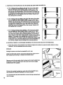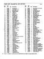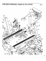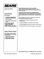
1
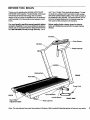
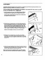
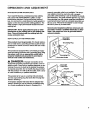
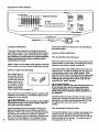
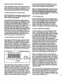
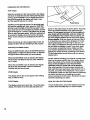
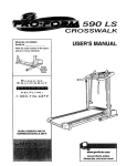
EXPANSE
0ooo
0-I0 _H o 2.0HP• PROGRAMMABLE
SPEED/INCUNE
Model No. 831.297452
Serial No.
The serial number can be found in
the location shown below. Write the
serial number in the space above.
F[O|l|
FO
x
U
E: R
I P
C i _ E:
Ivl
F__ N
Ill
Be|
T
_ I
HF---LPLINE!
1-800-736-6879
_ILCAUTION!:
Reed all precautions end Instructions In this manual before using
this equlpmenL Keep this manual
In e safe place for future reference.
OWNER'S MANUAL
SEARS, ROEBUCK AND CO., HOFFMAN
ESTATES, IL 60179
FULL 90 DAY WARRANTY
For 90 days from the date of pumhase, when proper assembly and maintenance procedures detailed in
the owner's manual are followed, SEARS will, free of charge, repair or replace and install a replacement
part for any defective part, when this treadmill is used in a normal manner.
This warranty does not apply when this treadmill is used for commercial or rentai purposes.
SERVICE IS AVAILABLE SIMPLY BY CONTACTING
TER/DEPARTMENT IN THE UNITED STATES.
YOUR NEAREST SEARS SERVICE CEN-
This warranty gives you specific legal rights, and you may also have other rights which vary from state
to state.
SEARS, ROEBUCK AND CO., DEPT. 817WA,
HOFFMAN ESTATES, IL 60179
2
EXPAN
SE
00
0-10MPHo 2.0HP, PROGRAMMABLE
SPEED/INCUNE
TABLE OF CONTENTS
IMPORTANT
PRECAUTIONS
.................................................................
BEFORE YOU BEGIN ........................................................................
ASSEMBLY ................................................................................
OPERATION AND ADJUSTMENT
.............................................................
TROUBLE-SHOOTING
AND STORAGE ........................................................
CONDITIONING GUIDELINES ...............................................................
PART LIST ...............................................................................
EXPLODED DRAWING ........................................................
ORDERING REPLACEMENT PARTS ..................................................
4
5
6
7
11
13
14
'.............
15
Back Cover
AWA RNING:
Before beginning this or any exercise program, consult your physician. This Is
especially Important for persons over the age of 35 or persons with pre-existing health problems. Read all
Instructions before using. SEARS assumes no responsibility for personal Injury or property damage sustained by or through the use of this product.
3
IMPORTANT
PRECAUTIONS
WARNING:
To reduce the risk of burns, fire, electric shock or injury to persons, read the following Important precautions and Information before operating the treadmill.
1. Position the treadmill on a level surface, with at
least 8 feet of clearance behind the treadmill.
Do not place the treadmill near water, outdoors
or on any surface that blocks an air opening.
Do not operate where aerosol products are
used or where oxygen Is being administered.
2. When connecting the power cord (see PLUGGING IN THE POWER CORD on page 7), plug
the power cord directly into a grounded clrcuif
capable of carrying 12 or more amps. No other
appliance should be on the same circuit. Keep
the power cord away from heated surfaces. If
an extension cord Is needed, use only a 14gauge generel-purposa cord of five feet or less
in length with a three-wire conductor.
.
.
Never move the walking belt while the power is
tumed off. Do not operate the treadmill If the
power cord or plug is damaged, or If the treedmill is not working properly. (See BEFORE YOU
BEGIN on page 5 if the treadmill is not working
properly.)
Wear appropriate exercise clothing when using
the treadmill; do not wear loose clothing that
could become caught in the treadmill. Always
wear athletic shoes; never use the treadmill
with bare feel wearing only stockings or in
sandals. Athletic support clothes are recommended for both men and women.
•5. The pulse sensor is not a medical device.
Various factors, including the user's movement
while exercising, may affect the accuracy of
heart rate readings. The pulse sensor Is Intended only as an exercise aid In determining heart
rats trends In general.
6. Never start the treadmill while you are standing
on the walking belt. Always hold the handrail
when exercising on the treadmill.
7. Never allow more than one person on the treadmill at a time. The treadmill should not be used
by persons weighing more than 250 pounds.
8. Keep small children away from the treadmill at
all times.
9. Never leave the treadmill unattended while it is
running. Always remove the safety key when
the treadmill is not In use.
10. Never drop or insert any object into any opening.
11. To reduce the possibility of overhsatlng, do not
operate the treadmill continuously for longer
than I hour.
12. The treadmill is capable of high speeds. Adjust
the speed in small increments to avoid sudden
jumps in speed.
13. Use the treadmill only as described In this manual.
14. Always unplug the power cord before performing the maintenance and adjustment procedures described In this manual. Never remove
the safety cover unless Instructed to do so by
an authorized service representative. Servicing
other than the procedures in this manual
should be performed by an authorized service
representative only.
SAVE THESE INSTRUCTIONS
4
BEFORE YOU BEGIN
Thank you for selecting the SEARS LIFESTYLEPP
EXPANSE 1000 treadmill. The EXPANSE 1000 treadmill blends advanced technology with innovative
design to let you enjoy an excellent form of cardiovascular exemlee in the convenience and pdvacy of your
home.
until 7 p.m. Central Time (excluding holidays). To help
us assist you, please note the product model number
and serial number before calling. The model number of
the treadmill is 831.297452. The serial number can be
found on a decal attached to the treadmill (see the
front cover of this manual for the location).
For your benefit, read this manual carefully before
using the treadmill. If you have additional questions,
please call our Customer Service Department toll-free
at 1-800-736-6879, Monday through Saturday, 7 a.m.
Before reading further, please review the drawing
below and familiarize yourself with the parts that are
labeled.
Safety Key/Clip
FRONT
Foot Rails
Power Cord
BACK
Circuit Breaker
On/Off Switch
Rear Roller
Adjustment Belts
RIGHT SIDE
Rear Leg Pad
Note: The rear leg pad may mark some types of linoleum. Mild household cleaning agents will remove any marks.
5
ASSEMBLY
Assembly requires two people. Set the treadmill in a cleared area and remove all packing materials. Do not
dispose of the packing matedals until assembly is completed.
THE FOLLOWING
TOOLS ARE REQUIRED FOR ASSEMBLY: The Included 7/32" allen wrench
and your own adjustable
wrench
_:;;;:=:::::::_.
1. Insert the square end of one of the Upright Bushings (98) into
the square hole in the right side of the treadmill Frame (45).
Insert the other Upright Bushing into the hole in the left side of
the treadmill Frame (not shown).
98
45
2. With the help of a second person, raise the Right Upright (18)
and the Left Updght (not shown) to a vertical position. Align the
hole in the lower end of the Right Updght with the hole in the
side of the Frame (45). Insert an Upright Bolt (22), with a Flat
Washer (15), into the Right Upright, and tighten the Bolt into the
Frame. Tighten the Bolt that is already in the Right Upright.
Attach the Left Upright (not shown) in the same manner.
15
45
3. W'dhthe help of a second person, raise the Left and Right
Handrails (7, 14) as shown. Insert a Handrail Bolt (1) into each
• of the Uprights (3, 18), and tighten the Bolts with the 7/32" Allen
Wrench (71).
3
4. Remove the paper backing from the Wrench Clip (62). Press the
Wrench Clip onto the Frame (45) in the indicated location. Press
the 3/16" Allen Wrench (61) into the Wrench Clip.
Make sure that all parts are tightened before using the treadmill.
Note: Cover the floor underneath the treadmill for protection.
61
62
6
22
OPERATION
MAINTENANCE-FREE
AND ADJUSTMENT
WALKING
BELT
Your treadmill features a maintenance-free walking
belt coated with PERFORMANT LUBE TM, a highperformance lubdcant. Dudng the first few hours of
use, it is normal for a small amount of white powder to
appear on the foot rails andthe walking platform. The
white powder is high-performance lubricant from the
walking belt.
IMPORTANT: Never apply silicone spray or other
substances to the walking belt or the welklng plstform, They will deteriorate the walking belt end
cause excessive wear.
HOW TO PLUG IN THE POWER CORD
properly grounded outlet is not available. The temporary adapter should be used only until a properly
grounded outlet (Drawing 1) can be installed by a qualified electrician. The green colored dgid ear, lug, or the
like extending from the adapter must be connected to
a permanent ground such as a propedy grounded outlet box cover. Whenever the adapter is used it must
be held in place by a metal screw.
Some 2-pole receptacle outlet box covers are not
grounded, Contact • qualified electrician to determine if the outlet box cover is grounded before
using an adapter.
1
Grounded
Box
This product must be grounded. If it should malfunction or break down, grounding provides a path of least
resistance for electdc current to reduce the risk of electric shock.
This product is equipped with a cord having an equipment-grounding conductor and a grounding plug. Plug
the power cord Into an appropriste outlet that is
properly Installed and grounded in accordance
with all local codes and ordinances.
DA NG ER:
Improper
connection
ofthe
equipment-grounding conductor can result in a risk of
electric shock. Check with a qualified electrician or serviceman if you are in doubt as to whether the product
is propady grounded. Do not modify the plug provided
with the product--if it will not fd the outlet, have a proper outlet installed by a qualified electrician.
2
Grounded
Box
Grounding Pin
Grounding
Plug
This product is for use on a nominal 120-volt circuit,
and has a grounding plug that looks like the plug illustrated in Drawing 1.
A temporary adapter that looks like the adapter illustrated in Drawing 2 may be used to connect this plug
to a 2-pole receptacle as shown in Drawing 2 if a
Lug
7
DIAGRAM OF THE CONSOLE
Safety Key
CONSOLE OPERATION
retum to the minimum incline level. This will calibrate
the incline system.
The heart of the treadmill is the state-of-the-art programmable console. The console offers beth manual
and progremmable modes, and features four independent displays to provide continuous exemise feedback.
Please read these Instructions carefully before
operating the console.
Note: If there is a thin sheet of clear plastic on the face
of the console, remove it before operating the console.
HOW TO TURN ON THE POWER
If the safety key is in
the console, remove
it. Make sure that the
on/off switch near the
power cord is in the
"on" position. Plug in
the power cord (see
HOW TO PLUG IN
Position
=On"
J
THE POWER CORD on page 7).
Step onto the foot rails of the treadmill. Locate the clip
attached to the safety key, and slide the clip onto the
waistband of your clothing.
a, CAUTION:
oo not stand on the walking
belt when tumlng on the power. Always wear the
clip while using the trsedmill.
8
Insert the safety key into the console. The four displays will be activated and all indicators will light in
sequence. When only the manual and distance indicatore are lit, the console will be ready for operation.
Note: The first time that the safety key is inserted after
the power cord is plugged in, the treadmill will automatically rise to the maximum incline level and then
MANUAL MODE OPERATION
How to Manually Control the Speed
When the power is turned on, the console will be in the
manual mode. For your safety, the walking bait will be
stationary each time the power is tumed on.
The speed range of the walking belt is about 0.5 to 10
miles per hour. To start the walking belt, first slide the
manual speed control to the "reset" position. Then,
slide the control slowly to the right until the walking belt
begins to move at slow speed. Note: Each time the
walking belt Is started, the control must first be
moved to the "reset = position.
A CAUTION:
After the manual speed con-
trol is moved, there will be a pause before the
walking belt begins to move. Adjust the speed
slowly until you are familiar with the operation of
the treadmill.
Hold the handrail and step carefully onto the moving
walking belt. Change the speed of the walking belt as
desired by moving the manual speed control. To stop
the walking belt, move the control to the "reset"
position.
How to Manually Change the Incline
To vary the intensity of your exercise, the incline of the
treadmill can be changed by pressing the INCLINE
buttons. Simply hold down one of the buttons until the
desired incline level is reached. The incline range of
the treadmill is 2% to 12%.
PROGRAMMABLE MODE OPERATION
In the programmable mode, the console will automatically control either the speed of the walking belt or the
incline of the treadmill, according to programs you create. Follow the four steps below to create a program.
1. Select the WALK, RUN or INCLINE Mode
Press the MODE button repeatedly to select the WALK,
RUN or INCLINE mode. An Indicator will light to show
which mode you have selected.
If you select the WALK mode, the console will automatically control the speed of the walking belt during
the program, and the speed range will be about 1 to 5
mph; if you select the RUN mode, the console will
automatically control the speed of the walking belt, and
the speed range will be about 2 to 10 mph; if you
select the incline mode, the console will automatically
control the incline of the treadmill, and the incline range
will be 2% to 12%. Note: If you select the WALK or
RUN mode, the incline can be manually controlled during the program by pressing the INCLINE buttons. If
you select the INCLINE mode, the speed can be controlled by moving the manual speed control.
2. Program Eight Speed or Incline SeEings
The program is divided into eight equal time pedods,
called segments. If you selected the WALK or RUN
mode, you should now program a different speed setting for each of the segments. If you selected the
INCLINE mode, you should program a different incline
setting for each of the segments. The settings can be
programmed using the eight programmable controls on
the left side of the console (see the drawing below).
,,==== _,= _=
-,_s-
Segment Indicators
w........
I=_k.b
|
0-III-II1ll
I1ll
I-III-1 2
3 4
5
6 7
8oo
I
il
,hLhl,i
/
r,i r'_
The programmable control numbered 1 is for the first
segment, the control numbered 2 is for the second
segment, the control numbered 3 is for the third segment, and so forth. Move each programmable control
up or down to program the desired speed or incline
setting. A sample program is shown above. This program will begin with a low speed or incline setting. The
setting will then increase dudng the second and third
segments, decrease dudng the fourth segment,
increase dudng the fifth and sixth segments, and decrease dudng the seventh and eighth segments. An
infinite vadety of settings can be programmed.
Note: The program should begin and end with low
settings to provide warm-up and cool-down periods. Do not set adjacent programmable controls
too far apart; If the speed changes too rapidly, you
may lose your balance and fall.
3. Set the Program Time
Press the TIME SET buttons to set the length of time
that you want the program to last. The length of time is
shown in the TIME display. Each time one of the buttons is pressed, the length of time will change by 4
minutes. The buttons can be held down to set the
length of time rapidly. The program can be set for a
minimum of 4 minutes, up to a maximum of 96 minutes.
4. Press the PROGRAM STARTButton
To start the program, press the PROGRAM START
button. The first segment indicator will begin to flash,
and the treadmill will automatically adjust to the speed
or incline setting of the first programmable control. (If
yo.uselected the INCLINE mode, move the manual
speed control to the =reset" position. Then, slide the
control to the dght until the walking belt begins to
move.) Hold the handrails, step carefully onto the walking belt and begin exemising. The time remaining in
the program will be shown in the TIME display. When
one-eighth of the total length of time you set has
elapsed, the second segment indicator will begin to
flash, and the treadmill will automatically adjust to the
speed or incline setting of the second programmable
control. The program will continue in this manner until
the eighth segment indicator is flashing, and no time
remains in the TIME display. The walking belt will then
slow to a stop and the program will be completed.
Note: If you selected the WALK or RUN mode, the
incline of the treadmill can be controlled dudng the program by pressing the INCLINE buttons. The speed of
the walking belt can be adjusted, if desired, by moving
the programmable control below the flashing segment
indicator. If you selected the INCLINE mode, the
speed of the walking belt can be controlled dudng the
program by moving the manual speed control. The
incline of the treadmill can be adjusted, if desired, by
moving the programmable control below the flashing
segment indicator.
If you wish to stop the program before the program has
been completed, press the MODE button. The console
will then be in the same state as if the program had
been completed. After the program is completed, the
console can be switched to a different mode by repeatedly pressing the MODE button.
9
OPERATION OF THE DISPLAYS
•TIME Display
when the console is in the manual mode, this display
will show the total time that the waJkingbell has been
moving. (If the treadmill is run for longer than g9 minutes and 59 seconds, the display will reset to zero
and the treadmill will slow to a stop.)
If desired, a time goal san be sot. To set a time goal,
first stop the walking bell Next, press the TIME SET
buttons to set the length of time that you plan to exercise. Each time one of the buttons is pressed, the time
goal will change by I minute. The buttons san be held
down to set a time goal rapidly. While the walking belt
is moving, the display will count down the time goal.
When no time remains, the walking belt will slow to a
DISTANCE/CALORIES Display
thumb on the pulse sensor as shown above. The pulse
sensor is pressure-acfivatod. Fully press down the
sensor. Do not press too herd, or the elrcutetlon In
your thumb will be restricted, and your pulse will
not be detected. Next, slightly raise your thumb until
the heart-shaped indicator next to the PULSE display
flashes stsodily. Hold your thumb at this level. After 5
to 10 seconds, your pulse will be displayed. If the displayed pulse appears to be too high or too low, or if
your pulse is not displayed, lift your thumb off the sensor and allow the display to reset. Press down again
on the sensor as described above. Make sure that
Press the MODE button below the DISTANCE/CALORIES display to select the desired mode. An indicator
will light to show which mode you have selected.
your thumb is positioned as shown, and that you are
applying the proper amount of pressure to the sensor.
Try the pulse sensor several times until you become
familiar with it.
stop.
When the console is in the programmable mode, the
display will show the time remaining in the program.
When the DISTANCE mode is selected, the display
will show the total distance that you have walked or
run, in miles.
This display shows the current speed of the walking
belt, in miles per hour.
Another method of finding your pulse is to gently press
down on the sensor until the top of the sensor is just
above the surface of the console. Do not press too
hard, or the elreuletlon In your thumb will be
restricted, and your pulse will not be detected.
After a few seconds, the heart-shaped indicator will
flash each time your heart beats. After another 5 to 10
seconds, your pulse will be displayed. If your pulse is
not displayed, make sure that your thumb is positioned
as shown, and that you are applying the proper
amount of pressure to the sensor. Remember to stand
still while measuring your pulse.
PULSE Display
HOW TO TURN OFF THE POWER
This display shows your heart rate. To use the pulse
display, first stand on the foot roils and place your
To tum oft the power, remove the safety key from the
console. Store the safety key in a secure location.
When the CALORIES mode is selected, the display
will show the approximate number of nutritional
Calories that you have bumod.
SPEED display
"10
TROUBLE-SHOOTING
AND STORAGE
Most treadmill problems can be solved by following the simple steps below. Find the symptom that
applles, and follow the steps listed. If further aeelstance !s needed, call our Customer Servlce Department
toll-free at 1-800-736-6879, Monday through Saturday, 7 a.m. untll 7 p.m. Central Time (excludlng holldays).
1. SYMPTOM: THE POWER DOES NOT TURN ON
a. Make sure that the power cord is plugged into a properly grounded outleL (See HOW TO PLUG IN THE
POWER CORD on page 7.) If an extension cord is needed, use only a 14-gauge general-purpose cord of
five feet or less in length.
b. After the power cord has been plugged in, make sure that the safety key is fully inserted Into the console.
Various indicators on the console should light. (See HOW TO TURN ON THE POWER on page 7.)
c. Check the circuit breaker located on the treadmill near the
power cord. If the switch prOtmdee as shown, the circuit breaker has tripped. To reset the circuit breaker, wait for five minutes and then press the switch back in.
d. Check the on/off switch located on the treadmill near the
power cord. The switch must be in the ON position.
Tripped
_
Reset
o.
Position
2. SYMPTOM: THE POWER TURNS OFF DURING USE
a. Check the circuit breaker located on the treadmill near the power cord. If the circuit breaker has tdpped (see
the drawing above.), wait for five minutes and then press the switch back in.
b. Make sure that the power cord is plugged in.
c. Remove the safety key from the console. Reinsert the safety key fully into the console. Vadous indicators on
the console should light.
d. Check to make sure the on/off switch is in the ON position. (See 1. d. above.)
e. If the treadmill still will not run, please call our Customer Service Department.
3. SYMPTOM: THE PULSE SENSOR DOES NOT WORK PROPERLY
a. Make sure that your thumb is properly positioned (see PULSE Display on page 10), and that you are applying the proper amount of pressure to the sensor. Stand still while measuring your pulse.
4. SYMPTOM: THE WALKING BELTSLOWS WHEN WALKED ON
a. If an extension cord is needed, use only a 14-gauge general-purpose cord of five feet or less in length.
b. If the walking belt is overtightened, treadmill performance may
decrease and the walking belt may be permanently damaged.
Remove the safety key and UNPLUG THE POWER CORD.
Using the 3/16" allen wrench, turn both rear roller adjustment
bolts counterclockwise, 114 of a turn. When the walking belt is
propedy tightened, you should be able to lift each side of the
walking belt 3-4 inches off the walking platform. The center of
the walking belt should just touch the walking platform. Be careful to keep the walking belt centered. Plug in the power cord,
insert the safety key and run the treadmill for a few minutes.
Repeat until the walking belt is propedy tightened.
c. If the walking belt still slows when walked on, please call our Customer Service Department.
11
S. SYMPTOM: THE WALKING BELTIS OFF-CENTER OR SLIPS WHEN WALKED ON
a. If the walking belt has shifted to the left, first remove the safety
key and UNPLUG THE POWER CORD. Using the 3/16" allen
wrench, turn the left rear roller adjustment bolt clockwise, and
the right bolt countemlockwise, 1/4 of a tum each. Be careful not
to overtighten the walking belt. Plug in the power cord, insert the
safety key and run the treadmill for a few minutes. Repeat until
the walking belt is cantered.
b. If the walking belt has shifted to the right, first remove the safety
key and UNPLUG THE POWER CORD. Using the 3/16" allen
wrench, tom the left rear roller adjustment bolt counterclockwise,
and the right belt clockwise, 114 of a tum each. Be careful not to
ovedighten the walking belt. Plug in the power cord, insed the
safety key and run the treadmill for a few minutes. Repeat until
the walking belt is centered. "
C.
If the walking belt slips when walked on, first remove the safety
key and UNPLUG THE POWER CORD. Using the 3/16" allen
wrench, tum both rear roller adjustment bolts clockwise, 1/4 of a
tum. When the walking belt is correctly tightened, you should be
able to lift each side of the walking belt 3-4 inches off the walking
platform. The canter of the walking bolt should just touch the
walking platform. Be careful to keep the walking belt centered. Plug
in the power cord, insed the safety key and run the treadmill for a
few minutes. Repeat untilthe walking bolt is properly tightened.
b
c
6. SYMPTOM: THERE IS A NOTICEABLE DIFFERENCEIN THE INCLINE RANGE OF THE TREADMILL
a. Raise the incline of the treadmill to its maximum height and continue to press the incline button for three
seconds. This will recalibrata the incline system.
STORAGE
Unplug the power cord when the treadmill is not in use.
Using the 7/32" allen wrench, remove the bolt from the upper end of
each upright (see drawing 1). Rotate the handrails down.
Remove one bolt and washer from the lower end of each upright (see
drawing 2). Loosen the other bolt in the lower end of each upright.
Carefully lower the uprights.
Remove the upright bushing from each side of the treadmill frame
(see drawing 3). Keep the hardware in a secure location.
It is recommended that the treadmill be covered during extended periods of storage.
12
3
Remove
CONDITIONING
GUIDELINES
The following guidelines will help you to plan your
exercise program. Remember that proper nutrition
and adequate rest are essential for successful results.
I WARNING:
..,or.
beginning this or
any exercise program, consult your physician.
This Is aspeclally Important for Individuals over
the age of 35 or Individuals with pre-exlotlng
health problems.
EXERCISEINTENSITY
To maximize the benefits of exercising, it is important
to exercise with the proper intensity. The proper intensity level can be found by using your .heart rate as a
guide. For effective aerobic exercise, your heart rata
should be maintained at a level between 70% and
85% of your maximum heart rata as you exemise.
This is known as your training zone. You can find your
training zone in the table below.
AGE
UNCONDmONED
TRAINING ZONE
(BEATS/MIN)
CONDITIONED
TRAINING ZONE
(BEATS/MIN)
20
138-167
133-162
25
136-166
132-160
• 30
135-164
136-158
35
134-162
129-156
40
132-161
127-155
45
131-159
126.153
50
129-156
124-150
55
127-155
122-149
60
126.153
121-147
65
125-151
119-145
70
123-150
118-144
75
122-147
117-142
80
120-146
116.140
85
118-144
114-139
During the first few months of your exercise program,
keep your heart rate near the low end of your training
zone as you exercise. After a few months of regular
exercise, your heart rate can be increased gradually
until it is near the middle of your training zone as you
exercise.
You can measure your heart rate using the pulse
sensor on the console. Exercise for at least four minutss, and then measure your heart rate Immediately.
If your heart rate is too high, decrease the Intensity of
your exercise. If your heart rate is too low, increase
the intensity of your exercise.
A WARNING:
_,.
pulse sensor Is not a
medical device. Various factors, including your
movement during exercise, may affect the accuracy of heart rate readings. The sensor Is Intended
only as an exercise aid In determining heart rate
trends In general.
WORKOUT GUIDELINES
Each workout should consist of three basic pads: a
warm-up, 20 to 30 minutes of training zone exercise,
and a cool-down. Warming up prepares the body for
exercise by increasing circulation, delivering more
oxygen to the muscles and raising the body temperature. Begin each workout with 5 to 10 minutes of
stretching and light exercise to warm up. Then,
increase the intensity of your exercise to raise your
heart rate to your training zone for 20 to 30 minutes.
Breathe regularly and deeply as you exemise--never
hold your breath. Finish each workout with 5 to 10
minutes of stretching to cool down. This will increase
the flexibility of your muscles as well as help to
decrease soreness and other post-exercise problems.
To maintain or improve your condition, plan three
workouts each week, with at least one day of rest
between workouts. After a few months of regular exercise, you may complete up to five workouts each week,
if desired.
The key to success is to make exercise a regular and
enjoyable part of your everyday life.
13
PART LIST--Model
Key
No.
1
- 2
3
4
5
6
7
8
9
10
11
12
13
14
15
16
17
18
19
20
21
22
23
24
25
26
-- 27
28
29
30
31
32
33
34
35
36
37
38
39
40
41
•42
43
44
45
46
47
48
49
50
51
52
53
54
55
56
14
Part
No.
Qty.
119994
2
119793
1
120298
1
124009
2
114005
2
111869
6
1
115816
1
120727
119038
1
121812
1
113203
2
013141
5
1
119696
115817
1
4
014132
122106
1
119816
1
120297
1
112609
1
014127
3
119824
1
013430
4
113204 • 2
118148
1
013162
15
120909
1
108080
8
123308
1
109365
1
019084
1
109382
1
119163
1
031229
1
117806
2
052014
2
013547
3
5
012149
111430
2
116677
1
2
012056
119416
1
122346
1
015071
4
1
105989
NSP
1
012152
1
116892
1
119375
2
114270
2
115523
1
109370
1
102959
1
102955
1
110407
1
013028
4
116601
1
No. 831.297452
Description
Handrail Bolt
Front Safety Cover
Left Upright
Black Flat Washer
Handrail Endcap
Cage Nut
Left Handrail
Console
Safety Key/Clip
Wire Harness
6" Cable Loom
Console Screw
Console Plate
:
Right Handrail
Flat Washer
Front Roller/Pulley
Front Left Endcap
Right Upright
Front Roller Adj. Bolt
Roller Adjustment Washer
Front Right Endcap
Upright Bolt
12' Cable Loom
Belt Guide
Safety Cover Screw
Choke Bracket
Screw
Electronics Bracket
Choke
Grommet
Circuit Breaker
On/Off Switch
Power Cord
Front Wheel Bolt
Front Wheel
Incline Leg Bolt/Motor Lock Bolt
Lock Nut
Console Cage Nut
Incline Leg
Wheel Nut
Safety Cover Bracket
Power Beard
Plastic Stand-Off
Controller-Power Board Wire
Frame
Small NUt
Incline Bracket
Incline Motor Bolt
Incline Motor Spacer
Incline Motor
Incline Optic Disk
Small Bolt
Optic Switch
Rear Leg Pad
Endcap Screw
Right Rear Endcap
R495^
Key
No.
Pert
No.
Qty.
57
58
59
60
61
62
63
64
65
66
67
68
69
70
71
72
73
74
75
76
77
78
79
80
81
82
83
84
85
86
87
88
89
90
91
92
93
94
95
96
97
98
99
100
#
#
#
#
#
#
#
#
#
#
#
102633
016357
016029
105444
123355
016028
107503
109788
116600
121157
100691
122347
119995
121158
045017
119026
120867
122644
113278
118017
100994
120713
110447
105477
121164
122369
119289
119769
013438
120866
118153
120168
054023
119815
116927
116926
013088
122812
014157
104188
014117
123303
122332
115872
101951
101799
109407
114011
107771
102246
102634
118201
112083
112083
122410
1
3
1
2
1
2
1
1
1
2
8
1
2
1
1
1
1
1
1
1
2
1
1
2
1
1
2
1
2
10
1
1
3
1
1
1
8
1
1
2
1
4
2
1
1
1
1
1
1
1
1
1
1
1
1
Description
Optic Switch Wire Harness
8" Cable Tie
4" Cable Tie
Rear Roller Adj. Bolt
3/16" Allen Wrench
Wrench Clip
Motor Swivel Bolt
Rear Roller
Left Rear Endcap
Foot Rail Mounting Track
Platform Screw
Walking Platform
Handrail Bolt
Left Foot Rail
7/32, Allen Wrench
Power Inlet Bracket
Flange Nut
Motor Mount Bracket
Pulley/Flywheel/Fan
Motor Belt
Motor Bolt
Motor
Controller
Motor Nut
Rear Safety Cover
Walking Belt
Deck Bracket
Safety Cover Wire Harness
Handrail Pivot Bolt
Small Mounting Screw
Reed SwltclVSensor Wire
Extension Wire
Wire Clip
Right Foot Rail
Tie Block
Wire Tie
Bracket Screw
Motor Tension Washer
Switch Star Washer
Cover Washer
Upright Star Washer
Upright Bushing
Upright Spacer
Strain Relief
8" Black Wire, 2 Female
8" Black Wire, Male/Female
4" Black Wire, 2 Female
4t Black Wire, Male/Female
8" White Wire, Male/Female
8" White Wire
8" Green Wire, Female/Ring
8" Red Wire, Male/Female
8" Blue Wire, 2 Female
8" Blue Wire, Male/Female
Owner's Manual
Note: "#" indicates a non-illustrated part. Specifications are subject to change without notice.
EXPLODED DRAWING--Model
No. 831.297452
R49s^
T
9
85
76
1\
77
5
71
L/
78
37
74
17
98
88
15
29
87 19
26
15
82
70
66
81
99
2
/
90
,
22
44
42
.,31
,32
33
SF_ARS"
The model number and serial number of your SEARS
LIFESTYLER e EXPANSE 500 treadmill are listed on a decal
attached to the frame. See the fmnt cover of this manual to find the
location of the decal.
Model No. 831.297452
If you find that:
All replacement pads are available for immediate purchase or
special order when you visit your nearest SEARS Service Center, or
the Service Department of most SEARS Stores. To request service
or to order parts by telephone, call the toll-free numbers listed at the
left.
• you need help seeembling or
operating the EXPANSE loo0
When requesting help or service, or ordering pads, please be prepared to provide the following information:
QUESTIONS?
• a part Is missing
• or you need to schedule repair
eervice
• The NAME OF THE PRODUCT (SEARS LIFESTYLER ®
EXPANSE 1000)
call our toll-free HELPLINE
• The MODEL NUMBER OF THE PRODUCT (831.297452)
1-800-736-6879
• The PART NUMBER OF THE PART (see page 14 of this manual)
Monday-Saturday,
7 am--7 pm
Central Time (excluding holidays)
• The DESCRIPTION
REPLACEMENT
OF THE PART (see page 14 of this manual)
PARTS
If parts become worn and need
to be replaced, call the following
toll-free number
1-800-FON-PART
(1-800-386-7278)
SEARS, ROEBUCK AND CO., HOFFMAN ESTATES, IL 60179 USA
Part No. 122410 R495A Printed in USA
© 1995 Sears, Roebuck and Co.