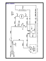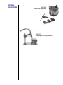
1
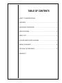
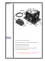
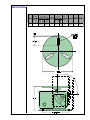
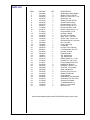
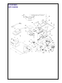
Product Description
#2 Positioner
M.K. Manual Part Number
091-0132
M.K. Form Number
PO/OM-2
NWSA Form Number
1060
Effective with Serial
Number
Voltage Ratings
Printing/Rev. Date
This manual applies to the
following Model Numbers
110 VAC
6/98
127-002
#2 Positioner Turntable
OWNERS MANUAL
16882 ARMSTRONG AVE., IRVINE, CALIFORNIA
92606 TEL (949) 863-1234
FAX (949) 474-1428
SAFETY CONSIDERATIONS
ELECTRIC ARC WELDING EQUIPMENT
CAUTION : READ BEFORE ATTEMPTING INSTALLATION,
OPERATION OR MAINTENANCE OF THIS EQUIPMENT
1-1 INTRODUCTION
This equipment is intended for ultimate application by commercial/industrial users and for operation by
persons trained and experienced in the use and maintenance of welding equipment. Operation should
not be undertaken without adequate training in the use of such equipment. Training is available from many
public and private schools or similar facilities.
Safe practices in the installation, operation and maintenance of this equipment requires proper training
in the art, a careful study of the information provided with the equipment, and the use of common sense.
Rules for safe use are generally provided by suppliers of welding power sources, compressed gas
suppliers, and electrode suppliers. Careful compliance with these rules will promote safe use of this
equipment.
The following Safety Rules cover some of the more generally found situations. READ THEM CAREFULLY.
In case of any doubt, obtain qualified help before proceeding.
1-2 GENERAL PRECAUTIONS
A. Burn Prevention
ELECTRIC ARC WELDING PRODUCES HIGH INTENSITY HEAT AND ULTRAVIOLET RADIANT
ENERGY WHICH MAY CAUSE SERIOUS AND PERMANENT EYE DAMAGE AND WHICH MAY
DAMAGE ANY EXPOSED SKIN AREAS.
Wear helmet with safety goggles or glasses with side shields underneath, appropriate filter lenses or
plates (protected by clear cover glass). This is a must for welding or cutting (and chipping) to protect the
eyes from radiant energy and flying metal. Replace cover glass when broken, pitted, or spattered.
Medical first aid and eye treatment. First aid facilities and a qualified first aid person should be available
for each shift unless medical facilities are close by for immediate treatment of flash burns of the eyes and
skin burns.
Wear protective clothing - leather (or asbestos) gauntlet gloves, hat, and high safety-toe shoes. Button
shirt collar and pocket flaps, and wear cuffless trousers to avoid entry of sparks and slag.
Avoid oily or greasy clothing. A spark may ignite them.
Flammable hair preparations should not be used by persons intending to weld or cut.
Hot metal such as electrode stubs and work pieces should never be handled without gloves.
Ear plugs should be worn when working on overhead or in a confined space. A hard hat should be worn
when others work overhead.
B. Toxic Fume Prevention
Adequate ventilation. Severe discomfort, illness or death can result from fumes, vapors, heat, or oxygen
enrichment or depletion that welding (or cutting) may produce. Prevent them with adequate ventilation.
NEVER ventilate with oxygen.
Lead-, cadmium-, zinc-, mercury-, beryllium-bearing and similar materials, when welded or cut, may
produce harmful concentrations of toxic fumes. Adequate local exhaust ventilation must be used, or each
person in the area, as well as the operator, must wear an air-supplied respirator. For beryllium, both must
be used.
Metals coated with or containing materials that emit toxic fumes should not be heated unless coating is
removed form the work surface, the area is well ventilated, or the operator wears an air-supplied respirator.
Work in a confined space only while it is being ventilated and, if necessary, while wearing an air-supplied
respirator.
rails, electrical wires, or welding circuits. They can produced short circuit arcs that may lead to a serious
accident. (See 1-3C)
ICC or DOT marking must be on each cylinder. It is an assurance of safety when the cylinder is properly
handled.
Identifying gas content. Use only cylinders with name of gas marked on them; do not rely on color to identify
gas content. Notify supplier if unmarked. NEVER DEFACE or alter name, number, or other markings on
a cylinder. It is illegal and hazardous.
Empties: Keep valves closed, replace caps securely; mark MT; keep them separate from FULLS, and return
promptly.
Prohibited use. Never use a cylinder or its contents for other than its intended use, NEVER as a support
or roller.
Locate or secure cylinders so they cannot be knocked over.
Passageways and work areas. Keep cylinders clear of areas where they may be stuck.
Transporting cylinders. With a crane, use a secure support such as a platform or cradle. Do NOT lift
cylinders off the ground by their valves or caps, or by chains, slings, or magnets.
Do NOT expose cylinders to excessive heat, sparks, slag, and flame, etc. that may cause rupture. Do not
allow contents to exceed 55 degrees C (130 degrees F.) Cool with water spray where such exposure exists.
Protect cylinders, particularly valves from bumps, falls, falling objects, and weather. Replace caps securely
when moving cylinders.
Stuck valve. Do NOT use a hammer or wrench to open a cylinder valve that cannot be opened by hand.
Notify your supplier.
Mixing gases. NEVER try to mix any gases in a cylinder.
NEVER refill any cylinder.
Cylinder fittings should never be modified or exchanged.
3. Hose
Prohibited use. Never use hose other than that designed for the specified gas. A general hose identification
rule is: red for fuel gas, green for oxygen, and black for inert gases.
Use ferrules or clamps designed for the hose (not ordinary wire or other substitute) as a binding to connect
hoses to fittings.
No copper tubing splices. Use only standard brass fittings to splice hose.
Avoid long runs to prevent kinks and abuse. Suspend hose off ground to keep it from being run over, stepped
on, or otherwise damaged.
Coil excess hose to prevent kinks and tangles.
Protect hose from damage by sharp edges, and by sparks, slag, and open flame.
Examine hose regularly for leaks, wear, and loose connections. Immerse pressured hose in water; bubbles
indicate leaks
Repair leaky or worn hose by cutting area out and splicing. Do NOT use tape.
4. Proper Connections
Clean cylinder valve outlet of impurities that may clog orifices and damage seats before connecting
regulator. Except for hydrogen, crack valve momentarily, pointing outlet away from people and sources of
ignition. Wipe with a clean, lintless cloth.
Match regulator to cylinder. Before connecting, check that the regulator label and cylinder marking agree,
and that the regulator inlet and cylinder outlet match. NEVER Connect a regulator designed for a particular
gas or gases to a cylinder containing any other gas.
Tighten connections. When assembling threaded connections, clean and smooth seats where necessary.
Tighten. If connection leaks, disassemble, clean, and retighten, using properly fitting wrench.
equipment can fatally shock a person whose body becomes a conductor. DO NOT STAND, SIT, LIE, LEAN
ON, OR TOUCH a wet surface when welding without suitable protection.
To protect against shock:
Keep body and clothing dry. Never work in damp area without adequate insulation against electrical shock.
Stay on a dry duckboard, or rubber mat when dampness or sweat cannot be avoided. Sweat, sea water,
or moisture between body and an electrically HOT part - or grounded metal - reduces the body surface
electrical resistance, enabling dangerous and possibly lethal currents to flow through the body.
1. Grounding the Equipment
When installing, connect the frames of each unit such as welding power source, control, work table, and
water circulator to the building ground. Conductors must be adequate to carry ground currents safely.
Equipment made electrically HOT by stray currents may shock, possibly fatally. Do NOT GROUND to
electrical conduit, or to a pipe carrying ANY gas or a flammable liquid such as oil or fuel.
Three-phase connection. Check phase requirement of equipment before installing. If only three-phase
power is available, connect single-phase equipment to only two wires of the three-phase line. Do NOT
connect the equipment ground lead to the third (live) wire, or the equipment will become electrically HOT
- a dangerous condition that can shock, possibly fatally.
Before welding, check ground for continuity. Be sure conductors are touching bare metal of equipment
frames at connections.
If a line cord with a ground lead is provided with the equipment for connection to a switch box, connect the
ground lead to the grounded switch box. If a three-prong plug is added for connection to a grounded mating
receptacle, the ground lead must be connected to the ground prong only. If the line cord comes with a threeprong plug, connect to a grounded mating receptacle. Never remove the ground prong from a plug, or use
a plug with a broken ground prong.
2. Connectors
Fully insulated lock-type connectors should be used to join welding cable lengths.
3. Cables
Frequently inspect cables for wear, cracks, and damage. IMMEDIATELY REPLACE those with excessively
worn or damaged insulation to avoid possibly lethal shock from bared cable. Cables with damaged areas
may be taped to give resistance equivalent to original cable.
Keep cable dry, free of oil and grease, and protected from hot metal and sparks.
4. Terminals and Other Exposed Parts
Terminals and other exposed parts of electrical units should have insulating covers secured before
operation.
5. Electrode Wire
Electrode wire becomes electrically HOT when the power switch of gas metal-arc welding equipment is ON
and welding gun trigger is pressed. Keep hands and body clear of wire and other HOT parts.
6. Safety Devices
Safety devices such as interlocks and circuit breakers should not be disconnected or shunted out.
Before installation, inspection, or service of equipment, shut OFF all power, and remove line fuses (or lock
or red-tag switches) to prevent accidental turning ON of power. Disconnect all cables from welding power
source, and pull all 115 volts line-cord plugs.
Do not open power circuit or change polarity while welding. If, in an emergency, it must be disconnected,
guard against shock burns or flash from switch arcing.
Leaving equipment unattended. Always shut OFF, and disconnect all power to equipment.
Power disconnect switch must be available near the welding power source.
#2 Positioner - Owner's Manual
Page 13
TABLE OF CONTENTS
SAFETY CONSIDERATIONS
FEATURES ......................................................................................... 1
OPERATING PROCEDURE ............................................................... 1
SPECIFICATIONS............................................................................... 2
PARTS LIST ........................................................................................ 3
#2 POSITIONER PARTS DIAGRAM ................................................... 4
WIRING SCHEMATIC ......................................................................... 5
OPTIONAL ACCESSORIES ............................................................... 6
WARRANTY
#2 Positioner - Owner's Manual
Page 8
FEATURES
Tilt Release/
Locking Knob
Stepless
Speed
Control
Foot Control
Rheostat
Fuse
Forward/
Reverse
Switch
High/
Low
Range
Switch
OPERATING
PROCEDURE
1. Connect positioner to 115 VAC power source.
2. Connect welding ground cable to grounding lug assembly on positioner.
3. Set high/low range switch to proper position.
4. Set forward/reverse switch to proper position.
5. Establish desired speed setting using the rheostat on the positioner.
6. Depress foot control to activate positioner.
NOTE: Failure to attach the welding ground cable to the grounding lug assembly
will result in damage to the positioner electrical circuit.
#2 Positioner - Owner's Manual
Page 1
SPECIFICATIONS
Model
2A
#2 Positioner - Owner's Manual
Standard
Turntable
Diameter
7"
Turntable
Capabilities
with Balanced Load
Turntable Turntable
Horizontal Vertical
100 lbs.
30 lbs.
Degree
Tilt
0º to
90º
Speed
Range
R.P.M.
Low
High
0.25-6
4-10
Ground
Capacity
AMPS
Motor
Shipping
Weight
Transmission
250
115VAC
50/60 Hz
23 lbs.
Gear
Belt
Page 2
PARTS LIST
ITEM
1
2
3
4
5
6
7
8
9
10
11
*12
13
14
15
16
17
18
19
20
21
22
23
24
25
26
27
28
29
30
31
32
33
34
*35
36
37
38
39
40
41
PART NO.
002-0065
331-0102
330-0038
401-0016
331-0100
003-0044
401-0013
325-0131
117-0009
321-0071
511-0043
431-0590
342-0039
333-0051
321-0083
117-0016
403-0006
151-0001
152-0058
345-0043
843-0001
341-0054
405-0043
159-0001
159-0013
331-0176
461-0006
511-0041
501-0039
324-0215
445-0005
505-0089
325-0230
331-0004
431-0591
002-0084
213-0010
271-0009
431-0539
176-0003
153-0147
QTY
1
3
2
1
3
1
1
1
1
4
1
1
3
1
4
1
1
1
1
2
1
2
1
1
1
1
1
1
2
4
1
1
4
4
1
1
1
1
1
1
7
DESCRIPTION
Welded Assy Base Support
Washer Flat 1/2 SAE Stl.
Shdr. Scr. 3/8-16 1/2 x 1-1/4
Knob Alum. 2 In.
Washer Flat 3/8 SAE Stl.
Ground Terminal Assy
Rheostat Knob 1.2 O.D.
Pan Hd. Scr. #6-32 x 1/4
Rheost. 250 Ohm. 50W
Set Scr. Cup #10-32 x 1/4
Pully-Gearbelt 1.4 P.D.
Housing - Mach'd
Nut Jam 1/2-13 Brass
Wshr. Lock 1/2 Int. Star
Set Scr. Cap. 1/4-20 x 3/8
Rheostat Foot Ctrl. 100 Ohm
Dial 1 to 8 Blk.
Fuse 2 Amp 3 Ag.
Fuseholder
Hex Nut 3/8-16 Flexlock
Line Cord Mold. 18/3 8 Ft.
Hex Nut 15/32-32
Plate-Model No.
Tog. Switch Spdt.
Tog. Switch Dpdt.
Washer Brass .50 x 1.125
Gearbelt 70T 140 x L037
Pulley-Gearbelt 2.801 P.D.
Bearing-O/F Bushing
FHMS Scr. 10-24 x 1-1/4
Stud Thrd. 1/2-13 Brass
Shaft-Turntable Dr.
Pan Hd. Scr.10-32 x 3/4
Washer Flat #10 Stl.
Cover-Mach'd
Welded Assy. Ground Cable
Gearmotor 115V. Ser. 576:1
Insulator Pad Asbest.
Turntable Mach'd 7 In.
Brush, CU, Concaved
Wire Nut-71B
* Must be purchased together under P/N 003-0042 (housing with cover).
#2 Positioner - Owner's Manual
Page 3
#2 POSITIONER
PARTS DIAGRAM
#2 Positioner - Owner's Manual
Page 4
WIRING SCHEMATIC
#2 Positioner - Owner's Manual
Page 5
OPTIONAL
ACCESSORIES
005-0039
Dual purpose 3-jaw chuck
005-0075
T-racking kit for fixture positioning
#2 Positioner - Owner's Manual
Page 6
Effective April 1, 1998
This warranty supersedes all previous MK Products warranties and is
exclusive, with no other guarantees or warranties expressed or implied.
LIMITED WARRANTY - MK Products,Inc.,Irvine,California warrants
that all new and unused equipment furnished by MK Products is
free from defect in workmanship and material as of the time and
place of delivery by MK Products. No warranty is made by MK
Products with respect to trade accessories or other items
manufactured by others. Such trade accessories and other items
are sold subject to the warranties of their respective manufacturers,
if any.
MK Products’ warranty does not apply to components having
normal useful life of less than one (1) year, such as relay points,
wire conduit, tungsten, and welding torch parts that come in
contact with the welding wire, including nozzles, nozzle insulators,
and contact tips where failure does not result from defect in
workmanship or material.
In the case of MK Products’ breach of warranty or any other duty
with respect to the quality of any goods, the exclusive remedies
therefore shall be at MK Products’ option: (1) repair; (2) replacement;
(3) where authorized in writing by MK Products, the reasonable
cost of repair or replacement at our Irvine, California plant; or (4)
payment of or credit for the purchase price (less reasonable
depreciation based upon actual use) upon return of the goods at
customer’s risk and expense. Upon receipt of notice of apparent
defect or failure, MK Products shall instruct the claimant on the
warranty claim procedures to be followed.
As a matter of general policy only, MK Products may honor an
original user’s warranty claims on warranted equipment in the
event of failure resulting from a defect within the following periods
from the date of delivery of equipment to the original user:
1. Torches and Weldheads ........................................ 1 year
2. All Other Equipment ............................................. 3 years
3. Repairs ................................................................... 90 days
MK PRODUCTS, INC.
16882 ARMSTRONG AVENUE
IRVINE, CA 92606
TEL (949) 863-1234
FAX (949) 474-1428
Classification of any item into the foregoing categories shall be at
the sole discretion of MK Products. Notification of any failure must
be made in writing within 30 days of such failure.
A copy of the invoice showing the date of sale must accompany
products returned for warranty repair or replacement.
All equipment returned to MK Products for service must be
properly packaged to guard against damage from shipping. MK
Products will not be responsible for any damages resulting from
shipping.
Normal surface transportation charges (both ways) for products
returned for warranty repair or replacement will be borne by MK
Products, except for products sold to foreign markets.
ANY EXPRESS WARRANTY NOT PROVIDED HEREIN AND
ANY
IMPLIED
WARRANTY,
GUARANTY,
OR
REPRESENTATION AS TO PERFORMANCE, AND ANY
REMEDY FOR BREACH OF CONTRACT WHICH, BUT FOR
THIS PROVISION, MIGHT ARISE BY IMPLICATION,
OPERATION OF LAW, CUSTOM OF TRADE, OR COURSE OF
DEALING, INCLUDING ANY IMPLIED WARRANTY OF
MERCHANTABILITY OR OF FITNESS FOR PARTICULAR
PURPOSE, WITH RESPECT TO ANY AND ALL EQUIPMENT
FURNISHED BY MK PRODUCTS, IS EXCLUDED AND
DISCLAIMED BY MK PRODUCTS.
EXCEPT AS EXPRESSLY PROVIDED BY MK PRODUCTS IN
WRITING, MK PRODUCTS ARE INTENDED FOR ULTIMATE
PURCHASE BY COMMERCIAL/INDUSTRIAL USERS AND FOR
OPERATION BY PERSONS TRAINED AND EXPERIENCED IN
THE USE AND MAINTENANCE OF WELDING EQUIPMENT
AND NOT FOR CONSUMERS OR CONSUMER USE. MK
PRODUCTS WARRANTIES DO NOT EXTEND TO, AND NO RESELLER IS AUTHORIZED TO EXTEND MK PRODUCTS’
WARRANTIES TO ANY CONSUMER.
FORM : LW-8
DATE : April 1, 1998
M.K. PRODUCTS, INC.
16882 ARMSTRONG AVE.
IRVINE, CALIFORNIA 92606
TEL (714) 863-1234 FAX (714) 474-1428
M.K. Part Number 091-0132
Printed in the U.S.A.