1
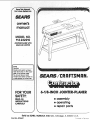
MODEL NO.
113.232210
JOINTER/PLANER WITH
LEGSAND MOTOR
Serial
Number
Model and serial numbers
may be found on the backside of the jointer base.
You should record both
model and serial number in
a safe place for future use::
tHl' '
't
i
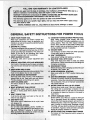
FORYOUR
6-!!E-INCH
JOmHTER'PL ER
SAFETY:
READALL
INSTRUCTIONS
CAREFULLY
• assembly
e operating
e repair parts
"L""
Luu'u .
Sold by SEARS, ROEBUCK AND CO., Chicago,
Part No. SP5447
--
,,__'_
iL 6068,4 U.S.A_
?r_
ir_ r._,,_c_r_
NTER/PLANER
due to a
of charge.
CONTACTING THE NEAREST SEARS SER-_
while this product is used in the United States.
rights, and you may also have other rights which
ROEBUCK AND CO. Dept: 698/731A. Sears Tower, Chicago, IL 60684
;:;I
GENERAL SAFETY iNSTRUCTiONS
_
_
i
KNOW;YOUR POWER TOOL
Read and understand the owner_ manual and
labels affixed to the tool. Learn its application and
limitationsas well as the specific potential hazards
peculiar to this tool.
2; GROUNDALL TOOLS
. This tool is equipped with an approved 3-conductor
::i:_cordanda 3-pr0nggr0unding type :plugto fit the
proper grounding
receptacle. The green conductor _inthe cord: is:the: grounding wire, Never
" i _ connect the green wire to a live terminal.
_3; KEEPGUARDS
INPLACE
: i_i _ln wo[kingl order, and in: proPer adjustment and
!. alignment;
I::'_
...........
i
;_:':'
;_'_....
_.
_:i!
::_:;:::_i
_::_
i:::::
_:';i;:
SH0_ ICHIL_ROOF
_
i_maste_switchesilby removing star-_
5ring tools where: children Can_ get::
;_'_::_
::_i;_: i_
::i_I:_ :
job better and safer at the rate for
it was designed::
:i : :
_:
:::
J
FOR POWER TOOLS
12, USE SAFETYGOGGLES [HEAD PROTECTION)
Wear safety goggles (must comply with ANSI
Z87.1 ) at all times. Everyday eyeglassess are not
safety glasses. They only have impact resistant
lenses. Also, use face or dust mask if cutting operation is dusty, and ear protectors (plugs or muffs)
during extended periods of operation.
13, SECURE WORK
Use clamps or avise tO hold work when practical.
It frees both hands to operate tooll
14, DON'T OVERREACH
" Keep proper footing and balance at all times.
15. MAINTAIN TOOLS WITH CARE
Keep tools sharp and clean for best and safest
:performance. Follow instructionsfor lubricating and
NEVERSTAND ON TOOL OR ITS STAND ;i _i::
._
Sed0us!njU_could
occur if the toot is tipped or ff
CUtting:tool is accidentally contacted: Do not'
:: ::_:, ::store, materials above or near the tool such that it
is;tieCessaryto standon the to01 or its;stand to
:reachthern_ ::;
......
: :
_2o;: CHECK DAMAGED PARTS
1:
Before furtheruse of the tool, a guard or other part
:: ::i thatJs damagedshouid
be carefully checked to
:_::_i:::;:::::i::i
_;Don;t for_i:io01s 0_ _achment to do a job it was
:_:_: ensure::that it:wi!l operate properly and perform its
i_::::
intended Tunction:Check for alignment ol" moving
_::: ::::_::i_:::
....
.... _ :_.... ' ...... : parts, bfndlngor mowng parts, breakage of parts,
"_
'
_"
: ..... .........
mountin .....
.... conditions that may anect
"
_;::::_ _ _".......
:::_:;_!;::D6
_ "': .........
ov_: :_nec_ies
_:or::....................
:: :::
g; ana any other
_::
:';:_i_:i;;:r_,_': _ri_+:_
_n t*.t _.nht_inrnov . : :
=tsoperat;on. A guardor other part that =sdamaged
_:' _ ......... .............
...................
: ......
_ ......_ e nded ;:
:_::: • :::should
be properly
.........:
.... repaired or rep aced
::: 21;: NEVERLEAVETOOLRUNNING
UNATTENDED
; :::
=_:';:R_i
_ge .............
:el_w: ..........
;
.....' ...............
Turn power off Don't leave toot untl it comes to a
complete stop.
::!
....
..... nal.........
..... "n...........
"..... for jointer-planer
add=tBo
sa fsty
structaons
BEFORE
Safety is!a combination ofcommon sense, staying alert
and knowing flow your jointer-pianer works_.....
BEFORE
1. Inspect your jointer-pfaner.
USING THE JOINTER-PLANER:
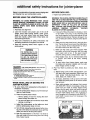
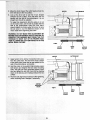
WARNING: THE 2-INCH JOINTER-PLANER PULLEY
AND THE 2-1/2 INCH MOTOR PULLEY FURNISHED
WILL RUNTHE CUTTER HEAD AT ABOUT 4300 RPM
WHEN USED WITH A 3450 RPM MOTOR. USE OF
DIFFERENT TYPES OF PULLEYS OR MOTORS
WILL CHANGE THIS SPEED AND COULD CAUSE
JAMMING,
BINDING,
KICKBACK,
THROWN
BLADES OR OTHER DANGERS.
WARNING: TO AVOID MISTAKES THAT COULD
CAUSE SERIOUS, PERMANENT INJURY, DO NOT
PLUG THE JOINTER-PLANER IN UNTIL THE FOLLOWING STEPS HAVE BEEN SATISFACTORILY
COMPLETED.
1. Assembly and alignment.
2. Learn the function and proper use of the on-off
switch, fence slide locking handle, cutter guard,
depth of cut hand wheel, locks and stops, fence
bevel lock handle, ouffeed table, infeed table and
hold-down/push-blocks.
a. If any part of this jointer-p_aner is missing, or bent,
or has failed in any way, or any electrical parts
don't work properly, turn the jointer-planer off and
unplug the jointer-planer. Replace damaged, missing, or failed parts before using the jointer-planer
again.
3. Read and understand all safety instructions and
operating procedures throughout the manual.
4. Read the following labels which appear on the
jointer-planer:
b. Make sure the cutter head turns in the right direction. The top should move toward the infeed table.
Call your Sears Service Department for help if
the cutter head turns the wrong way.
WARNING
c. Make sure the cutter guard works properly. With
the switch off and key removed, pull the cutter
guard open and let go. If the guard doesn't
smoothly swing closed, contact Sears Service,
THESTARTING
RELAYIN THIS
JOINTER
ISAGRAVITY
SENSmVE
TYPE.NEVER
TURNTHEPOWER
ON UNTILTHE JOINTERHAS
BEEN
MOUNTED
ONTHELEGSET
ANDISINUPRIGHT
POSITION.
d. Keep blades sharp. Dull or knicked blades tend
to "pound" and chew at the wood, causing
kickbacks.
r
JlDANGER|
FOR YOUR OWN SAFETY: KnowThis Tool!
Read and Understand
the Owner's
Manual
Befo=_
Using
• Wear Safety Gogg]es complying
with ANSI Z87,1.
S Always
Make sure it springs
Use Cutter
Head Gua,d.
AIways=se_,iveg.=d.
,
• Use HoldlDown
Push Blocks
_: Jointlngmsteri,l
narrower
Machine_
shut automaticaily:
_i ::: : ,: ::i
for:
:
than
3 inches
or
,
....
P_.tng,.a_r_,_thi.,,.,tha.
__n=,_s. :_:
!n=h.:
_
i
......
WHEN INSTALLING
JOINTER-PLANER:
:
....
: :: :
_
:
;:
_
_ _ :_ :
:
e. To avoid injury from thrown pieces, make sure
the blades are properly installed and the cutter
blade wedge, screws are tight.
2. Plan Your Work to protect your eyes, hands, face,
ears.
....
:
a_.
Bef0re trying a new or fittte used operation, carefully pianyour hand placement. Make sure you
have proper hold-down/push-blocks,
jigs, fix'
tures,.stops, etc. ready to use.
i : i:
_: : : ':i_ i'"
_OR MOVING
_ ,
EACH USE:
:
THE
key removed.
c. Wear safety goggles (not glasses) that comply
with ANSI Z87.1 (shown on package). Using any
power tool can result in foreign objects being
thrown into the eyes, which can result in permanent eye damage. Safety goggles are available
at Sears retail catalog stores. Use of glasses or
use of goggles not in compliance with ANSI Z87.t
could result in severe injury from breakage of the
eye protection.
11 To avoid injury:fromltmexpected jOinter-planer or
workpiece imovement;. ;
i:
.....
:i::
a. Use the jointer-ptaner indoors °na firm level surface in a well lit area,
b. Place the jointer-planer where:
i. there is plenty of room for moving the workpiece through the entire cut.
ii. no one must stand in line with the wood while
planing or jointing it.
C;
Adjust the jointer-planer so the tables are level
and the jointer-ptaner does not rock.
d.
Turn off and unplug the jointer-planer before moving it to a new area. To avoid back injury, get help
when you need to tift the jointer-planer.
e,
Bolt the jointer-planer to the floor if it tends to
slip, walk, slide or tip over during work like cutting
long, heavy boards.
Do layout, assembly or set up work on the tabte
only while the jointer-planer is off and the switch
WEAR
3
YOUR
:IL: ¸.
using only one hold-down/push-block to feed
the wood, do not put your other hand on the
jointer-planer, workpiece, or hold-downtpushblock.
cut FREEHAND. Guide your work_
piece s01idiy against the if;nCe: and
table:top.:
"
:
:
Small ori!thin workpieces can kick back when they tip
0ver onthe tab esor: into the Cutter head, To aV0id head
contact or :Workpiece kickback:
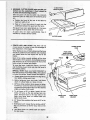
3_ Make sure all clamps and locks are tight and
there is no excessive play m any parts.
l,. Adjust the depth of cut to between 1/32 and t/16
of an inch for best results in most operations. A
deep cut makes feeding the wood harder and
can cause the wood to kickback. To be sure you
wilf make a depth of cut you planned, always
lower the infeed table slightly farther than
you wanted. Then, raise the table to the
desired depth.
m. Before using the jointer-planer, clear the table of
all objects not needed to feed the workpiece.
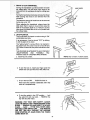
.....i. Never joint or bevel workpieces less than
3/4:inch:wide: or 1t4 inch thick_
ii.,:AlWays USe::the;i hold-downtpush-blocks
when j6ir_ting: or: beveling wood: narrower
than3 inches;
.:
4:: i When Planing:
......... ; i.: Nevei; piar}e; wood thinner than 1/2 inch.
:....... i:_ii.: Always use hold-down/push-blocks when
:i:: ' ri::;:_:;::ii :planing wood thinner than3 inches:,
f::i,i_To'::avbidilr
skof! hearing damage, wear ear plugs
.:Or muffs during extencied periods of Operation.
:..... g. T0:aV0id:be{n_j:!Suddeniy pulled i nto the blade:
i :I::I.:D0
not wear: gi0vesi: :: .....
.... ;:'::.2. Removeaii:']ewelry and::looseCi0thing,
.... 3. :Tieback
long hair_: :_
4_ Roll long sleeves above the elbow_' :
h_ To avoid inju[yfrom accidental startingll always
turn- switch off_ remove switct_ key and: unplug
jointer-planer before installing or removing, any
;blade, accessory or attachment, or making any
adjustments.
i. To avoid an electrical shock, make sure your fingers do not touch the metal prongs on the plug
when inserting or removing the plug to or from a
live outlet.
j. To :avoid burns or other fire damage, never use
the jointer-planer near flammable liquids, vapors
or gases.
n, :Toavoid injuryfrom unsafe accessor es,.use only
recommended accessories.
WHENEVER
ISRUNNING:
JOINTER-PLANER
WARNING: DON'T LET FAMILIARITY (GAINED
FROM FREQUENT
USE OF YOUR JOINTERPLANER) CAUSE A CARELESS MISTAKE. ALWAYS
REMEMBER THAT A CARELESS FRACTION OF A
SECOND: IS SUFFICIENT TO INFLICT SEVERE INJUR_
1. Make: sure bystanders are clear of the tool and
workpiece.
2. Before actually cutting with the jointer-planer, let it
run for a while. If your jointer-ptaner makes an unfamiliar noise or if it vibrates excessively, stop immediately. Turn the jointer-ptaner off. Unplug the
jointer-planer. Do not restart until finding and correcting the problem.
3. To avoid injury from slips, stalls or kickback, feed
the workpiece into the jointer-ptaner only fast enough
to let the tool cut without bogging down or binding.
4. Before freeing jammed material, turn switch off, remove switch key, unplug the jointer-planer and wait
for all moving parts to stop.
5. Never leave the jointer-planer while it is running or
before it has come to a complete stop. Remove the
switch key and store it in a safe place.
,
glossary of terms for Woodworking
1, JOINTING
The removal Ofwood along the edge
Of a piece Of wood so as to make the edge both
straight and smooth.
8. REVOLUTIONS PER MINUTE (R.RM.)...
The
number of turns completed by a spinning object in
one minute.
2. PLAN! NG... Removing wood from the widest surface of a board so as to make it flat and smooth.
g_
3. WORKPIECE...
The piece of wood on which the
cutting operation is being performed.
4. DEPTH OF CUT,.. A term used to indicate how
deep into the workpiece the cutter knives will cut,
10. FENCE...
attached to the jointer-planer in a more
or less vertical position .... helps support and guide
the workpiece as workpiece is pushe_l across the
cutter head.
5, INFEED TABLE... The section of the table upon
whichthe workpiece is placed before being pushed
into the cutter.., its height is adjustable which allows the operator to select the depth of cut into
the workpiece,
6. OUTFEEDTABLE.,.
The section of a table which
supports the workpiece after it passes over the
cutter.
,
,
nl
11. FREEHAND...
trying to use the toot without holding the workpiece firmly against the fence and table.
This can let the workpiece twist and kick back.
12. LEADING END... the end of the workpiece which
is pushed into the cutting tool first.
13. TRAILING END...
the blades.
HOLD-DOWN/PUSH-BLOCKS,..
They are required for your own safety,., they are used to hold
thin or narrow workpiece down against the table
and fence when planing or jointing.
iii
,11,,11 ii ,1
,
i
KICKBACK,..
a kickback occurs when the
operator loses control of the workpiece causing it
to be kicked back toward him by the rotating cutter
knives.
iiip_!!!,,
!,,1_11
iii
i
iiiiiiiii
..................
the workpiece end last cut by
ii
i
II
II
I
II
I
table of contents
Page
Guarantee .................................
2
Installing the Fence
"
General Safety Instructions for Power Tools ......
2
Installing Belt Guard and Sliding Guard ........
Additional Safety Instructions for Jointer/Planer .... 3
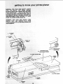
Getting to Know Your Jointer/Ptaner ............
Glossary of Terms of Woodworking
.
5
• Basic Jointer/Planer Operations ...............
Electrical Connections ..................
,.:.._.:. :6
Maintenance. ...........
. ...................
Unpacking and Checking Contents ........ i:._ .... ,. :8
Sharpening Cutter Knives
Location and Function of Controls. ;.: _. _._ ,, _ i_i_:11
Installing (Replacing) Cutter Guard Spring
Assembling the Steel Legs .... ._............ _ii..
,:._12 , Lubrication
Installation of Drive Belt .... i ..... .... ..... _...:_
::'.,; .._ 13
Trouble Shooting ...........................
Mounting the Jointer/Pianer ,., .:.. o::_:::
_. i_., 15
Repair Parts ..............................
Checking Cutter Knives and Screws .
_ .:.. :,. 16
Page
17
18
20
27
31
34
34
35
36
38
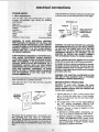
FIRE HAZARDS, OR DAMAGE TO THE TOOL, USE
::PROPER:CIRCUIT
PROTECTION. YOUR JOINTER,
PLANER ISWIRED ATTHEFACTORY F0R 120V OPERATION. CONNECTTO::A i20V 15-AMP, BRANCH
CIRCUIT AND USE::A: 15-AMP, TIME DELAY FUSE
OR CIRCUIT BREAKER.
IF NOT PROPERLYGROUNDED, THIS POWER TOOL
CAN , CAUSE ELECTRICAL
SHOCK,PARTICU.
: looks;like beloW,
WARNING: TO MAINTAIN PROPER TOOL GROUNDING WHENEVER THE OUTLET YOU AR E PLANNING
TO USE FOR THIS POWER TOOL IS OF THE TWO
PRONG TYPE, DO NOT REMOVE OR ALTER THE
GROUNDING PRONG IN ANY MANNER. USE AN
ADAPTER AS SHOWN AND ALWAYS CONNECT
THE GROUNDING PRONG TO KNOWN GROUND.
CAUTION: To avoid motor damage, this motor
should be blown out or vacuumed frequently to
prevent sawdust build-up which will interfere with
normal motor ventilation.
3-PRONG
PLUG
PROPERLY
GROUNDED
OUTLET
,
GROUNDING
PRONG
;
a' 3-conductor cord
Underwriters _
Connect this tool to a 120V, 15-Amp branch circuit
with a 15-Amp time delay fuse or circuit breaker.
Failure to use the proper size fuse can result in dam*
age to the motor.
If the motor fails to start, turn the power switch to
the "OFF" position immediately. UNPLUG THE
TOOL. Refer to the "MotorTrouble-Shooting Chart."
Freq uent "blowing':' of fuses or tripping of circuit
breakers may result if:
a._ MOTOR IS OVERLOADED--Overloading
can
oCcur if you feed too rapidly into cutter knives.
b,: MOTOR:CIRCUIT
IS FUSED DIFFERENTLY
:FROM RECOMMENDATIONS--Always
follow
: instructions for the proper fuse/breaker. Do not
; :use:a fuse/breaker of greater capacity without
consulting a qualified electrician.
c. LOWVOLTAGE.Althoughthe
motorisdesigned:: WIRE: SIZES
f0i'i operation:on
the voltage and frequency
specified:on motor nameplate, normal loads will
be handled safelyonvoltages notmore than 10%
above or below the nameplate voltage. Heavy
loads, however, require that voltage at motor terminals equals the voltage specified on nameplate:
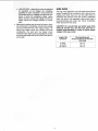
The use of any extension cord wilt cause some loss of
power, To keep this to a minimum and to prevent overheating and motor burn-out, use the table below to
determine the minimum wire size (A.W.G,) extension
cord. Use only 3 wire extension cords which have 3
prong grounding type p_ugs and 3-pole receptacles
which accept the tools plug.
4. Most motor troubles may be traced to loose or incorrect connections, overloading, reduced input voltage
(such as small size wire in the supply circuit) or to
overly long supply circuit wire. Always check the
connections, the load and the supply circuit
whenever motor fails to perform satisfactorily. Check
wire sizes and length with the Wire Size Chart shown
to the right.
• i ¸¸¸ :....
CAUTION: For circuits that are farther away from
electrical service box, the wire size must be increased proportionately in order to deliver ample
voltage to the saw motor.
• •
7
Length of the
Conductor
Wire Sizes Required
(American Wire Gauge Number)
120V Lines
0-25 Ft.
26.50 Ft.
51-100 Ft.
No. 16
No. 14
No, 12
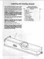
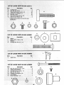
,el:1i 3;232210! 6,1/8 :JOINTER
E MISSINGPARTSARE OBTAINED
ICORRECTLY.
0il that:isapplied to all unpainted
TOXIC REACTION.
E,:_NAPTHA OR SIMILAR
SOL:VE S;
:: Applya coat of paste:wax t0the table.
Wipe all partsth0rough
y w tha clean, dry cloth.
WARNING:- FOR:YOUR OWN SAFETY, NEVER CONNECTP LU G::TOi_
POWER SOURCE 0 UTLET UNTIL
ALLASSEMBLY STEPS ARE COMPLETEiANDYOU
HAVE READiANDUNDERSTAND
THE SAFEW AND
OPERATIONAL :iNSTRUCTIONS,
i
: L--,!
¸: _
• :•:
L•_••I•/
••
••
/
:
.
.
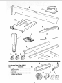
item
;
:::Description _
A JointerBase,,;!i.
;..,
..; .......
B Fence .:; ,.:i..
, ......................
C;Push Bocks...:ii.::i_.i
:..:...
;i; ;...
D Siding Fence Guard...
;.....:
........
E Belt Guard ..........................
F Owner's Manual ......................
G Legs ...................
............
H Top Side Stiffener ....................
I Bottom Side Stiffener .................
J Top End Stiffener ....................
K Bottom End Stiffener ..................
L Loose Parts Bag #507711 .............
M Loose Parts Bag #508210 .............
N Loose Parts Bag #508092 .............
Qty.
1
1
, 2
1
t
1
4
2
2
2
2
1
1
1
E
\
K
i' ;•••i i•'_::•
•i• ¸¸I¸:•:
•ii_i!!i:
¸ •_•_•
O
List of Loose Parts in Bag #508210
Item
Description
O ,V"Belt
..
i. .....................
P Siding Guide Rod. ...............
Q Pulley....
:: .......................
R Lock Knob ._.: ........
................
:S iLoose Parts Bag. ....................
: (#508091and #508093)
,...
Qty.
1
1
1
1
2
9
G
0
i
i
ii
i
iii ii
!
LIST OF LOOSE
Item :i:_::
i:i
PARTS: IN BAG #508091
:Description: :
_H .::::Spacer :: ::.!_
_::_.
Qty.
ill::. ...... ..... :. i
:i
Washer380x
19/64x7/64,
.:. .....:,,:;;..
1
*3
Retainerli
,.
_/,:!_:i ,.,'
i
*::K . Carriage:Bolt3/8-16
x2.1/2,
i.....
:.;:. ;_ 1
O
: L
Description
!:*L
Switch Key, ...........
.:.....i::.
..... -.. 1:......
i[]
iJJ
LIST OF LOOSE
Item
PARTS IN BAG #508093
Description
Qty.
G
M
,Lllltppnltl_lllWUlWllimltlli!g
0
N
S
90° AND 45 °
FENCETI_
SCALE
7
FENCE STOPS _
1 DEPTH OF CUT
HANDWHEEL
5 SLIDING GUARD
KNOB
3 CUTTER
GUARD
2 ON-OFF
_: :i_ ::!!: ::;: i
SWITCH
4 FENCELOCK
KNOB
LOCATION
:
AND FUNCTION
1. Depth of cut handwheeh
_
OFCONTROLS
i: : _
_:
5. Sliding Guard Knob:
By,turning the handwheel you can controihow much
wood will be removed from the workpiece.
2. On-Off Switch_
_:
Turns the tool on and off.
3. Cutter Guard:
Helps protect the operator from the sharp knives on
the cutterhead,.
It is spring loaded so it automatically keeps the cutterhead covered before, during,
and after a cutting operation,..
It must always be
used,
:
Allows the fence to be repositioned at any location
from the front to the rear of the tables and to
be locked at that position. To unlock--turn the knob
counterclockwise.To lock--turn the knob clockwise,
6. 90° and 45 ° Fence Stops:
When adjusted properly, these stops provide a
method for quickly moving the fence to a 90 ° or 45 °
position from the table,
7, Fence Tilt Scale:
Helps the operator accurately and quickly position
the fence at any angle between 45" and 90 °.
4. Fence Lock Knob:
Allows the fence to be: repositioned and locked at
any angle from 45 ° to 90 °. To lock--turn the knob
clockwise:. To unlock--turn
the knob counterclockwise.
11
EDGE:OF: :
NCH THICK:
......
_ : :
• ....... ......
_::: :: :
PERFECTLY STRAIGHT
:\
,sCREWDRiVEF
\_
/
"_:'/
;_
_
il
I
:
, ....
: :7116'!SOCKET
,,2SOC<E,
.
.....
_
_
SQUARE
_
-
I(____
I:
: : _
!
:
I[_, ,'_'-_
DRAW LIGHT ..... i
I'#'il
LINE ON BOARD
L!_
ALONG THIS EDGE '_
I:
1/2":OPEN END WRENCH
7ii6": OPEN END:WRENCH
9/16;';OPEN END WRENCH
:
i
,
'%
:6_':SOCKET EXTENSION
I
COMBINATION
:
.......
: '
.....
9/16" SOCK_
I
_
.....
/
/
/
I
,\J, --
.... I
: iN
/
SHOULD BE NO GAP OR OVERLAP HERE WHEN
[
SQUARE IS FLIPPED OVER IN DOTTED POSITION
3/4"OPENENDWRENCH
3/8"..16
HEX NUT
Q
LEVELING FOOT
THEJOINTER
: :
i
:
PLANER;:::::::!
©Q
leg set, hand
TRUSS
HEAD SCREW
LOCK
WASHER
114"-20
HEX NUT
STIFFENER
STII
\
j,ll,_l
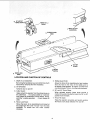
INSTALLING
ADJUSTING
DRIVE BELT AND
BELT TENSION
MOTOR
CUTTER HEAD
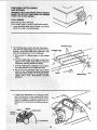
WARNING: DO NOT LETANY PART OFYOUR BODY
TOUCH THE CUTTER HEAD. tT CONTAINS VERY
SHARP CUTTER KNIVES WHICH COULD CUT YOU
BADLY.
1. Fromthe loose parts find the drive belt and the putiey.
From the packing material used in the jointer box,
find two (2) large pieces of styrofoam.
SPECIAL NOTE: When turning the JointeriPtaner upside down do not put the weight of the Jointer/Planer
on the guard or the guard may be broken. Do not roll
the JointedPlaner over because this may also break
the guard.
2. Put the two pieces of styrofoam on the floor and put
the JointeriPlaner upside down on the cardboard as
illustrated.
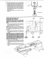
WARNING: DO NOT TURN: THE MOTOR ON UNTIL
:THE JOINTERiPLANER
IS COMPLETELY ASSEM:
:
BLED AND TURNED RIGHTSIDE: UP WITHiTHE i : i_: :
LEVELING FEET SETTING AGAINSTTHE FLOOR_ :_:
IF THIS WARNING IS NOT FOLLOWED THE MOTOR
MOTOR
AND START SWITCH MAY BE BURNED OU_'YOUI
MOUNTING
COULD ALSO BE BADLY CUT BYTHE VERY SHARP =
BOLTS
KNIVES ON THE CU_ER HEAD_ :: ', :'
:
3. Locate the two motor: mounting bolts on the underside of the j0inter. Using a 1/2, _Socket, 6" extension,
and a Socket wrench loosen these two moto_ mounting bolts.
.........
4. Slide the motor: pUiley onto the motor shaft as illustrated with the set screw side of pulley toward the
jointer,
:
•
MOTOR
PULLEY
i
13
CUTTER
PULLEY
screw,isover the fl,
!: :motor stiaft before tightening set screw.
on the
!
THIS
AOJUST.E.T
.V
MoVING!THE CUTTERHEAD!PULLEY. FAILURE TO
OBSERVE THiS IWARNING MAY CAUSE THE CUTTERHEAD TO MOVE OUT OF ITS: PROPER POSITION ALLOWING THE CUTTER: KNIVES TO HITTHE
'METAL BASE CASTING.
MOTOR
PULLEY
,
,
,
,
DRIVE
BELT
,, ,111
CUTTERHEAD
MOTOR
BOLTS
\
CUTTER
PULLEY
\
.
.,q_DiIiiNim
•
DRIVE
BELT
MOTOR
PULLEY
•14
CUTTER
PULLEY
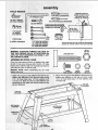
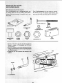
MOUNTING
THE JOINTER/PLANER
1.:From the loose parts find three (3) 3/8-t6 x 3/4" hex
head bOlts, and three (3) 3/8 internal lock washers.
2: Place the teg set on top of the jointer!planer and
align the three (3) mounting holes on the bottom
side of the jointer/ptaner with the holes in the leg
set (see illustration).
3. Place a lock washer on each bolt. Using your fingers,
screw the bolts through the leg set holes and into
the mounting holes in the jointer/planer. Tighten the
bolts securely using a 9/16 inch wrench.
HEX HEAD
BOLT
4. Using a 7/16" socket wrench tighten all nuts and
bolts that hold the leg set together.
5. Get another person to help you turn the jointer right
side up so the leveling feet are against the floor.
I
)
'
>
15
INTERNAL
LOCKWASHER
STRAIGHT
EDGE
OUTFEED TABLE
INFEEDTABLE
--
i
i
i
:
_••: Hi •
e, If cutter knife adjustment is not required, check::
each locking screw on each wedge (5/32" HeX,L
"
wrench): and tighten if necessary. Hold :the2inch
pulley in a stationary position to prevent the Cut;
terhead from turning during this tightening procedure.
WEDGE
CU'I_ERHEAD
i,_,
i_!i_ii
_!_
ii_i
il_ii__,}_i'i
i_!_i_'_¸¸_¸¸_
INSTALLING
FENCE
1. Rotate the cutter guard counterclockwise and place.
the fence on the jointer table as shown.
2.: Locate the following parts from the loose parts bag
and install as shown:
,
One (1) 318-16 x 2-1/2 carriage bolt, one (1) retainer,
one (1) .380x 1-5/32 x 3/32 flat washer, one (1)
spacer, and one (1) knob.
Attach the fence to the jointer as illustrated below.
RETAINER
4. Rotate the cutter guard counterclockwise away from
the fence and then release it. The spnng tension on
the guard must cause it to swing back against the
fence, if the guard does not swing back against the
fence, recheck your assembly procedure. Do not
use the jointer/planer if the guard wilt not automatically swing back against the fence and cover the
cutter head,
SPACER
FLAT WASHER
CARRIAGE
BO_
KNOB
CARRIAGE
BOW
SPACER
FLAT
WASHER
RETAINER
VIEWED
t7
• !!!i....
FROM REAR
\
KNOB
one
One (1)Split Iockwasher 1/2,, two (2) 10-32 x 1/4, Pan.
I-ld_Screws, two (2)#10 External Lock Washers, two
-32 x2-3/4' PaR Hd: SCrews, One (i) Belt Guard.
Illl!lltlllllliflllillllllllllWIIIIIlllltlitltlllll]]
...
PAN HD SCREW 2-314"
SLIDING GUARD
SLIDING GUARD
•KNOB
PLASTIC
WASHER
HEX NUT
112"
©
Os
PAN HD
EXTERNAL
LOCKWASHER #10
BE_
GUARD
LOCKWASHER
1/2"
ROD
1/2" NUT
!
i:
i
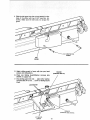
4. Slide the belt guard over the rod and attach it to the
base of the jointer with two 2-3/4" long Pan. Hd.
screws. Make sure the belt does not scrape the
guard.
O
j2-3/4" LONG PAN HD.
SCREW
BE_
GUARD
5. Attach sliding guard to fence with two pa n head
screws and Iockwashers;_ i _ : _
WASHER
.....
(CONCAVE
SIDE UP)
6. Place one Sliding Guard!Washer, concave side
DOWN on support rod.
......
7. Drop sliding guard onto rod .:. place other washer,
concave side UPon rod ;. screw on Sliding Guard
Knob.
LOCKWASHER
WASHER
(CONCAVE
1/4" PAN HD.
SCREW
19
SIDE DOWN)
know your _'ointerwplaner
J;
ID KEEP
F
WH
UP AGAIN
L:
WARNING:
FOR YOUR: OWN SAFETY TURN
SWITCH i_i"OFF":
AND i REMOVE PLUG
FROM
POWER SOURCE OUTLET BEFORE MAKING ANY
ADJUSTMENTS;
4 4S_FENCE
_
STOP
STOP
,
0N-OFF SWITCH.
The on-off switch is shaped to make turning it "ON"
accidentally less likely.
In an emergency, it can be turned "OFF" by striking
it with the palm of the hand.
The "yellow button" is a key. When it is inserted in
the switch lever, the power may be turned ON and
0FE When it is removed, the power cannot be turned
ON.
THIS FEATURE IS INTENDEDTO HELP PREVENT
UNAUTHORIZED
AND
POSSIBLE
HAZARDOUS USE BY CHILDREN AND OTHERS,
a. Insert Key into switch.
NOTE: Key is made of yellow plastic.
b. To turn the tool on, insert your finger under the
switch lever and pull the end of the switch out.
i ii1_
C,
To turn the tool OFF _.. PUSH the lever in.
Never leave the machine unattended until it has
come to a complete stop.
d, To lock the switch in the OFF position..,
hold
the switch IN with one hand ... REMOVE the
key with the other hand.
WARNING: FOR YOUR OWN SAFETY, ALWAYS
LOCK THE SWITCH "OFF" WHEN MACHINE IS NOT
IN USE...
REMOVE KEY AND KEEP IT IN A SAFE
PLACE..,
ALSO . .. IF THE TOOL STOPS UNEXPECTEDLY, TURN SWITCH OFF . . . AND REMOVE
THE KEY. THIS WILL PREVENT THE MACHINE
FROM STARTING UP AGAIN WHEN THE POWER
COMES BACK ON.
21
!:tii:Sji::i
posiwood.
tior
If.guard::does
not return automatically,
ichecked by :a Sears Service :Center.
have it
CUTTER GUARD
"
i ¸
:
•
[i
i
ii
,
SLIDING GUARD
KNOB
\
PUSH DOWN
WHEN LOCKING
FENCE LOCK KNOB
blades. _: .......
Most: of_the Cutting (usually joiniing)wilibe
!i
FENCE
done
45° FENCE
STOP
.. .... with the fence in this posifioni As :the:blades become
OUTFEEDTABLE
:
To tilt fence, loosen the fence 10ck knob and slid:
ing guard knob and pull the stop out; Tilt to desired
angle and tighten both knobs:
:::.:: :
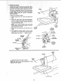
d. To set fence at 90 ° to tables, loosen the
knobs, titt fence so the stop springs back
place. Tilt fence back so the stop rests on
table. Hold fence down on outfeed table
tighten both knobs.
two
into
the
and
FENCE LOCK
KNOB
:.:: e.:i 45_ Fence Stop positions the fence at 450 to the
: .......;::
tables.:
.
to:45t, loosen the two knobs, pu!l 90°
stop rests on the
....
:th
._,:
::
i{i
:::•:i:h
::>::
;T
•:
"•!!ii,:!::::i{)}
:,:,
,i
22
":
:
:/-:,
=i :
:: ::.-
.:
"
FENCE SLIDE
BRACKET
5. FENCE TILT SCALE.
Indicates the ang!e of the fence to the tables: When
the 900 fence stol_ s correct y adjusted; the fence
will be90Q to the table and the scale wil! read 90°_
FENCE
To Check for squareness, place an accurate square
on infeed table and check fence while_locked at 90°
position, MAKE SURE 90 ° STOP IS AGAINST
SLIDE BRACKET.
HEAD
OF
JSQUARE
tf fence is not square to table:
a. Slightly loosen fence lock knob and guard lock
knob.
b. Loosen 90 ° stop screw with small screwdriver
and turn knurled sleeve which will cause fence
to tilt. Turn sleeve in either direction until fence
is square with infeed table.
NOTE: If you cannot square fence by turning
knurted sleeve, loosen three screws "A" and adjust fence square to table.
c. Tighten 90 ° stop iockscrew and both fence lock
knobs.
dr
tNFEED
TABLE
CUTTER
GUARD
SCALE
ADJUSTING
SCREW
If 90 ° reading on tilt scale does not line up with
top surface of the slide bracket, loosen screws
holding scale and move it... tighten screws,
45=STOP
LOCKSCREW
A
TILT
KNURLED
SLEEVE
45 ° STOP
90 _ STOP
45°STOP
KNURLED
SLEEVE
90 ° STOP
SCALE
ADJUSTING
SCREW
90°STOP
SLIDE
BRACKET
FENCELOCK,_ _"
KNOB
INFEED
TABLE
SQUARE
\
FENCE
FACE
e. Adjust 45 ° stop in the same manner.
NOTE: Tilt scale will n_ _require adju_ment if it was
adjusted for 90 ° 0osition.
v
,,,
•
CUTTERGUARD
23
T
MUST ALWAYS:BE PARALLEL TOTHE OUTFEED
TABLE.
ifthe _cut edge or surface of the workpiece is
CROWNED,I it is
indication that the oUTWARD
{_
:_
CONCAVE CUT
._-'_-_
_L--_-!
_
_,
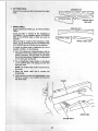
:adjusted.
If thecut edge or surface o{ the workp ece is CONCAVE, it is an indicati0n;that the OUTWARD END
._.-_: of the INFEEDtable is LOW and must be adjusted,
,.
_TO:check the infeed table to determine the "out of
"_...
J
INFEED TABLE LOW
cutter}uard
touches
the:
\
INFEED TABLE
OUTFEED TABLE
::::: :::
:::!_
:: :i::
::::i::
:::_: :
::_!_:i ::¸_
_:!:i:=:_:
'::: ::!::_!:,::_
:i¸_ii :!:_:
::::::
::::::::
::::::::: :
::::::::::::::::::::::::::::::::
the infeed tabi_ SO:it'is pamiiel::to the oui:: : ::::::
:::::
:feed:tab!e Call::be:a:::tme: €onsuming::processl :To::::::
:::Co_ER:Gu:AR_:::
:i
::::_.::
!:i::::
::::::
:::::
::: :complete:the adjustment in as: littletime as possible
':
: : :: ::
:
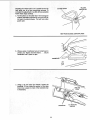
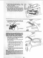
Put:the:yeiiow:on::offswitch:keyinthe rectangular
shaped indentation exposed as you turn the cutter guard counterclockwise. This will hotd cutter
guard open.
:
!
YELLOW
SWIT/CHKEY
f:
....
_'_ _:::_..._
S
L.._--._ _..,_.J___F.,,'_
_-'-'--.:-/7_'_._
-"_"/_ ;/,,_./_
/
VIEW FROM BACKSIDE
JOINTER/PLANER
b. Wrap a peice of cardboard around cutterhead to
protect your fingers and the blades..,
secure
cardboard with a piece of tape.
CARDBOARD
c. Using a 1/2 inch open end wrench; Ioosenthe
Iockboits 1/2 turn under the section of the table
that is low. Loosen no more of the lockboits than
is necessary.
STUD
LOCKBOLTS
25
I/Z'OPEN
END
WRENCH
LEVELING
STUD
•
h the straightedge to make sure the
infeed _tabie :is teveL If it is not, go through the
above Steps :again
.
"
7",
LOCK BOLTS
i•
-i ••-
i
illl
i
i
i
i
ii
ii
i
i
i
i
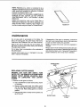
8.1,MOUNTING HOLES FOR AUXILIARY FENCE;
TheSe _holes are proVided so you may attach an
auxiliary fence to the front of the cast iron fence. An
auxiliary fence should be used anytime you joint
boards _/ider than 4-1/2 incheS_The auxiliary fence
should.be, made from a smooth straight board and
cutto a widtPithat witt cause the auxiliary fence tO
be::no more :than 1 inch narrower than the board
being jointed_ i :::
_
!.Attach theaUxiiiary fence as i!lustrated;
MOUNTING
HOLE
AUXILIARY
FENCE
\
\
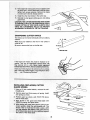
i
basic jointer=pUaner operation
BEFORE
EACH USE
Plan Your Work to protectyour eyes, hands, face, ears.
b. Remove all jewelry and loose clothing.
1. Carefully plan your hand placement. Make sure you
have proper hold-down/push-blocks, jigs, fixtures,
stops, etc. ready to use.
c. Tie back long hair.
d. Roll long sleeves above the elbow,
6. To avoid burns or other fire damage, never use the
jointer-p_aner near flammable liquids, vapors or
gases.
7. To avoid injury from slips and jams:
2. Do layout, assembly or set up work on the table
only while the jointer-planer is off and the switch
key removed.
3. Wear safety goggles that comply with ANSI Z87.1
a. Use this jointer-planer to cut only wood.
b. Plan your hand placement so your fingers will not
be anywhere a sudden slip could cause them to
slide or fall into the cutter head. When using only
one hold-down/push-block to feed the wood, do
not put your other hand on the Jointer-Planer,
workpiece or hold-down/push-blocks.
4, For dusty operations, wear a dust mask along with
safety goggles.
5. Plan your work to match your workpiece:
a. Surface plane warped wood on the concave side
for best results,
b. Don't joint or plane plywood, particle board, other
composition materials or wood that has glue,
paint or varnish on it. Materials like these will
quickly dull the blades.
c. Make sure all clamps and locks are tight and
there in no excessive play in any parts,
8. Adjust the depth of cut to between 1/32 and 1/16
of an inch for best results in most operations. A
deep cut makes feeding the wood harder and can
cause the wood to kickback. To be sure you will
make a depth of cut you ptanned, always lower the
infeed table slightly farther than you wanted. Then,
raise the table to the desired depth.
c. Make sure there are no nails or foreign objects
in the part of the workpiece to be cut.
d. Never cut FREEHAND. Guide your workpiece
solidly against the fence and table top.
Small or thin workpieces can kickback when they tip
over on the table or into the cutterhead. To avoid cutterhead contact or workpiece kickback:
9. Before using the jointer-pfaner, clear the table of
all objects not needed to feed the workpiece.
1. NEVER joint, plane or bevel workpieces shorter
than 12 inches.
10. To avoid injury from unsafe accessories, use only
recommended accessories.
2. When Jointing or Beveling:
a. Never joint or bevel workpieces less than 3/4
inch wide or 1/4 inch thick.
Whenever Jointer-Planer is running
1. Make sure bystanders are clear of the toot and
workpiece.
2,: Before actually cutting with the joiner-planer, let it
run for awhile, tf your jointer-planer makes an unfamiliar noise or if it vibrates excessively, stop immediately. Do not restart untilfinding and correcting
the problem.
b. Always use the hold'down/push-blocks
when
jointing or beveling wood narrower than3 inches.
3_
When Planing:
....
a. Never plane wood thinner than i/2 inch.
b. Always use hoid=down/push_btockswhen planing wood thinner than 3 inches: _ :,
,
To avoid risk of hearing damage, wear ear plugs
or muffs during extended periods of ope!ation.
5, To avoid being suddenly pulled into the blade!
a. Do not wear gloves.
3. To avoid injury from slips, stalls or kickback, feed
the workpiece into the jointer-planer onty fast
enough to let the tool cut without bogging down or
binding.
4. Before freeing jammed material turn switch off,
remove switch key, unplug the jointer and wait for
aU moving parts to stop.
27
/
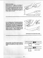
JOtNTING WOOD THAT IS WIDER THAN 3 INCHES
i
:
r,,:., ,./,,,r,,,
•
H k
As:the TRAILING hand passes over the cutterhead,
remove the LEADING hand. :. CONTINUE feedingwhile
placing the:LEADING hand behind:the TRAILING hand.
_ntirlue: feeding in this manner "hand over hand:until
causes a:"rippled, cut:: i ._makesit difficult to guide the
workP!_ _ccuratety anti.could; be hazardous.
JOtNTING WOOD THAT IS THICKER THAN 3 INCHES
_
. Always feed WITH THE GRAIN whenever possible. If .......
:
the nature of :the workpiece iS such that it must be fed
AGAINST THE GRAIN. take very light :cuts and feed
s_owly.
:•
•
i ¸_
•
:
WiTH THE GRAIN
ROTATION
AGAINSTTHE
ROTATION
GRAIN
Support Long Workpieces
To avoid injury from slips or kickbacks, use extra sup_
ports (tables,, sawhorses etc.) at both infeed and outfeed ends if your workpiece is hard to hold down to the
table.
A SAWHORSE OR HOMEMADE
SUPPORT WILL DO
I
I
, i
ii/
ii
J ii1,1 iii
i,ii
iiiiJl.lllmU
I
I I
I
lull IIIII
I
I1'1'111111111111111111111
IIIIIIII1_11
!i
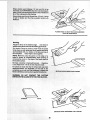
Using the hold-down/push-blocks
ALWAYS use the hold-down/push-blocks when JOINTING wood that is NARROWER than 3 inches or planing
wood that is thinner than 3 inches (as illustrated).
Grasp the hold-down/push-blocks firmly with the fingers
close together and wrapped around the handle_ Position
the hold-down!push-blocks flat on topof workpiece ....
and push the workpiece down againstthe tabieto pro,
.
, .
....
: : .... . .....
vide a qual cut and minimIzethe chance ofa kickback.
.....
::
i'i:
Hold-down pressure must atso :be sufficient to prevent :
hotd-down/push-bock sliding or slipping Onthe top face: of workpiece when advancing workpiece Over cutter
head.
:.........
: ...... _,
::i
Use a hand-over-hand motion of the hold-down/push,
blocks, being careful tOmaintain ControtOver the workpiece at alttimes;
_
:
: :: _ :
This means that once the workpiece has been fed past
the cutter head onto the outfeed table, one hold-down/
push-block must always maintain contact of workpiece
with ouffeed table.:
.....
i:
_....<_-_._--_----__.,_-_._
,
_-...__
_.-...
: ._.i_...__
1 i
t._
JOINTINGWOODNARROWER
THAN3 INCHES
WARNING: iF THE HOLD-DOWN/PUSH-BLOCKS
TEND TO SLIP WHILE FEEDING, CLEAN RUBBER
SURFACE IMMEDIATELY WITH SANDPAPER,
-_,
PLANING WOOD THINNER THAN 3 INCHES
29
lJ
°
:h; Iti,,
greater tenden(
iv
PLANING WOOD 3/4 INCH THICK AND NARROWER
THAN THE PUSH BLOCK
II
'
I
Beveling
Adjust the fence to the desired angle..,
lock fence in
positionusing fence lock knoband sliding guard knob.
pieces of wood 3 inches or wider hold the board
firmly doWn on both tables and firmly against the fence
(asitiustrated) with:your hands on the side and top of
the workpiece ... keep fingers close together:
CHAMFER
BEVEL
BEVELING
......
.........
• ••
30
WOOD NARROWER
THAN 3 INCHES
NOTE::Rabbeting
on a Jointer is considered to be a
dangerous operatioh because it requires removal of the
cutter guard and increases the potential of kickback
because of excessive depth of cut,
NEVER ATTEMPT TO PERFORM A RABBETING OPERATION ON THIS JOINTER. DO NOT OPERATE
JOINTERiPLANER
WITH CUTTERHEAD
GUARD
REMOVED.
Rabbet cuts should be made on the Radial Saw or
Table Saw by making two cuts with the sawblade or by
using the Dado Head or Molding Head. Rabbet cuts
can also be made using the Shaper or Portable Router.
llmllL,
i
RABBETCUT
i.ll_lllll
IIH
.ll II
II.ll
I]
I'lllll
.....,,,,,,,
,
rnaantenance
Do not allow pitch to accumulate on the tables, the
fence, the cutter guard, the cutter head or the knives.
Clean them with Craftsman Gum and Pitch Remover.
If disassembly of the motor is necessary, it should be
returned to your nearest Sears retail or mail order store
in order to prevent voiding the guarantee.
NOTE: The speed of this motor cannot be regulated or
changed.
Apply a thin coat of paste type wax to the tables and
the fence so that the wood slides easily while feeding.
This also deters rusting.
Do not allow chips to accumulate on the underside of
the jointer-planer.
Motors used on wood-working tools are particularly susceptible to the accumulation of sawdust and wood chips
and should be blown out or ,'vacuumed" frequently to
prevent interference with normal motor ventilation.
If power cord is worn Or cut, or damaged in any way,
have it replaced immediately.
iu
.Lllll=i i
H
llll
HHILI
II"IH
I
HIHIll
=
:
....
REPLACING
CUTTER
iiii
!llrllllllli iLJ
ii
i k
IIII
IIII IIII
SLIDING GUARD
KNOB
KNIVESI
WARNING: FOR YOUR oWN:
SAF_
TURN
SWITCH "OFF" AND REMOVE PLUG FROM POWER
SOURCE OUTLET BEFORE ADJUSTING, MAINTAINING, OR LUBRICATING
YOUR i JOINTERPLANER.:
.....
1. Remove the belt guard as follows:
a. Use a screwdriver to loosen both screws, shown
in illustration.
b. Remove sliding guard knob from sliding guard
rod. Turn the knob counterclockwise to unscrew
it from the rod. Raise sliding guard to a vertical
position;
/
c. Slide the belt guard out away from the jointer and
up off the rod,
SLIDING GUARD
31
2-3/4 PAN HD
SCREW
BELT GUARD
U JJ
I
I
I
I
iiiii
i
[111
lJl
i
ii
CUTTERHEAD
5.
cu,erhead pulley
firmly
with or
one
hand and
ii :Hold
lo0seniockscrews!n
each
wedge3
4turnsusing
.
:::-
w oQe
.....
Hex 12:wrench:
ieeVi?
,
i .%._.__.
._LEY
....
.---------
_.-_._..___
.
-----
.
iiii
i]
HLI[
I
I
]1
CUTTERHEAD
PULLEY
EXPECTEDLY. PARTS:MAY LOOSENSUDDENL_ TO
AVOID EYE INJUR_ WEAR SAFETY GOGGLES,
BARS: THEIRHARDENED TIPS CAN SHATTER UNhand,_gent_y pry up each Wedge using a small pry
bar. Remove wedges andknives. :
:
knives is as foliows: :
....
a. Locate the two lifter screws under the knife.
b. Hold the cutterhead pulley firmly with one hand
to prevent ,the cutter head from turning.
c. Using a i18 Hex-L wrenchl turn one of the lifter
screws 1/4 of a turn counterclockwise.
d. Now turn the other lifter screw 1/4 of a turn
_.€ontinuetUrning first one lifter screw and then
turn at a time until the knife
-
counterclockwise.
remove the knives using
oil soak in be-
.....
"
..,,
.......
5/32 IN. SETSCREW
WRENCH _'_
LIFTER
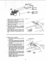
7. Using a 1/8" Hex "t.'.'wrench, remove the six lifter
screws, (Two under each blade.)
8, Clean cutterhead, wedges and screws thoroughly
with Craftsman Gum and Pitch Remover. Also remove the oil from new blades.
9. Replace the six lifter screws and screw them in all
the way, but do not tighten,
10. Insert a knife in one of the slots,.,
so it projects
1/t6 of an inch beyond each end of the cutterhead.
Note that the face with the cutting edge is against
the wedge as shown,
11. Insert a wedge next to knife so the flat side of the
wedge is against the knife. Push wedge in manually-do not install two locking setscrews at this
time.
• _i<_:ii_!!_, _ :i,i, _!,i_i,_i,_i/_ ii ii_i !_
12. Adjust cutter knives as follows::
:
a. Put a piece of notebook paper on top of the
NOTEBOOK
outfeed table.
:_
....... __
PAPER
b. Put the head of a squareon topof the paper.
The end of the square must extend past the end
of the outfeed table and above one end of the
cutterhead;
i ,
i....
c, Turn the lifter screws counterclockwise to raise
the knife until if just touches the square.
d, _To check your adjustrnenti I;gently turn the cutterhead back and forth by moving the cutterhead
pulley, The knife should just touch the square
without raisinglthe square off the paper. This
same adjustment must be made at the other
end of the cutterhead.
e. tfthe adjustment:is done correctly, the knives
will nowbe slightly above the ouffeed table by
approximately :003 of an inch (the thickness of
an, average piece of paper),
.... NOTE: This adjustment can be made more accurately by:using a knife setting gauge (Cat,
#9-2647) available at Sears.
i
¸
OUTFEED
TABLE
•
33
N(_ irtsta!! bothlockingsetscrewsandtighten(with
tt_e5/32_'Hex:L Wrench)alternately a little:at a:time.
.....ttoigi_tenboth:
securely.;
::"i:
make sure Screws
it didonot
change Recheck:the
_sitioni::
: blade
::i
-!4:1=l_stai! the other: twokiiiveS
_ i5: Ret_stail the belt guaid,; sliding guard, and slid ng
....
guard knob.
::.
:
CAUTION=THE CUTTER KNIVES ARE VERY SHARR
TO PREVENT A SLIP OF THE HAND WHICH COULD
CAUSE CUTTING OF YOUR HAND, ALWAYS HOLD
ONTO THE CUTTERHEAD PULLEY TO PREVENT
ACCIDENTAL ROTATION OF THE CUTTERHEAD.
SHARPENING
CUTTER
_
__
KNIVES
The knives can be honed individually with an ordinary
oilstone,
Make sure your oilstone is not worn in the center. It
must be flat.
Besure to remove the burr on the flat side.
11/16
IN.
NEW BLADE
if the knives are nicked, they must be replaced or reground:: They can be regrounded several times until
they become 9/16 in. wide: Never install reground
knives
less than 9/16 in, wide 0r unbalanced knives_
.
ave your knives reground by s0m_0newho:iscompetent. I_ooki_: the Yellow Pages 'of your:telephonedirec_
tory :i .:;:!See::,SharpeningService's."
..........
_=
-
34
5
RAISE the end of the FENCE, rotate the guard
COUNTER clockwise onIy enough to CLEAR fence
6. LOWER the fence and tighten
both knobs
The normal position of the guard (at REST) when the
fence is stationed at MAXIMUM WIDTH OF CUT, is
shown as position
"A" NEVER
ROTATE GUARD
BEYOND
POSITION
"B" BECAUSE
THIS WOULD
EXERT EXCESSIVE TENSION ON SPRING WHICH
COULD WEAKEN OR BREAK IT
Check operation
of GUARD
POSITION
"A _'
and SPRING
1 With fence in MAXIMUM WIDTH OF CUT position,
pass a piece of 1/4 in thick wood on edge (jointing
position) over cutterhead
2
The guard should return automatically
to its REST
position against the fence when free of the wood
3. If guard does not return to its REST position, remove
the guard by following steps 1 thru 6 above Make
sure the spring is installed correctly and not broken
If the spring is broken it must be replaced
Reassemble the guard and spring
following steps 1 and 2
and test again by
If guard still does not return to its REST position, consult
your local Sears Retail Store before using the jointer
planer
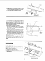
lubrication
The BALL BEARINGS in this machine are packed with
grease at the factory. They require no further lubrication
The following parts should be oiled occasionally
SAE No 20 or No 30 engine oil
1 Dovetail
spacer and dovetail
"with
slide
2, Elevating screw (first clean with Craftsman
Pitch Remover).
\
\\
Gum and
DOVETAIL
SPACER
AND
SLIDE
ELEVATING
35
SCREW
VIEW LOOKING
UP FOR
PARTS fDENTIF1CAT!ON
i:Motorwtiinot _ni: ::i: :i
::i;_:Defective onLoff Switchl;:II '
ii;::;_::
::
::::
:: :!:::i : i: :.Def_ive relay.::
:::i _: i i:
;
;:: _:
Defectivecapabitor,
i
i;::
!:_:::i
:
:i
Defectiv_ motor::: '::
:
:
::
: :_Low line voltagel
:; :
• i :,_ ':.:
i :......
t : Belt tension too high, :
ConSult sears Serv c'ei'Any attempt i 'o'repa r th s e ecirical
dev ce may createa HAZARD unless repair is dode by a
qua fiedserv cetechnic an Repa rserv ce is ava able
at your nearest Sears store
Adjust belt tension.
:Wood strikes outfeed
,table after passtng over
€uu_head_
Blades improperlyadjusted
'""'
Re-adjust b ades see Ma ntenance section.
: belowsurfaCe Ofouffeed table.
I _
:
:
i
i 1
R|ppii_$ on planed
: surface. I
i:
:
Kickl_cks.
: ......
:i ..... i
_, :
.....
:
other:
;
;
:i: 2;i Feedingwoodtoo fast.
I 3. Cutting knives am settoo h gh
I _aboVe ouffeed table ortheyare
not leveled with outfeed table.
1. Re-adjustblades
seeManienancesecton.
2. Feed wood slower.
3. Re-adjustbades
see Ma ntenance sect on
:
i
lnfeed tab e out of adjustment
Re-adjust infeed table, see Gett ngTo Know Your Jointed
P aner section:
:
,:l,...........
5/16"-181ockbotloose.
11 Tighten Iockbolts
....
|
Cutter gtiard does not ,
furllctiorl:properly.
:
: :
::
:: :i=:;
:: :: :
: t. Return spdng broken;:or:
...... i spr ng has bt_en Weakenedl
: _::
:
_
_
_
:::i
_ :
:;ii;i_i
:
_i_: i
:ii_:i;i'i!!i;:i!i
'_:::::': :i;:i_:_ii:::i,;::i
:i
WHITE
:
_,_....
C0nsult Sears Serv{Ce immediately, Any attempt to repair
: th sguard maycreate a hazard un ess repair is done by a
qua lfied servlcetechntclan. Repair service ts available at
atyournearestSebrsstore_
WHITE
_
WIRE
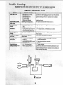
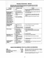
TROUBLE
SHOOTING--
MOTOR
NOTE: Motors used on wood.working tools are particularly susceptible tothe accumulation
of sawdust and wood chips and sho_Jid be blown Out or"vacuumed" frequently to prevent
interference with normal motor ventilation.
PROBABLE
CAUSE
TROUBLE
Excessive noise.
..........
REMEDY
I
1. Motor.
1. Have motor checked by qualified service technician.
Repair service isavailable at your nearest Sears store.
2. Tighten setscrew, ........
2. Pulley setscrew loose,
Motor fails to develop
full power. NOTE:
LOWVOLTAGE: (Power
outputof motor
decreases rapidlywith
decrease in voltage at
motor terminals. For
example, a reductionof
10% involtage causes a
reductionof 19% in
maximum poweroutput
ofwhich the motor is
capable, anda reduction
of20% in voltage causes
a reductionof 36% in
maximum power output.)
t. Circuit overloaded with
lights,appliances and other
motors,
2, Undersize wires or circuit
too long,
Motor starts slowly
or fails to come up
to fullspeed.
1,
Request voltage check from the power company.
1. Low voltage will not trip
relay.
2. Have motor repaired or replace&
2. Windings burned outor
open.
3. Have re_ay replaced,
3. Starting relay notoperating.
4. Drive belt tension..to.0..h.!gh. . 4. Adjust belt tension.
Motor overheats.
1, Motor overloaded.
2. Impropercooling. (Air
circulationrestricted
through motordue to
sawdust accumulating
inside of motor.)
3. Defective
relay.
:
=
:
Motor stalls (resulting
in blown fusesor
: :
trippedcircuit breakers,)
2. Increase wire sizes, or reduce length of wiring. See
"Motor Specificationsand Electrical Requirements"
section.
3. Request a voltage check from the power company.
3. General overloadingof
power company facilities.
1. Feed work slower into blade.
2. Clean out sawdust to provide normal air circulation
through motor. See !'Maintenance and Lubrication"
section.
I
....
2. Voltage too;lowto permit:
motor to reach operating
3. Fuses0rcircuitbreakers
_
: :do not have sufficient .....
:capacity.
Frequent opening of
fuses or circuit
breakers,
1. Do not use other appliances or motors on same circuit
when using the jointer.
i :i
:.
2. Request voltage check from the power company.
'
3; Installpropersizefusesorcircuitbreakers.Seeelectdcal
connection section.
:.... .......... ...........................................
1, Motoroverloaded. _
2. Fuses orcircuit breakers
do not have sufficient
,capacity.
SEARS RECOMMENDS
ITEM
Cutter Blades .,..
:.,.
.................
Power Tool Know-how Handbook:
.........
Knife Setting Gauge ,.. ;
............
Chip Collector.._.
....
: ........
. ......
3.: Have relay replaced,
t......
, 'i, Feed work slower.
i 2. Install proper size fuses or circuit breakers. See electrical
connection section.
THE FOLLOWING
CAT. NO.
9-2293
9-29117
:. 9-2647
9-29974
ACCESSORIES
Sears may recommend other accessories not listed in
the manual. See your nearest Sears store or Catalog
department for other accessories.
Do not use any accessory unless you have received
and read complete instructions for its use.
37
i_ :i _iz_ :
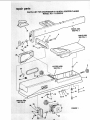
LIST FOR CRAFTSMAN 6,1/8-INCH
MODEL NO;1113;232210
34
JOINTER-PLANER
FENCE ASM.
SEE FIG. 2
_
TABLE ASM.
SEE FIG, 3
/
31
32
•
+
5
/
SEE FIG. 4
• ui:
-u
_/: :,
_+
9
:_ _
:•i••:•; ••
_t
10
12
15 14 13
:_;ii:::/¸¸
1+
• •:':
FIGURE 1
i i :
,ii
parts
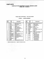
PARTS
LIST FOR CRAFTSMAN 6-1/8,.INCH
MODEL NO:113.232210
JOINTER-PLANER
Always order by Part Number -- Not by Key Number
FIGURE 1 - JOINTER ASSEMBLY
*
Key
No.
Part
No.
t
2
3
4
5
6
7
8
9
10
11
12
13
14
15
16
17
18
19
2O
2t
21237
2t 738
STD533725
18437
818099
820081
102832
STD541031
18516
STD551131
STD523117
67017
STD551025
STD551225
STD522505
STD551210
STD511103
63418
STD328022
820074
60025
Description
Bracket Fence Slide
Retainer Bolt
* Bolt-Crg 3/8-16 x 2-1/2
Washer
Knob Elevation
Base-Jointer/Planer
Screw-SL Set 5/16-18 x 1
* Nut-Hex 5/16-18
Stud-Leveling
* Lockwasher-5/16
* Screw-Hex 5/16-18 x 1-3/4
Spacer
* Washer-17/64 x 3/4 x 7/64
* Lockwasher-1/4
* Screw-hex Hd 1/4_20 x1/2
* Lockwasher-Ext t0 .....
*Screw-Pan Hd 10-32x 3/8 :'
Clamp-Cord ....
:
*Pulley
" ....
,....
Motor
Screw-Hex ad 5/16-18 x 3t4
•
Key
No.
Part
No.
Description
22
23
24
25
26
27
28
29
30
31
32
33
34
--
STD551031
818098
806196-3
8! 6573
STD328012
STD304210
818100
808277-1
62331
47624
STD551037
132.275
: 67062
508091
*Washer-21/64 x 5/8 x 1/16
Support-Motor
Grommet-Rubber
Cord w/Plug
*Pulley
*Beit-V4L21 inch
Guard-Belt
Screw-Pan Hd 10-32 x 2-3/4
Knob-Lock
Spacer
* Washer-.380 x 19/64 x 7/64
Screw-Fil Hd 1/4-20 x 1
Block-Push
Bag of Loose Parts
(Not Illustrated)
Bag of Loose Parts
(Not Illustrated)
Bag of Loose Parts
(Not Illustrated)
Owners, Manual
(Not Illustrated)
i ¸
i
508093
508210
SP5447
Standard Hardware item -- May Be Purchased Locally.
i
39
2
3
4
10
15
Always orderby
Part !Number-"
FIGURE2
[ Key _i
_NO,
"
Part
......
_ No.
"|
.1
III J!
• Description
i
"FENCE
:
.
Not byKey
Number
ASSEMBLY
Key
No.
Part
No,
11
STD55!010
12
13
!4
15
16
17
STD510802
STD551150
STD541050
818104
21622
.67020
i
I
67OO9
STD51 i102
Description
Guard-Cutter
:
* Screw-Pan Hd 10-32 x 1/4
:i:i!i:5::!,
i:••_•: .
40::•••.
l,
*Washer
t3/64 x 1/2 x 3/64
* Screw-Bind Hd 8-32 x 1/4
* Lockwasher-1i2
*Nut-Hex Jam 1/2-13
Rod-Sliding Guide
Washer-Sliding Guard
Knob-Sliding Guard
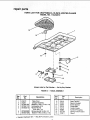
repair parts
PARTS LIST FOR CRAFTSMAN 6-1/8-iNCH
MODEL NO. 113.232210
JOINTER-PLANER
Atways order by Part Number -- Not by Key Number
IFIGURE 3 -- TABLE ASSEMBLY
Key
No,
Part
No.
IKey
Description
No,
Part
No.
'111'
1
2
3
4
5
818101
21204
STD55!031
STD551131
STD523112
STD522505
7 _ STD551025
*
Table-Front
Linkage-Assembly
*Washer-11/32x 11/16x t/16
* Lockwasher-5/16
* Screw-Hex Hd
5/16-18x 1-1/4
*Screw-Hex Hd !/4-20 x t/2
Washer-17/64 x 47/64 x 1/16
10
11
12
13
14
Standard Hardware Item -- May Be Purchased Locally.
41
21812
21422
21635
21219
21218
60388
817734
816871
Description
I
Plate-Tension
Spacer-Dovetail
Screw-Special
Guide*Male
Guide-Female
Nut-Self Threading
Spring-Torsion Guard
Guard
•/:<
ii_:_i
_
=_
i_i::/i_
_
:i¸: _i: i-¸
1
/
2
3
4
3
/
/
5
/
?
7
Aiwaysorderby
Part Number _-Not
by Key Number
FIGURE 4 -- CUTTER ASSEMBLY
Key •
No.
Part
No.
Description
i
¸¸¸¸i¸1
¸
':_3:
Stock Item --May _:S_cure,
8
9
!0
! 11
_, !2
21450
21632
9-2293
60116
60118
I
Head Asm.-Complete Cutter
Wedge
I"Blade
Screw-Soc Cap 10-32 x 3/4
Screw Ftat Hd Soc
10-32x !/2
; Retail or Catalog Order Houses.
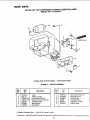
repair parts
PARTS LiST FOR CRAFTSMAN 6-1IS-INCH JOINTER-PLANER
MODEL NO. 113.232210:
13
11
1
7
Always order by Part Number -- Not by Key Number
FIGURE 5 -- SWITCH ASSEMBLY
Key ...................
Part
No.
No.
Description
i_
:i:
Pan
No.
Key
No.
1
1
2
3
4
5
6
7
816924-1
Lead
816t 13
Switch,Locking:
STD551210
* Lockwasher-Ext #10
STD51 t103
*Screw-Pan Hd 10-32 x 3/8
8037091
: Connector-Wire
816880
i Bezel-Switch
9-22256
i t Key-Switch
.......
8
9
10
11
12
13
816274-2
817399-6
816560-1
816881
820075
816560-2
Description
i•
i
Screw-Pan Hd #10 x 1
Relay Model !01
Lead-Jumper
Housing-Switch
Capacitor-Dry Film
Lead-Jumper
i i....................
* Standard Hardware Item "
May Be Purchased Locally.
1- Stock Item -- May Be Secured Through The Hardware Department Of Most Sears Retai} or Catalog Order Houses.
43
JOINTER.PLANER
....,: ::
1
\
7
Always order by Part Number--Not
by Key Number
FIGURE 6 -- LEG SET ASSEMBLY
Key
No.
ii
Part
No.
,
,
7
8169O8
8
805589-5
9
STD551225
10
STD541025
--50771
!
Description
i
Stiffener-Lower
Screw-Truss Hd 1/4-20x 1/2
,Lockwasher-Ext. 1/4
, Nut-Hex 1/4-20
Bag of Loose Parts
(Not Illustrated)
NOTES
45
i'
i!
6-I/8
JOIHr RoPLANER
SERVICE
MODEL NO.
113.232210
Now that you have purchased
your jointer-planer,
need ever exist for repair parts or service, simply
any Sears Service Center and most Sears, Roebuck
stores. Be sure to provide all pertinent facts when
or visit.
should a
contact
and Co.
you call
The model number of your 6-I/8 inch jointer-planer
found on a plate attached to the base.
will be
JOINTER/PLANER WITH
LEGS AND MOTOR
HOW TO ORDER
REPAIRPARTS
WHEN ORDERING REPAIR PARTS,ALWAYSGIVE THE FOLLOVvlNG
INFORMATION:
PARTNUMBER
PARTDESCRIPTION
MODEL NUMBER i
113.232210
NAME OF ITEM
6-I/8 INCH JOINTER-PLANER
Allpartslistedmay be ordered from any Sears Service Center
and most Sears stores.Ifthe partsyou need are not stocked
locally,
your order will
be e|ectronica|ly
transmittedto a Sears
Repair PartsDistribution
Center forhandling.
J
Form
No. SP5447
PrintedinTaiwan 8/90