1
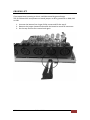
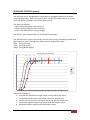
USER’S MANUAL
Rev. 2015-03-17
GKPX-14
GK Parallel Box
1
Table of Contents
INTRODUCTION ......................................................................................................................... 3
13-PIN CONNECTORS................................................................................................................. 3
THE FOUR LED’s (Light Emitting Diodes) ................................................................................... 4
UNDERSTANDING THE GK VOL CONCEPT ................................................................................. 4
FOOTSWITCH AND STOMP PROGRAM P1, P2 and P3 ............................................................... 5
STOMP PROGRAM P1 ............................................................................................................ 6
STOMP PROGRAM P2 ............................................................................................................ 7
STOMP PROGRAM P3 ............................................................................................................ 8
SETUP WIZARD .......................................................................................................................... 9
STEP 1. Setting the GKVOL operating mode, MUTE or MAXVOL .......................................... 9
STEP 2. Setting the number of connected synth units. ......................................................... 9
STEP 3. Selecting the Stomp Pattern Program 1, 2 or 3 ...................................................... 10
GROUND LIFT........................................................................................................................... 11
SUBSONIC FILTER (option) ....................................................................................................... 12
GKPX-14
GK Parallel Box
2
GKPX-14 GK Parallel Box
INTRODUCTION
The GKMX-14 stomp box allows you to connected to up to four 13-pin Guitar
Synthesizer units such as Roland GR-33, GR-55, VG-99, Boss GP-10 or other similar
13-pin devices.
The 13-pin input is compatible with Roland GC-1 or any other 13-pin GK-3, GK-2 or
GK-KIT equipped guitar.
There’s only one footswitch to control the behavior of this small box.
NOTE: It is important for you to read this document in full to grasp all the available
features. It is also important that you run the Setup Wizard (see separate chapter)
to setup the box to suit your needs.
13-PIN CONNECTORS
The 13-pin connectors are soldered to the printed circuit board. Please do not use
more force or violence than required.
Connect the Guitar to the connector marked “IN” and a Guitar Synth to the output
marked “GK A”. Do not turn on power until all connections are made.
NOTE: THE SYNTH CONNECTED TO “GK A” IS POWERING THE BOX.
THE BOX WILL NOT OPERATE UNTIL THE SYNTH CONNECTED TO “GK A”
IS TURNED ON.
GKPX-14
GK Parallel Box
3
THE FOUR LED’s (Light Emitting Diodes)
Each unit output (GKA, GKB, GKC and GKD) has a two-colored LED. The colors are
RED and GREEN.
If both LED’s are activated, the color will show YELLOW.
GREEN
ON
- The guitar GK VOL knob level is directed to the synth.
OFF - A fixed voltage is directed to the synth, either MUTE or MAXVOL
(explained elsewhere)
RED
ON
OFF
- The guitar S1 and S2 buttons are directed to the synth.
- The synth will NOT react when pressing the S1/S2 buttons.
YELLOW
ON
- Both guitar GK VOL knob level is directed to the synth as well as the guitar
S1/S2 buttons.
UNDERSTANDING THE GK VOL CONCEPT
Most people use the Guitar GKVOL knob to control the output volume of the synth.
GKVOL is one of the wires in the 13-pin cable.
The voltage on this wire may affect various parameters in the synth unit, but as said,
in many cases it affects the Patch Volume. This can easily be modified in the patch
setting of the synth.
The GKPX-14 allows you to individually connect the GKVOL signal to any or several of
the connected synth units.
When this VOL connection is enabled, (indicated by the GREEN component of the
LED) the guitar GK VOL knob modifies the volume/expression of the synth(s).
However, if this VOL connection is disconnected (GREEN component of LED is OFF) ,
there can be two optional voltages feed to the synth. Either full volume (+5V) or
silence (0V)
“MUTE” corresponds to the functionality of a Roland US-20 unit (0V).
“MAXVOL” corresponds to the functionality of a Roland GKP-4 unit (+5V).
NOTE: THIS SETTING IS PROGRAMMABLE USING THE SETUP WIZARD.
FACTORY DEFAULT IS “MUTE”
GKPX-14
GK Parallel Box
4
FOOTSWITCH AND STOMP PROGRAM P1, P2 and P3
The Footswitch will operate a wide range of stomp patterns. Depending on how you
prefer to use the unit there are three different programs: P1, P2 and P3.
P1 – (Factory default), this program is easy to understand and might be a good
starting point. For use at home or in a studio this might be the preferred program.
P2 – When playing guitar in a live situation a single-stomp or a double-stomp may be
the most multi-tasking effort you can afford without affecting your playing. For live
use and with many connected synth units, P2 might be the most effective program
to limit tap-dancing. However P2 may require training to comprehend.
P3 – This program is also easy to understand and allows operation similar to a US-20
unit selector. IF YOU HAVE ONLY TWO SYNTHS THIS PROGRAM MAY BE YOUR
FAVOURITE
We strongly suggest you try all programs to see which one you handle the best.
NOTE: TO SELECT BETWEEN P1, P2 or P3 YOU MUST RUN THE SETUP WIZARD.
GKPX-14
GK Parallel Box
5
STOMP PROGRAM P1
This program allows direct access to each unit just by stomping the number of the
output. If the ending stomp is longer than 1.5 seconds it has a different meaning.
Description of the “Morse code”:
Dot “.”, represents a stomp where the footswitch is held down <1.5 seconds.
Dash “-“, represents a stomp where the footswitch is held down >1.5 seconds
(command executes automatically after 1.5 sec without releasing the footswitch).
If you have configured for 2 synths using the Setup Wizard:
Stomp pattern
Morse code
Action
Single-stomp
.
Toggle unit A VOL mode
Double-stomp
..
Toggle unit B VOL mode
Triple-stomp
...
Toggle VOL mode on ALL
Single-stomp-long
Double-stomp-long
Triple-stomp-long
...-
Change unit A S1/S2 mode
Change unit B S1/S2 mode
Toggle S1/S2 mode on ALL
If you have configured for 3 synths using the Setup Wizard:
Stomp pattern
Morse code
Action
Single-stomp
.
Toggle unit A VOL mode
Double-stomp
..
Toggle unit B VOL mode
Triple-stomp
...
Toggle unit C VOL mode
Quad-stomp
....
Toggle VOL mode on ALL
Single-stomp-long
Double-stomp-long
Triple-stomp-long
Quad-stomp-long
......-
Change unit A S1/S2 mode
Change unit B S1/S2 mode
Change unit C S1/S2 mode
Toggle S1/S2 mode on ALL
If you have configured for 4 synths using the Setup Wizard:
Stomp pattern
Morse code
Action
Single-stomp
.
Toggle unit A VOL mode
Double-stomp
..
Toggle unit B VOL mode
Triple-stomp
...
Toggle unit C VOL mode
Quad-stomp
....
Toggle unit D VOL mode
Penta-stomp
.....
Toggle VOL mode on ALL
Single-stomp-long
Double-stomp-long
Triple-stomp-long
Quad-stomp-long
Penta-stomp-long
GKPX-14
..........-
Change unit A S1/S2 mode
Change unit B S1/S2 mode
Change unit C S1/S2 mode
Change unit D S1/S2 mode
Toggle S1/S2 mode on ALL
GK Parallel Box
6
STOMP PROGRAM P2
This program uses a cursor (flashing LED) to highlight a unit for further action. At a
certain point in time you apply a change to the unit.
The cursor is indicated by a flashing of the LED. If any of the LED-components are ON
the cursor will DIM the led periodically but having it mostly ON.
If both of the led-components are OFF the cursor will LIGHT the LED periodically but
having it mostly OFF.
Moving the cursors does not affect any other setting such as GK VOL or S1/S2
control.
Description of the “Morse code”:
Dot “.”, represents a stomp where the footswitch is held down <1.5 seconds.
Dash “-“, represents a stomp where the footswitch is held down >1.5 seconds
(command executes automatically after 1.5 sec without releasing the footswitch).
Stomp pattern
Single-stomp-long
Single-stomp
Double-stomp
Double-stomp-long
Morse code
.
..
.-
Action
Toggle VOL mode on ALL
Toggle selected unit VOL mode
Move cursor to the next unit
Move cursor to previous unit
Triple-stomp
...
Quad-stomp
....
Make selected unit exclusive for VOL and
S1/S2
Toggle selected unit S1/S2 mode
GKPX-14
GK Parallel Box
7
STOMP PROGRAM P3
This program allows direct toggling between the units similar to a US-20 unit.
Description of the “Morse code”:
Dot “.”, represents a stomp where the footswitch is held down <1.5 seconds.
Dash “-“, represents a stomp where the footswitch is held down >1.5 seconds
(command executes automatically after 1.5 sec without releasing the footswitch).
If you have configured for 2 synths using the Setup Wizard:
Stomp pattern
Morse code
Action
Single-stomp
.
Toggles A or B on VOL and S1&S2
Double-stomp
..
Enables VOL mode on BOTH
If you have configured for 3 synths using the Setup Wizard:
Stomp pattern
Morse code
Action
Single-stomp
.
Cycle A->B->C on VOL and S1&S2
Double-stomp
..
Enables VOL mode on all THREE
Single-stomp-long
Reverse cycle C->B->A on VOL and S1&S2
Triple-stomp
...
Activate selected + 1
Quad-stomp
....
Activate selected + 2
Single-stomp-long
Double-stomp-long
Triple-stomp-long
...-
Cycle C->B->A on VOL and S1&S2
Activate selected - 1
Activate selected - 2
If you have configured for 4 synths using the Setup Wizard:
Stomp pattern
Morse code
Action
Single-stomp
.
Cycle A->B->C->D on VOL and S1&S2
Double-stomp
..
Enables VOL mode on all FOUR
Single-stomp-long
Reverse cycle D->C->B->A on VOL and S1&S2
Triple-stomp
...
Activate selected + 1
Quad-stomp
....
Activate selected + 2
Single-stomp-long
Double-stomp-long
Triple-stomp-long
Quad-stomp-long
GKPX-14
......-
Cycle C->B->A on VOL and S1&S2
Activate selected - 1
Activate selected - 2
Activate selected - 3
GK Parallel Box
8
SETUP WIZARD
The Setup Wizard allows you to customize your GKPX-14.
NOTE: TO INVOKE THIS MODE, HOLD DOWN THE FOOTSWITCH MORE THAN 8
SECONDS UNTIL ALL LEDS’S STARTS FLASHING SIMULTANOUSLY. THEN RELEASE
THE FOOTSWITCH.
The Setup Wizard allows you to:
1. Decide if you want to be able to MUTE the sound (similar to a Roland US-20
device) or to be use MAX VOLUME (similar to a Roland GKP-4 device)
2. Inform the GKPX-14 how many synth units you plan to connect.
3. Selecting stomp pattern programs P1 or P2
STEP 1. Setting the GKVOL operating mode, MUTE or MAXVOL
In this the first step all four LED’s are flashing GREEN or RED.
Each single-stomp toggle between these two modes:
GREEN - Select this mode if you want to be able to MUTE (*) your synths
(Roland US-20 mode)
RED
- Select this mode if you want to use MAXVOL(*) on unselected synth units
(Roland GKP-4 mode)
(*) Note: To MUTE or put the synth to MAX VOLUME, the GKVOL control must be
assigned to Patch Volume in each of the synth units. See the user’s guide of the
particular synth unit.
Double-stomp to store the setting and continue with Step 2.
STEP 2. Setting the number of connected synth units.
In this step the number of LED’s flashing YELLOW indicates the number of synth units
you are planning to use.
Press the footswitch to change the number of flashing YELLOW LED’s (1->2->3->4>1->2 … etc.) until the proper number is shown.
Double-stomp to store the setting and continue with Step 3.
GKPX-14
GK Parallel Box
9
STEP 3. Selecting the Stomp Pattern Program 1, 2 or 3
In this step one, two or three LED’s will flash GREEN.
- Select one flashing LED for P1
- Select two flashing LED’s for P2
- Select three flashing LED’s for P3
See other chapter for describing the stomp pattern programs.
Please try out all programs and use the one that works best for your need and taste.
Complete this step with a Double-stomp and exit the Setup Wizard procedure.
NOTE: WHEN SETUP IS FINALIZED YOUR SETTINGS WILL BE PERMANENTLY STORED
IN FLASH MEMORY UNTIL YOU RUN THE WIZARD AGAIN.
GKPX-14
GK Parallel Box
10
GROUND LIFT
If you experience humming or hiss it could be caused by ground loops.
The PX-14 board V3 incorporates on-board jumpers to do a ground lift on GKB, GKC
or GKD
1. Unscrew the bottom four larger Phillip screws and lift the top of.
2. Remove the jumper located underneath the board at actual GK connector.
3. Put the top and the four screws back again.
GKPX-14
GK Parallel Box
11
SUBSONIC FILTER (option)
The GKPX-14 can be equipped with a permanently engaged Subsonic Filter Board
(ordered separately). Note: This board is NOT suitable for Electric Bass or if you detune your guitar to below C2 on the thickest E-string.
The filter will improve:
- PCM Tracking and ghost note immunity
- COSM Tracking and ghost note immunity
- Lower noise when Palm muting at bridge
The effect is most noted on GR-55, VG-99 with Piezo guitars.
The Subsonic Filter consists of six filters (one for each string), eliminating rumble and
low frequency noise. The High-Pass filters remove frequencies below:
50Hz (string E and A),
75Hz (string D and G)
100Hz (string B and High E)
Masured Subsonic Filter Characteristics
1,2
C2 D2 E2
G2 A2
C3 D3
F3
G3
A3
B3
1,1
1
0,9
0,8
STR1 - High E
STR2 (H)
0,7
STR3 (G)
STR4 (D)
0,6
STR5 (A)
STR6 (Low E)
0,5
0,4
0,3
0,2
0,1
0
0
50
100
150
200
250
300
350
400
Installation procedure:
4. Unscrew the bottom four larger Phillip screws and lift the top of.
5. Locate and remove the six red jumpers from the jumper pins.
6. Carefully fit the board so the female connector fits the jumper pins.
7. Fit the two supplied supporting nuts to hold the board in place.
8. Assemble the box and put back the Phillips screws.
GKPX-14
GK Parallel Box
12
UNINSTALLING THE FILTER BOARD
1. Unscrew the four bottom larger Phillip screws and lift the top of.
2. Unscrew the two Phillips screw holding the filter board.
3. Remove to board by wiggling it upwards.
4. Underneath the board you should find a plastic bag containing 6 small 2mm
jumpers (if not, please contact Primova).
5. Place the six (6) jumpers (one for each string) at the top positions of
connectors.
6. Put the top cover back and the screw the four large Phillips screws back in
place.
GKPX-14
GK Parallel Box
13
WARRANTY
PRIMOVA AB WARRANTS THE GKPX PRODUCT FOR ONE YEAR. TWO YEARS IF INSIDE
EU.
LIMITATION OF LIABILITY AND WARRANTY
NO WARRANTIES OF DAMAGES TO CONNECTED EQUIPMENT OR CABLES.
NO WARRANTIES IF UNSUITABLE VOLTAGE HAS BEEN APPLIED TO CONNECTORS.
PRIMOVA AB ONLY WARRANTS THE GKPX UNIT ITSELF.
CONNECTING THE GKPX UNIT OR THE GKPX BOARD, TO OTHER COMPONENTS SUCH
AS GUITARS OR SYNTHESIZERS IS AT OWN RISK.
IN NO EVENT WILL PRIMOVA BE LIABLE FOR DIRECT, INDIRECT, SPECIAL,
INCIDENTAL, OR CONSEQUENTIAL DAMAGES ARISING OUT OF THE USE OR THE
INABILITY TO USE THE GKPX-UNIT EVEN IF ADVISED OF THE POSSIBILITY OF SUCH
DAMAGES. IN PARTICULAR, PRIMOVA IS NOT RESPONSIBLE FOR ANY COSTS
INCLUDING BUT NOT LIMITED TO THOSE INCURRED AS A RESULT OF LOST PROFITS
OR REVENUE, LOSS OF USE OF THE GKPX PRODUCT, LOSS OF DATA, THE COST OF
SUBSTITUTING THE GKPX-UNIT, OR ANY CLAIMS BY THIRD PARTIES.
© Copyright Primova AB Sweden 2014
PRIMOVA AB
Kurlandaallén 21
68151 Kristinehamn
Sweden
www.primovasound.com
[email protected]
GKPX-14
GK Parallel Box
14
GKPX-14
GK Parallel Box
15