1
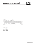
Owner’s Manual
X-Series
™
Rack Mount Mixers
X 18R™ / X 20R™
Important Precautions
1
Save the carton and packing materials! Should you ever need to ship the unit,
use only the original factory packing.
For replacement packaging, call Crest Audio’s
Customer Service Department directly.
2
3
Read all documentation before
operating your equipment. Retain all
documentation for future reference.
Follow all instructions printed on
unit chassis for proper operation.
Service Information
Do not open unit!
Opening the unit will expose you to potentially dangerous voltages. There are no user
serviceable parts inside.
Equipment should be serviced by
qualified service personnel when:
A. The equipment has been exposed to rain.
B. The equipment does not appear to operate
normally, or exhibits a marked change in
performance.
C. The equipment has been dropped, or the
enclosure damaged.
4
5
Do not use the unit if the electrical
power cord is frayed or broken.
The power supply cord should be routed so
that it is not likely to be walked on or pinched
by items placed upon or against it.
Always operate the unit with the
AC ground wire connected to the
electrical system ground. Precautions
should be taken so that the means of
grounding of a piece of equipment is not
defeated.
6
Damage caused by connection to
improper AC voltage is not covered by any warranty.
7
Do not spill water or other liquids
into or on the unit, or operate the
unit while standing in liquid.
8
The power cord of equipment
should be unplugged from the outlet when left unused for a long
period of time.
To obtain service:
contact your nearest Crest Audio Service
Center, Distributor, Dealer,
or Crest Audio at
Phone: 866-812-7378 USA
or visit www.crestaudio.com for additional
information.
email
[email protected]
X 18R / X 20R Owner’s Manual
This symbol is used to alert
the operator to follow important
procedures and precautions
detailed in documentation.
This symbol is used to warn operators that uninsulated “dangerous
voltages” are present within the
equipment enclosure that may
pose a risk of electrical shock.
Intended to alert the user to the presence of uninsulated “dangerous voltage” within the product’s
enclosure that may be of sufficient magnitude to constitute a risk of electric shock to persons.
Intended to alert the user of the presence of important operating and maintenance (servicing)
instructions in the literature accompanying the product.
CAUTION: Risk of electrical shock — DO NOT OPEN!
CAUTION: To reduce the risk of electric shock, do not remove cover. No user serviceable parts
inside. Refer servicing to qualified service personnel.
WARNING: To prevent electrical shock or fire hazard, this apparatus should not be exposed
to rain or moisture‚ and objects filled with liquids‚ such as vases‚ should not be placed on
this apparatus. Before using this apparatus‚ read the operating guide for further warnings.
Este símbolo tiene el propósito, de alertar al usuario de la presencia de “(voltaje) peligroso” sin
aislamiento dentro de la caja del producto y que puede tener una magnitud suficiente como para
constituir riesgo de descarga eléctrica.
Este símbolo tiene el propósito de alertar al usario de la presencia de instruccones importantes
sobre la operación y mantenimiento en la información que viene con el producto.
PRECAUCION: Riesgo de descarga eléctrica ¡NO ABRIR!
PRECAUCION: Para disminuír el riesgo de descarga eléctrica, no abra la cubierta. No hay piezas
útiles dentro. Deje todo mantenimiento en manos del personal técnico cualificado.
ADVERTENCIA: Para prevenir choque electrico o riesgo de incendios, este aparato no se
debe exponer a la lluvia o a la humedad. Los objetos llenos de liquidos, como los floreros,
no se deben colocar encima de este aparato. Antes de usar este aparato, lea la guia de
funcionamiento para otras advertencias.
Ce symbole est utilisé dans ce manuel pour indiquer à l’utilisateur la présence d’une tension
dangereuse pouvant être d’amplitude suffisante pour constituer un risque de choc électrique.
Ce symbole est utilisé dans ce manuel pour indiquer à l’utilisateur qu’il ou qu’elle trouvera
d’importantes instructions concernant l’utilisation et l’entretien de l’appareil dans le paragraphe
signalé.
ATTENTION: Risques de choc électrique — NE PAS OUVRIR!
ATTENTION: Afin de réduire le risque de choc électrique, ne pas enlever le couvercle. Il ne se
trouve à l’intérieur aucune pièce pouvant être reparée par l’utilisateur. Confiez I’entretien et la
réparation de l’appareil à un réparateur Peavey agréé.
AVIS: Dans le but de reduire les risques d’incendie ou de decharge electrique, cet appareil
ne doit pas etre expose a la pluie ou a l’humidite et aucun objet rempli de liquide, tel qu’un
vase, ne doit etre pose sur celui-ci. Avant d’utiliser de cet appareil, lisez attentivement le
guide fonctionnant pour avertissements supplémentaires.
Dieses Symbol soll den Anwender vor unisolierten gefährlichen Spannungen innerhalb des
Gehäuses warnen, die von Ausreichender Stärke sind, um einen elektrischen Schlag verursachen
zu können.
Dieses Symbol soll den Benutzer auf wichtige Instruktionen in der Bedienungsanleitung
aufmerksam machen, die Handhabung und Wartung des Produkts betreffen.
VORSICHT: Risiko — Elektrischer Schlag! Nicht öffnen!
VORSICHT: Um das Risiko eines elektrischen Schlages zu vermeiden, nicht die Abdeckung
enfernen. Es befinden sich keine Teile darin, die vom Anwender repariert werden könnten.
Reparaturen nur von qualifiziertem Fachpersonal durchführen lassen.
WARNUNG: Um elektrischen Schlag oder Brandgefahr zu verhindern, sollte dieser Apparat
nicht Regen oder Feuchtigkeit ausgesetzt werden und Gegenstände mit Flüssigkeiten
gefuellt, wie Vasen, nicht auf diesen Apparat gesetzt werden. Bevor dieser Apparat verwendet
wird, lesen Sie bitte den Funktionsführer für weitere Warnungen.
Important Safety Instructions
WARNING: When using electrical products, basic cautions should always be followed, including the following:
1.
2.
3.
4.
5.
6.
7.
8.
9.
10.
11.
12.
13.
14.
15.
16.
17.
18.
19.
20.
Read these instructions.
Keep these instructions.
Heed all warnings.
Follow all instructions.
Do not use this apparatus near water.
Clean only with a dry cloth.
Do not block any of the ventilation openings. Install in accordance with manufacturer’s instructions.
Do not install near any heat sources such as radiators, heat registers, stoves or other apparatus (including amplifiers) that
produce heat.
Do not defeat the safety purpose of the polarized or grounding-type plug. A polarized plug has two blades with one wider
than the other. A grounding type plug has two blades and a third grounding plug. The wide blade or third prong is provided
for your safety. If the provided plug does not fit into your outlet, consult an electrician for replacement of the obsolete outlet.
Protect the power cord from being walked on or pinched, particularly at plugs, convenience receptacles, and the point they
exit from the apparatus.
Only use attachments/accessories provided by the manufacturer.
Use only with a cart, stand, tripod, bracket, or table specified by the manufacturer, or sold with the apparatus. When a cart
is used, use caution when moving the cart/apparatus combination to avoid injury from tip-over.
Unplug this apparatus during lightning storms or when unused for long periods of time.
Refer all servicing to qualified service personnel. Servicing is required when the apparatus has been damaged in any
way, such as power-supply cord or plug is damaged, liquid has been spilled or objects have fallen into the apparatus, the
apparatus has been exposed to rain or moisture, does not operate normally, or has been dropped.
Never break off the ground pin. Write for our free booklet “Shock Hazard and Grounding.” Connect only to a power supply
of the type marked on the unit adjacent to the power supply cord.
If this product is to be mounted in an equipment rack, rear support should be provided.
Note for UK only: If the colors of the wires in the mains lead of this unit do not correspond with the terminals in your plug‚
proceed as follows:
a) The wire that is colored green and yellow must be connected to the terminal that is marked by the letter E‚ the earth
symbol‚ colored green or colored green and yellow.
b) The wire that is colored blue must be connected to the terminal that is marked with the letter N or the color black.
c) The wire that is colored brown must be connected to the terminal that is marked with the letter L or the color red.
This electrical apparatus should not be exposed to dripping or splashing and care should be taken not to place objects
containing liquids, such as vases, upon the apparatus.
The on/off switch in this unit does not break both sides of the primary mains. Hazardous energy can be present inside the
chassis when the on/off switch is in the off position. The mains plug or appliance coupler is used as the disconnect device,
the disconnect device shall remain readily operable.
Exposure to extremely high noise levels may cause a permanent hearing loss. Individuals vary considerably in susceptibility to noise-induced hearing loss, but nearly everyone will lose some hearing if exposed to sufficiently intense noise
for a sufficient time. The U.S. Government’s Occupational Safety and Health Administration (OSHA) has specified the
following permissible noise level exposures:
Duration Per Day In Hours
8
6
4
3
2
1 1⁄2
1
1⁄2
1⁄4 or less
Sound Level dBA, Slow Response
90
92
95
97
100
102
105
110
115
According to OSHA, any exposure in excess of the above permissible limits could result in some hearing loss. Ear plugs or protectors
to the ear canals or over the ears must be worn when operating this amplification system in order to prevent a permanent hearing
loss, if exposure is in excess of the limits as set forth above. To ensure against potentially dangerous exposure to high sound pressure
levels, it is recommended that all persons exposed to equipment capable of producing high sound pressure levels such as this
amplification system be protected by hearing protectors while this unit is in operation.
SAVE THESE INSTRUCTIONS!
Wichtige Sicherheitshinweise
ACHTUNG: Beim Einsatz von Elektrogeräten müssen u.a. grundlegende Vorsichtsmaßnahmen befolgt werden:
1.
2.
3.
4.
5.
6.
7.
8.
9.
10.
11.
12.
13.
14.
15.
16.
17.
18.
19.
20.
Lesen Sie sich diese Anweisungen durch.
Bewahren Sie diese Anweisungen auf.
Beachten Sie alle Warnungen.
Befolgen Sie alle Anweisungen.
Setzen Sie dieses Gerät nicht in der Nähe von Wasser ein.
Reinigen Sie es nur mit einem trockenen Tuch.
Blockieren Sie keine der Lüftungsöffnungen. Führen Sie die Installation gemäß den Anweisungen des Herstellers durch.
Installieren Sie das Gerät nicht neben Wärmequellen wie Heizungen, Heizgeräten, Öfen oder anderen Geräten (auch
Verstärkern), die Wärme erzeugen.
Beeinträchtigen Sie nicht die Sicherheitswirkung des gepolten Steckers bzw. des Erdungssteckers. Ein gepolter Stecker weist
zwei Stifte auf, von denen einer breiter ist als der andere. Ein Erdungsstecker weist zwei Stifte und einen dritten Erdungsstift
auf. Der breite Stift bzw. der dritte Stift dient Ihrer Sicherheit. Sollte der beiliegende Stecker nicht in Ihre Steckdose passen,
wenden Sie sich bitte an einen Elektriker, um die ungeeignete Steckdose austauschen zu lassen.
Schützen Sie das Netzkabel, sodass niemand darauf tritt oder es geknickt wird, insbesondere an Steckern oder Buchsen und
ihren Austrittsstellen aus dem Gerät.
Verwenden Sie nur die vom Hersteller erhältlichen Zubehörgeräte oder Zubehörteile.
Verwenden Sie nur einen Wagen, Stativ, Dreifuß, Träger oder Tisch, der den Angaben des Herstellers entspricht oder
zusammen mit dem Gerät verkauft wurde. Wird ein Wagen verwendet, bewegen Sie den Wagen mit dem darauf befindlichen
Gerät besonders vorsichtig, damit er nicht umkippt und möglicherweise jemand verletzt wird.
Trennen Sie das Gerät während eines Gewitters oder während längerer Zeiträume, in denen es nicht benutzt wird, von der
Stromversorgung.
Lassen Sie sämtliche Wartungsarbeiten von qualifizierten Kundendiensttechnikern durchführen. Eine Wartung ist erforderlich,
wenn das Gerät in irgendeiner Art beschädigt wurde, etwa wenn das Netzkabel oder der Netzstecker beschädigt wurden,
Flüssigkeit oder Gegenstände in das Gerät gelangt sind, das Gerät Regen oder Feuchtigkeit ausgesetzt wurde, nicht normal
arbeitet oder heruntergefallen ist.
Der Erdungsstift darf nie entfernt werden. Auf Wunsch senden wir Ihnen gerne unsere kostenlose Broschüre „Shock Hazard
and Grounding“ (Gefahr durch elektrischen Schlag und Erdung) zu. Schließen Sie nur an die Stromversorgung der Art an, die
am Gerät neben dem Netzkabel angegeben ist.
Wenn dieses Produkt in ein Geräte-Rack eingebaut werden soll, muss eine Versorgung über die Rückseite eingerichtet werden.
Hinweis – Nur für Großbritannien: Sollte die Farbe der Drähte in der Netzleitung dieses Geräts nicht mit den Klemmen in Ihrem
Stecker übereinstimmen, gehen Sie folgendermaßen vor:
a) Der grün-gelbe Draht muss an die mit E (Symbol für Erde) markierte bzw. grüne oder grün-gelbe Klemme angeschlossen
werden.
b) Der blaue Draht muss an die mit N markierte bzw. schwarze Klemme angeschlossen werden.
c) Der braune Draht muss an die mit L markierte bzw. rote Klemme angeschlossen werden.
Dieses Gerät darf nicht ungeschützt Wassertropfen und Wasserspritzern ausgesetzt werden und es muss darauf geachtet
werden, dass keine mit Flüssigkeiten gefüllte Gegenstände, wie z. B. Blumenvasen, auf dem Gerät abgestellt werden.
Der Netzschalter in dieser Einheit bricht beide Seiten von den primären Haupleitungen nicht. Gerfährliche Energie kann
anwesend innerhalb des Chassis sein, wenn her Netzschalter im ab Poistion ist. Die Hauptleitungen stöpseln zu oder
Gerätkupplung ist benutzt, während das Vorrichtung abschaltet, das schaltet Vorrichtung wird bleiben sogleich hantierbar ab.
Belastung durch extrem hohe Lärmpegel kann zu dauerhaftem Gehörverlust führen. Die Anfälligkeit für durch Lärm bedingten
Gehörverlust ist von Mensch zu Mensch verschieden, das Gehör wird jedoch bei jedem in gewissem Maße geschädigt, der
über einen bestimmten Zeitraum ausreichend starkem Lärm ausgesetzt ist. Die US-Arbeitsschutzbehörde (Occupational and
Health Administration, OSHA) hat die folgenden zulässigen Pegel für Lärmbelastung festgelegt:
Dauer pro Tag in Stunden
8
6
4
3
2
1 1⁄2
1
1⁄2
1⁄4 oder weniger
Geräuschpegel dBA, langsame Reaktion
90
92
95
97
100
102
105
110
115
Laut OSHA kann jede Belastung über den obenstehenden zulässigen Grenzwerten zu einem gewissen Gehörverlust führen. Sollte
die Belastung die obenstehenden Grenzwerte übersteigen, müssen beim Betrieb dieses Verstärkungssystems Ohrenstopfen oder
Schutzvorrichtungen im Gehörgang oder über den Ohren getragen werden, um einen dauerhaften Gehörverlust zu verhindern. Um sich vor
einer möglicherweise gefährlichen Belastung durch hohe Schalldruckpegel zu schützen, wird allen Personen empfohlen, die mit Geräten arbeiten, die wie dieses Verstärkungssystem hohe Schalldruckpegel erzeugen können, beim Betrieb dieses Geräts einen Gehörschutz zu tragen.
BEWAHREN SIE DIESE SICHERHEITSHINWEISE AUF!
Instructions Importantes De Securite
ATTENTION: L’utilisation de tout appareil électrique doit être soumise aux precautions d’usage incluant:
1.
2.
3.
4.
5.
6.
7.
8.
9.
10.
11.
12.
13.
14.
15.
16.
17.
18.
19.
20.
Lire ces instructions.
Gardez ce manuel pour de futures références.
Prétez attention aux messages de précautions de ce manuel.
Suivez ces instructions.
N’utilisez pas cette unité proche de plans d’eau.
N’utilisez qu’un tissu sec pour le nettoyage de votre unité.
N’obstruez pas les systèmes de refroidissement de votre unité et installez votre unité en fonction des instructions de ce
manuel.
Ne positionnez pas votre unité à proximité de toute source de chaleur.
Connectez toujours votre unité sur une alimentation munie de prise de terre utilisant le cordon d’alimentation fourni.
Protégez les connecteurs de votre unité et positionnez les cablages pour éviter toutes déconnexions accidentelles.
N’utilisez que des fixations approuvées par le fabriquant.
Lors de l’utilsation sur pied ou pole de support, assurez dans le cas de déplacement de l’ensemble enceinte/support de
prévenir tout basculement intempestif de celui-ci.
Il est conseillé de déconnecter du secteur votre unité en cas d’orage ou de durée prolongée sans utilisation.
Seul un technicien agréé par le fabriquant est à même de réparer/contrôler votre unité. Celle-ci doit être contrôlée si elle a
subit des dommages de manipulation, d’utilisation ou de stockage (humidité,…).
Ne déconnectez jamais la prise de terre de votre unité.
Si votre unité est destinée a etre montée en rack, des supports arriere doivent etre utilises.
Note pour les Royaumes-Unis: Si les couleurs de connecteurs du cable d’alimentation ne correspond pas au guide de la
prise secteur, procédez comme suit:
a) Le connecteur vert et jaune doit être connectrer au terminal noté E, indiquant la prise de terre ou correspondant aux
couleurs verte ou verte et jaune du guide.
b) Le connecteur Bleu doit être connectrer au terminal noté N, correspondnat à la couleur noire du guide.
c) Le connecteur marron doit être connectrer au terminal noté L, correspondant à la couleur rouge du guide.
Cet équipement électrique ne doit en aucun cas être en contact avec un quelconque liquide et aucun objet contenant un
liquide, vase ou autre ne devrait être posé sur celui-ci.
L'interrupter (on-off) dans cette unité ne casse pas les deux côtés du primaire principal. L'énergie hasardeuse peut être
preésente dans châssis quand l'interrupter (on-off) est dans le de la position. Le bouchon principal ou atelage d'appareil
est utilisé comme le débrancher l'appareil restera facilement opérable.
Une exposition à de hauts niveaux sonores peut conduire à des dommages de l’écoute irréversibles. La susceptibilité au
bruit varie considérablement d’un individu à l’autre, mais une large majorité de la population expériencera une perte de
l’écoute après une exposition à une forte puissance sonore pour une durée prolongée. L’organisme de la santé américaine
(OSHA) a produit le guide ci-dessous en rapport à la perte occasionnée:
Durée par Jour (heures)
8
6
4
3
2
1 1⁄2
1
1⁄2
1⁄4 ou inférieur
Niveau sonore moyen (dBA)
90
92
95
97
100
102
105
110
115
D’après les études menées par le OSHA, toute exposition au delà des limites décrites ce-dessus entrainera des pertes de l’écoute
chez la plupart des sujets. Le port de système de protection (casque, oreilette de filtrage,…) doit être observé lors de l’opération cette
unité ou des dommages irréversibles peuvent être occasionnés. Le port de ces systèmes doit être observé par toutes personnes susceptibles d’être exposées à des conditions au delà des limites décrites ci-dessus.
GARDEZ CES INSTRUCTIONS!
Instrucciones Importantes Para Su Seguridad
CUIDADO: Cuando use productos electrónicos, debe tomar precauciones básicas, incluyendo las siguientes:
1.
2.
3.
4.
5.
6.
7.
8.
9.
10.
11.
12.
13.
14.
15.
16.
17.
18.
19.
20.
Lea estas instrucciones.
Guarde estas instrucciones.
Haga caso de todos los consejos.
Siga todas las instrucciones.
No usar este aparato cerca del agua.
Limpiar solamente con una tela seca.
No bloquear ninguna de las salidas de ventilación. Instalar de acuerdo a las instrucciones del fabricante.
No instalar cerca de ninguna fuente de calor como radiadores, estufas, hornos u otros aparatos (incluyendo amplificadores)
que produzcan calor.
No retire la patilla protectora del enchufe polarizado o de tipo “a Tierra”. Un enchufe polarizado tiene dos puntas, una de
ellas más ancha que la otra. Un enchufe de tipo “a Tierra” tiene dos puntas y una tercera “a Tierra”. La punta ancha (la
tercera ) se proporciona para su seguridad. Si el enchufe proporcionado no encaja en su enchufe de red, consulte a un
electricista para que reemplaze su enchufe obsoleto.
Proteja el cable de alimentación para que no sea pisado o pinchado, particularmente en los enchufes, huecos, y los puntos
que salen del aparato.
Usar solamente añadidos/accesorios proporcionados por el fabricante.
Usar solamente un carro, pie, trípode, o soporte especificado por el fabricante, o vendido junto al aparato. Cuando se use
un carro, tenga cuidado al mover el conjunto carro/aparato para evitar que se dañe en un vuelco. No suspenda esta caja de
ninguna manera.
Desenchufe este aparato durante tormentas o cuando no sea usado durante largos periodos de tiempo.
Para cualquier reparación, acuda a personal de servicio cualificado. Se requieren reparaciones cuando el aparato ha
sido dañado de alguna manera, como cuando el cable de alimentación o el enchufe se han dañado, algún líquido ha sido
derramado o algún objeto ha caído dentro del aparato, el aparato ha sido expuesto a la lluvia o la humedad, no funciona de
manera normal, o ha sufrido una caída.
Nunca retire la patilla de Tierra.Escríbanos para obtener nuestro folleto gratuito “Shock Hazard and Grounding” (“Peligro de
Electrocución y Toma a Tierra”). Conecte el aparato sólo a una fuente de alimentación del tipo marcado al lado del cable de
alimentación.
Si este producto va a ser enracado con más equipo, use algún tipo de apoyo trasero.
Nota para el Reino Unido solamente: Si los colores de los cables en el enchufe principal de esta unidad no corresponden
con los terminales en su enchufe‚ proceda de la siguiente manera:
a) El cable de color verde y azul debe ser conectado al terminal que está marcado con la letra E‚ el símbolo de Tierra
(earth)‚ coloreado en verde o en verde y amarillo.
b) El cable coloreado en azul debe ser conectado al terminal que está marcado con la letra N o el color negro.
c) El cable coloreado en marrón debe ser conectado al terminal que está marcado con la letra L o el color rojo.
Este aparato eléctrico no debe ser sometido a ningún tipo de goteo o salpicadura y se debe tener cuidado para no poner
objetos que contengan líquidos, como vasos, sobre el aparato.
El interruptor de en/lejos en esta unidad no rompe ambos lados de la red primaria. La energía peligrosa puede ser presente
dentro del chasis cuando el interruptor de en/lejos está en el de la posición. El tapón de la red o el acoplador del aparato
son utilizados como el desconecta dispositivo, el desconecta dispositivo se quedará fácilmente operable.
La exposición a altos niveles de ruido puede causar una pérdida permanente en la audición. La susceptibilidad a la pérdida
de audición provocada por el ruido varía según la persona, pero casi todo el mundo perderá algo de audición si se expone
a un nivel de ruido suficientemante intenso durante un tiempo determinado. El Departamento para la Salud y para la
Seguridad del Gobierno de los Estados Unidos (OSHA) ha especificado las siguientes exposiciones al ruido permisibles:
Duración por Día en Horas
8
6
4
3
2
1 1⁄2
1
1⁄2
1⁄4 or less
Nivel de Sonido dBA, Respuesta Lenta
90
92
95
97
100
102
105
110
115
De acuerdo al OSHA, cualquier exposición que exceda los límites arriba indicados puede producir algún tipo de pérdida en la audición.
Protectores para los canales auditivos o tapones para los oídos deben ser usados cuando se opere con este sistema de sonido para
prevenir una pérdida permanente en la audición, si la exposición excede los límites indicados más arriba. Para protegerse de una
exposición a altos niveles de sonido potencialmente peligrosa, se recomienda que todas las personas expuestas a equipamiento capaz
de producir altos niveles de presión sonora, tales como este sistema de amplificación, se encuentren protegidas por protectores auditivos mientras esta unidad esté operando.
GUARDE ESTAS INSTRUCCIONES!
Table Of Contents
Introduction
Mono Input Channels
P. 12
Stereo Input Channels
P.22
Master Section
P .32
Specifications
P. 53
Thank you and congratulations on your purchase of your new
Crest Audio X-Series mixer. We’re confident that you will enjoy
many years of trouble-free service from it. You will quickly find
that it fits into a wide variety of mixing applications with ease.
Due to well thought-out sets of features, coupled with intelligent circuit design and the highest standards of construction &
workmanship, all Crest Audio console products excel in every
aspect.
Front panel controls and rear panel connections
This owner’s manual covers the X 18R and the X 20R models
of X-Series mixers. Features are identical for both models, the
only difference is the number of Mono Inputs versus Stereo
Inputs. The X 18R has 14 Mono inputs and 2 Stereo inputs, adding up to a total of 18 microphone inputs. The X 20R has 12
Mono inputs and 4 Stereo inputs, adding up to a total of 20
microphone inputs.
Aux masters, groups, main outs, monitor section.
Front panel controls and rear panel connectors.
Please read this manual thoroughly and keep it handy for future
reference. If you have any operating concerns that are not covered in this manual, or have application questions of any type,
don’t hesitate to contact Crest Audio directly either by phone,
fax, or email. Here is our technical support contact information:
Phone: 866-812-7378
Fax: (601) 486-1361
Email: [email protected]
Front panel controls and rear panel connections
1
2
3
4
X 18R/20R Block Diagram
p. 10
X 18R™ / X 20R™ Owner’s Manual
How To Use This Manual
Format
This manual uses a format that is intended to be easy to read, yet technical enough for those
who need to know all the details. For feature descriptions, this is done by devoting the left side
of each page to 1) an overall module picture, 2) a block diagram, and 3) a control closeup.
These images all pertain to the features and control descriptions on the right side of the page.
The intention is to make the manual easy to read while including all the technical details
needed for getting the most out of the X-Series—a compact, flexible, feature-rich addition to
Crest Audio's extensive line of audio mixing console products.
Conventions
Control Icons
This manual uses symbols to illustrate what the control descriptions are referring to. This
makes it possible to avoid redundant wording and makes the control descriptions clear.
Switch in the UP, non-activated position
Switch in DOWN, activated position
Switch that illuminates when in the DOWN position
Momentary switch that illuminates when activated
LED that is on, indicating that it's associated feature is activated
Potentiometer
Standard 1/4" TRS jack (used for line-level inputs and insert sends)
1/4" TRS jack with normal switching (used on insert returns)
Female XLR input jack
Male XLR output jack
p. 11
1 Mono Input Channel
Module
Controls
Block Diagram
p. 12
X 18R™ / X 20R™ Owner’s Manual
Mono Input Channel
1
Front Panel Features
Mono Input channel features are identical for both the X 18R and the X 20R. The X 18R
has 14 Mono inputs and the X 20R has 12 Mono inputs.
Line Input (Mic Pad)
With this switch in the UP position, the input preamp circuit is set up to accept a
mic-level signal. This signal is brought in via the XLR mic-input connector located on
the rear panel.The 1/4" TRS input jack is ignored.
When the switch is depressed, a Pad is inserted into the signal path and the input
preamp circuit is set up to accept a line-level signal from either the XLR mic-input
connector or the 1/4" TRS input jack, both located on the rear panel.The XLR signal
is normaled to the 1/4” TRS jack. If nothing is plugged into the TRS jack, the XLR signal is fed to the preamp when the LINE switch is pressed. Since the TRS signal is
always padded down by 26 dB, this feature allows the LINE switch to act as a PAD
switch for bringing very hot microphone signals down to a controllable level, avoiding overload.When a plug is inserted into the 1/4" TRS input jack, the XLR mic-input
signal is disconnected and the signal present on the 1/4” plug is fed to the preamp. If
plugs are inserted into both the XLR and TRS jacks, this switch acts as an input
selector switch between the two jacks.
Gain
The Input Gain control is used to establish proper gain structure in the channel. For
best results, use the Solo system to monitor the channel while you set the gain.The
goal is maximum gain without distortion. Both the main LED meters (during Solo)
and the channel’s Level/Peak indicator can be used for adjusting gain.
70 Hz Lo-Cut Filter
This filter reduces or eliminates unwanted low frequencies without substantially
affecting the program material. Quite often, such unwanted low frequencies are
included with mic- or line-input signals. For example, stage rumble or wind can be
picked up through vocal mics.The cut-off frequency of the filter is 70 Hz and the
slope is -18 dB per octave.This type of filter is also referred to as a Hi-pass filter
(HPF). It allows the high-frequencies to pass, but stops the low-frequencies.
Lo Cut Switch
Lo-Cut filter is bypassed.
Lo-Cut filter is on.
p. 13
1 Mono Input Channel
Module
Controls
Block Diagram
p. 14
X 18R™ / X 20R™ Owner’s Manual
Mono Input Channel
1
Front Panel Features
Equalizer (EQ)
Many audio signals coming into the console require some degree of corrective EQ in order
to be part of a good-sounding mix.The X 18R & X 20R offer a very useful and great-sounding EQ section on each channel.The input EQ consists of four bands: High, High-mid, Lowmid and Low.The High and Low frequency bands each have a boost/cut control and their frequencies are fixed.The High-mid and Low-mid bands each have variable boost/cut along with
tunable frequency.
High Frequency—HF
Boost / Cut 15 dB boost and cut. Shelving @12 kHz
High Mid—HM
Frequency continuously sweepable between 400 Hz and 8 kHz.
Boost / Cut 15 dB boost and cut. Bell curve with a BW of approx 1.5 octaves
Low Mid—LM
Frequency continuously sweepable between 100 Hz and 2 kHz.
Boost / Cut 15 dB boost and cut. Bell curve with a BW of approx 1.5 octaves
Low Frequency—LF
Boost / Cut 15 dB boost and cut. Shelving @ 80 Hz.
EQ On
Equalizer is OFF. The equalizer circuitry is bypassed.
Equalizer is ON. This switch is used to activate the EQ section and can be used to
make A/B comparisons between "flat" and eq'd signals.
p. 15
1 Mono Input Channel
Module
p. 16
Block Diagram
X 18R™ / X 20R™ Owner’s Manual
Controls
Mono Input Channel
1
AUX Send Features
Six auxiliary Sends are available for creating individual output mixes. These can be used to drive
effects processors, provide monitor mixes, create broadcast or alternate sound reinforcement
mixes, or for other special requirements.
NOTE: Normally, the signal feeding the Aux Sends is derived after the chan fader (Post-Fader).
The fader controls the level of the chan signal feeding the individual Aux Send pots. Each Aux
Send pot is then used to generate a sub-mix of this channel signal.This Post-fader signal feeding
the Auxes is also affected by the Mute switch; if the channel is muted, the Aux Send no longer
receives a signal.There are many cases where an independent mix is desired, and the operator
doesn’t want the Chan fader to affect the signal.The 3 PRE switches allow the operator to change
the source to each pair of Auxes from the normal post-fader signal to a signal unaffected by the
fader. The default PRE setting is pre-fader, but it is still post-insert/post-EQ/post-Mute. An internal
setting (per channel) can be changed so that this PRE source becomes either pre-insert or preEQ. An additional jumper allows this PRE setting to also be independent of the channel mute.
Aux 1 - 2 PRE
AUX 1/2 stereo pair is post-fader
AUX 1/2 stereo pair is pre-fader
Aux Sends 1 & 2
Auxes 1 and 2 are permanently configured as a stereo pair. The upper knob controls the level
and the lower knob is the PAN control.This stereo aux send can be used for any type of stereo
feed from the console, such as live two-track recording, stereo in-ear monitors, alternate stereo
feed for broadcast and stereo signal processors. By properly using the pan control Auxes 1 and 2
can also be used as discrete mono Aux buses.
Aux 1/2 Level Channel Send level to the Aux 1/2 buses
Aux 1/2 PAN Stereo placement within the Aux 1/2 stereo pair
Aux Sends 3, 4, 5 & 6
Auxes 3, 4, 5, & 6 are configured as discrete mono aux sends.They are typically used to feed signal
processors and for on-stage monitors.
AUX 3-4 PRE
AUX 3 and AUX 4 are post-fader
AUX 3 and AUX 4 are pre-fader
Auxes 3, 4, 5, & 6 Level Controls the send level to Auxes 3, 4, 5, & 6.
AUX 5-6 PRE
AUX 5 and AUX 6 are post fader.
AUX 5 and AUX 6 are pre-fader.
p. 17
1 Mono Input Channel
Module
p. 18
Block Diagram
X 18R™ / X 20R™ Owner’s Manual
Controls
Mono Input Channel
1
Bus Assignment Features
The bus assignment section offers considerable flexibility for creating what eventually
becomes the main output mix.Two stereo subgroups are available for creating submixes or
separate stereo mixes. All assignments are derived post-fader, post-eq and post-mute.
PAN Control
The pan control positions the signal within the stereo left/right (or odd/even) field.
The PAN pot affects signals that are assigned directly to Left-Right, Groups 1-2 and
Groups 3-4.
MUTE
The input channel is muted and the MUTE LED is illuminated. All AUX feeds (See Aux
options for exceptions) and bus assignments are also muted. Insert send and SOLO
signals remain active.
Mono Bus Assign
The channel is assigned to the MONO mix bus. PAN has no affect on MONO.
L-R Bus Assign
The channel is assigned to the Left and Right mix buses through the PAN pot.
G 1-2 Bus Assign
The channel is assigned to Groups 1 and 2 through the PAN pot. Groups 1 and 2 are
normally treated as a stereo pair.They can also be used as discrete mono groups by
using the PAN control at its full CW or CCW setting.
G 3-4 Bus Assign
The channel is assigned to Groups 3 and 4 through the PAN pot. Groups 3 and 4 are
normally treated as a stereo pair.They can also be used as discrete mono groups by
using the PAN control at its full CW or CCW setting.
Input Fader (100mm)
The fader is the primary level control for signals being sent to any of the console’s
post-fader mix buses.
PK / SIG LED Indicator
This two-color LED is used to monitor the channel’s signal level. Signal present (green)
is monitored pre-fader. Peak (red) is monitored at the preamp and before & after the
fader.
PFL
The PFL (Pre Fader Listen) button routes the channel’s pre-fader (post-insert/post-EQ)
the signal to the Solo bus for monitoring through headphones or in the control room.
The Peak (red) LED is illuminated to show active PFL status.
p. 19
1 Mono Input Channel
Rear Panel
Block Diagram
p. 20
X 18R™ / X 20R™ Owner’s Manual
Connectors
Mono Input Channel
1
Rear Panel Features
48 V Phantom Power
+48 volts DC is applied equally (thru current-limiting resistors) to both pins 2 and 3 on
the mic-input XLR connector. This feature is used with condenser microphones and
active direct boxes that require an external DC voltage (phantom power) in order to
operate. For dynamic or ribbon mics, phantom voltage is not required and should be
switched OFF.
NOTE 1: Operating this switch (On or Off) causes large voltage swings to occur
at the input of the mic preamp. Care should be taken to insure that the channel
is muted or the main faders are pulled down to prevent this POP from getting to
someone’s ears.
Line Input Jack
Line-level signals, balanced or unbalanced, may be brought into the input channel
through this 1/4” TRS jack.The LINE switch (front panel) must be pressed for this jack
to be active.The XLR jack is normaled to the switching contacts of this jack. If nothing
is plugged into the jack, a padded XLR signal is available to the channel when the LINE
switch is depressed.This allows the LINE switch to perform a dual function: XLR pad if
nothing is plugged into the Line jack, or XLR (Mic)/Line input selection if the jack is
being used.
Tip is Positive Input, Ring is Negative Input, Sleeve is Chassis Ground
Input impedance is 20K balanced
XLR (Mic) Input Jack
This balanced, female XLR accepts a low-impedance microphone signal or a line-level
signal, depending on the position of the LINE INPUT switch on the front panel.
Pin-2 is Positive Input, Pin-3 is Negative Input, Pin-1 is Chassis Ground
Input impedance is 4K balanced
Chan Insert Jack
This switching 1/4” TRS jack allows an external signal processor to be inserted into the
signal path of the channel.The tip carries the SEND signal from the channel, and the
ring carries the RETURN signal back to the channel. The insert-send point is located
directly after the Lo-Cut filter on the channel, and the return comes back into the
channel at the top of the EQ section.
Tip is Send, Ring is Return, Sleeve is Audio Ground
Send (output) impedance is 50
Return (input) impedance is 5K
Nominal Operating Level= +4 dBu
NOTE: To avoid any degradation of the mixer's channel signal, any processing gear
patched into the insert path should have a low impedance output (<100) and must be
capable of cleanly driving a 2K load to +21 dBu.
DIRECT OUT Jack
The channel signal can be brought out of the console via the direct out jack. The signal
that appears at this jack is normally post fader.There is an internal option for making it
pre fader.
p. 21
1 Stereo Input Channel
Controls
Module
Block Diagram
p. 22
X 18R™ / X 20R™ Owner’s Manual
Stereo Input Channel
1
Front Panel Features
The Stereo Input channel features are very similar to the Mono Input channels.The X 18R has 2 Stereo inputs,
and the X 20R has and 4 Stereo inputs. On both models, the Stereo inputs are located to the left of the master
section, and to the right of the Mono inputs.They can be treated as Mono/or Stereo input channels
depending on the position of the SUM INPUTS switch.
Str Line In (Mic Pad)
With this switch in the UP position, the input preamp circuits are set up to accept mic-level
signals. These signals are brought in via the XLR mic-input connectors located on the rear
panel.The 1/4" TRS input jacks are ignored.
When the switch is depressed, a Pad is inserted into each of the signal paths and the input
preamp circuits are capable of accepting line-level signals from either the XLR mic-input connectors or the 1/4" TRS input jacks located on the rear panel.The XLR signal is normaled to
the 1/4” TRS jack. If nothing is plugged into the TRS jack, the XLR signal is fed to the preamp
when the LINE switch is pressed. Since the TRS signal is always padded by 26 dB, this feature
allows the LINE switch to act as a PAD switch for bringing very hot microphone signals
down to a controllable level, avoiding overload.When a plug is inserted into a 1/4" TRS input
jack, the XLR mic-input signal is disconnected and the signal present on the 1/4” plug is fed
to the preamp. If plugs are inserted into both the XLR and TRS jacks, this switch acts as an
input selector switch between the two jacks.
Gain
The Input gain control is used to establish proper gain structure in the channel.The
GAIN control affects both the Left and Right input signals. For best results, use the Solo system to monitor the channel while you set the gain.The goal is maximum gain without distortion. Both the main LED meters (during Solo) and the channel’s Level/Peak indicator can be
used for adjusting gain.
SUM Inputs
By summing the inputs, a stereo input channel can be used as a mono input channel.The
channel functions as a stereo input; left input signals feed the left side of the Stereo channel
and right inputs feed the right side.
If signals are applied to both the Left and Right input jacks, they will be summed together as
a mono signal and fed to both sides of the Stereo channel.This sum-point is directly after the
input preamps. If a signal is applied to just one of the input jacks and this switch is pressed,
that lone signal will feed both sides of the channel and it will be treated as a mono signal
throughout the mixer.
p. 23
1 Stereo Input Channel
Controls
Module
Block Diagram
p. 24
X 18R™ / X 20R™ Owner’s Manual
Stereo Input channel
1
Front Panel Features
Stereo EQ
The Stereo Input channel has two parallel EQ circuits that are controlled by the same set
of knobs.
High Frequency—HF
Boost / Cut 15 dB boost and cut. Shelving @ 12 kHz.
High Mid—HM
Frequency Continuously sweepable between 400 Hz and 8 kHz.
Boost / Cut 15 dB boost and cut. Bell curve with a BW of approx 1.5 octaves.
Low Mid—LM
Frequency Continuously sweepable between 100 Hz and 2 kHz.
Boost / Cut 15dB boost and cut. Bell curve with a BW of approx 1.5 octaves.
Low Frequency—LM
Boost / Cut 15 dB boost and cut. Shelving @ 80 Hz.
EQ On
Equalizer is OFF. The equalizer circuitry is bypassed.
Equalizer is ON. This switch is used to activate the EQ section and can be used to
make A/B comparisons between "flat" and EQ'd signals.
p. 25
2 Stereo Input Channel
Module
Controls
Block Diagram
p. 26
X 18R™ / X 20R™ Owner’s Manual
Stereo Input Channel
2
AUX Send Features
Six auxiliary sends are available for creating individual output mixes. These can be used to
drive effects processors, provide monitor mixes, create broadcast or alternate sound reinforcement mixes, or for other special requirements.
NOTE: The default PRE setting for the Auxes is pre-fader, but post-mute, post-insert, and
post-EQ. Internal settings can be changed so that PRE is also pre-EQ and pre-mute (See
Mono Input Channel NOTE).
Aux 1 - 2 PRE
AUX 1/2 stereo pair is post-fader.
AUX 1/2 stereo pair is pre-fader.
Aux Sends 1 & 2
Auxes 1 and 2 are permanently configured as a stereo pair. If the channel is configured
as a stereo input, the Left and Right signals are routed to Auxes 1 and 2, retaining the
stereo split.The PAN knob acts as a balance control.This stereo aux send can be used
for any type of stereo feed from the console, such as live two-track recording, stereo
in-ear monitors, alternate stereo feed for broadcast and stereo signal processors. Also,
by using the pan control to select a single bus, Auxes 1 and 2 can be used as discrete
mono Aux buses.
Aux 1/2 Level Sets level for the Aux 1/2 stereo pair.
Aux 1/2 PAN If the SUM INPUTS button is up, this knob controls the stereo balance
of the channel signal into Auxes 1 and 2. If the SUM INPUTS button is down, the
summed channel signal is panned between Auxes 1 and 2.
Aux Sends 3, 4, 5 & 6
Auxes 3, 4, 5, & 6 are configured as individual mono aux sends.They are typically used
to feed signal processors and on stage monitors. Stereo signals are summed together
to make up the source for Auxes 3, 4, 5 & 6.
AUX 3-4 PRE
AUX 3 and AUX 4 are post-fader.
AUX 3 and AUX 4 are pre-fader.
Auxes 3, 4, 5, & 6 Level Set Levels Auxes 3, 4, 5, & 6.
AUX 5-6 PRE
AUX 5 and AUX 6 are post-fader.
AUX 5 and AUX 6 are pre-fader.
p. 27
2 Stereo Input Channel
Module
Controls
Block Diagram
p. 28
X 18R™ / X 20R™ Owner’s Manual
Stereo Input Channel
2
Bus Assignment Features
The bus assignment section offers considerable flexibility for creating what eventually becomes the
main output mix.Two stereo subgroups are available for creating submixes or separate stereo
mixes. When the channel is being used as a stereo input, Left/Right, Groups 1/2, Groups 3/4 and
bus assignments are configured as true stereo pairs. Bus assignments are derived post-fader, postEQ, and post-mute.
BAL Control
The balance control adjusts the stereo balance into the Left/Right and Group-Pair buses.
MUTE
The input channel is muted and the MUTE LED is illuminated. All AUX feeds (See Aux
options for exceptions) and bus assignments are also muted. Insert send and SOLO signals
remain active.
Mono Bus Assign
The channel is assigned to the MONO mix bus.The Left and Right signals are summed to
make up the MONO signal.The BAL control has no affect on the MONO assign.
L-R Bus Assign
The channel is assigned to the Left and Right mix buses.
G 1-2 Bus Assign
The channel is assigned to Groups 1 and 2. Groups 1 and 2 are normally used as a stereo
pair. They can also be treated as two discrete mono groups by using the BAL control as
GROUP 1/2 mix control.
G 3-4 Bus Assign
The channel is assigned to Groups 3 and 4. Groups 3 and 4 are normally used as a stereo
pair. They can also be treated as two discrete mono groups by using the BAL control as
GROUP 3/4 mix control.
Input Fader
The fader is the primary level control for signals being sent to any of the console's mix buses.
The signals affected are the AUX sends selected to be post-fader (See Aux Send section) and
the Mono, L/R and Groups 1-4.
PK / SIG LED Indicator
This two-color LED is used to monitor both the channel’s Left and Right signal levels. Signal
present (green) is monitored pre-fader. Peak (red) is monitored at the preamp and both
before & after the fader.
PFL
The PFL (Pre Fader Listen) button routes the channel’s signal to the PFL bus for monitoring
through headphones or in the control room. The Peak (red) LED is illuminated to show
PFL status. Since the SOLO bus is stereo, the channel’s stereo image is preserved within the
Solo system.
p. 29
2 Stereo Input Channel
Rear Panel
Block Diagram
p. 30
X 18R™ / X 20R™ Owner’s Manual
Stereo Input Channel
2
Rear Panel Features
+48 V On
+48 volts DC is applied equally (thru current-limiting resistors) to pins 2 and 3 on
both the L & R mic-input XLR connectors. This feature is used with condenser microphones and active direct boxes that require an external DC voltage (phantom
power) in order to operate. For dynamic or ribbon mics, phantom voltage is not
required and should be switched OFF.
NOTE 1: Operating this switch (On or Off) causes large voltage swings to occur
at the input of the mic preamp. Care should be taken to insure that the channel is
muted or the main faders are pulled down to prevent this POP from getting to
someone’s ears.
XLR (Mic) Input Jack
These balanced, female XLRs accept a low-impedance microphone signal or a line-level
signal depending on the position of the LINE INPUT switch on the front panel.
Pin-2 is Positive Input, Pin-3 is Negative Input, Pin-1 is Chassis Ground.
Input impedance is 4K balanced.
Line Input Jack
Line-level signals, balanced or unbalanced, may be brought into the input channel
through these 1/4” TRS jacks.The LINE switch (front panel) must be pressed for this
jack to be active.The XLR jacks are normaled to the switching contacts of these jacks. If
nothing is plugged into the jack, a padded XLR signal is available to the channel when
the LINE switch is depressed.This allows the LINE switch to perform a dual function:
XLR pad if nothing is plugged into the Line jack, or XLR(Mic)/Line input selection if the
jack is being used.
Tip is Positive Input, Ring is Negative Input, Sleeve is Chassis Ground.
Input impedance is 20K balanced.
p. 31
3 Master Section
Module
Controls
Block Diagram
p. 32
X 18R™ / X 20R™ Owner’s Manual
Master Section
3
Front Panel Features
The X 18R & X 20R have a comprehensive output section, including meters, master level controls and
a flexible group assignment section.
Headphone Control Section
In normal use, the headphones are used to monitor the Solo system.The Solo system is made
up of anything that is PFL’d (pre-fader-listen) or AFL’d (after fader listen).
The hierarchy of what appears in the headphones when nothing is soloed, or when the
SOLO OFF button is pressed is as follows:
The Selected Monitor Source when FROM MONITOR is engaged.
The TAPE IN signals when TAPE IN is engaged and FROM MONITOR is not engaged.
LEFT and RIGHT masters when neither FROM MONITOR nor TAPE IN are engaged.
NOTE: Only the selected source is fed to the Headphones.The different sources do not combine together if multiple switches are depressed.
Headphone jack
This 1/4” TRS jack is intended for stereo headphones. It can also be used as a stereo controlmonitor output from the mixer. From this jack you can get a number of signals, including SOLO,
Left, Right & Mono, and Monitor/Tape feeds.
Headphone level
This knob controls the level that appears at the Headphone Jack.
SOLO OFF
Solo (PFL or AFL) overrides the default headphone signals unless this button is depressed.
Whenever something is Soloed, it appears in the headphones.
Soloed signals do not appear in the headphones. Useful if an additional L/R feed is needed.
FROM MONITOR
The post-level control MONITOR output becomes the signal in the headphones when nothing
is soloed.This overrides TAPE IN if the TAPE IN button is depressed.
TAPE IN
The TAPE IN signals appear in the headphones when the FROM MONITOR button is not
depressed and nothing is Soloed.
ADD MONO to Phones and ALT OUT (Recessed Switch)
The Mono signal can be added to the LEFT and RIGHT signals at the Phone out, and also
to the ALT OUT jacks on the rear panel. The switch is recessed to prevent it from accidentally being changed.
The default signal at the Headphone output and the ALT OUT jacks is the stereo LEFT/RIGHT
mix, the Mono bus is not heard.
In addition to the LEFT/RIGHT mix at he the Headphone output and the ALT OUT jacks, the
MONO master signal is blended in.
p. 33
3 Master Section
Controls
Module
Block Diagram
p. 34
X 18R™ / X 20R™ Owner’s Manual
Master Section
3
Front Panel Features
12 V Lamp Jack
A TNC jack is available for attaching a goose-neck lamp.The center connection is 12
Volts DC and the outer connection is ground. A medium or high-intensity incandescent
or LED 12V DC Littlite can be used.The output voltage is current limited to prevent
faulty bulbs or mis-connection from harming the internal workings of the mixer.
LED Meters - Left And Right
A pair of LED arrays are provided for monitoring the output levels.They follow the
SOLO system, making it easy to adjust input and output levels by PFL’ing and AFL’ing
different sources.They normally show the LEFT and RIGHT output levels.When something is Soloed, that signal replaces LEFT and RIGHT on the meters.
SOLO LED
This red LED lights up when anything on the mixer is soloed.
PWR LED
This green LED illuminates to indicate that the mixer is powered up.
TAPE IN Level
On the rear panel there are Left and Right TAPE IN connectors, both 1/4” TRS and
RCA. They can be used to bring in a stereo source such as a two-track playback
from tape, CD, MD, or a sampler. This knob controls the level to the Aux 1/2 and
Left/Right buses.
TAPE IN Assignment
TO A1-2 This assigns the stereo TAPE IN to Auxes 1 and 2, which are configured as a
stereo pair. This is useful for stereo program monitoring.
TO L-R This assigns the stereo TAPE IN feed to the Left and Right mix buses. This is
useful for in-between-set background music and as an extra stereo return.
p. 35
3 Master Section
Module
Controls
Block Diagram
p. 36
X 18R™ / X 20R™ Owner’s Manual
Master Section
3
Front Panel Features
AUX OUT 1-2 Level Control
This is the master stereo output level control for the AUX 1/2 pair.
Aux 1-2 AFL
This button assigns the AUX 1/2 stereo pair to the solo system. Since it
is AFL, the signal is monitored after the AUX insert and master level
control. Auxes 1 & 2 show up in stereo in the system (1 on the left and
2 on the right).
AUX OUT 3, 4, 5 & 6 Level Control
These are the master output level controls for Auxes 3, 4, 5 & 6.
Aux 3, 4, 5, & 6 AFL
These buttons assign Auxes 3, 4, 5 & 6 to the solo system. Since they
are AFL, the signals are monitored after the AUX inserts and master
level controls. These Auxes are always monitored as a mono signal in
the Solo system.
p. 37
3 Master section
Module
Controls
Block Diagram
p. 38
X 18R™ / X 20R™ Owner’s Manual
Master Section
3
Front Panel Features
GROUP Assignment Section
The X 18R and X 20R offer a flexible group assignment arrangement. Each of the four
Groups can be directly assigned to Left, Right and Mono buses, in any combination.
M - Mono assignments for Groups 1, 2, 3 & 4
Each of the four groups has a Mono assignment button for routing its
post-fader signal to the Mono mix bus.
L - Left Assignments For Groups 1, 2, 3 & 4
Each of the four groups has a Left assignment button for routing its
post-fader signal to the Left mix bus.
R - Right Assignments For Groups 1, 2, 3 & 4
Each of the four groups has a Right assignment button for routing its
post-fader signal to the Right mix bus.
Group Master Faders 1, 2, 3 & 4
Each Group has a master fader for adjusting its overall level.These signals show up at the
Group OUT jacks on the rear panel and can be assigned to the Left, Right and Mono buses.
They also feed the Solo system when the Group AFL buttons are down.
GroupPK / SIG LED Indicators
These two-color LEDs are used to monitor each of the group’s signal
levels. Signal present (green) is monitored pre-fader. Peak (red) is monitored at the preamp and both before & after the fader.
AFL Buttons For Groups 1, 2, 3 & 4
Each of the four groups has an AFL button for monitoring through the
SOLO system.The signal assigned to the Solo bus is picked up after the fader.The groups
show up in stereo in the Solo system - odd to left, even to right. The Peak (red) LEDs are
illuminated to show AFL status.
p. 39
3 Master Section
Block Diagram
p. 40
X 18R™ / X 20R™ Owner’s Manual
Controls
Master Section
3
Front Panel Features
MONITOR Output Section
The X 18R and X 20R offer an extensive monitoring system which can be used for several
alternate mix and remote listening purposes.The main L/R & M mixes, the Groups, Auxes
1&2, the Tape IN, and the Solo system can all be routed to the Monitor outs. Like the
Headphone section, the SOLO system is automatically routed to the Monitors.This can be
defeated by pressing the SOLO OFF button.
MONITOR Level Control
This knob controls the signal level that appears at the Monitor output on the rear
panel.This signal can also be assigned to the headphone system by pressing the FROM
MONITOR button located below the Headphone level control.
SUM MONO
The MONITOR System operates in stereo, and has Left and Right outputs.You can assign
several stereo sources to the Monitor bus including the Aux 1/2 stereo pair, the Left/Right
buses, the TAPE IN and the Groups, in stereo odd/even pairs.
The MONITOR system operates in stereo. Any stereo signals that are assigned to the
Monitor system remain stereo.
The MONITOR system operates in mono. Any stereo signals that are assigned to the
Monitor system are summed together in the Monitor system.
SOLO OFF
Like the Headphone section, the Solo system is automatically routed to the monitors.
Solo overrides anything that is assigned to the monitors.
The Solo system does not appear in the monitors.
NOTE: If you are 1) routing the Monitor outs to the Headphone system by pressing the
FROM MONITOR button in the Headphone section, and 2) you don’t want the Solo system
to show up in the headphones, you must press both SOLO OFF buttons—the one in the
Headphone section and the one in the Monitor section.
p. 41
3 Master Section
Module
p. 42
Block Diagram
X 18R™ / X 20R™ Owner’s Manual
Controls
Master Section
3
Front Panel Features
MONITOR Output Section
SOURCE SELECT
The Source select portion of the Monitor system allows you to assign the primary mix
buses to the Monitor outputs.
NOTE: All buses are monitored pre-fader (post-insert)
NOTE: All selected sources are added (summed) together.
TAPE IN
Assigns the TAPE IN L & R signals to the monitors. The TAPE IN jacks are located
on the rear panel. 1/4” TRS jacks and RCA phone plugs are provided for easy
hookup.
A1-2 (Aux 1 & 2)
Assigns Auxes 1 and 2 to the Monitor outputs. Auxes 1 and 2 are configured
as a paired-stereo Aux bus (see Mono input channel description). Aux 1 is Left
and 2 is Right.
MONO
Assigns the Mono bus to both the Left and Right Monitor outs.
L-R (Left & Right)
Assigns the Left and Right buses to the Left and Right Monitor outs.
G1-2 (Groups 1 & 2)
Assigns Groups 1 and 2 to the Monitor outs. Group 1 is Left and 2 is Right.
G3-4 (Groups 2 & 4)
Assigns Groups 3 and 4 to the Monitor outs. Group 3 is Left and 4 is Right.
p. 43
3 Master Section
Module
p. 44
Block Diagram
X 18R™ / X 20R™ Owner’s Manual
Controls
Master Section
3
Front Panel Features
Mono PK/SIG LED
Green/Red - Flashes to indicate the Mono master level. Green during normal operation and red to indicate overload either at the mix amp or at the fader.
Left/Right PK/SIG LED
Green/Red - Flashes to indicate the summed Left/Right master levels. Green during normal operation and red to indicate overload either at the mix amps or at
the faders.
MONO AFL
Assigns the post-fader Mono master signal to Solo bus, and illuminates the Peak
(red) LED.
MONO, LEFT & RIGHT Master faders (100mm)
These are the master level controls for the main Left, Right and Mono outputs.
ALT OUT (L-R)
Sets the level for the Alternate Left & Right outputs. These outputs are made up of
the pre-fader Left/Right mix. If the ADD MONO TO PHONES & ALT OUT button
is depressed (recessed switch, located near headphone jack), the pre-fader
MONO bus is added in and becomes part of the ALT OUT signal as well. Jacks are
located on the rear panel. 1/4” TRS and RCA jacks are provided for easy hookup.
p. 45
3 Master Section
Bus Inputs
Block Diagram- Groups
Main Outputs
Block Diagram- Main Mix Buses
p. 46
X 18R™ / X 20R™ Owner’s Manual
Master Section
3
Rear Panel Features
Left, Right and Mono Bus Inputs
These three female XLRs are used to bring external signals directly into the Left, Right
and Mono mix buses. Useful for linking multiple mixers together or to introduce additional signals into the main mix.
Balanced in, Nominal level is +4 dBu
Group 1, 2, 3 & 4 Bus Inputs
These four 1/4” TRS jacks are used to bring external signals directly into the Group
mix buses. Useful for linking multiple mixers together.
Balanced in, Nominal level is +4 dBu
Insert For Left, Right and Mono
This switching 1/4” TRS jack allows an external processor to be inserted into the signal
path of the Main outputs. The tip carries the SEND signal from the mixer, and the ring
carries the RETURN signal back to the mixer. The insert-send point is located directly
after the Main mix bus, the return comes back at the top of the Master fader.
Tip is Send, Ring is Return, Sleeve is Audio Ground.
Send (output) impedance is 100 unbalanced
Return (input) impedance is 5K unbalanced
Nominal Operating Level= -2 dBu
NOTE: To avoid any degradation of the mixer's output signal, any processing gear
patched into any insert point should have a low impedance output (<100 ) and must
be capable of cleanly driving a 2K load to +21 dBu.
Left, Right And Mono Main Outputs
The Left, Right and Mono outputs appear at these male XLRs. The output level is switchable between line level and mic level.
Line/Mic Switches For Left, Right And Mono Main Outputs
These switches are recessed to prevent accidental changes.
Output levels are provided at line level for feeding the inputs of a signal processor,
another mixer or a power amplifier.
Nominal Level= +4 dBu, 100 Balanced
Output levels are reduced to mic level for feeding the Microphone inputs on a signal
processor or another mixer. Outputs are protected against phantom power.
Nominal Level= -25 dBu, 200 Balanced
p. 47
3 Master Section
Rear Panel
Block Diagram
p. 48
X 18R™ / X 20R™ Owner’s Manual
Master Section
3
Rear Panel Features
Aux Insert 1 Thru 6
This switching 1/4” TRS jack allows an external processor or EQ to be inserted into the
signal path of the Aux circuit. 1/3 Octave EQs or feedback suppressors are commonly
used here if the Aux send is used for on stage monitors. The tip carries the SEND signal
from the mixer, and the ring carries the RETURN signal back to the mixer. The insertsend point is located directly after the Aux mix bus, the return comes back at the top of
the Aux level pot.
Tip is Send, Ring is Return, Sleeve is Audio Ground.
Send (output) impedance is 100 unbalanced
Return (input) impedance is 5K unbalanced
Nominal Operating Level= -2 dBu
NOTE: To avoid any degradation of the mixer's output signal, any processing gear patched
into any insert point should have a low impedance output (<100 ) and must be capable of
cleanly driving a 2K load to +21 dBu.
Aux OUT TRS Jacks 1 Thru 6
The six Aux master outputs are available on these 1/4” TRS jacks. These jacks are
ground-compensated, impedance-balanced. Tip is driven output, Ring is GC sense return,
Sleeve is chassis.
Aux OUT XLRs 1 Thru 6
The six Aux master outputs are also available on these male XLR jacks.These jacks are
wired in parallel with the corresponding TRS jacks. Pin 2 is the driven output, Pin 3 is the
GC sense return, Pin 1 is chassis.
NOTE: Either type of output jack may be used, but you should avoid using both the TRS
and XLR simultaneously. Because the jacks are parallel-wired, the shared GC pin can cause
ground-hum to appear in one of the output jacks if the GC circuit is trying to correct for a
ground-difference in the other output jack.
Group Inserts 1 Thru 4
This switching 1/4” TRS jack allows an external processor or EQ to be inserted into the signal path of the Group circuit. EQs or compressors are commonly used here if the Group is
used for sub-mixing.The tip carries the SEND signal from the mixer, and the ring carries the
RETURN signal back to the mixer.The insert-send point is located directly after the Group
mix bus, the return comes back at the top of the Group master fader
Tip is Send, Ring is Return, Sleeve is Audio Ground.
Send (output) impedance is 100 unbalanced
Return (input) impedance is 5K unbalanced
Nominal Operating Level= -2 dBu
NOTE: To avoid any degradation of the mixers’s output signal, any processing gear patched
into any insert point should have a low impedance output (<100 ) and must be capable of
cleanly driving a 2K load to +21 dBu.
Group OUT TRS Jacks 1 Thru 4
The four Group master outputs are available on these 1/4” TRS jacks. These jacks are
ground-compensated, impedance-balanced. Tip is driven output, Ring is GC sense return,
Sleeve is chassis.
p. 49
3 Master Section
X 18R™ / X 20R™ Owner’s Manual
Rear Panel
Block Diagram- Tape Input
Solo Link Connectors
Tie Mixers Together
p. 50
Block Diagram- Alt And Monitor Output
AC Inlet
Information And Warnings
3
Master Section
Rear Panel Features
Tape (Line) In
The Left and Right Tape inputs are available as both 1/4” TRS and RCA jacks. Both sets of inputs can be
used simultaneously, (the signals will add together).The TRS jacks are balanced, +4 dBu inputs and the
RCA jacks are unbalanced -10 dBV inputs.
Alt Out
The Left and Right ALT (Alternate) outputs are available as both 1/4” TRS and RCA jacks. Both sets of
outputs can be used simultaneously.The TRS jacks are ground-compensated, impedance balanced, +4 dB
outputs, while the RCA jacks are unbalanced -10 dBV outputs.
Monitor Out
The Left and Right Monitor outputs are available as both 1/4” TRS and RCA jacks. Both sets of outputs
can be used simultaneously.The TRS jacks are ground-compensated, impedance balanced, +4 dB outputs,
while the RCA jacks are unbalanced -10 dBV outputs.
Solo Link
When using multiple X-Series mixers together, the solo systems can be linked. This Solo Link is also compatible with the X 18RM / X 20RM monitor mixers. A 5-pin, shielded DIN cable, wired pin-to-pin, can be used
to link the Solo Audio and control signals between mixers. The “Slave” mixer has its own soloed signals
appear in its own solo system, but these signals are also passed to the “Master” mixer where they also
show up in the Master mixer solo system, added to any existing soloed signals, or triggering the Master
solo if nothing else was present. The Master and Slave consoles are designated by the IN-to-OUT relationship between the Solo Link connectors. The Master mixer should have the DIN cable plugged into the IN
jack, the other end of the cable should plug into the Slave’s OUT jack.
This linking can extend to additional mixers (no practical limit). Just keep plugging additional DIN cables
between the added mixers. The global Master control will be the mixer with only one DIN cable plugged
into the Link-IN jack.
NOTE 1: You should not plug the ends of the link-cable into both Link-IN jacks or both Link-OUT jacks
across two mixers. No permanent damage will result, but there may be erratic solo behavior.
NOTE 2: Even though the DIN connector is the same type as used in MIDI systems, the Link connection
is not MIDI and should not be connected to a MIDI device.
Audio Linking
The X-Series mixers are equipped with bus-in jacks on all the main mix buses (see earlier Rear-Panel detail) allowing the user to create a larger console out of multiple X 18R/20R, X 18RM / X 20RM monitor mixers or combinations of all types. Similar to the Solo-Link description, “Slave” mixers can be fed to “Master” mixers by using standard, shielded audio cables to tie the Slave balanced outputs to the Master mixer’s bus inputs.The Slave outputs (still
controlled by their our master faders) are fed to the Master mixer as a sub-mix. No additional inputs are taken up,
the bus inputs allow for easy expansion.
AC Input
The X-Series mixers use an internal switching power supply which is capable of accepting a wide range of line voltages.This industry-standard IEC connector will mate up with any of the common IEC line cords.The incoming voltage can be anywhere between 100 and 240 volts, +/- 10%.The AC mains frequency can be 50 Hz or 60 Hz.
p. 51
4 Specifications
Connector Pinouts
Main Panel
Connector Pinouts
Levels And Info
p. 52
X 18R™ / X 20R™ Owner’s Manual
Specifications
4
Specifications
Frequency Response
THD
Noise
Crosstalk
Phase Shift
Mic-in
Line-in XLR and TRS
RCA Tape Input
Bus Inputs
L/R/M Outputs
Group/Direct Out
Aux Outputs
Headphones
Dimensions
Weight
Internal Power Supply
Warranty
+0/-1 dB 20Hz-20kHz ref 1 kHz
(any input to any output)
any output < 0.01% THD 20 Hz - 20kHz@ +15 dBu out
mic ein: better than –128 dBu 20Hz to 20kHz 150 Ohm source, 60 dB gain
Bus Noise: better than -85 dBu
channel mute > 90 dB, channel routing > 80 dB
channel fader attenuation > 90dB
aux send attenuation > 85 dB
< +/- 30 degrees, 20Hz to 20kHz – mic-in to main out
XLR 4k Ohm balanced
max voltage gain to main outs = 100 dB
> 10k Ohms balanced
> 10k Ohms unbalanced
> 10k Ohms balanced
XLR 100 Ohms balanced
(switchable between line or mic level)
TRS 50 Ohms ground compensated
XLR & TRS 50 Ohms ground compensated
Stereo, intended to drive > 8 Ohms
17.5" height (10u) x 19" width x 4.5" depth behind panel
30 lbs.
100 - 240 VAC, 50/60Hz
Five Years
Connector Pinout Detail
The rear panel of the X 18R/20R is screened with the pinout and electrical details of the I/O connectors. It is
reprinted here for your reference.
X 18R/20R Internal Options
The Input Channels have various options that can be selected. If specified at time of order, the factory will set-up
the X-Series with the user’s desired settings. If configured from the factory, the appropriate check-box will be
marked, showing which option was changed, and what it was changed to.
Aux PRE: This PRE source (within the channel) is normally Pre-fader. It can be changed to Pre-Insert or Pre-EQ
and would apply to all PRE switches within that channel.
PRE-Follow Mute: Normally, the PRE signal (no matter what the source) will be muted when the main channel
is muted (MUTE sw depressed). An option allows the PRE source to ignore the channel mute and be active
(ON) at all times.
Channel Direct Out: This output is normally Post-fader. It can be changed to Pre-Fader on a channel-bychannel basis.
p. 53
5 User Notes
p. 54
X 18R™ / X 20R™ Owner’s Manual
User Notes
5
p. 55
X 18R™ / X 20R™ Owner’s Manual
Version 1.0
August 2008
Crest P/N 31700059
Crest Audio
5022 Hwy. 493 North
Meridian, MS 39305
www.crestaudio.com