1
SaveThis
ManuaJ
"_\
For Future Reference
P
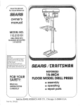
MODEL NO.
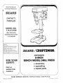
113.213100
DRILL PRESS WiTH
MAXIMUM
DEVELOPED
1/3 HP MOTOR
Serial
Number
Modet and serial number
may be found 01 the let1`
side of the head,
You should record both
model and serial number
in
a safe place for future use.
S_ ARS / £RRFTSMRll®
MOTORIZED
FOR YOUR
SAFETY:
READ ALL
INSTRUCTIONS
L... CAREFULLY
8-INCH
BENCH MODEL DRILL
• assembly
• operating
• repairpads
..//
SEARS, ROEBUCK AND CO., Hoffman
Part No, SP5493
Estates,
IL 60! 79 U.S.A.
Printed in r--h._.,
,._._._,
FULL ONE YEAR WARRANTY ON CRAFTSMAN
DRILL PRESS
if within one year from the date of purchase, this Craftsman Dritl Press falls due to a defect in
material or workmanship, Sears will repair it, free of charge.
WARRANTY SERVICE IS AVAILABLE BY SIMPLY CONTACTING THE NEAREST SEARS SERVICE CENTER/DEPARTMENT THROUGHOUT THE UNITED STATES.
This warranty applies only while this product is used in the United States.
This warranty gives you specific legal rights, and you may also have other rights which vary
from state to state.
SEARS, ROEBUCK AND CO., D/817 WA Hoffman Estates, IL 60195
GENERAL SAFETY INSTRUCTmONS FOR POWER TOOLS
1. KNOW YOUR POWER TOOL
Read and understand the owner's manual and
labels affixed to the tool. Learn its application and
limitations as well as the specific potential hazards
peculiar to this tool.
2. GROUND ALL TOOLS
This tool is equipped with an approved 3-conductor
cord and a 3-prong grounding type plug to fit the
proper grounding type receptacle. The green conductor in the cord is the grounding wire. Never
connect the green wire to a live terminal.
3. KEEP GUARDS IN PLACE
In working order, and in proper adjustment and
alignment.
4. REMOVE ADJUSTING KEYS AND WRENCHES
Form a habit of checking to see that keys and
adjusting wrenches are removed from tool before
turning it on.
5. KEEP WORK AREA CLEAN
Cluttered areas and benches invite accidents. Floor
must not be slippery due to wax or sawdust.
6. AVOID DANGEROUS ENVIRONMENT
Don't use power tools in damp or wet locationsor
expose them to rain. Keep work area well lighted.
Provide adequate surrounding work space.
7. KEEP CHILDREN AWAY
All visitors should be kept a safe distance from
work area.
8. MAKE WORKSHOP CHILD-PROOF
With padlocks, master switches, by removing starter keys, or storing tools where children can't get
them.
9. DON'T FORCE TOOL
It will do the job better and safer at the rate for
which it was designed.
10. USE RIGHTTOOL
Don't force tools or attachment to do a job it was
not designed for.
11. WEAR PROPER APPAREL
Do not wear loose clothing, gloves, neckties, or
jewelry (rings, wrist watches) to get caught in moving parts. NONSLIP footwear is recommended.
Wear protective hair covering to contain long hair.
Roll long sleeves above the elbow.
12. USE SAFETY GOGGLES (HEAD PROTECTION)
Wear safety goggles (must comply with ANSI
13.
14.
15.
16.
17.
18.
19.
Z87.1) at all times. Everyday eyeglasses are not
safety glasses. They only have impact resistant
lenses. Also, use face or dust mask if cutting operation is dusty, and ear protectors (plugs or muffs)
during extended periods of operation.
SECURE WORK
Use clamps or a vise to hold work when practical.
It frees both hands to operate tool.
DON'T OVERREACH
Keep proper footing and balance at all times.
MAINTAIN TOOLS WiTH CARE
Keep tools sharp and clean for best and safest
performance. Follow instructions for lubricating and
changing accessories.
DISCONNECT TOOLS
Before servicing; when changing accessories such
as blades, bits, cutters, etc.
AVOID ACCIDENTAL STARTING
Make sure switch is in "OFF" position before plugging in.
USE RECOMMENDED ACCESSORIES
Consult the owner's manual for recommended accessories. Follow the instructions that accompany
the accessories. The use of improper accessories
may cause hazards.
NEVER STAND ON TOOL OR ITS STAND
Serious injury could occur if the tool is tipped or if
the cutting toot is accidentally contacted. Do not
store materials above or near the tool such that it
is necessary to stand on the too! or its stand to
reach them.
20. CHECK DAMAGED PARTS
Before further use of the tool, a guard or other part
that is damaged should be carefully checked to
ensure that it will operate properly and perform its
intended function. Check for alignment of moving
parts, binding or moving parts, breakage of parts,
mounting, and any other conditions that may affect
itsoperation. A guard or other part that is damaged
should be properly repaired or replaced.
21, DIRECTION OF FEED
Feed work into a blade or cutter against the direction of rotation of the blade or cutter only.
22. NEVER LEAVETOOL RUNNING UNATTENDED
Turn power off. Don't leave tool until it comes to a
complete stop.
2
additiona
SAFETY
safety instructions
SIGNAL
press off and unplug it until the particular
is properly repaired or replaced.
WORDS
DANGER: means if the safety information is not
followed someone will be seriously injured or killed.
WARNaNG: means if the safety information is not
followed someone could be seriously injured or
killed.
CAUTION: means if the safety information
followed someone might be injured.
c. To avoid injury from parts thrown
by the spring,
follow instructions
exactly
as given and shown
in adjusting spring tension
of quill.
is not
d.
To prevent the workpiece
from being torn from
your hands, spinning of the toot, shattering the
tool or being thrown, always
properly
support
your work so it won't shift or bind on the tool:
--
General Safety Instructions for Power Tools. 2
Getting to Know Your Drill Press ........
15
Basic Drill Press Operation .............
19
Adjustments ..........................
21
Maintenance ..........................
22
Stability of Drill Press
If there is any tendency of the drill press to tilt or
move during any use, bolt it to the work bench.
Always position BACKUP
beneath the workpiece)
side of the column.
MATERIAL
(use
to contact the left
,--, Whenever
possible,
position
the WORKPIECE to contact the left side of the column-if
it is too short or the table is tilted,
clamp solidly to the table.
Use table slots
or clamping ledge around
the outside edge
of the table.
If the workpiece is too large to easily support with
one hand, provide an auxiliary support,
7. Location
Use the drill press in a well lit area and on a level
surface clean and smooth enough to reduce the
risk of trips, slips, or falls. Use it where neither the
operator nor a casual observer is forced to stand
in line with a potential kickback.
8. Kickback
Kickback is the grabbing of the workpiece by the
rotating toot. The workpiece can be thrown at very
high speed in the direction of rotation. THIS CAN
CAUSE SERIOUS INJURY. To reduce the possibility of injury from kickback:
Clamp the workpiece firmly to the table whenever
possible.
Buffing or sanding wheels or drums should be contacted on the side moving away from you, not the
side moving toward you.
Use only recommended accessories and follow the
instructions supplied with the accessory.
--
When using a drill press
ten it to a table.
--
Never do any work "FREEHAND"
(handholding workpiece rather
than supporting it
on the table), except when polishing.
--
Securely lock Head to Column,
Table Support to Column, and Table to Table Support
before operating drill press.
Never move the Head or Table while the
--
WSE,
always fas-
tool is running.
9. Protection: Eyes, Hands, Face, Ears and Body
WARNmNG: To avoid being pulled into the
spinning tooa -1. Do NOT wear:
-- gloves
-- necktie
-- loose clothing
-- jewelry
2. Do tie back long hair
a. If any part of your drill Dress is missing, malfunctioning, has been damaged or broken..,
such
as the motor switch, or other operating control.
a safety device or the power cord, turn the dril!
part
b. Never place your fingers
in a position where
they could contact the drill or other cutting tool
if the workpiece
should
unexpectedly
shift or
your hand should slip.
WARNING: For your own safety, do not attempt
to operate your drill press untiJ it is completely
assembled and instalSed according to the
instructions..,
and until you have read and
understand the following:
1.
2.
3.
4.
5.
5.
for drJ! presses
--
Before starting the operation,
jog the motor
switch to make sure the drill or other cutting
tool does not wobble or cause vibration.
--
If a workpiece
overhangs
the table such
that it will fall or tip if not held, clamp it to
the table or provide auxiliary
support.
--
Use fixtures
for unusual
adequately
hold, guide
and
piece.
--
Use the SPINDLE
SPEED
recommended
for the specific operation
and workpiece
material--check
the
inside
of the Belt
Guard for drilling information;
for accessories, refer to the instructions
provided
with the accessories,
operations
to
position work-
f. Never climb on the drill press Table, it could
break or pu!I the entire drill press down on you.
g. Turn the motor Switch Off and put away the
Switch Key when leaving the drill press.
h. To avoid injury from thrown work or tool contact,
do NOT perform layout, assembly, or setup
work on the table while the cutting tool is rotating.
3
10. Use
only accessories designed for this drill
press to avoid serious injury from thrown broken parts or work pieces.
The operation of any power tool can result in foreign objects being thrown into the eyes, which can
result in severe eye damage. Always wear safety
goggles
comply with ANSI Z87.1
(shown on
Package) before commencing power tool operation.
Safety Goggles are available at Sears retail stores.
a. When Cutting Large Diameter Holes:
Clamp the workpiece firmly to the table. Otherwise the cutter may grab and spin it at high
speed.
Use only one piece, cup-type, hole cutters.
DO NOT use fly cutters or multi-part hole cutters
as they can come apart or become unbalanced
in use.
Keep speed below 1,500 RPM.
b. Drum sanders must NEVER be operated on
this drill press at a speed greater than 1800
RPM.
c. Do not install or use any drill that exceeds 7" in
length or extends 6" below the chuck jaws. They
can suddenly bend outward or break.
d. Do not use wire wheels, router bits, shaper cutters, circle (fly) cutters or rotary planers on this
drill press.
11. Note and Follow the Safety Warnings and instructions that Appear on the Panel on the
Right Side of the Head:
WARNING
12. This Drill Press has 3 speeds as listed below:
620 RPM
1300 RPM
3100RPM
See inside of guard for specific placement of belt
on pulleys.
13. Think Safety. Safety is a combination of operator
common sense and alertness at all times when the
drill press is being used.
WARNING: Do not allow familiarity (gained
from frequent use of your drill press) to become
commonplace. Always remember that a
careless fraction of a second is sufficient to
inflict severe injury.
4
glossary
of terms
1. Workpiece
The item on which the cutting operations is being
performed.
2, Drill
The cutting tool used in the drill press to make holes
in a workpiece.
4. Revolutions
Per Minute (R.P._I.)
The number of turns completed
by
in one minute.
a spinning
object
5, Spindle
Speed
The RPM of the spindle.
3. Backup Material
A piece of wood placed between the workpiece and
table ....
it prevents wood in the workpiece from
splintering when the drill passes through the backside of the workpiece .... also prevents drilling into
the table top.
table of contents
Page
Page
General Safety Instructions for Power Tools ......
2
Additional Safety Instructions for Drill Presses .... 3
Glossary of Terms ..........................
5
Table of Contents ...........................
5
Motor Specifications and Electrical
Requirements ..............................
6
Unpacking and Checking Contents .............
7
Table of Loose Parts ........................
7
Location and Function of Controls ..............
9
Assembly ................................
10
Assembly of Base/Column ...............
10
Installation of Table/Support ..............
10
Installing the Head .....................
11
Installing Feed Handles .................
12
Installing the Chuck .....................
12
Installing Belt Guard Knob ...............
13
Tensioning Belt .........................
13
Adjusting the Table Square to Head .......
14
Getting to Know Your Drill Press ..............
15
Spindle Speeds ...........................
16
Feature Descriptions .......................
16
OnoOff Switch
..............................
Basic Drill Press Operation
..................
Installing Drills .........................
Positioning Table and Workpiece
Tilting Table ...........................
Hole Location
.........................
Feeding
..............................
Drilling to Depth
.......................
Depth Scale ............................
Removing the Chuck ....................
Adjustments
..............................
Quill Return Spring ......................
Maintenance
..............................
Lubrication
...............................
Recommended
Accessories
..................
Trouble Shooting
..........................
Repair Parts ...............................
5
17
..........
18
18
19
19
20
20
20
20
21
21
21
22
22
22
23
24
motor specifications and electricam requirements
MOTOR SPECiFiCATiONS
This dri!l press is designed to use a 1725 RPM motor
only. Do not use any motor that runs faster than 1725
RPM. It is wired for operation on 120 volts, 60 Hz.
alternating current.
WARNING: To avoid injury from unexpected
startup, do not use blower or washing machine
motors or any motor with an automatic reset
overload protector.
CONNECTING TO POWER
SOURCE OUTLET
This machine must be grounded while in use to protect
the operator from electric shock.
Plug power cord into a 120V properly grounded type
outlet protected by a 15-amp. dual element time delay
or Circuit breaker.
NOT ALL OUTLETS ARE PROPERLY GROUNDED.
iF YOU ARE NOT SURE THAT YOUR OUTLET, AS
PICTURED BELOW, IS PROPERLY GROUNDED,
HAVE iT CHECKED BY A QUALIFIED ELECTRICIAN.
WARNING: To avoid electric shock, do not touch
the metal prongs on the plug, when installing or
removing the plug to or from the outlet.
This power tool is equipped with a 3-conductor cord
and grounding type plug, approved by Underwriters'
Laboratories. The ground conductor has a green jacket
and is attached to the tool housing at one end and to
the ground prong in the attachment plug at the other
end.
This plug requires a mating 3-conductor grounded type
outlet as shown.
If the outlet you are planning to use for this power tool
is of thetwo prong type, DO NOT REMOVE OR ALTER
THE GROUNDING PRONG IN ANY MANNER. Use
an adapter as shown and always connect the grounding
lug to known ground.
It is recommended that you have a qualified electrician
replace the TWO prong outlet with a properly grounded
THREE prong outlet.
An adapter as shown below is available for connecting
plugs to 2-prong receptacles.
WARNING: The green grounding lug extending
from the adapter must be connected to a
permanent ground such as to a properly
grounded outlet box.
GROUNDING
SCREW
LUG
\
WARNING:
Failure to properly ground this
power tool can cause eiectricution or serious
shock, particularly when used in damp locations, or near metal plumbing, if shocked, your
reaction could cause your hands to hit the cutting tool.
o ou o
IF POWER CORD IS WORN OR CUT, OR DAMAGED iN ANY WAY, HAVE IT REPLACED IMMEDIATELY TO AVOID SHOCK OR FIRE HAZARD.
3-PRONG
PLUG
GROUNDING
PRONG
ALWAYS USE A
PROPERLY GROUNDED
OUTLET
Your unit is for use on ! 20 volts, it has a p_ug that looks
like the one above.
ADAPTER
NOTE: The adapter illustrated is for use only if you
already have a properly grounded 2-prong receptacle.
The use of any extension cord will cause some loss of
power. To keep this to a minimum and to prevent overheating and motor burn-out, use the table below to
determine the minimum wire size (A.W.G.) extension
cord. Use only 3 wire extension cords which have 3prong grounding type plugs and 3-pole receptacles
which accept the tools plug.
Extension
Cord Length
0-25 :Feet
26-50 Feet
51-100 Feet
Wire Size A.W.G.
16
14
!2
WARNING: To avoid injury from unexpected
starting or eaectrica! shock, never connect plug
to out_et until aBlassembay is complete and you
read aH instructions.
Model 113.2!3100
one box.
Drill Press is shipped complete in
!. Unpacking and Checking Contents
a. Separate all "loose parts" from packaging materials and check each item with "Table of Loose
Parts" to make sure all items are accounted for,
before discarding any packing material.
TABLE
OF LOOSE
PARTS
Mtem
Description
A Head Asm ...........................
B Column Suppo_,t Asm ...................
C Owner's Manual ......................
D Box of Loose Paris ....................
E Bag of Loose Parts ...................
F Base ................................
G Table/Support Asm ....................
WARNUNG: Bfany parts are missing, do not
attempt to assembHe drill press, plug in the
power cord, or turn the switch on until the
missing parts are obtained and are
installed correctly.
2. Remove the protective oil that is applied to the
table and column. Use any ordinary household type
grease and spot remover.
WARNING: To avoid fire or toxic reaction, never
use gasoBine, naptha or similar highly
volatile solvents.
3. Apply a coat of paste wax to the table and column
to prevent rust. Wipe all parts thoroughly with a clean
dry cloth.
\
A
C
F
Qty,
1
1
1
1
1
1
1
List of loose parts in the box and bags
M8x1.25-20
Hex Head Screw (3)
Support Lock Handle (1)
M5x0.8-12
Pan Head Screw (1)
Feed Handle (3)
M4 Hex "L" Wrench (1)
_Chuck
Key (1)
Belt Guard Knob (1)
Chuck (1)
Key-Switch (1)
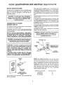
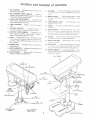
ocation
and function
1, BELT GUARD .°. Covers Pu!teys and be!t during
operation of drill press.
1t.
2, BELT TENSION LOCK. HANDLE,..
Tighteni_g
handles locks motor bracket suppo_ to maintain
correct belt distance and tension.
COLUMN ,.. Conp, ects head, table, and base or_
a one-piece
tube for easy alignment
and moveme_t.
12. BEVEL SCALE . . . Shows
for bevel ope_at:ons.
Scate
support.
3. HEAD LOCK SET SCREWS, ° o Locks the head
to the column. ALWAYS have them locked in place
while operating the drill press.
4_
of controWs
13. TABLE
position
TABLE SUPPORT ° o. Rides on column to support
table.
'
BEVEL LOCK
frorn 0 -45",
14, TABLE o ..
workpiece.
5. COLU_V]N SUPPORT
o , . Supports column and
provides mounting holes for column to base
Provides
degree table is tiited
is mounted on table
. . o Locks the table in any
working
surface
to support
15. FEED HANDLE...
Moves the chuck up or down.
One or two of the handles may be removed
if
necessary whenever
the workpiece is of such u;qLJsual shape that Jt interferes with the handies.
6o SUPPORT LOCK HANDLE,..
Tightening locks
table support to column. Always have it locked in
place while operating the Drill Press.
16. CHUCK...
_{ccessory
7, BASE. o ° Supports Dri!l Press, For additional stabi!ity, holes are provided in base to bolt Drill Press
to bench. (See "Additional Safety Instructiorls Ior
Dril! Presses").
Holds drill bit or other recommended
to perform desired operations.
17, FEED STOP ROD...
to specific depths,
Holds step nuts for ddiiing
18, STOP NUTS...
Limits the downward movement
of the quill at any desired point within its travel,
and prevents the pointer from moving upward,
8, SPR_NG CAP o,, Provides means to adjust quill
spring tension.
9, DEPTH POINTER...
_ndicates drilling depth and
is located above stop nuts,
19. ON-OFF SWITCH...
Has locking feature
vent unauthorized
and possible hazardous
chiidren and others.
!
10. DEPTH SCALE . . , Shows depth of hole being
dri!led in inches and millimeters.
BELT
to preuse by
GUARD
\
8
SPRING
CAP
9
DEPTH
POINTER
19
2
ON-OFF
BELT
TEMS|
LOCK:
10
DEPTH
HANDLE
SCALE
3
16_
CHUCK
HEAD LOCK
SET SCRE¼_S
4
TABLE
SUPPORT
FEED
SPRING
ADJUSTMENT
15
FEED
HANDLE
18
STOP
17
FEED
STOP
!4
NUTS
TABLE
ROD
12
BEVEL
SCALE
TABLE
BEVEL
13
/"
6
SUPPORT LOCK
HANDLE
LOCK
TABLE
REMOVED
FOR CLARITY
5
COLUMN
SUPPO
_--_
ON
assembly
[
'
WARNING:
To avoid injury from unexpected
I starting
or electrical
shock, never connect plug
1 to outlet unti! aH assembly
stepsare
completed
and you
COMBINATgON
read a!l instructions,
Check
TOOLS
NEEDED
MEDIUM PHILLIPS
SCREWDRIVER
MUST
THIS
ASSEMBLY
I,
DIA
x 20ram
below.
STRAIGHT
BOARD
EDGE
3/4'
";'HIS EDGE
PERFECTLY
EDGE___._,I___/__;_'
84NCH
ADJUSTABLE
WRENCH
SHOULD
BE NO GAP
SQUARE
iS FLIPPED
OR OVERLAP
OVER
MUST BE
STRAIGHT
WHEN
IN DOTTED
LONG
POSIT_ON
COL..UMN
ASSEMBLY
BOLT
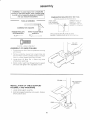
OF BASE/COLUMN
Position base on floor, Remove protective
and discard
covering
2, Remove protective sleeve flora coiumn tube and
discard, PIace column assembiy on base, and align
holes in column support with holes in base,
3, Locate
among
three (3) 8ram Dia, x 20ram
loose pa_ts bag.
tong
bolts
4, tnsta!l a bott in each hole through column support
and base and tighten with adjustable wrench,
\
BASE
COLUMN
TABLE/SUPPORT
ASSEMBLY
INSTALLATION
OF TABLE/SUPPORT
ASSEMBLY
AND HARDWARE
I.
Locate tabte!suppod
as,_;mb y
2. Slide table/support assembly
directiy above base.
onto cotumn. Position
BASE
10
OF
THICK
SQUARE
_'-8ram
BE TRUE.
as Uiustrated
DRAW LIGHT
L_NE ON BOARD
A LONG
COt_B_NATgON
SQUARE
ifts accuracy
TABLf_£
SUPPORT
support
lock handle
among
TABL_
Locate
4.
h-_stail support lock i_and/e from ieft side into table
st._pporl, Raise tabie to workin 9 height by siidin 9 it
on the columr_ and then tighten iock har_die by
hand.
S U P P O R T ......
LOCK HANDLE
3,
!oose parts.
COLUMN
/
/
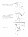
INSTALLING
[
THE
HEAD
CAUTION:
The head assembly
weighs
25 pounds.
Carefully
lift head.
Remove
t.
protective
l
1/7<_<
covering
about
_}
/
J
HE
from head.
2. Carefully lift head above column tube and slide it
down on the column as far as it will go. Align head
with table and base.
COLUMN
HEAD LOCK
SET SCREWS
+
Using a 4mm Hex '%" wrench tighten the head lock
set screws on the right side of the head,
HEAD
11
iNSTALLiNG
FEED HANDLES
1. Locate three (3) feed handles among loose parts.
2. Screw the feed handles tightly into the threaded
holes in the hub.
INSTALMNG
FEED
HANDLE
THE CHUCK
1. Locate the chuck among loose parts.
2. Clean out the TAPERED HOLE in the chuck; clean
the spindle nose with a clean cloth. Make sure
there are no foreign particles sticking to the surfaces. The slightest piece of dirt on the spindle
nose or in the chuck will prevent the chuck from
seating properly. This will cause the drill to
"wobble."
NOTE: If TAPERED HOLE in the chuck is extremely dirty, use a cleaning solvent on the clean
cloth,
CHUCK
_
3. Push the chuck up on the spindle nose as far as
it will go.
4. Turn chuck sleeve clockwise and open jaws in
chuck completely,
5. Lightly tap the nose of the chuck with a piece of
wood to insure proper seating of the chuck on the
spindle.
NOSE
SPINDLE
CHUCK
12
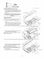
\
HUB
5mm DIA, × 12ram LONG
CROSS RECESS SCREW
BELT
GUARD
INSTALLING
KNOB
BELT GUARD
KNOB
1. To attach belt guard knob, use knob and 5mm Dia.
x 12mm long pan hd. screw in loose parts bag. tnstalf
screw in hole located in guard and attach knob, turning until tight.
PAN HD.
SCREW
WARNING: To avoid possibHe injury keep guard
in place and in proper working order while
operating.
TENS_ONING
BELT
NOTE: The Drill Press is shipped with the belt installed,
but it should be properly tensioned before use.
1. Lift guard from right side and leave opened on
hinge.
2. Release Belt Tension Lock Handle located on right
side of Drill Press head. Puit right side of motor
toward front of dHII press to relieve spring tension
on belt. Tighten the belt tension lock handle.
3. Choose speed for drilling operation, and move belt
to correct position for desired speed.
NOTE: Refer to chart inside belt guard for Recommended Drilling Speeds.
4. Loosen belt tension lock handle and move right
side of motor rearward to apply tension to the belt.
5. Tighten Belt Tension Lock Handle.
NOTE: Belt SHOULD deflect approximately 1/2" by
thumb pressure at mid-point of belt between pulleys.
6. Close belt guard.
7. If belt slips while drilling, readjust belt tension.
i
13
LOCK
HANDLE
ADJUSTING
HEAD
THE
TABLE
SQUARE
TO
NOTE: The combination square must be "true." See
the beginning of the "Assembly" section for a method
to check four square.
1. Insert precision round steel rod or straight drill bit
approximately 3" long into chuck and tighten.
2. With table raised to working height and locked on
column, place combination square flat on table beside rod.
ROD
COMBINATION
SQUARE
[
I
3. If an adjustment is necessary, loosen the table
bevel lock bolt with adjustable wrench. (This adjustment is located under the table).
4. Align the table square to the rod by tilting table.
5. Retighten table bevel lock bolt.
TABLE
BLE BEVEL
LOCK BOLT
14
9 tt_ng to know your
e
ddli press
1
BELT
GUARD
/
15
FEED
HANDLE
2
19
ON-OFF
BELT
SWITCH
TENSION
HANDLE
LOCI4
3
HEAD LOOK
SCREWS
FEED SPRING
ADJUSTMENT
16
4
CHUCK
FEED
SPRING
TABLE
SUPPORT
9
DEPTH
POINTER
14
TABLE
18
. STOP
NUTS
COLUMN
5
COLUMN
8
SPRING
7
CAP
BASE
"_
FEED
STOP
10SCALE
ROD
SPINDLE
ASSEMBLY
OF DRILL PRESS
13
6
SUPPORT
DEPTH
LOCK
TABLE
HANDLE
BEVEL
_ _..______
SPUNES
LOCK
12
BEVEL
SCALE
TABLE REMOVED
FOR CLARITY
CHUCK
CHUCK
KEY
15
SUPPOF:tT
S, ET
This Drill Press has 3 speeds as listed below:
620 RPM
1300 RPM
3100 RPM
SPINDLE
SPEEDS
iN R.P.M°
See inside of belt guard for specific placement of belts
on pulleys.
Feature Descriptions
1. BELT GUARD...
Covers pulleys and belt during
operation of drill press.
2. BELT TENSION LOCK HANDLE...
Tightening
handle locks motor bracket support to maintain correct belt distance and tension,
13. TABLE BEVEL LOCK...
position from 0o-45 o.
14. TABLE •..
workpiece.
Rides on column to support
5. COLUMN SUPPORT . . . Supports column and
provides mounting holes for column to base,
6. SUPPORT LOCK HANDLE...
Tightening locks
table support to column. Always have it locked in
place while operating the Drill Press.
17. FEED STOP ROD,..
Holds stop nuts for drilling
to specific depths.
18, STOP NUTS.,.
Limits the downward movement
of the quill at any desired point within its travel.
!9, ON-OFF SWITCH ... Has locking feature. THIS
FEATURE IS INTENDED TO PREVENT UNAUTHORIZED AND POSSIBLE HAZARDOUS USE
BY CHILDREN AND OTHERS.
7. BASE...
Supports Drill Press. For additional stability, holes are provided in base to bolt Drill Press
to bench (See "Additional Safety Instructions for
Drill Presses,")
8. SPRING CAP,..
spring tension.
Provides working surface to support
15. FEED HANDLE ... For moving the chuck up or
down. One or two of the handles may be removed
if necessary whenever the workpiece is of such
unusual shape that it interferes with the handles.
16. CHUCK ... Holds drill bit or other recommended
accessory to perform desired operations,
3. HEAD LOCK SET SCREWS...
Locks the head
to the column. ALWAYS have them locked in place
while operating the drill press,
4. TABLE SUPPORT...
table.
Locks the table in any
20, CHUCK KEY, . . It is a self-ejecting chuck key
which will "pop" out of the chuck when you'let go
of it. This action is designed to help prevent throwing of the chuck key from the chuck when power
is turned "ON". Do not use any other key as a
substitute, order a new one if damaged or lost.
Provides means to adjust quill
9. DEPTH POINTER...
Indicates drilling depth,
10. DEPTH SCALE...
Shows depth of hole being
drilled in inches and millimeters.
21. BELT TENSION...
Belt" (Page 13).
11. COLUMN...
Connects head, table, and base on
a one-piece tube for easy alignment and movement.
Refer to section "Tensioning
22, DRiLLiNG SPEED.,. Can be changed by placing
the belt in any of the STEPS (grooves) in the pulleys. See Spindle Speed chart inside belt guard.
12. BEVEL SCALE...
Shows degree table is tilted
for bevel operations. Scale is mounted on table
support, if it is to be used for quick reference where
accuracy is not critical.
To determine the approximate drilling speed, refer to
the table inside the belt guard.
16
ONoOFF SW_TCH
Insert KEY into switch.
NOTE: Key is made of Yellow plastic.
/
To turn drill ON,,.
Insert finger under switch lever and puli.
\
To turn drill OFF...
Push lever in.
In an emergency: If the drill bit BINDS.., STALLS...
STOPS...or tends to tear the workpiece loose...you
can QUICKLY turn the drill OFF by hitting the switch
with the palm of your hand.
To lock switch in OFF position,,,
hold switch IN with
one hand...
REMOVE key with other hand.
WARNING: For your own safety, always lock
the switch "Off" when drill press is not in
use.,,
remove key and keep it in a safe place
, • • also..,
in the event of a power failure (all
of your lights go out) or blown fuse or tripped
circuit breaker, turn switch off..,
lock it
and remove the key. This will prevent the drill
press from starting up again when the
power comes back on.
!7
basic drill press operation
--
Securely tock Head to Column, Table Sup.port to Column, and Tabte to Table Support
before operating dril! press.
-- Never move the Head or Table while the
tool is running.
-- Before starting the operation, jog the motor
switch to make sure the drill or other cutting
tool does not wobble or cause vibration.
-- If a workpiece overhangs the table such that
it will fall or tip if not held, clamp it to the
table or provide auxiliary support,
-- Use fixtures for unusual operations to
adequately hold, guide and position workpiece.
-- Use the SPINDLE SPEED recommended
for the specific operation and workpiece maN.
terial--check
the panel inside the guard
cover for drilling information; for accessories, refer to the instructions provided with
the accessories.
f. Never climb on the drill press Tabte, it could
break or pull the entire drill press down on you.
g. Turn the motor Switch Off and remove the
Switch Key when leaving the drill press.
h. To avoid injury from thrown work or tool contact,
do NOT perform layout, assembly, or setup
work on the table while the cutting tool is rotating.
Follow the following instructions for operating your drill
press to get the best results and to minimize the likeUihood of personal injury.
WARNING: For your own safety, aSways observe
the safety precautions here and on
pages 2, 3, and 4,
1. Protection: Eyes, Hands, Face, Ears and Body
WARNING: To avoid being pulled into the
spinning tool -1. Do NOT wear:
- gloves
-- necktie
- loose clothing
- jewelry
2. Do tie back long hair
a,
b,
c,
d.
If any part of your drill press is missing, malfunctioning, has been damaged or broken..,
such
as the motor switch, or other operating control,
a safety device or the power cord, turn the drill
press off and unplug it until the particular part
is properly repaired or replaced.
Never place your fingers in a position where
they could contact the drill or other cutting tool
if the workpiece should unexpectedly shift or
your hand should slip.
2. Use onJy accessories designed for this drill
press to avoid serious injury from thrown broken parts or work pieces.
a. When Cutting Large Diameter Holes:
Clamp the workpiece firmly to the table. Otherwise the cutter may grab and spin it at high
speed.
To avoid injury from, parts thrown by the spring,
follow instructions exactly as given and shown
in adjusting spring tension of quill.
To prevent the workpie,ce from being torn from
your hands, spinning of the tool, shattering the
tool or being thrown, always properly support
your work so it won't shift or bind on the tool:
-- Always position BACKUP MATERIAL (use
beneath the workpiece) to contact the left
side of the column.
-- Whenever possible, position the WORKPIECE to contact the left side of the column-if it is too short or the table is tilted,
clamp solidly to the table. Use table slots or
clamping ledge around the outside edge of
the table.
-- When using a drill press VISE, always fasten
it to a table.
-- Never do any work "FREE HAND" (handholding workpiece rather than supporting it
on the table), except when polishing.
INSTALLING
Use only one piece, cup-type, hole cutters.
DO NOT use fly cutters or multi-part hole cutters
as they can come apart or become unbalanced
in use.
Keep speed below 1,500 RPM.
b. Drum sanders must NEVER be operated on
this drill press at a speed greater than 1800
RPM.
c. Do not install or use any drili that exceeds 7" in
length or extends 6" below the chuck jaws. They
can suddenly bend outward or break.
d. Do not use wire wheels, router bits, shaper cutters, circle (fly) cutters or rotary planers on the
drill press.
DRILLS
CHUCK KEY
Insert drill into chuck far enough to obtain maximum
GRIPPING of the CHUCK JAWS . . . the jaws are
approx. 1" long. When using a small drill do not insert
it so far that the jaws touch the flutes (spiral grooves)
of the drill.
CHUCK
Make sure that the drill is CENTERED in the chuck
before tightening the chuck with the key.
Tighten the drill sufficiently, so that it does not SLIP
while drilling.
Turn the chuck key clockwise
terclockwise to loosen.
JAWS
to tighten--coun18
POSiTiONiNG
TABLE
AN{}
WORKP_ECE
Lock the table to the coiumn in a position so that the
tip of the drill is just a iittle above the top of the work piece,
A_ways place a piece of BACK-UP
t_4ATERtAL (wood.
plywood . . .) on the table underneath
the wo_kpi_:_ce.
This will prevent "splintering"
or making a heavy bur_
on the underside on the workpiece
as the drill breaks
through. To keep the backup material
from spinning
out of control, it must contact the left side of the coiumn,
as illustrated.
WARNING:
To prevent
workpiece
or the
backup
material from being torn from your
hand while driHi_J, position
the_'_ against the _eft
side of the eo_um_o _f the workpiece
or the
backup
materia_ are not tor_g enough
to reach
the coBumn, o_amp them to the table° Failure to
do this could result in personal
injury_
BACK°U
_
MATER_AL
WORKP_'ECE,
For small pieces that cannot be c_amped to the tabie,
use a dril! press vise (Qptiona! accessory).
DRILLwsEPRESS
WAIRNBNG: The vise must be emamped or bolted
to the table to avoid inju_'y 1'rein spinning
work and vise or tooU breakage,
BOLT OR
CLAMP
ViSE
TgLTING
TABLE
To use the table in a bevel (tilted) position,
the bevel lock with adjustable wrench.
Tilt table
Retighten
to desired
angle
by reading
loosen
BEVEL
LOCK
bevel scale.
bevel lock.
BEVEL
SCALE
19
WARNING: To avoid injury from spinning work
or tool breakage, always clamp workpiece and
backup material securely to table before
operating drill press with the table tilted.
Before turning the switch ON, bring the drill down to
the workpiece lining it up with the hole location.
FEEDING
Pull down on the feed handles with only enough effort
to allow the drill to cut,
'To return table to original position: loosen the bevel
lock, tilt table back to 0° on bevel scale, and retighten
bevel lock.
Feeding TOO SLOWLY might cause the drill to burn
•.. Feeding TOO RAPgDLY might stop the motor...
cause the belt or drill to SLiP...
tear the workpiece
LOOSE or BREAK the drill bit.
HOLE LOCATION
When drilling metal it may be necessary to lubricate
the tip of the drill with cutting oil or motor oil to
prevent burning of the drill tip.
Make an indentation in the workpiece where you want
the hole..,
using a CENTER PUNCH or a SHARP
NAIL,
DRtLLUNG
TO DEPTH
To drill a BLIND hole (not all the way through) to a
given depth, can be done two ways.
pEPTH
STOP
1. Mark the depth of the hole on the side of the workpiece.
2. With the switch OFF bring the drill bit down until
the TIP or lips are even with the Mark.
3. Spin the lower nut down to contact the depth stop
tug on the Head.
4. Spin the upper nut down and tighten against the
lower nut.
ANOTHER
MARK
WAY -- DEPTH SCALE
1. Turn the switch off.
2. Place workpiece on table. Raise table until tip of
drill touches top of workpiece. Remove workpiece
from table.
DEPTH
SCALE
3. Turn the feedhandle until the pointer points to the
desired depth on the depth scale.
DEPTH
STOP
4. Hold the feed handle at this position.
5. Spin the lower stop nut down until it touches the
depth stop.
6. Spin the upper stop nut down against the tower
stop nut and tighten.
7. The chuck or drill will now be stopped after traveling
downward the distance selected on the depth
scale.
2O
UPPER
LOWER
STOP NUT
STOP NUT
SLEEVE
REMOVING
_----_
I
\_
THE CHUCK
1. Open jaws of chuck as wide as they will go by
turning chuck sleeve.
CHUCK
L_L(
F_
I\\
2. Carefully tap chuck with mallet in one hand while
holding chuck in other hand to prevent dropping it
when released from spindle nose.
SPRING CAP
adjustments
NOTCH
BOSS
WARNING: For your own safety turn switch "Off"
and remove plug from power source outlet
before making any adjustments. To avoid injury
from thrown parts due to spring release, follow
instructions carefully and wear eye goggles.
QUILL
RETURN
\l
JAM NUT
(OUTER)
SPR1NG
STANDARD
NUT
(INNER)
1. Move the stop nuts down to their lowest position
and lock in place with wrench to prevent quill dropping while tensioning spring.
2. Lower table for additional clearance.
3. Work from left side of Drill Press.
STOP
NUTS
4. Place screwdriver in lower front notch of spring
cap, and hold it in place while loosening and removing jam [outer] nut only.
5. With screwdriver remaining in notch, loosen large
standard [inner] nut (approximately 1/8") until notch
disengages from boss on head. DO NOT REMOVE
THIS NUT.
6. Carefully turn screwdriver counter clockwise and
engage next notch in boss. DO NOT REMOVE
SCREWDRIVER.
7. Tighten standard nut with wrench only enough to
engage boss. Do not overtighten as this will restrict
quill movement.
8. Move stop nuts to upper most position and check
tension while turning feed handles.
9. If there is not enough tension on spring, repeat
steps 4-8 moving only ONE notch each time and
checking tension after EACH repetition.
10. Proper tension is achieved when quill returns gently
to full up position when released from 3/4" depth.
12. Check quill while feeding to have smooth and unrestricted movement. If movement is too tight,
loosen jam nut and SLIGHTLY loosen standard
nut until unrestricted. Retighten jam nut.
1 1. When there is enough tension after checking, replace jam nut and tighten to standard nut, BUT do
not overtighten against standard nut.
21
maintenance
"Off" and remove plug from power source outlet
I before
WARNING:
For your
own safety,
turndrill
switch
maintaining
or lubricating
your
press.
_wGREEN
iRE
8LACK,
__
CONN
Frequently blow out any dust that may accumulate inside the motor.
A coat of automotive type paste wax applied to the
table and column will help to keep the surfaces
clean.
WARNING: To avoid shock or fire hazard, if the
power cord is worn or cut, or damaged in any
way, have it replaced immediately.
Wiring Diagram
SPINDLE ASSEMBLY
OF DRILL PRESS
1_.,,-----H
SPLINES
(GROOVES)
lubrication
All of the BALL BEARINGS are packed with grease at
the factory, They require no further lubrication.
Periodically lubricate the SPLINES (grooves) in the
spindle, and the RACK (teeth of the quill).
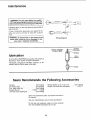
Sears Recommends
Drill Bits .........................
See
Drill Press Vises ...................
See
5 pc, Stop Collar Set ...............
See
Sanding Drums ................
9-2497 -I5 Piece Drum Sanding Kit ..........
See
the Following Accessories
Buffing Wheels up to 4" dia. max ......
See Catalog
Power Tool Know-How Handbook ........
9-291 !7
Catalog
Catalog
Catalog
9-2498
Catalog
Sears may recommend other accessories not listed in
the manual.
See your nearest Sears store for other accessories.
Do not use any accessory unless you have received
and read complete instructions for its use.
22
trouble
shootir g
WARNING: For your own safety, turn switch
"Off" and always remove plug from power
source out_et before troubSe shooting.
® CONSULT YOUR LOCAL SEARS
pROBABLE
TROUBLE
Noisy Operation
SERVICE CENTER IF FOR ANY REASON MOTOR WILL NOT RUN.
REMEDY
CAUSE
1. Adjust tension, See section
"ASSEMBLY--TENSIONING
BELT."
2. Lubricate spindle. See "Lubrication"
section.
3. Checking tightness of retaining nut on
pulley, and tighten if necessary.
4. Tighten setscrews in pulleys.
1. Incorrect belttension.
2. Dry Spindle.
Drill Bit Burns
3. Loose
spindle
4, Loose
motor
1, Incorrect
pulley.
pulley.
1. Change speed. See section "Getting
To Know Your Drill Press"...
DRILLING SPEED.
2. Retract drill bit frequently to clear chips.
3. Resharpen drill bit.
4. Feed fast enough...allow drill bit to cut.
5. Lubricate drill bit. See "Basic Drill Press
Operation" section.
speed.
2. Chips notcomingout
of hole.
3. Dull Drill Bit.
4. Feeding too slow.
5. Not lubricated.
Drill bit leads off...
hole not round.
1. Resharpen drill bit correctly.
Hard grain in wood or
lengths of cutting
lips and/or angles
not equal.
2. Bentdrill bit.
2. Replace drill bit.
Wood splinters on
underside,
1. No "back-up material"
under workpiece.
1. Use"back-up material"... See Basic
Drill Press Operation" section.
Workpiece torn
loose from hand.
1. Not supported or
clamped properly.
1. Support workpiece or clamp it... See
"Basic Drill Press Operation" section.
Drill bit Binds in
workpiece.
1. Workpiece pinching drill bit
or excessive feed pressure.
2. Improper belt tension.
1. Support workpiece or clamp it... See
"Basic Drill Press Operation" section.
2. Adjusttension...
See section
"ASSEMBLY--TENSIONING
BELT."
Excessive drill bit
runout or wobble.
1. Bent drill bit.
2. Worn spindle bearings.
3. Drill bit not properly
installed in chuck.
4. Chuck not properly installed.
1. Use a straight drill bit.
2. Replace bearings
3. Install drill bit properly...See "Basic
Drill Press Operation" section.
4. Install chuck properly.., refer to
"Unpacking and Assembly Instruct!.: ns
. .. INSTALLING THE CHUCK/'
Quill Returns
too slow or too
fast.
1. Spring has impropertension.
1. Adjust spring tension... See section.
"Adjustments--Quill Return Spring."
Chuck will not stay
attached to spindle
it falls off when
trying to install it.
1.
1.
Dirty, grease, or oil on the
tapered inside surface of chuckor on the spindles tapered
surface.
23
1. Using a household detergent-clean the
tapered surface of the chuck and spindle to
remove all dirt, grease and oil.
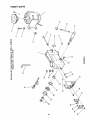
repair parts
/
o%
o
@
_L
.J
\
\
a_
///
/
_F
w'-
LH
td
U.
Ouj
rrC_
oo
@@
O9
.J
(n
e')
n_
<
(I.
o
24
repair
parts
C
0
0oc5
o_
._x
CL L_
_
E
m
o
_
E
_'3
_g
?-
....
k.,
0
8
o
©
,_
©
O
5
a
t0
_0
o9
uJ
COd) CO0")
©_dO001I
COOZZ
n
0
_0
rr
J_
E
0
.J
_J
Z
tr
0
60
_
_o
cO
r
©
o
0
0
J_
_D
b--
_C,
oO oo
CO cO
cO
z
o4
E
Z
w
oo
d
Z
0
E
z
D
0
"E
LL
%, 5d
r,o
nO 0
U.
_0
LO
_o
x
.9
0
.J
0
0
Q
'
c_
•
__
x
0
_
Y3
.
"
C,
"-09
_ -5o
@
I
n_ e_
_X__ ,.z l..U,
,
ooo.
co
c
,T_
,--'_
C_ 0,.I
O0
I
Ec5
o×4 .
__o_
___
_
_
OJ
f
oo
o
OJ
.r--
0
00
0'_
E_
B
.m
0
_0_
o._
CO
>"
_-_
E
<Dr
U) T
w
000009090000
00
e000
0000
C00_0Dr...0
o009o0
co
25
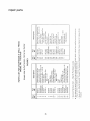
repair parts
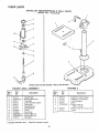
PARTS
LiST FOR CRAFTSMAN 8" DRILL PRESS
MODEL NO. 113.213100
3
2
\
14
1
15
Always order by Part Number--Not
FIGURE
Key
No.
Part
No.
Description
by Key Number
2
Key
No.
Part
No.
Description
8
9
10
11
12
13
14
15
STD315235
817408
817407
817426
817440
63418
816755-6
820294
*Bearing-Ball 17mm
Spacer
Insert-Pulley
Pulley-Spindle
Nut-Pulley
Clamp Cord
Screw Pan Hd, M5 x 0.8-16
Washer, Foam
i
1
2
3
4
5
6
817451-1
817325
816755-4
817428
817779
817358
817453-1
Bushing-Rubber
Knob
Screw-Pan Hal. M5 x 0.8-12
Belt-"V" 5/16 x 26
Guard w/Labels
Screw-Washer Hd.
M6x1.0-16
Ring Retaining
* Standard Hardware Item -- May Be Purchased Locally.
26
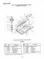
repair parts
O
PARTS
MST FOR CRAFTSMAN
8" DRILL
MODEL NO. 113.213100
jt
1
7
12
11_"_'_
"_"
4
Always order by Part Number--Not
FIGURE
3 QUILL
Key
No,
Part
No.
1
2
3
4
5
6
7
8
9
10
11
!2
817413
STD315215
817411
816755
817414
817453
817410
817340-1
817339-1
STD840610
STD840508
817418
PRESS
by Key Number
FIGURE
ASSEMBLY
Description
Gasket-Quill
* Bearing-Ball 12mm
Tube-Quill
Screw-Pan M5 x 0.8-20
Collar-Stop
Ring-Retaining
Shaft-Spindle
Chuck
Key-Chuck
*Nut-Hex M6x 1.0
*Nut-Hex M5 x 0.8
Rod-Stop
* Standard Hardware Item -- May Be Purchased Locally.
27
Key
No.
Part
No.
1
2
3
4
5
817773
817290
817432
817431
STD835020
6
7
817447
817437
4
Description
Support-Table
w!Scale
Support-Lock
Handle
Tube/Support
Base
* Screw-Hex
Hd.
M8 x 1.25-20
Screw-Hex
Table
Hd. 1/2-12 x 7/8
MOTORIZED
For the repair or replacement parts you need
Call 7 &m - 7 prn, 7 days a week
MODEL NO.
t oOOOo3G6oPART
] ] 3.213100
(1-880-305-7278)
DRILL PRESSWITH
MAXIMUM
DEVELOPED
1/3 HP MOTOR
For in-home major brand repair service
Call 24 hours a day, 7 days a week
1-800=4-REPA|R
(1-800-473-7247)
The model number of your
Drill Press will be found on a
plate attached to the left
side of the head.
When requesting service or
ordering parts, always provide the following information:
For the location of a
Sears Repair Service Center in your area
Call 24 hours a day, 7 days a week
1-800-488-1222
• Product Type
• Model Number
• Part Number
• Part Description
For information on purchasing a Sears
Maintenance Agreement or to inquire
about an existing Agreement
Call 9 am - 5 pro, Monday-Saturday
1-800-827-6655
SWARS
Amenca's
Repair
Spec_ahsts
J
SEARS, ROEBUCK
Part No SP5493
j
AND
CO.,
Hoffman
Form No SP5493-3
Estates,
IL 60179
U,S,A,
Printed
in '-'h___,
,_''_u10195