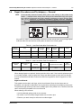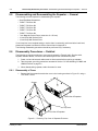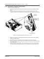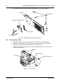
1
Professional Digital Two-Way Radio System
MOTOTRBO™ Repeater
Basic Service Manual
DR 3000 Repeater
Title Page
M
DR 3000
UHF Range 1
MOTOTRBO™ Repeater
Basic Service Manual
6866576D03-A
Foreword
This manual covers all models of the MOTOTRBO Repeater, unless otherwise specified. It includes all the information
necessary to maintain peak product performance and maximum working time, using levels 1 and 2 maintenance
procedures. This level of service goes down to the board replacement level and is typical of some local service centers,
Motorola Authorized Dealers, self-maintained customers, and distributors.
For details on repeater operation or component-level troubleshooting, refer to the applicable manuals available separately.
Product Safety and RF Exposure Compliance
!
Caution
Before using this product, read the operating instructions
for safe usage contained in the Product Safety and RF
Exposure booklet enclosed with your product.
ATTENTION!
This repeater is restricted to occupational use only to satisfy ICNIRP/FCC RF energy exposure
requirements. Before using this product, read the RF energy awareness information and operating
instructions in the Product Safety and RF Exposure booklet enclosed with your product (Motorola
Publication part number 6866537D37) to ensure compliance with RF energy exposure limits.
For a list of Motorola-approved antennas, and other accessories, visit the following web site which
lists approved accessories: http://www.motorola.com/governmentandenterprise
Computer Software Copyrights
The Motorola products described in this manual may include copyrighted Motorola computer programs stored in
semiconductor memories or other media. Laws in the United States and other countries preserve for Motorola certain
exclusive rights for copyrighted computer programs, including, but not limited to, the exclusive right to copy or reproduce in
any form the copyrighted computer program. Accordingly, any copyrighted Motorola computer programs contained in the
Motorola products described in this manual may not be copied, reproduced, modified, reverse-engineered, or distributed in
any manner without the express written permission of Motorola. Furthermore, the purchase of Motorola products shall not
be deemed to grant either directly or by implication, estoppel, or otherwise, any license under the copyrights, patents or
patent applications of Motorola, except for the normal non-exclusive license to use that arises by operation of law in the
sale of a product.
Document Copyrights
No duplication or distribution of this document or any portion thereof shall take place without the express written permission
of Motorola. No part of this manual may be reproduced, distributed, or transmitted in any form or by any means, electronic
or mechanical, for any purpose without the express written permission of Motorola.
Disclaimer
The information in this document is carefully examined, and is believed to be entirely reliable. However, no responsibility is
assumed for inaccuracies. Furthermore, Motorola reserves the right to make changes to any products herein to improve
readability, function, or design. Motorola does not assume any liability arising out of the applications or use of any product
or circuit described herein; nor does it cover any license under its patent rights nor the rights of others.
Trademarks
MOTOROLA and the Stylized M logo are registered in the U.S. Patent & Trademark Office. All other product or service
names are the property of their respective owners.
© 2007 by Motorola, Inc.
All rights reserved.
iii
Document History
The following major changes have been implemented in this manual since the previous edition:
Edition
6866576D03-A
6866576D03-A
Description
Initial Release
Date
Feb. 2007
February 21, 2007
iv
Notes
February 21, 2007
6866576D03-A
Table of Contents
v
Table of Contents
Foreword .........................................................................................................ii
Product Safety and RF Exposure Compliance ............................................................................................ii
Computer Software Copyrights ...................................................................................................................ii
Document Copyrights ..................................................................................................................................ii
Disclaimer....................................................................................................................................................ii
Trademarks .................................................................................................................................................ii
Document History ........................................................................................ iii
Chapter 1
1.1
1.2
1.3
1.4
1.5
Notations Used in This Manual .................................................................................................... 1-1
Repeater Description ................................................................................................................... 1-1
MOTOTRBO Repeater Model Numbering Scheme..................................................................... 1-2
UHF1 High Power MOTOTRBO Repeater (403-470 MHz) Model Chart..................................... 1-3
Specifications............................................................................................................................... 1-4
Chapter 2
2.1
2.2
2.3
5.3
5.4
5.5
Repeater Tuning and Programming .................................. 4-1
Introduction .................................................................................................................................. 4-1
Customer Programming Software Setup ..................................................................................... 4-1
Repeater Tuning Setup................................................................................................................ 4-2
Chapter 5
5.1
5.2
Transceiver Performance Testing ..................................... 3-1
General ........................................................................................................................................ 3-1
Setup ........................................................................................................................................... 3-1
Chapter 4
4.1
4.2
4.3
Test Equipment and Service Aids ..................................... 2-1
Recommended Test Equipment .................................................................................................. 2-1
Service Aids................................................................................................................................. 2-2
Programming Cables .................................................................................................................. 2-2
Chapter 3
3.1
3.2
Introduction ......................................................................... 1-1
Disassembly/Reassembly Procedures ............................. 5-1
Introduction .................................................................................................................................. 5-1
Preventive Maintenance .............................................................................................................. 5-1
5.2.1 Inspection ........................................................................................................................ 5-1
5.2.2 Cleaning Procedures ....................................................................................................... 5-1
Safe Handling of CMOS and LDMOS Devices ............................................................................ 5-2
Repair Procedures and Techniques — General .......................................................................... 5-3
Disassembling and Reassembling the Repeater — General ...................................................... 5-4
6866576D03-A
February 21, 2007
vi
Table of Contents
5.6
5.7
5.8
5.9
5.10
Disassembly Procedures — Detailed .......................................................................................... 5-4
5.6.1 Disassembly of Cover...................................................................................................... 5-4
5.6.2 Disassembly of Repeater Indicator Board ....................................................................... 5-5
5.6.3 Disassembly of Fan ......................................................................................................... 5-6
5.6.4 Removing Transmit Radio ............................................................................................... 5-7
5.6.4.1 Removing Thermal Pad and Heatsink .............................................................. 5-8
5.6.5 Removing Receive Radio, Power Supply and Connector Board Assembly .................... 5-8
5.6.5.1 Disassembly of Receive Radio ....................................................................... 5-10
5.6.5.2 Disassembly of Connector Board Assembly................................................... 5-10
5.6.5.3 Disassembly of Power Supply ........................................................................ 5-10
Transmit and Receive Radio Disassembly — Detailed ............................................................. 5-11
5.7.1 Transceiver Board and Receiver Board Removal ......................................................... 5-11
Transmit and Receive Radio Reassembly — Detailed .............................................................. 5-14
5.8.1 Transceiver Board and Receiver Board Reassembly.................................................... 5-15
5.8.2 Thermal Pad Replacement Procedure .......................................................................... 5-19
5.8.3 Reassembly of Receive Radio, Power Supply and Connector Board Assembly........... 5-21
5.8.3.1 Reassembly of Power Supply ......................................................................... 5-21
5.8.3.2 Reassembly of Receive Radio........................................................................ 5-21
5.8.3.3 Reassembly of Connector Board Assembly ................................................... 5-21
5.8.3.4 Reassembly of the Receive Bracket Assembly to the Enclosure ................... 5-21
5.8.4 Reassembly of Transmit Radio...................................................................................... 5-22
5.8.4.1 Replacing the Thermal Pad and Heatsink ...................................................... 5-22
5.8.4.2 Reassembly of the Transmit Bracket Assembly to the Enclosure .................. 5-22
5.8.5 Reassembly of Fan........................................................................................................ 5-23
5.8.6 Reassembly of Repeater Indicator Board...................................................................... 5-23
5.8.7 Reassembly of Cover .................................................................................................... 5-23
Repeater Exploded Mechanical Views and Parts Lists.............................................................. 5-24
Torque Chart.............................................................................................................................. 5-27
Chapter 6
6.1
6.2
6.3
Basic Troubleshooting ....................................................... 6-1
Introduction .................................................................................................................................. 6-1
6.1.1 High Power RF Precaution .............................................................................................. 6-1
Replacement Service Kit Procedures .......................................................................................... 6-1
LED Indicator Descriptions .......................................................................................................... 6-2
Appendix A EMEA Regional Warranty, Service and Support ..............A-1
A.1
A.2
A.3
A.4
A.5
Warranty and Service Support .....................................................................................................A-1
European Radio Support Centre (ERSC) ....................................................................................A-2
Piece Parts...................................................................................................................................A-2
Technical Support ........................................................................................................................A-3
Further Assistance From Motorola...............................................................................................A-3
Glossary ......................................................................................... Glossary-1
February 21, 2007
6866576D03-A
viii
List of Figures
List of Figures
Figure 1-1.
Figure 2-1.
Figure 2-2.
Figure 4-1.
Figure 4-2.
Figure 5-1.
Figure 5-2.
Figure 5-3.
Figure 5-4.
Figure 5-5.
Figure 5-6.
Figure 5-7.
Figure 5-8.
Figure 5-9.
Figure 5-10.
Figure 5-11.
Figure 5-12.
Figure 5-13.
Figure 5-14.
Figure 5-15.
Figure 5-16.
Figure 5-17.
Figure 5-18.
Figure 5-19.
Figure 5-20.
Figure 5-21.
Figure 5-22.
Figure 5-23.
Figure 5-24.
Figure 5-25.
Figure 5-26.
Figure 5-27.
Repeater Model Numbering Scheme................................................................................... 1-2
Mobile & Repeater Rear Programming Cable PMKN4010_ ................................................ 2-2
Mobile & Repeater Rear Programming, Testing & Alignment Cable PMKN4016_............... 2-3
Customer Programming Software Setup from Rear Accessory Connector ......................... 4-1
Repeater Tuning Equipment Setup ...................................................................................... 4-2
Removing Top Cover of Repeater Enclosure....................................................................... 5-4
Disconnecting Ethernet Cable and Flex Cable .................................................................... 5-5
Repeater Indicator Board Disassembly................................................................................ 5-6
Fan Orientation..................................................................................................................... 5-6
Tx Radio Disassembly ......................................................................................................... 5-7
Receive Radio Removal....................................................................................................... 5-9
Die Cast Cover Removal.................................................................................................... 5-11
Accessory Connector Removal .......................................................................................... 5-12
RF/DC Retention Clips Removal........................................................................................ 5-12
Transceiver Board Removal............................................................................................... 5-13
Thermal Pads and Shield Gasketing on Chassis and Die Cast Cover............................... 5-14
Transceiver Board with Thermal Pads ............................................................................... 5-14
Replacing GPS Plug .......................................................................................................... 5-15
Placing the Transceiver Board in the Chassis.................................................................... 5-15
Inserting RF/DC Retention Clips ........................................................................................ 5-16
Inserting Accessory Connector .......................................................................................... 5-16
Assembling of PA Pad and O-ring...................................................................................... 5-17
Assembling Die Cast Cover onto Chassis ......................................................................... 5-18
Screw Sequence to Tighten Die Cast Cover...................................................................... 5-19
Replacing Thermal Pads.................................................................................................... 5-19
Aligning Driver Pad on Chassis.......................................................................................... 5-20
Placing Thermal Pads on PA and Transistor Components ................................................ 5-20
Fan Orientation................................................................................................................... 5-23
Repeater Assembly Exploded View ................................................................................... 5-24
Receive Bracket and Radio Assembly Exploded View ...................................................... 5-25
Transmit Bracket and Radio Assembly Exploded View...................................................... 5-25
Front Panel Complete Assembly Exploded View ............................................................... 5-26
February 21, 2007
6866576D03-A
List of Tables
ix
List of Tables
Table 1-1.
Table 2-1.
Table 2-2.
Table 3-1.
Table 3-2.
Table 4-1.
Table 5-1.
Table 5-2.
Table 5-3.
Table 5-4.
Table 6-1.
6866576D03-A
Frequency Ranges and Power Levels ................................................................................. 1-1
Recommended Test Equipment ........................................................................................... 2-1
Service Aids ......................................................................................................................... 2-2
Initial Equipment Control Settings ........................................................................................ 3-1
Receiver Performance Checks ............................................................................................ 3-2
Repeater Software Program Kits ......................................................................................... 4-1
Lead Free Solder Wire Part Number List ............................................................................. 5-3
Lead Free Solder Paste Part Number List ........................................................................... 5-3
Repeater Exploded View Parts List.................................................................................... 5-26
Torque Specifications for Nuts and Screws........................................................................ 5-27
LED Indicator Descriptions................................................................................................... 6-2
February 21, 2007
x
February 21, 2007
Related Publications
6866576D03-A
Chapter 1
1.1
Introduction
Notations Used in This Manual
Throughout the text in this publication, you will notice the use of note and caution notations. These
notations are used to emphasize that safety hazards exist, and due care must be taken and
observed.
NOTE: An operational procedure, practice, or condition that is essential to emphasize.
!
Caution
1.2
CAUTION indicates a potentially hazardous situation which, if
not avoided, might result in equipment damage.
Repeater Description
The MOTOTRBO Repeater is Motorola’s newest two-way digital and analog repeater designed for
your organization’s most demanding needs. The repeater is available in the following frequency
ranges and power levels.
Table 1-1. Frequency Ranges and Power Levels
Frequency
Band
Bandwidth
Power Level
UHF R1
403–470 MHz
25-40 Watts
This repeater is among the most sophisticated two-way repeaters available. It has a new robust
design for users who need high performance, quality, and reliability in their daily communications.
This new architecture provides the capability of supporting a multitude of legacy and advanced
features resulting in a more cost-effective two-way repeater communications solution.
1-2
1.3
Introduction: MOTOTRBO Repeater Model Numbering Scheme
MOTOTRBO Repeater Model Numbering Scheme
Model No.Example :
Position
AA
:
M
2
7
Q
P
R
9
J
A
7
A
N
1
2
3
4
5
6
7
8
9
10
11
12
Unique Model Variations
N: Standard Package
AZ: Asia/Australia
LA: Latin America
AA: North America (except Mexico)
MD: Europe/Middle East/Africa
Version Letter
Repeater
MOTOTRBO Repeater
Model Series
Feature Level
1: Mini-U
2: BNC
7: Rack Mount
Band
Q: 403-470MHz
Primary System Type
A: Conventional
Power Level
P: 25-40W
Physical Packages
R: Repeater
Primary Operation
J: w/o GPS
L: w/ GPS
Channel Spacing
9: Variable/Programmable
Figure 1-1. Repeater Model Numbering Scheme
February 21, 2007
6866576D03-A
Introduction: UHF1 High Power MOTOTRBO Repeater (403-470 MHz) Model Chart
1.4
1-3
UHF1 High Power MOTOTRBO Repeater (403-470 MHz) Model
Chart
UHF1 403-470 MHz, 25-40W
Model
MDM27QPR9JA7AN
Description
403-470 MHz, 25-40W, MOTOTRBO Repeater
Item
Description
X
PMLN4815_
Connector Board Assembly
X
PMLN4814_
Repeater Indicator Board
X
PMUE2390_S
Repeater Service Kit
X
3002695D05
NNTN7373_R
NNTN7374_R
Power Supply UK
Power Supply US
Power Supply EU
X
6866537D37
Product Safety and RF Exposure Booklet
X = Item Included
_ = the latest version kit. When ordering a kit, refer to your specific kit for the suffix number.
6866576D03-A
February 21, 2007
1-4
1.5
Introduction: Specifications
Specifications
General
Specification
UHF1
Channel Capacity
1
Technical RF Output
25-40W
Frequency
403-470 MHz
Dimensions (HxWxL)
132.6 mm x 482.6 mm x 296.5 mm
Weight
14 kg
Voltage Requirements
100-240 V AC 47-63 Hz (13.6 V DC)
Current Drain: Standby
Transmit
0.5 A (1 A DC typical)
1.5 A (11 A DC typical)
Operating Temperature Range
-30°C to +60°C
Max Duty Cycle
100%
Receiver
Specification
Frequency
Channel Spacing
Frequency Stability (-30°C to +60°C)
UHF1
403-470 MHz
12.5 kHz/25 kHz
±0.5 ppm
Analog Sensitivity
0.30 µV (12 dB SINAD)
0.22 µV (typical) (12 dB SINAD)
0.40 µV (20 dB SINAD)
Digital Sensitivity
5% BER: 0.3 µV
Intermodulation
Adjacent Channel Selectivity:
Spurious Rejection
Audio Distortion @ Rated Audio
70 dB
60 dB @ 12.5 kHz, 70 dB @ 25 kHz
70 dB
3% (typical)
Hum and Noise
-40 dB @ 12.5 kHz
-45 dB @ 25 kHz
Audio Response
+1, -3 dB
Conducted Spurious Emission
-57 dBm
February 21, 2007
6866576D03-A
Introduction: Specifications
1-5
Transmitter
Specification
UHF1
Frequency
403-470 MHz
Channel Spacing
12.5 kHz/25 kHz
Frequency Stability (-30°C to +60°C)
±0.5 ppm
Power Output
25-40 W
Modulation Limiting
±2.5 kHz @ 12.5 kHz
±5.0 kHz @ 25 kHz
FM Hum and Noise
-40 dB @ 12.5 kHz
-45 dB @ 25 kHz
Conducted/Radiated Emission
-36 dBm < 1 GHz
-30 dBm > 1 GHz
Adjacent Channel Power
60 dB @ 12.5 kHz
70 dB @ 25 kHz
Audio Response
+1, -3 dB
Audio Distortion
3%
Digital Vocoder Type
Digital Protocol
AMBE++
ETSI-TS102 361-1
Conforms to:
ETSI TS 102 361 (Parts 1, 2 & 3) - ETSI DMR Standard
1999/5/EC (R&TTE - Radio and Telecommunications Terminal Equipment)
2002/95/EC (RohS - Banned Substances)
2002/96/EC (WEEE - Waste Electrical and Electronic Equipment)
94/62/EC (Packaging and Packaging Waste)
Radio meets applicable regulatory requirements.
Specifications subject to change without notice. All specfications shown are typical.
6866576D03-A
February 21, 2007
1-6
Introduction: Specifications
Notes
February 21, 2007
6866576D03-A
Chapter 2
2.1
Test Equipment and Service Aids
Recommended Test Equipment
The list of equipment contained in Table 2-1 includes most of the standard test equipment required
for servicing Motorola repeaters.
Table 2-1. Recommended Test Equipment
Equipment
Characteristic
Example
Application
Service Monitor
Can be used as a
substitute for items
marked with an asterisk
(*)
Aeroflex 2975
(www.aeroflex.com), Motorola
R2670, or equivalent
Frequency/deviation meter and
signal generator for wide-range
troubleshooting and alignment
Digital RMS
Multimeter*
100 µV to 300 V
5 Hz to 1 MHz
10 Meg Ohm Impedance
Fluke 179 or equivalent
(www.fluke.com)
AC/DC voltage and current
measurements. Audio voltage
measurements
RF Signal
Generator*
100 MHz to 1 GHz
-130 dBm to +10 dBM
FM Modulation 0 kHz to
10 kHz
Agilent N5181A
(www.agilent.com), Ramsey
RSG1000B
(www.ramseyelectronics.com),
or equivalent
Receiver measurements
Oscilloscope*
2 Channel
50 MHz Bandwidth
5 mV/div to 20 V/div
Leader LS8050
(www.leaderusa.com), Tektronix
TDS1001b
(www.tektronix.com), or
equivalent
Waveform measurements
Power Meter and
Sensor*
5% Accuracy
100 MHz to 500 MHz
50 Watts
Bird 43 Thruline Watt Meter
(www.bird-electronic.com) or
equivalent
Transmitter power output
measurements
RF Millivolt Meter
100 mV to 3 V RF
10 kHz to 1 GHz
Boonton 92EA
(www.boonton.com) or
equivalent
RF level measurements
2-2
2.2
Test Equipment and Service Aids: Service Aids
Service Aids
Table 2-2 lists the service aids recommended for working on the repeater. While all of these items
are available from Motorola, most are standard workshop equipment items, and any equivalent item
capable of the same performance may be substituted for the item listed.
Table 2-2. Service Aids
Motorola
Part Number
Description
Application
RLN4460_
Test Set
Enables connection to audio/accessory jack. Allows
switching for radio testing.
GMVN5141_
Customer Programming Software on CD-ROM
Allows servicer to program repeater parameters, tune
and troubleshoot repeaters.
PMKN4016_
Mobile & Repeater Rear
Programming, Testing &
Alignment Cable
Connects the radio’s rear connector to a USB port for
radio programming, data applications, testing and
alignment.
PMKN4010_
Mobile & Repeater Rear
Programming Cable
Connects the radio’s rear connector to a USB port for
radio programming and data applications.
2.3
Programming Cables
Figure 2-1. Mobile & Repeater Rear Programming Cable PMKN4010_
February 21, 2007
6866576D03-A
Test Equipment and Service Aids: Programming Cables
DB 25 CONNECTOR
1
13
14
25
2-3
USB CONNECTOR
4
1455 24
CABLE
915 15
CABLE
TABLE 2: WIRE DIAGRAM
26 PIN
ACCESSORY PORT
CONNECTOR
TO MOBILE RADIO
ACCESSORY
CONNECTOR
25
26
1
2
VIEWED FROM
FRONT (PIN END)
OF CONNECTOR
USB
PIN No.
DESCRIPTION
3
VCC (5v)
1
2
DATA -
2
3
1
DATA +
4
GND
DB25P
9
SPEAKER -
7
11
EXT MIC
17
17
DIGI IN 1
(EXT PTT)
20
16
GND
16
10
SPEAKER +
1
Figure 2-2. Mobile & Repeater Rear Programming, Testing & Alignment Cable PMKN4016_
6866576D03-A
February 21, 2007
2-4
Test Equipment and Service Aids: Programming Cables
Notes
February 21, 2007
6866576D03-A
Chapter 3
3.1
Transceiver Performance Testing
General
The MOTOTRBO Repeater meets published specifications through their manufacturing process by
utilizing high-accuracy laboratory-quality test equipment. The recommended field service equipment
approaches the accuracy of the manufacturing equipment with few exceptions. This accuracy must
be maintained in compliance with the manufacturer’s recommended calibration schedule.
NOTE: Although these radios function in digital and analog modes, all testing is done in analog mode.
3.2
Setup
Supply voltage is 120/240 VAC. The equipment required for alignment procedures is connected as
shown in the Repeater Tuning Equipment Setup Diagram, Figure 4-2.
Initial equipment control settings should be as indicated in Table 3-1. Table 3-2 lists Receiver
Performance Checks information.
Table 3-1. Initial Equipment Control Settings
Service Monitor
Test Set
Monitor Mode: Power Monitor
Speaker set: A
RF Attenuation: -70
Speaker/load:
Speaker
AM, CW, FM: FM
PTT: OFF
Oscilloscope Source: Mod
Oscilloscope Horizontal: 10 mSec/Div
Oscilloscope Vertical: 2.5 kHz/Div
Oscilloscope Trigger: Auto
Monitor Image: Hi
Monitor Bandwidth: Narrow
Monitor Squelch: middle setting
Monitor Vol: 1/4 setting
3-2
Transceiver Performance Testing: Setup
Table 3-2. Receiver Performance Checks
Test Name
Communications
Analyzer
Radio
Test Set
Comment
Rated Audio
Mode: GEN
Output level: 1.0 mV RF
4th channel test
frequency*
Mod: 1kHz tone at
3 kHz deviation
Monitor: DVM: AC Volts
Use tuner tool
to program
repeater to an
appropriate
test frequency
with carrier
squelch.
PTT to OFF
(center),
meter
selector to
Audio PA
Set volume to
7.75 Vrms via
tuner tool.
Distortion
As above, except to
distortion
As above
As above
Distortion <5.0%
Sensitivity
(SINAD)
As above, except SINAD,
lower the RF level for
12 dB SINAD.
As above
PTT to OFF
(center)
RF input to be
<0.3 µV
RF level set to 1mV RF
As above
PTT to OFF
(center),
meter
selection to
Audio PA,
speaker/ load
to speaker
Set volume to
7.75 Vrms via
tuner tool.
As above, except change
frequency to a
conventional system.
Raise RF level from zero
until radio unsquelches.
out of TEST
MODE; select
a conventional
system
As above
Unsquelch to
occur at <0.25 µV.
Preferred SINAD
= 9 - 10 dB
Noise
Squelch
Threshold
(only radios
with
conventional
system need
to be tested)
February 21, 2007
6866576D03-A
Chapter 4
4.1
Repeater Tuning and Programming
Introduction
This chapter provides an overview of the MOTOTRBO Customer Programming Software (CPS), as
well as the Tuner application, which are all designed for use on Windows 2000/XP operating system.
These programs are available in one kit as listed in the Table 4-1. An Installation Guide is also
included with the kit.
NOTE: Refer to the appropriate program on-line help files for the programming procedures.
Table 4-1. Repeater Software Program Kits
4.2
Description
Kit Number
MOTOTRBO CPS, Tuner and AirTracer Applications CD
GMVN5141_
Customer Programming Software Setup
The Customer Programming Software setup, shown in Figure 4-1 is used to program the repeater.
NOTE: Refer to the appropriate program on-line help files for the programming procedures.
Repeater
ACC
AC
Rear Accessory
Connector
Mobile & Repeater Rear
Programming Cable PMKN4010_
120 / 240 VAC
Tx Port
Rx Port
USB
Figure 4-1. Customer Programming Software Setup from Rear Accessory Connector
4-2
4.3
Repeater Tuning and Programming: Repeater Tuning Setup
Repeater Tuning Setup
A personal computer (PC), Windows 2000/XP and a tuner program (which is available as part of the
MOTOTRBO CPS kit) are required to tune the repeater. To perform the tuning procedures, the
repeater must be connected to the PC and test equipment setup as shown in Figure 4-2.
Audio In
Tx
Test Box
RLN4460_
Rx
Audio Generator
SINAD Meter
AC Voltmeter
Mobile & Repeater Rear Programming,
Testing & Alignment Cable PMKN4016_
ACC
USB
AC
Tx Port
120 / 240 VAC
30 dB Pad
Tx
Rx Port
Service Monitor
Tx
WATT meter
RF Generator
Figure 4-2. Repeater Tuning Equipment Setup
February 21, 2007
6866576D03-A
Chapter 5
5.1
Disassembly/Reassembly Procedures
Introduction
This chapter provides details about the following:
• Preventive maintenance (inspection and cleaning).
• Safe handling of CMOS and LDMOS devices.
• Disassembly and reassembly of the repeater.
• Disassembly and reassembly of the Transmit and Receive radios.
• Repair procedures and techniques.
5.2
Preventive Maintenance
Periodic visual inspection and cleaning is recommended.
5.2.1
Inspection
Check that the external surfaces of the repeater are clean, and that all external controls and switches
are functional. It is not recommended to inspect the interior electronic circuitry.
5.2.2
Cleaning Procedures
The following procedures describe the recommended cleaning agents and the methods to be used
when cleaning the external and internal surfaces of the repeater. External surfaces include the top
cover and repeater enclosure.
Periodically clean smudges and grime from exterior enclosure. Use a soft, non-abrasive cloth
moistened in a mild soap and water solution. Rinse the surface using a second cloth moistened in
clean water, and clean any dirt or debris from the fan grill and louvers on the front side.
NOTE: Internal surfaces should be cleaned only when the repeater is disassembled for service or
repair.
The only recommended agent for cleaning the external repeater surfaces is a 0.5% solution of a
mild dishwashing detergent in water. The only factory recommended liquid for cleaning the printed
circuit boards and their components is isopropyl alcohol (70% by volume).
Cleaning Internal Circuit Boards and Components
Isopropyl alcohol (70%) may be applied with a stiff, non-metallic, short-bristled brush to dislodge
embedded or caked materials located in hard-to-reach areas. The brush stroke should direct the
dislodged material out and away from the inside of the repeater. Make sure that controls or tunable
components are not soaked with alcohol. Do not use high-pressure air to hasten the drying process
since this could cause the liquid to collect in unwanted places. Once the cleaning process is
complete, use a soft, absorbent, lintless cloth to dry the area. Do not brush or apply any isopropyl
alcohol to the top cover and repeater enclosure.
NOTE: Always use a fresh supply of alcohol and a clean container to prevent contamination by
dissolved material (from previous usage).
5-2
5.3
Disassembly/Reassembly Procedures: Safe Handling of CMOS and LDMOS Devices
Safe Handling of CMOS and LDMOS Devices
Complementary metal-oxide semiconductor (CMOS) devices are used in this family of repeaters,
and are susceptible to damage by electrostatic or high voltage charges. Damage can be latent,
resulting in failures occurring weeks or months later. Therefore, special precautions must be taken to
prevent device damage during disassembly, troubleshooting, and repair.
Handling precautions are mandatory for CMOS circuits and are especially important in low humidity
conditions.
DO NOT attempt to disassemble the repeater without first referring to the following CAUTION
statement.
!
Caution
This repeater contains static-sensitive devices. Do not open the repeater unless you
are properly grounded. Take the following precautions when working on this unit:
• Store and transport all CMOS devices in conductive material so that
all exposed leads are shorted together. Do not insert CMOS devices
into conventional plastic “snow” trays used for storage and
transportation of other semiconductor devices.
• Ground the working surface of the service bench to protect the
CMOS device. We recommend using the Motorola Static Protection
Assembly (part number 0180386A82), which includes a wrist strap,
two ground cords, a table mat, and a floor mat.
• Wear a conductive wrist strap in series with a 100k resistor to
ground. (Replacement wrist straps that connect to the bench top
covering are Motorola part number 4280385A59).
• Do not wear nylon clothing while handling CMOS devices.
• Do not insert or remove CMOS devices with power applied. Check
all power supplies used for testing CMOS devices to be certain that
there are no voltage transients present.
• When straightening CMOS pins, provide ground straps for the
apparatus used.
• When soldering, use a grounded soldering iron.
• If at all possible, handle CMOS devices by the package and not by
the leads. Prior to touching the unit, touch an electrical ground to
remove any static charge that you may have accumulated. The
package and substrate may be electrically common. If so, the
reaction of a discharge to the case would cause the same damage
as touching the leads.
February 21, 2007
6866576D03-A
Disassembly/Reassembly Procedures: Repair Procedures and Techniques — General
5.4
5-3
Repair Procedures and Techniques — General
NOTE
Environmentally Preferred Products (EPP) (refer to the marking on the printed circuit
boards — examples shown below) were developed and assembled using environmentally preferred components and solder assembly techniques to comply with the European Union’s Restriction of Hazardous Substances (ROHS) Directive 2002/95/EC
and Waste Electrical and Electronic Equipment (WEEE) Directive 2002/96/EC. To
maintain product compliance and reliability, use only the Motorola specified parts in this
manual.
Any rework or repair on Environmentally Preferred Products must be done using the appropriate
lead-free solder wire and lead-free solder paste as stated in the following table:
Table 5-1. Lead Free Solder Wire Part Number List
Motorola
Part Number
Alloy
Flux Type
Flux Content
by Weight
Melting
Point
Supplier Part
number
Diameter
Weight
1088929Y01
95.5Sn/3.8Ag/0.7Cu
RMA Version
2.7-3.2%
217C
52171
0.015”
1lb spool
1088929Y02
95.5Sn/3.8Ag/0.7Cu
RMA Version
2.7-3.2%
217C
52170
0.010”
0.5lb spool
1088929Y03
95.5Sn/3.8Ag/0.7Cu
RMA Version
2.7-3.2%
217C
52173
0.032”
1lb spool
Table 5-2. Lead Free Solder Paste Part Number List
Motorola Part
Number
Manufacturer Part
Number
1085674C03
NC-SMQ230
Viscosity
Type
Composition & Percent Metal
900-1000KCPs
Brookfield (5rpm)
Type 3
(-325/+500)
(95.5%Sn-3.8%Ag-0.7%Cu)
89.3%
Liquid
Temperature
217°C
Parts Replacement and Substitution
When damaged parts are replaced, identical parts should be used. If the identical replacement part
is not locally available, check the parts list for the proper Motorola part number and order the part
from the nearest Motorola Radio Products and Solutions Organization listed in Appendix A of this
manual.
Rigid Circuit Boards
This repeater uses bonded, multi-layer, printed circuit boards. Since the inner layers are not
accessible, some special considerations are required when soldering and unsoldering components.
The printed-through holes may interconnect multiple layers of the printed circuit. Therefore, exercise
care to avoid pulling the plated circuit out of the hole.
When soldering near connector:
• Avoid accidentally getting solder in the connector.
• Be careful not to form solder bridges between the connector pins.
• Examine your work closely for shorts due to solder bridges.
6866576D03-A
February 21, 2007
5-4
5.5
Disassembly/Reassembly Procedures: Disassembling and Reassembling the Repeater — General
Disassembling and Reassembling the Repeater — General
The following tools are required for disassembling the repeater:
• Small Flat Blade Screwdriver
• TORX™ T30 Driver Bit
• TORX™ T25 Driver Bit
• TORX™ T20 Driver Bit
• TORX™ T15 Driver Bit
• TORX™ T10 Driver Bit
• 7 mm Magnetic Socket Driver (extension of >150 mm)
• 16 mm Deep Well Socket Driver
• 19 mm Deep Well Socket Driver
If a unit requires more complete testing or service than is customarily performed at the basic level,
please send repeater to a Motorola Service Center listed in Appendix A.
The following disassembly procedures should be performed only if necessary.
5.6
Disassembly Procedures — Detailed
The following are typical procedures to remove and replace the Transmit radio, Receive radio,
Repeater Indicator Board, connector board assembly and other miscellaneous parts.
1. Power cord and all external cables must be disconnected before opening up repeater.
2. Take the proper grounding precautions as stated in Section 5.3: Safe Handling of CMOS and
LDMOS Devices on page 5-2.
3. When disassembling repeater, retain all screws for reuse.
5.6.1
Disassembly of Cover
1. Remove the five screws that retain the cover to the housing as shown in Figure 5-1 using a
T20 TORX™ driver.
Screws
Back View of Repeater
Top Cover
Front View of Repeater
Figure 5-1. Removing Top Cover of Repeater Enclosure
February 21, 2007
6866576D03-A
Disassembly/Reassembly Procedures: Disassembly Procedures — Detailed
5.6.2
5-5
Disassembly of Repeater Indicator Board
(Refer to Figure 5-2 and Figure 5-3)
1. Disconnect the blue ethernet cable from the ethernet connector on the Repeater Indicator
Board.
2. Disconnect flex cable from 30-position connector on Repeater Indicator Board, noting
orientation of cable which is identified with a solid black line. This is important for reassembly.
Ethernet
Connector
Repeater, LED
and USB
Converter Board
Control Head Flex
Figure 5-2. Disconnecting Ethernet Cable and Flex Cable
3. Detach the front panel by removing the four M6 screws located on the front face of panel
using a T30 TORX™ driver.
4. Place the front panel on a flat surface with the Repeater Indicator Board facing up.
5. Detach the Repeater Indicator Board from front panel by removing the four M3 screws using
a T10 TORX™ driver.
6. Hold the Repeater Indicator Board on its outer edge with your finger tips, squeeze together
the catch of each clip and slightly press them through the board to remove the light guide.
6866576D03-A
February 21, 2007
5-6
Disassembly/Reassembly Procedures: Disassembly Procedures — Detailed
7. Store Repeater Indicator Board in an anti-static bag when it is not being serviced.
Front Panel
M6 Screws (4)
Repeater Indicator Board
Light Guide
M3 Screws (4)
Figure 5-3. Repeater Indicator Board Disassembly
5.6.3
Disassembly of Fan
1. Unplug the fan cable from the mating connector on the connector board assembly.
2. Detach the fan assembly by removing the four screws that secure the fan grill and fan
assembly to the back of the enclosure using a T15 TORX™ driver.
3. Carefully remove fan, noting position of arrow which identifies direction of air flow. This is
important for reassembly.
Screws
Position of arrow
Fan
Back of Enclosure
Figure 5-4. Fan Orientation
February 21, 2007
6866576D03-A
Disassembly/Reassembly Procedures: Disassembly Procedures — Detailed
5.6.4
5-7
Removing Transmit Radio
(Refer to Figure 5-5)
1. Disconnect flex cable from 30-position connector on Transmit radio, noting orientation of
cable which is identified with a solid blue line. This is important for reassembly.
2. Disconnect SSI flex cable from the connector on the Transmit radio, noting orientation of
cable which is identified with a solid black line. This is important for reassembly.
3. Loosen and remove the four M4 lock nuts that secure the Transmit radio assembly with a
7 mm socket driver.
4. Disconnect the power cable from the Transmit radio.
5. Disconnect the antenna cable from the Transmit radio.
6. Disconnect the accessory connector from the Transmit radio.
7. Lift the Transmit radio assembly out of the enclosure and place on a flat surface.
8. Loosen and remove the two M5 screws and washers that secure the Transmit radio to the
bracket using a T25 TORX™ driver.
M3 Screws (7)
Heatsink
Thermal Pad
Transmit Radio
M5 Screw (1)
M5 Screw (1)
Washer
Transmit Bracket
Figure 5-5. Tx Radio Disassembly
6866576D03-A
February 21, 2007
5-8
Disassembly/Reassembly Procedures: Disassembly Procedures — Detailed
5.6.4.1 Removing Thermal Pad and Heatsink
(Refer to Figure 5-5)
1. Remove all of the seven screws which secure the heatsink to the Transmit radio using a T10
TORX™ driver.
2. Remove the heatsink from the Transmit radio.
3. Peel off and discard the thermal pad.
4. Replace all worn parts.
5.6.5
Removing Receive Radio, Power Supply and Connector Board Assembly
(Refer to Figure 5-6)
1. Disconnect SSI flex cable from the connector on the Receive radio, noting orientation of cable
which is identified with a dotted line. This is important for reassembly.
2. Disconnect the antenna cable from the Receive radio.
3. Disconnect the power cable from the Receive radio.
4. Remove the two screws securing the retainer clip using a T20 TORX™ driver.
5. Remove accessory connector from the back side of repeater by inserting a flat blade
screwdriver into the slot located on the top of the connector.
6. Disconnect all of the cables from their mating connectors located on the connector board
assembly.
7. Loosen and remove the five M4 lock nuts that secure the Receive radio assembly with a
7 mm socket driver.
NOTE: The two lock nuts at the side on base will require a magnetic lock nut driver with extension of
greater than 150 mm).
8. Slide Receive radio assembly slightly forward before lifting it out of the enclosure.
February 21, 2007
6866576D03-A
Disassembly/Reassembly Procedures: Disassembly Procedures — Detailed
5-9
9. Take precaution not to damage the power supply or the connector board assembly and place
assembly on a flat surface.
Receive Bracket
Connector Board
Assembly
Receive Radio
M5 Screws
M3 Screws (5)
Power Supply
Washer
Figure 5-6. Receive Radio Removal
6866576D03-A
February 21, 2007
5-10
Disassembly/Reassembly Procedures: Disassembly Procedures — Detailed
5.6.5.1 Disassembly of Receive Radio
(after Receive radio assembly is removed from repeater)
1. With assembly on a flat surface, loosen and remove the two M5 screws and washers that
secure the Receive radio to the bracket using a T25 TORX™ driver.
2. Slide the Receive radio out of the bracket.
5.6.5.2 Disassembly of Connector Board Assembly
(after Receive radio assembly is removed from repeater)
1. With assembly on a flat surface, detach the connector board assembly from Receive radio
assembly by removing the five M3 screws using a T10 TORX™ driver.
2. Store connector board assembly in anti-static bag when it is not being serviced.
5.6.5.3 Disassembly of Power Supply
(after Receive radio assembly is removed from repeater)
1. With assembly on a flat surface, loosen and remove the four M5 screws and washers that
secure the power supply to the bracket using a T25 TORX™ driver.
2. Slide power supply out from bracket.
3. Disconnect Y-split cable from power supply before sending to manufacturer.
NOTE: Power Supply should be serviced by manufacturer.
February 21, 2007
6866576D03-A
Disassembly/Reassembly Procedures: Transmit and Receive Radio Disassembly — Detailed
5.7
5-11
Transmit and Receive Radio Disassembly — Detailed
To remove Transmit and Receive radios from the repeater, refer to Sections 5.6.4 and 5.6.5
accordingly.
5.7.1
Transceiver Board and Receiver Board Removal
1. Remove the seven screws from the die cast cover using the T20 TORX™ driver as shown in
Figure 5-7.
NOTE: Do not remove the O-rings from the screws.
2. Lift the die cast cover from the chassis.
Screws (7)
Die Cast
Cover
Radio
Chassis
Figure 5-7. Die Cast Cover Removal.
6866576D03-A
February 21, 2007
5-12
Disassembly/Reassembly Procedures: Transmit and Receive Radio Disassembly — Detailed
3. Remove the accessory connector from the radio assembly by inserting a flat-blade
screwdriver into the slot on the side of the connector as shown in Figure 5-8.
!
Caution
The accessory connector should never be removed when the cover is still
assembled to the radio.
Flat-blade
Screwdriver
Slot
Accessory
Connector
Figure 5-8. Accessory Connector Removal
4. Remove the RF/DC retention clips by gently prying them out with a flat-blade screwdriver as
shown in Figure 5-9.
RF/DC Retention Clips
Flat-blade
Screwdriver
Flat-blade
Screwdriver
Figure 5-9. RF/DC Retention Clips Removal
February 21, 2007
6866576D03-A
Disassembly/Reassembly Procedures: Transmit and Receive Radio Disassembly — Detailed
5-13
5. Remove the transceiver board by sliding a finger into the opening provided at the front of the
radio and gently press up on the 30-pin connector, lifting up the front of the board, as shown
in Figure 5-10. Then, slide the transceiver board towards the front of the radio to allow the
RF/DC connectors to clear the chassis. Handle the transceiver board by the edges only and
store it in an antistatic bag.
NOTE: If the RF/DC connector gaskets remain in the chassis, remove them and place them back on
the connectors.
!
Caution
The thermal pads can act as an adhesive and cause stress to critical
components on the transceiver board if the transceiver board is lifted too
quickly.
Figure 5-10. Transceiver Board Removal
6866576D03-A
February 21, 2007
5-14
5.8
Disassembly/Reassembly Procedures: Transmit and Receive Radio Reassembly — Detailed
Transmit and Receive Radio Reassembly — Detailed
The following reassembly procedures are applicable to both the Transmit and Receive radios.
1. Prior to reassembling the radio, inspect all seals and sealing surfaces for damage (nicks,
cuts, etc.) or debris. Refer to the exploded view and bill of materials for the correct part
numbers and replace parts, as necessary. Reseat all new seals on their respective parts.
For both the die cast cover and the chassis, thoroughly inspect the shield gasketing for
damage and verify all thermal pads are in place and free from damage and debris. See
Section 5.8.2: Thermal Pad Replacement Procedure on page 5-19 to replace damaged pads.
Chassis with Thermal Pads
and Shield Gasketing
Die Cast Cover with Thermal Pads
and Shield Gasketing
Figure 5-11. Thermal Pads and Shield Gasketing on Chassis and Die Cast Cover
2. Thoroughly inspect the transceiver board and verify all thermal pads are in place and free
from damage. See Section 5.8.2: Thermal Pad Replacement Procedure on page 5-19 to
replace damaged pads.
Transistor
Thermal Pads
(7515582H01)
PA Thermal Pad (7515581H01)
Audio PA Component
Figure 5-12. Transceiver Board with Thermal Pads
February 21, 2007
6866576D03-A
Disassembly/Reassembly Procedures: Transmit and Receive Radio Reassembly — Detailed
5-15
3. Assembly of the GPS Plug
Push the GPS plug into the chassis opening until it is fully seated. Refer to Figure 5-13.
GPS Plug
GPS Plug
Figure 5-13. Replacing GPS Plug
5.8.1
Transceiver Board and Receiver Board Reassembly
1. Insert the transceiver board into the chassis by tilting the transceiver board (approximately 30
degrees) and sliding it into place, taking care to line up the RF and DC connectors with the
openings in the back of the chassis.
Ensure that the transceiver board alignment holes are positioned over the chassis alignment
bosses and then push the board down to fully seat.
Locating Bosses
Figure 5-14. Placing the Transceiver Board in the Chassis
!
Caution
6866576D03-A
Do not leave the transceiver board in the chassis for extended periods of time
without the RF/DC retention clips, or damage to the board connectors may
occur.
February 21, 2007
5-16
Disassembly/Reassembly Procedures: Transmit and Receive Radio Reassembly — Detailed
2. Insert the RF/DC retention clips and fully seat them. The DC clip should be inserted first to
properly locate the transceiver board. Refer to Figure 5-15.
RF/DC
Retention Clips
Figure 5-15. Inserting RF/DC Retention Clips
3. Insert the accessory connector into the radio assembly and press into place until the
connector is flushed with the chassis. Refer to Figure 5-16.
Accessory
Connector
Figure 5-16. Inserting Accessory Connector
February 21, 2007
6866576D03-A
Disassembly/Reassembly Procedures: Transmit and Receive Radio Reassembly — Detailed
5-17
4. Place the PA pad on to the die cast cover by aligning the two holes in the PA pad with the
alignment pins on the die cast cover.
5. Fit the O-ring onto the die cast cover securely. Refer to Figure 5-17.
O-ring
PA Pad
Die Cast Cover
Figure 5-17. Assembling of PA Pad and O-ring
6866576D03-A
February 21, 2007
5-18
Disassembly/Reassembly Procedures: Transmit and Receive Radio Reassembly — Detailed
6. Place the die cast cover onto the chassis orienting the die cast cover so that screw holes 6
and 7 align with the bosses on the chassis as shown in Figure 5-18.
Screws (7)
Die Cast Cover
Radio Chassis
Figure 5-18. Assembling Die Cast Cover onto Chassis
February 21, 2007
6866576D03-A
Disassembly/Reassembly Procedures: Transmit and Receive Radio Reassembly — Detailed
5-19
7. Using a T20 TORX™ driver, tighten the seven screws between 2.94 N-m (26 lbs-in) in the
order shown in Figure 5-19.
8. Repeat tightening the seven screws in the order shown otherwise the first three screws will
likely be loose.
Figure 5-19. Screw Sequence to Tighten Die Cast Cover
5.8.2
Thermal Pad Replacement Procedure
A. Chassis Thermal Pad Replacement Procedure
Harmonic Filter Thermal Pad Replacement
1. Use a plastic flat-edge tool to lift the pad from the chassis surface. Discard the old pad.
2. Use a soft cloth to remove any remaining residue. Alcohol can also be used, if necessary.
Care should be taken to minimize any cleaning-agent contact with the surrounding shield
gasket.
3. Once the surface is clean and dry, remove the new pad from the shipping liner, and place it
white side down on the chassis as shown in Figure 5-20.
Harmonic Filter
Pad (7515579H01)
Harmonic Filter
Pad (7515580H01)
Radio Chassis
Figure 5-20. Replacing Thermal Pads
6866576D03-A
February 21, 2007
5-20
Disassembly/Reassembly Procedures: Transmit and Receive Radio Reassembly — Detailed
Driver Thermal pad Replacement
1. Use a plastic flat-edge tool to lift the pad from the chassis surface. Discard the old pad.
2. Use a soft cloth to remove any remaining residue. Alcohol can also be used, if necessary.
Care should be taken to minimize any cleaning-agent contact with the surrounding shield
gasket.
3. Once the surface is clean and dry, remove the new pad from the shipping liner, and place the
pad on to the chassis, aligning the edges of the pad with the edges of the chassis, as shown
in Figure 5-21.
Driver Pad
(7515357H01)
Radio Chassis
Figure 5-21. Aligning Driver Pad on Chassis
4. Apply even pressure to the pad and remove the protective liner.
B. Transceiver Board Thermal Pad Replacement Procedure
Transistor Thermal Pads and PA Thermal Pad Replacement
1. Use a plastic flat-edge tool to lift each pad from the transceiver board. Discard the old pads.
2. Use a soft cloth to remove any remaining residue. Alcohol can also be used, if necessary.
3. Once the surface is clean and dry, remove each new pad from the shipping liner, and place in
the proper location on top of each transistor component and the audio PA with the white side
down (see Figure 5-22).
Transistor
Thermal Pads
(7515582H01)
PA Thermal Pad (7515581H01)
Audio PA Component
Figure 5-22. Placing Thermal Pads on PA and Transistor Components
February 21, 2007
6866576D03-A
Disassembly/Reassembly Procedures: Transmit and Receive Radio Reassembly — Detailed
5.8.3
5-21
Reassembly of Receive Radio, Power Supply and Connector Board Assembly
(Refer to Figure 5-6)
Visually inspect repeater enclosure to ensure that no metal shavings or debris are found.
5.8.3.1 Reassembly of Power Supply
1. Align the two mounting holes on each side of the bracket with the mounting holes on the
power supply.
2. Secure the power supply and the bracket with four M5 screws and washers.
3. Tighten the four M5 screws to 3.0 N-m.
4. Firmly connect the single connection end of Y-split cable to power cable of power supply.
5.8.3.2 Reassembly of Receive Radio
1. Insert the Receive radio into the top half of the bracket.
2. Align mounting hole on each side of the receive chassis to the mounting holes on the bracket.
3. Secure the Receive radio and the bracket with two M5 screws and washers.
4. Tighten the two M5 screws to 3.0 N-m.
5.8.3.3 Reassembly of Connector Board Assembly
1. Align the five mounting holes on the connector board assembly onto the five standoffs on the
receive bracket and install five M3 screws.
2. Tighten the five M3 screws to 1.0 N-m.
5.8.3.4 Reassembly of the Receive Bracket Assembly to the Enclosure
1. Align and mount the receive bracket assembly onto the five stud screws in the enclosure.
2. Ensure that the dimple locator (bump) on the enclosure is nested within the hole on the
receive bracket before installing and tightening the lock nuts.
3. Tighten the five lock nuts to 2.0 N-m.
NOTE: The two lock nuts at the side on base will require a magnetic lock nut driver with extension of
greater than 150 mm).
4. Connect the antenna cable to the Receive radio.
5. Insert the BNC connector of the antenna cable through the back panel of the enclosure and
secure it using a lock washer and nut.
6. Tighten the nut to 0.7 N-m using a 16 mm deep well socket driver.
7. Firmly connect one of the connectors from the dual end of Y-split cable to the Receive radio.
NOTE: All cables (except the antenna cable), are routed at the bottom rear receive bracket.
8. Insert the accessory connector through the opening of the enclosure onto the edge of the
connector board assembly.
9. Make sure that the accessory connector is completely inserted onto the connector board
assembly and the back end surface of the accessory connector is flushed firmly against the
back panel of enclosure.
10. Mount the retainer clip and secure it with two M4 screws.
11. Tighten the screws to 2.0 N-m.
6866576D03-A
February 21, 2007
5-22
Disassembly/Reassembly Procedures: Transmit and Receive Radio Reassembly — Detailed
12. Insert the solder terminal end of the SSI cable into the 11-position connector at the front face
of Receive radio. A dashed black line is visible from the top view.
5.8.4
Reassembly of Transmit Radio
(Refer to Figure 5-5)
5.8.4.1 Replacing the Thermal Pad and Heatsink
1. Make sure that mating surfaces of Heatsink and Transmit radio are cleaned and free from any
debris.
2. Align the holes on the thermal pad to the screw holes in the Transmit radio and place thermal
pad onto the Transmit radio.
3. Align the holes on the heatsink to the screw holes in the Transmit radio and place heatsink
onto the thermal pad.
4. Secure but do not tighten the seven screws previously removed.
5. When all seven screws are secured, tighten the screws to 1.0 N-m. Refer to Figure 5-19.
5.8.4.2 Reassembly of the Transmit Bracket Assembly to the Enclosure
1. Position the Transmit radio onto the transmit bracket so that the label “FRONT” on bracket is
facing the front face of radio.
2. Align the mounting holes on the Transmit radio and the transmit bracket on both sides.
3. Attach and secure the M5 screws and washers on each side of the bracket.
4. Tighten the screws to 3.0 N-m, making sure the Transmit radio remains horizontal.
5. Align and mount the transmit bracket assembly onto the four stud screws in the enclosure.
6. Ensure that dimple locator (bump) on the enclosure is nested within the hole on the transmit
bracket before installing and tightening the lock nuts.
7. Secure the four lock nuts (two on each side) onto the stud screws.
8. Tighten the four lock nuts to 2.0 N-m.
9. Connect the antenna cable to the Transmit radio.
10. Insert the N-Type connector of the antenna cable through the back panel of the enclosure
and secure it using a lock washer and nut.
11. Tighten the nut to 0.7 N-m using a 19 mm deep well socket driver.
12. Firmly connect one of the connectors from the dual end of Y-split cable to the Transmit radio.
13. Connect the black colored end of accessory cable connector to rear of Transmit radio making
sure that the locking connector tab is facing up.
14. Connect the white colored end of the accessory cable connector to the connector board
assembly making sure that the locking connector tab is facing toward the front of repeater.
NOTE: Make sure that the accessory connectors at both ends are locked in place. A clicking sound
can be heard from the locking tab.
15. Insert the solder terminal end of the SSI flex cable (positioned bottom side of PCB) into the
11-position connector in the Transmit radio. A solid black line is visible from the top view.
16. Insert the solder terminal end of the flex cable (positioned top side of PCB) into the 30position connector in the Transmit radio. A solid blue line is visible from the top view.
February 21, 2007
6866576D03-A
Disassembly/Reassembly Procedures: Transmit and Receive Radio Reassembly — Detailed
5.8.5
5-23
Reassembly of Fan
1. Position the fan in the enclosure with arrow pointing outward and the wires on the fan at the
bottom right corner of the fan.
Screws
Position of arrow
Fan
Back of Enclosure
Figure 5-23. Fan Orientation
2. Position the fan grill outside of the enclosure aligning with the screw holes.
3. Install four 3.5 mm screws through the fan grill, the rear panel of the enclosure and onto the
fan clip.
4. Secure the fan and tighten the four screws to 1.2 N-m through each of the fan clip.
5. Plug the fan cable plug into the 4-position fan connector on the connector board assembly.
NOTE: It is recommended that you dress and tie wrap the blue ethernet cable and the fan cables.
5.8.6
Reassembly of Repeater Indicator Board
Refer to Figure 5-3.
1. Holding Repeater Indicator Board on outer edge, insert the clips of light guide into mounting
holes, making sure the light guide snaps into place.
2. Align the four mounting holes on the Repeater Indicator Board onto the four standoffs on the
front panel.
3. Install and secure the four M3 screws.
4. Tighten the four M3 screws to 1.0 N-m.
5. Use the four M6 screws to secure the front panel onto the enclosure. Tighten the screws to
3.7 N-m.
6. Connect the blue ethernet cable onto the ethernet connector on the Repeater Indicator
Board.
7. Insert the flex cable onto the 30-position connector on the Repeater Indicator Board. The
solder terminal end of the flex cable is faced towards the front panel. A solid black line is
visible from the top view.
5.8.7
Reassembly of Cover
1. Place the cover on the enclosure.
2. Secure the two M4 screws on each side of the cover and one at the top. Tighten the screws
to 2.0 N-m.
6866576D03-A
February 21, 2007
5-24
Disassembly/Reassembly Procedures: Repeater Exploded Mechanical Views and Parts Lists
5.9
Repeater Exploded Mechanical Views and Parts Lists
Transmit Bracket &
Radio Assembly
See following pages
for breakdown.
32
7
13
12
4
15
10
11
17
5
9
14
16
1
33
8
6
Receive Bracket &
Radio assembly
See following pages
for breakdown.
3
16
2
Front Panel
complete assembly
See following pages
for breakdown.
Figure 5-24. Repeater Assembly Exploded View
February 21, 2007
6866576D03-A
Disassembly/Reassembly Procedures: Repeater Exploded Mechanical Views and Parts Lists
5-25
23
20 31
18
19
22
21
Figure 5-25. Receive Bracket and Radio Assembly Exploded View
27
26
25
24
28
19
31
Figure 5-26. Transmit Bracket and Radio Assembly Exploded View
6866576D03-A
February 21, 2007
5-26
Disassembly/Reassembly Procedures: Repeater Exploded Mechanical Views and Parts Lists
29
22
30
2
Figure 5-27. Front Panel Complete Assembly Exploded View
Table 5-3. Repeater Exploded View Parts List
Item No.
Description
Part Number
1
Screw, TT6x1.0x10, Starpan, EM6219 (black)
0312016A54
2
Repeater Indicator Board
PMLN4814_
3
Cable, Flex SSI
3015639H01
4
Cable, Flex 30-Position
3015634H01
5
Fan Assembly
5915618H01
6
Enclosure Assembly
1515837H01
7
Top Cover
1515655H01
8
Cable, RF Tx, W/N-Type
3015573H01
9
Cable, RF Rx, W/BNC
3015574H01
10
Fan Grill
1383852R01
11
Screw, TT3.5x0.6x16, Star SLT Pan
0310909E50
12
M6 Ground Nut
0285854Y01
13
M6 Ground Screw
0310909A95
14
Accessory Retainer Clip
4216361H01
15
Accessory Connector
0178042A01
16
Screw, M4x0.7x13.0, Starpan STLZNC
0310909E63
February 21, 2007
6866576D03-A
Disassembly/Reassembly Procedures: Torque Chart
5-27
Table 5-3. Repeater Exploded View Parts List
Item No.
Description
Part Number
17
Lock Nut M4
0285854Y02
18
Power Supply
PMPN4001_
19
Screw, M5x0.8x8.0, Starpan STLZNC
0310909A74
20
Receive Radio Brick Assembly
PMTE4004_
21
Connector Board Assembly
PMLN4815_
22
Screw, M3x0.5x5, Starpan STLZNC
0310909A30
23
RX Bracket Assembly
0715656H01
24
Transmit Radio Brick Assembly
PMTE4004_
25
Thermal Pad
7515633H01
26
Heatsink
2615620H01
27
Screw, M3x0.5x10, Starpan STLZNC
0310909A33
28
Tx Bracket
0715654H01
29
Front Panel Assembly only (handles not included)
6415658H04
30
Light Guide
6116326H01
31
Washer
0400002647
32
Cable Assembly, Tx to Connector Board
3015570H01
33
Cable, Power, Y-Split
3085859M01
5.10 Torque Chart
Table 5-4 lists the various nuts and screws by part number and description, followed by the torque
values in different units of measure. Torque all screws to the recommended value when assembling
the repeater.
Table 5-4. Torque Specifications for Nuts and Screws
Part
Number
Torque
Description
Driver/ Socket
N-m
lbs-in
kg-cm
0285854Y01
Grounding Nut, M6
10 mm dip socket
2.0
17.70
20.4
0285854Y02
Lock Nut, M4 x 0.8, ext tooth
7 mm socket
2.0
17.70
20.4
0310909A30
Screw, M3.0 x 0.5 x 5 mm
T10 Torx™
1.0
8.9
10.2
0310909A33
Screw, M3 x 0.5 x 10 mm
T10 Torx™
1.0
8.9
10.2
0310909A74
Screw, M5 x 0.8 x 8 mm
T25 Torx™
3.0
26.6
30.6
0310909E50
Screws, M3.5 x 0.5 x 16 mm
T15 Torx™
1.2
10.6
12.2
0310909A95
Grounding Screw, M6 x 1 x 25
T30 Torx™
2.0
17.7
20.4
0312016A54
Screws, TT6 x 1.0 x 10 mm
Star Thread Rolling Screw
T30 Torx™
3.7
32.7
37.7
0310909E63
Screw, M4 x 0.7 x 7 mm,
Slotted Star
T20 Torx™
2.0
17.7
20.4
3015574H01
BNC Type connector
16 mm deep well socket
0.7
6.2
7.1
3015573H01
N Type connector
19 mm deep well socket
0.7
6.2
7.1
6866576D03-A
February 21, 2007
5-28
Disassembly/Reassembly Procedures: Torque Chart
Notes
February 21, 2007
6866576D03-A
Chapter 6
6.1
Basic Troubleshooting
Introduction
This chapter contains error codes and board replacement procedures. If the repeater does not pass
all the performance checks in Chapter 3, then please send the repeater to a Motorola Service Center
listed in Appendix A.
NOTE: To access the various connector pins, use the housing eliminator/test fixture along with the
diagrams found in this section of the manual. (See Section, "Service Aids" on page 2-2, for
the appropriate Motorola service aids and tools part numbers.)
6.1.1
High Power RF Precaution
!
Caution
6.2
The repeater might transmit while the technician believes the radio is in
receive mode under the following conditions: radio failure, digital affiliation,
a defective PTT button, or other unintentional activations.
To avoid possible equipment damage, when performing both transmit and
receive tests, a suitable attenuator rated at 100 W or more should always be
used with test equipment connected to the RF connector. The only
exception to this is when the equipment’s input power rating is higher than
the maximum output power of the repeater.
Replacement Service Kit Procedures
Once a problem has been isolated to a specific board, install the appropriate service kit (see Model
Chart in Section 1.4 on page 1-3), which is orderable from Motorola Radio Products and Solutions
Organization, see Appendix A. Refer to http://emeaonline.motorola.com for further information.
• If a board is replaced, it does not necessarily need to be retuned if it has been factory tuned. It
should however be checked for performance before being placed into service. Of particular
concern is the Bias DAC, which will need to be set for the appropriate final device bias current
prior to keying up the radio. If the bias is not properly set it may be possible to cause damage to
the transmitter.
!
Caution
The Tuner Tool only allows the serial number of a blank board to be entered
once. Be very attentive during this procedure.
6-2
6.3
Basic Troubleshooting: LED Indicator Descriptions
LED Indicator Descriptions
Table 6-1. LED Indicator Descriptions
LED
Power
Status
Description
Solid GREEN
Repeater powered by AC
Solid RED
Repeater powered by back-up battery
Off
Repeater powered off
Solid RED
Repeater function disabled
Blinking RED
Repeater in self test mode
Off
Repeater in normal operational mode
Digital
Solid BLUE
Repeater in Digital mode
Analog
Solid YELLOW
Repeater in Analog mode
TX-A
Solid GREEN
Repeater transmitting (Analog)
Solid GREEN
Repeater transmitting on Slot A (Digital)
Solid YELLOW
Repeater receiving (Analog)
Solid YELLOW
Repeater receiving on Slot A (Digital)
TX-B
Solid GREEN
Repeater transmitting on Slot B (Digital)
RX-B
Solid YELLOW
Repeater receiving on Slot B (Digital)
Repeater
Disable
RX-A
February 21, 2007
6866576D03-A
Appendix A
1.0
EMEA Regional Warranty, Service and
Technical Support
Warranty and Service Support
Motorola offers long term support for its products. This support includes full exchange and/or repair
of the product during the warranty period, and service/ repair or spare parts support out of warranty.
Any "return for exchange" or "return for repair" by an authorized Motorola Dealer must be
accompanied by a Warranty Claim Form. Warranty Claim Forms are obtained by contacting an
Authorized Motorola Dealer.
1.1
Warranty Period and Return Instructions
The terms and conditions of warranty are defined fully in the Motorola Dealer or Distributor or
Reseller contract. These conditions may change from time to time and the following notes are for
guidance purposes only.
In instances where the product is covered under a "return for replacement" or "return for repair"
warranty, a check of the product should be performed prior to shipping the unit back to Motorola.
This is to ensure that the product has been correctly programmed or has not been subjected to
damage outside the terms of the warranty.
Prior to shipping any radio back to the appropriate Motorola warranty depot, please contact
Customer Resources (Please see page A-3). All returns must be accompanied by a Warranty Claim
Form, available from your Customer Services representative. Products should be shipped back in
the original packaging, or correctly packaged to ensure no damage occurs in transit.
1.2
After Warranty Period
After the Warranty period, Motorola continues to support its products in two ways.
1.
Motorola's Managed Technical Services (MTS) offers a repair service to both end users and
dealers at competitive prices.
2.
MTS supplies individual parts and modules that can be purchased by dealers who are technically capable of performing fault analysis and repair.
A-2
2.0
EMEA Regional Warranty, Service and Technical Support:
European Radio Support Centre (ERSC)
The ERSC Customer Information Desk is available through the following service numbers:
Austria:
08 00 29 75 41
Italy:
80 08 77 387
Belgium:
08 00 72 471
Luxemburg:
08 00 23 27
Denmark:
80 88 05 72
Netherlands:
08 00 22 45 13
Finland:
08 00 11 49 910
Norway:
80 01 11 15
France:
08 00 90 30 90
Portugal:
08 00 84 95 70
Germany:
08 00 18 75 240
Spain:
90 09 84 902
Greece:
00 80 04 91 29 020
Sweden:
02 07 94 307
UK :
08 00 96 90 95
Switzerland:
08 00 55 30 82
Ireland:
18 00 55 50 21
Iceland:
80 08 147
Or dial the European Repair and Service Centre:
Tel: +49 30 6686 1555
Please use these numbers for repair enquiries only.
3.0
Piece Parts
Some replacement parts, spare parts, and/or product information can be ordered directly.
If a complete Motorola part number is assigned to the part, it is available from Motorola Radio
Products and Solutions Organization (RPSO). If no part number is assigned, the part is not normally
available from Motorola. If the part number is appended with an asterisk, the part is serviceable by
Motorola Depot only. If a parts list is not included, this generally means that no user-serviceable
parts are available for that kit or assembly.
Orders for replacement parts, kits and assemblies should be placed directly on Motorola's local
distribution/dealer organisation or via Motorola Online at: http://emeaonline.motorola.com
* The Radio Products and Solutions Organization (RPSO) was formerly known as the Radio
Products Services Division (RPSD) and/or the Accessories and Aftermarket Division (AAD).
February 21, 2007
6866576D03-A
EMEA Regional Warranty, Service and Technical Support:
4.0
A-3
Technical Support
Motorola Product Services is available to assist the dealer/distributors in resolving any malfunctions
which may be encountered.
5.0
North Europe - Stephen Woodrow
Telephone: +44 (0) 1256 488 082
Fax: +44 01256 488 080
Email: [email protected]
Central and East Europe - Siggy Punzenberger
Telephone: +49 (0) 6128 70 2342
Fax: +49 (0) 6128 95 1096
Email: [email protected]
Russia and Belarus - Sergey An
Telephone: +7 495 785 0150
Fax: +7 495 785 0185
Email: [email protected]
Germany - Customer Connect Team
Telephone: +49 (0) 30 6686 1539
Fax: +49 (0) 30 6686 1916
Email: [email protected]
Middle East and Africa - Wayne Holmes
Telephone: +27 11 800 7922
Fax: +27 11 800 7923
Email: [email protected]
Italy - Ugo Gentile
Telephone: +39 0 2822 0325
Fax: +39 0 2822 0334
Email: [email protected]
France - Armand Roy
Telephone: +33 1 6935 7868
Fax: +33 1 6935 7808
Email: [email protected]
France - Laurent Irrmann
Telephone: +33 1 6935 7866
Fax: +33 1 6935 7808
Email: [email protected]
Further Assistance From Motorola
You can also contact the Customer Help Desk through the following web address.
http://www.motorola.com/governmentandenterprise/contactus
6866576D03-A
February 21, 2007
A-4
February 21, 2007
EMEA Regional Warranty, Service and Technical Support:
6866576D03-A
Glossary
Glossary
This glossary contains an alphabetical listing of terms and their definitions that are applicable to
portable and mobile subscriber radio products. All terms do not necessarily apply to all radios, and
some terms are merely generic in nature.
Term
Definition
Analog
Refers to a continuously variable signal or a circuit or device designed to
handle such signals.
Band
Frequencies allowed for a specific purpose.
CPS
Customer Programming Software: Software with a graphical user interface
containing the feature set of a radio.
Default
A pre-defined set of parameters.
Digital
Refers to data that is stored or transmitted as a sequence of discrete symbols
from a finite set; most commonly this means binary data represented using
electronic or electromagnetic signals.
DPL
Digital Private-Line: A type of digital communications that utilizes privacy call,
as well as memory channel and busy channel lock out to enhance
communication efficiency.
FCC
Federal Communications Commission.
Frequency
Number of times a complete electromagnetic-wave cycle occurs in a fixed unit
of time (usually one second).
GPIO
General-Purpose Input/Output.
IC
Integrated Circuit: An assembly of interconnected components on a small
semiconductor chip, usually made of silicon. One chip can contain millions of
microscopic components and perform many functions.
IF
Intermediate Frequency.
kHz
kilohertz: One thousand cycles per second. Used especially as a radiofrequency unit.
LCD
Liquid-Crystal Display: An LCD uses two sheets of polarizing material with a
liquid-crystal solution between them. An electric current passed through the
liquid causes the crystals to align so that light cannot pass through them.
LED
Light Emitting Diode: An electronic device that lights up when electricity is
passed through it.
MDC
Motorola Digital Communications.
MHz
Megahertz: One million cycles per second. Used especially as a radiofrequency unit.
Paging
One-way communication that alerts the receiver to retrieve a message.
Glossary-2
Term
Definition
PC Board
Printed Circuit Board. Also referred to as a PCB.
PL
Private-Line Tone Squelch: A continuous sub-audible tone that is transmitted
along with the carrier.
Programming Cable
A cable that allows the CPS to communicate directly with the radio using
RS232.
Receiver
Electronic device that amplifies RF signals. A receiver separates the audio
signal from the RF carrier, amplifies it, and converts it back to the original
sound waves.
Repeater
Remote transmit/receive facility that re-transmits received signals in order to
improve communications range and coverage (conventional operation).
RF
Radio Frequency: The portion of the electromagnetic spectrum between audio
sound and infrared light (approximately 10 kHz to 10 GHz).
RX
Receive.
Signal
An electrically transmitted electromagnetic wave.
Spectrum
Frequency range within which radiation has specific characteristics.
Squelch
Muting of audio circuits when received signal levels fall below a pre-determined
value. With carrier squelch, all channel activity that exceeds the radio’s preset
squelch level can be heard.
TOT
Time-out Timer: A timer that limits the length of a transmission.
TPL
Tone Private Line
Transceiver
Transmitter-receiver. A device that both transmits and receives analog or digital
signals. Also abbreviated as XCVR.
Transmitter
Electronic equipment that generates and amplifies an RF carrier signal,
modulates the signal, and then radiates it into space.
TX
Transmit.
UHF
Ultra-High Frequency.
USB
Universal Serial Bus: An external bus standard that supports data transfer rates
of 12 Mbps.
VIP
Vehicle Interface Port.
February 21, 2007
6866576D03-A
MOTOROLA and the Stylized M Logo are
registered in the U.S. Patent and Trademark Office.
All other product or service names are the property
of their respective owners.
© 2007 Motorola, Inc.
All rights reserved. March 2007.
www.motorola.com/mototrbo
@6866576D03@
6866576D03-A