1
S p e e d D o m e U ltr a IV
C a m e ra D o m e
®
C o n fig u r a tio n U tility
O p e r a t o r 's M a n u a l
8 0 0 0 -2 6 1 2 -0 1
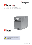
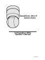
SpeedDome® Ultra IV
Camera Dome Configuration Utility
Operator’s Manual
Version 2.04
EQUIPMENT MODIFICATION CAUTION
Equipment changes or modifications not expressly approved by Sensormatic Electronics Corporation, the party
responsible for FCC compliance, could void the user's authority to operate the equipment and could create a hazardous
condition.
FCC COMPLIANCE
This equipment complies with Part 15 of the FCC rules for Class A digital devices when installed and used in accordance
with the instruction manual. Following these rules provides reasonable protection against harmful interference from
equipment operated in a commercial area. This equipment should not be installed in a residential area as it can radiate
radio frequency energy that could interfere with radio communications, a situation the user would have to fix at their own
expense.
WARRANTY DISCLAIMER
Sensormatic Electronics Corporation makes no representation or warranty of the contents of this manual and disclaims
any implied warranties of merchantability or fitness. Sensormatic Electronics Corporation reserves the right to revise this
manual and change its content without obligation to notify any person of these revisions.
LIMITED RIGHTS NOTICE
For units of the Department of Defense, all documentation and manuals were developed at private expense and no part of
it was developed using Government Funds. The restrictions governing the use and disclosure of technical data marked
with this legend are set forth in the definition of "limited rights" in paragraph (a) (15) of the clause of DFARS
252.227.7013. Unpublished - rights reserved under the Copyright Laws of the United States.
SOFTWARE LICENSE AGREEMENT
A Software License Agreement appears in Appendix B of this manual. Please read it carefully. Using the
SpeedDome Ultra IV Camera Dome Configuration Utility software indicates that you accept the terms and
conditions of this agreement.
Copyright 1999
All rights reserved.
No part of this manual may be reproduced in any form without written permission from Sensormatic® Electronics
Corporation.
Sensormatic and the Sensormatic logo are registered trademarks of Sensormatic Electronics Corporation.
Product names mentioned herein may be trademarks or registered trademarks of other companies.
PN- 8000-2612-01, Rev. C
BSL 3/99
Table of Contents
BEFORE YOU BEGIN ......................................................................................................... V
What’s In This Manual? ...................................................................................................................................vi
Text Conventions.............................................................................................................................................vi
Related Documents ........................................................................................................................................ vii
Getting Help.................................................................................................................................................... vii
CHAPTER 1: GETTING STARTED .................................................................................. 1-1
What Is the Dome Configuration Utility?....................................................................................................... 1-2
Starting the Configuration Utility ................................................................................................................... 1-2
Moving Around the Screen and Selecting Choices ...................................................................................... 1-3
Exiting the Utility ........................................................................................................................................... 1-3
Password Protection..................................................................................................................................... 1-4
Restoring Factory Settings ........................................................................................................................... 1-5
Where To Go Next........................................................................................................................................ 1-6
Keeping Records .......................................................................................................................................... 1-6
CHAPTER 2: PAN, TILT, AND ZOOM OPTIONS............................................................. 2-1
Overview of Pan, Tilt, and Zoom Settings .................................................................................................... 2-2
Setting the Automatic “Flip” Feature ............................................................................................................. 2-2
Setting the Zoom Stop Factors ..................................................................................................................... 2-3
Setting the First Zoom Stop ...................................................................................................................... 2-3
Changing the Maximum Zoom Setting ..................................................................................................... 2-4
What To Do Next .......................................................................................................................................... 2-5
CHAPTER 3: CAMERA AND LENS FUNCTIONS............................................................ 3-1
Overview of Camera and Lens Function Settings ........................................................................................ 3-2
Setting Line Lock .......................................................................................................................................... 3-2
Automatic Gain Control Settings................................................................................................................... 3-3
Setting the AGC Mode.............................................................................................................................. 3-4
Changing the AGC Manual Gain Setting .................................................................................................. 3-4
Adjusting White Balance............................................................................................................................... 3-5
Setting the Automatic White Balance Feature.......................................................................................... 3-5
Changing the Red and Blue Settings........................................................................................................ 3-6
What To Do Next ..........................................................................................................................................3-8
CHAPTER 4: ALARMS, AREAS, AND HOME SETTINGS...............................................4-1
Overview of Alarms, Areas, and Home Position Settings .............................................................................4-2
Configuring Alarm Actions.............................................................................................................................4-2
Assigning Alarm Actions ...........................................................................................................................4-3
Configuring Normal Input States ...................................................................................................................4-5
Setting Normal Input States ......................................................................................................................4-6
Setting the Home Position.........................................................................................................................4-7
Setting Area Boundaries .........................................................................................................................4-10
Programming Presets .................................................................................................................................4-11
Setting Presets ........................................................................................................................................4-12
What To Do Next ........................................................................................................................................4-13
CHAPTER 5: ON-SCREEN TEXT DISPLAY SETTINGS..................................................5-1
Overview of On-Screen Text Display Settings ..............................................................................................5-2
Displaying or Hiding Status Information ........................................................................................................5-2
Displaying or Hiding Name Information.........................................................................................................5-3
Changing the Display of All Name Information .........................................................................................5-4
Changing the Display of Selected Name Information ...............................................................................5-4
Displaying Diagnostic Tests During Reset ....................................................................................................5-6
Assigning or Changing Name Information ....................................................................................................5-7
Setting Names...........................................................................................................................................5-7
Changing Text Display Attributes ................................................................................................................5-10
What To Do Next ........................................................................................................................................5-12
CHAPTER 6: LANGUAGE AND PASSWORD SETTINGS...............................................6-1
Overview of Language and Password Settings.............................................................................................6-2
Selecting a Language....................................................................................................................................6-2
Working with Passwords ...............................................................................................................................6-4
Setting or Changing the Dome Password .................................................................................................6-4
Enabling or Disabling Password Protection ..............................................................................................6-5
What To Do Next ..........................................................................................................................................6-6
APPENDIX A: RECORDS ................................................................................................ A-1
APPENDIX B: SOFTWARE LICENSE AGREEMENT ..................................................... B-1
iv
Operator's Manual
Before You Begin
In This Preface:
•
•
•
•
What’s In This Manual?
Documentation Conventions
Related Information
Getting Help
What’s In This Manual?
This manual is organized as follows:
•
Chapter 1, Getting Started, describes how to use the SpeedDome Ultra IV Camera Dome
configuration utility.
•
Chapter 2, Pan, Tilt and Zoom Options, describes how to set the “flip” feature and zoom
stop settings for the dome.
•
Chapter 3, Camera and Lens Functions, describes how to set the line lock to prevent
vertical rolling and how to set the automatic gain control and adjust the white balance.
•
Chapter 4, Alarms, Areas and Home Settings, describes how to assign presets or patterns
and set the normal state for alarm inputs. You can specify whether or not a pattern or
preset should run after defined periods of inactivity. In addition, you can also set the
boundaries for up to 16 areas and program presets.
•
Chapter 5, On-Screen Text Display Settings, describes how to enable or disable the
display of status, name and diagnostic information associated with the camera dome. It
also provides instructions for setting or changing the names of areas, presets, patterns,
alarms, and the dome. You can also set the appearance of text displayed by the camera
dome.
•
Chapter 6, Language and Password Settings, describes how set the language for the
menus and prompts. It also describes how to set and enable a password to prevent
unauthorized use of the configuration utility.
IMPORTANT
If Portuguese is the selected language, the characters “ã” and “õ ” will not
be displayed on the screen. This is due to a limitation of the dome text
overlay chip.
•
Appendix A, Records, provides a convenient place for listing the configuration
information associated with your camera dome.
•
Appendix B, Software License Agreement, lists the terms and conditions for using this
product.
Text Conventions
This book uses text in different ways to identify different kinds of information.
Italics
vi
Used for terms specific to your system, and
text that requires emphasis, for example
Preset
Monospace
Used for menu selections or settings, for
example, On-screen Text Display
Bold
Used for names of buttons, for example,
Focus Near
Operator’s Manual
Note
Special notes are separated by ruled lines, like this.
Related Documents
Other sources provide supplemental information about your SpeedDome Ultra IV Camera
Dome. These sources serve to enhance your understanding of the product and its use.
•
•
The SpeedDome Ultra IV Camera Dome Configuration Utility Quick Reference Guide
(8000-2613-01) provides a brief overview of how to use the configuration utility.
The SpeedDome Ultra IV Camera Dome Installation and Service Guide (8000-2573-18)
provides specific information about the wiring and physical set up of the camera dome.
Getting Help
If you have a question about operation of this product, and you cannot find the answer in this
document, consult with your supervisor. If your supervisor cannot answer your question,
contact the Help Desk at 1-800-241-6678.
Before You Begin
vii
C H A P T E R
1
Getting Started
In This Chapter
•
•
•
•
•
•
•
What Is the Dome Configuration Utility?
Starting the Configuration Utility
Moving Around the Screen and Making Selections
Exiting the Utility
Password Protection
Restoring Factory Settings
Where To Go Next
What Is the Dome Configuration Utility?
The dome configuration utility provides a means to setting features for your camera dome via
a text overlay menu. You access this menu using a keystroke combination. Refer to your
keyboard or Touch Tracker operating instructions for the locations of the buttons referenced
in this document.
The utility provides settings relating to camera functions, alarms, text display, and password
protection. Some items supplement similar features that may be available through your
controller.
Starting the Configuration Utility
To start the configuration utility, do the following:
1. Select the dome that you need to configure. Refer to the controller operating instructions
for specific information.
2. Do one of the following:
•
•
If the dome is installed in a SensorNet or RS-422 operating network, press and hold Iris
Open, press and hold Focus Near or Focus Far, then press Zoom Out.
If the dome is installed in a Manchester network, turn the key switch to Prog (or disable
the system lock on the Touch Tracker), enter 66, then press Set Shot.
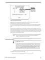
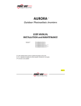
The following text appears on the monitor.
DOME CONFIGURATION MENU
PAN/TILT/ZOOM OPTIONS
CAMERA / LENS FUNCTIONS
ALARMS / AREAS / HOME
ON-SCREEN TEXT DISPLAY
LANGUAGE / PASSWORD
Highlight Bar:
Move with Tilt
control.
EXIT AND SAVE CHANGES
QUIT WITHOUT SAVING
RESET TO FACTORY SETTINGS
Figure 1-1: Dome Configuration Menu
Note
1-2
If you have password protection enabled for the configuration utility, the
Enter Password screen appears first. You must correctly enter the
password before the Dome Configuration Menu will appear. For
information about entering the password, refer to Password Protection on
page 1-4.
Operator's Manual
Moving Around the Screen and Selecting Choices
All screens in the configuration utility use the same controls to move the highlight bar around
the screen and to make selections. For combination keystrokes, press and hold each button in
sequence, then release. Refer to your controller operating instructions for the locations
of the buttons.
Note:
used.
Where no specific Focus button is listed, either Focus Near or Focus Far may be
Function
Control
Starts the configuration utility (SensorNet or
RS-422 only)
Iris Open, Focus, then
Zoom Out
Starts the configuration utility (Manchester
only)
Key switch to Prog, 66, then
Set Shot
Save changes and exits the utility from any
screen1
Iris Close, then Focus
Moves highlight bar to the previous item on
the screen
Tilt Up
Moves highlight bar to the next item on the
screen
Tilt Down
Moves highlight bar to the next position
right
Pan Right
Moves highlight bar to the next position left
Pan Left
Selects the highlighted item on the screen
Focus Far
Increases the value of the selected field or
displays the next choice for the field.
Zoom In
(Zoom Tele)
During naming, moves the cursor to the right
of the current character in the name.
Decreases the value of the selected field, or
displays the previous choice for the field.
Zoom Out
(Zoom Wide)
During naming, moves the cursor to the left
of the current character in the name.
Exiting the Utility
When you finish working with the configuration utility, you can save your changes and exit
the utility by pressing and holding Iris Close, then pressing Focus Near or Focus Far.2
1
2
This command is not supported with Manchester.
Not supported with Manchester.
Getting Started
1-3
From the Dome Configuration Menu, you have two choices for exiting the utility: Exit
and Save Changes or Quit Without Saving. Use the Tilt control to move the highlight bar
up and down on the screen.
•
If you want to keep the changes you made, move the highlight bar to Exit and Save
Changes, then press Focus Far. The utility closes.
•
If you want to exit without making changes, highlight Quit Without Saving, then press
Focus Far. The following prompt appears on the screen:
Data Not Saved. Quit Anyway?
No
Press Zoom In or Zoom Out to toggle the setting. If you want to cancel the changes, select
Yes, then press Focus Far. If you want to keep the changes, select No, then press Focus
Far. If you choose No, the Dome Configuration Menu is displayed.
Note
If areas are programmed, you cannot restore the old area boundaries by
quitting without saving changes from the Dome Configuration Menu.
Areas are the only settings that will not be restored by selecting Quit
Without Saving.
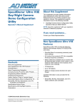
Password Protection
To prevent unauthorized users from starting the configuration utility, you can enable
password protection.
ENTER PASSWORD
PASSWORD:
A
U
o
7
B
V
p
8
C
W
q
9
D
X
r
/
Asterisks (*)
appear here with
each character
selected.
E F G H I J K L M N O P Q R S T
Y Z a b c d e f g h i j k l m n
s t u v w x y z 0 1 2 3 4 5 6
Blank space
character.
CONTINUE
CANCEL
Figure 1-2: Enter Password Screen
This will require users to enter the password before the Dome Configuration Menu will
display. The password may be from 1 to 8 characters long.
•
•
1-4
Use the Pan or Tilt control move the cursor around the character field.
Press Focus Far to enter the highlighted character.
Operator's Manual
•
Press Zoom In to move the cursor in the Password field to the right;
press Zoom Out to move the cursor in the Password field to the left.
As each character in the password is selected, asterisks (*) appear in the Password field.
When you have finished entering the password, use the Tilt control to move the highlight bar
to Continue, then press Focus Far. If the password has been correctly entered, the Dome
Configuration Menu appears. If the password was not entered correctly, the Enter
Password screen remains on the monitor.
If you do not want to start the configuration utility, use the Tilt control to move the highlight
bar to Cancel, then press Focus Far.
IMPORTANT
If you forget the password, contact technical support for instructions about
overriding the existing password.
Restoring Factory Settings
Note
Selecting Reset to Factory Settings from the Dome Configuration
Menu does not change the following settings: Camera Name, Alarm Names,
Area Names, Preset Names, Pattern Names, Area Boundaries, and Presets.
To reset names to the default settings, refer to Chapter 5, On-Screen Text
Display Settings.
Some screens provide a choice to Reset to Factory Settings. This choice applies only to
those settings currently displayed on the screen. To reset all configuration settings, choose
Reset to Factory Settings from the Dome Configuration Menu. You will see the
following prompt:
Reset to Factory Settings
No
Press Zoom In or Zoom Out to toggle the setting. If you want to restore the factory settings,
select Yes, then press Focus Far. If you do not want to restore the factory settings, select No,
then press Focus Far.
Getting Started
1-5
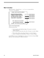
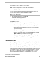
Where To Go Next
Now that you understand how to start and work with the configuration utility, you are ready
to begin changing the settings for your dome. Use the following chart to determine which
chapters you should use next.
Chapter
Topics Covered
Chapter 2: Pan, Tilt, and
Zoom Options
•
Set the “flip” feature (rotates dome 180°)
•
Set first zoom stop (16X or 24X) and
maximum zoom stop (up to 128X)
Chapter 3: Camera and Lens
Functions
•
Set line lock (prevents vertical rolling when
camera is switched)
•
Enable automatic or manual gain settings
•
Enable automatic or manual white balance
settings (red and blue values)
•
Set alarm actions (preset, pattern, or no
action)
•
Configure normal input states for alarms
(open or closed)
•
Send input states to host controller
•
Set “home” position for dome
•
Program area boundaries
•
Program presets
•
Display or hide dome status information
•
Display or hide camera, preset, pattern, area
or alarm name information
•
Display diagnostic information or firmware
version information during dome reset
•
Assign names to camera, presets, patterns,
areas, and alarms
•
Reset all names to factory defaults
•
Set text attributes (outline and translucent
characters)
•
Choose the language for the menus and
prompts
•
Set password
•
Enable or disable password feature
Chapter 4: Alarms, Areas, and
Home Settings
Chapter 5: On-Screen Text
Display Settings
Chapter 6: Language and
Password Settings
Keeping Records
Appendix A, Records, summarizes the default values for each configuration setting. In
addition, it provides space for writing information about the settings you change. Be sure to
keep records for each SpeedDome Ultra IV Camera Dome installed at your facility.
1-6
Operator's Manual
C H A P T E R
2
Pan, Tilt, and Zoom Options
In This Chapter
•
•
•
•
Overview of Pan, Tilt, and Zoom Settings
Setting the “Flip” Feature
Setting Zoom Stop Factors
What To Do Next
Overview of Pan, Tilt, and Zoom Settings
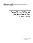
When Pan/Tilt/Zoom Options is selected from the Dome Configuration Menu, the
following screen appears:
PAN / TILT / ZOOM OPTIONS
PROPORTIONAL FLIP
1ST ZOOM STOP X
MAX TOTAL ZOOM X
OFF
24
128
Highlight Bar:
Move with Tilt
control
EXIT
RESET TO FACTORY SETTINGS
Figure 2-1: Pan / Tilt / Zoom Screen
From this screen you can, enable or disable the flip feature and set the first zoom stop and
maximum zoom settings.
•
To move the highlight bar, use the Tilt control.
•
Pressing Zoom Out or Zoom In changes value of the selected setting.
•
If you want to save your changes, move the highlight bar to Exit, then press Focus Far
to return to the Dome Configuration Menu.
•
If you want to change the settings for this screen to the factory defaults, move the
highlight bar to Reset to Factory Settings, then press Focus Far.
Setting the Automatic “Flip” Feature
The automatic (or proportional) “flip” feature allows the dome to automatically turn 180degrees when the camera tilts to its lower limit and stays in that position for a brief delay.
The duration of the delay is inversely proportional to the tilt speed.
When the dome flips (rotates), the camera starts moving upward as long as the tilt control is
kept in the down position. Once the tilt control is released, the control returns to its normal
operational mode. The flip feature is useful when you need to track someone who walks
directly beneath the dome and continues on the other side.
When the flip feature is disabled, the dome stops when the tilt down stop is reached.
To change the flip setting:
1. Select Pan/Tilt/Zoom Options from the Dome Configuration Menu.
The highlight bar appears on the Proportional Flip setting.
2-2
Operator’s Manual
2. Press Zoom Out or Zoom In to toggle the setting.
•
If you want the flip feature enabled, select On.
•
If you want the flip feature disabled, select Off.
The default setting is Off.
3. Do one of the following:
•
•
•
If you want to make changes to the zoom stop settings, continue with Setting the
Zoom Stop Factors on page 2-3.
If you are finished making changes, press and hold Iris Close, then press Focus
Near or Focus Far to save your changes and exit the utility.1
If you want to make changes to other settings, use the Tilt control to move the
highlight bar to Exit, then press Focus Far. The Dome Configuration Menu
appears. Continue with What To Do Next on page 2-5.
Setting the Zoom Stop Factors
Zoom stop factors define how to partition the zoom function.
For example, you set the first zoom stop to 16X and the maximum zoom to 112X. If the
current zoom factor is less than 16X, pressing Zoom In continuously causes the zoom to stop
at 16X. If the current zoom factor is 16X (or greater), pressing Zoom In continuously causes
the zoom to stop at 112X. The second zoom stop will be in effect until the zoom factor is
reduced to less than the first zoom stop factor (16X) and the zoom button is released for one
second or longer.
The margin of error for the zoom stop factor is ± 2X for the dome.
Setting the First Zoom Stop
1. Select Pan/Tilt/Zoom Options from the Dome Configuration Menu.
2. Use the Tilt control to move the highlight bar to the 1st Zoom Stop X setting.
3. Press Zoom Out or Zoom In to change the setting.
•
If you want the first zoom stop to be 16X magnification, select 16.
•
If you want the first zoom stop to be 24X magnification, select 24.
The default setting is 24X.
4. Do one of the following:
•
•
•
1
If you want to change the maximum zoom setting, continue with Changing the
Maximum Zoom Setting on page 2-4.
If you want to make changes to the flip setting, refer to Setting the Automatic
“Flip” Feature on page 2-2.
If you are finished making changes, press and hold Iris Close, then press Focus
Near or Focus Far to save your changes and exit the utility.2
This command is not supported with Manchester.
Pan, Tilt, and Zoom Options
2-3
•
If you want to make changes to other settings, use the Tilt control to move the
highlight bar to Exit, then press Focus Far. The Dome Configuration Menu
appears. Continue with What To Do Next on page 2-5.
Changing the Maximum Zoom Setting
1. Select Pan/Tilt/Zoom Options from the Dome Configuration Menu.
2. Use the Tilt control to move the highlight bar to the Max Total Zoom X setting.
The values for the setting are: 32X, 48X, 64X, 80X, 96X, 112X and 128X magnification.
The default setting is 64X.
3. Press Zoom Out to decrease the value of the setting.
Press Zoom In to increase the value of the setting.
4. Do one of the following:
2
•
If you want to make changes to the flip setting, refer to Setting the Automatic
“Flip” Feature on page 2-2.
•
If you want to make changes to the first zoom stop, refer to Setting the First
Zoom Stop on page 2-3.
•
If you are finished making changes, press and hold Iris Close, then press Focus
Near or Focus Far to save your changes and exit the utility.
•
If you want to make changes to other settings, use the Tilt control to move the
highlight bar to Exit, then press Focus Far. The Dome Configuration Menu
appears. Continue with What To Do Next on page 2-5.
This command is not supported with Manchester.
2-4
Operator’s Manual
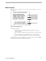
What To Do Next
When you select Exit from the Pan/Tilt/Zoom Options screen, the Dome Configuration
Menu appears.
DOME CONFIGURATION MENU
PAN/TILT/ZOOM OPTIONS
CAMERA / LENS FUNCTIONS
ALARMS / AREAS / HOME
ON-SCREEN TEXT DISPLAY
LANGUAGE / PASSWORD
EXIT AND SAVE CHANGES
QUIT WITHOUT SAVING
RESET TO FACTORY SETTINGS
Covered in Chapter 2
Covered in Chapter 3
Covered in Chapter 4
Covered in Chapter 5
Covered in Chapter 6
Covered in Chapter 1
Figure 2-2: Dome Configuration Menu
From this screen you can:
•
•
•
•
Select an option to make additional changes. These topics are covered in
chapters 2 through 6.
Save the changes you made and exit the utility. This topic is covered in Chapter
1.
Exit the utility without saving changes. This topic is covered in Chapter 1.
Restore all settings to the factory defaults. This topic is covered in Chapter 1.
Use the Tilt control to move the highlight bar to selection you want to use, then press Focus
Far. Refer to the related chapter for additional information.
Pan, Tilt, and Zoom Options
2-5
C H A P T E R
3
Camera and Lens Functions
In This Chapter
•
•
•
•
•
Overview of Camera and Lens Settings
Setting Line Lock
Automatic Gain Control Settings
Adjusting White Balance
What To Do Next
Overview of Camera and Lens Function Settings
When Camera / Lens Functions is selected from the Dome Configuration Menu, the
following screen appears:
CAMERA / LENS FUNCTIONS
LINE LOCK
AGC MODE
AGC GAIN
AUTO WHITE BAL
RED WHITE BAL
BLUE WHITE BAL
OFF
ON
112
ON
128
1023
Highlight Bar:
Move with Tilt
control.
EXIT
RESET TO FACTORY SETTINGS
Figure 3-1: Camera and Lens Functions Screen
From this screen you can set the line lock to prevent video rolling, set automatic gain control
to either automatic or manual, and adjust the white balance settings.
•
To move the highlight bar, use the Tilt control.
•
Pressing Zoom Out or Zoom In changes value of the selected setting.
•
When you finish making changes, move the highlight bar to Exit, then press Focus Far
to return to the Dome Configuration Menu.
•
If you want to change the settings for this screen to the factory defaults, move the
highlight bar to Reset to Factory Settings, then press Focus Far.
Setting Line Lock
Use the Line Lock setting to prevent vertical rolling or adjust the appearance of overlay text
on color monitors.
If you experience problems with vertical video rolling when switching multiple cameras to a
single monitor, enabling the line lock will phase lock the video with the AC power line. All
cameras connected to the same power supply will be synchronized. This synchronization
prevents the video from rolling vertically when cameras are switched.
To change the line lock setting:
1. Select Camera / Lens Functions from the Dome Configuration Menu.
The highlight bar appears on the Line Lock setting.
2. Press Zoom Out or Zoom In to change the setting.
3-2
Operator’s Manual
•
•
If you want to enable the line lock, select On.
If you want to disable the line lock, select Off.
The default setting is On.
3. Do one of the following:
•
If you want to make changes to the automatic gain control settings, refer to
Automatic Gain Control Settings on page 3-3.
•
If you want to make changes to the white balance settings, refer to Adjusting
White Balance on page 3-5.
•
If you are finished making changes, press and hold Iris Close, then press Focus
Near or Focus Far to save your changes and exit the utility.1
•
If you want to make changes to other settings, use the Tilt control to move the
highlight bar to Exit, then press Focus Far. The Dome Configuration Menu
appears. Continue with What To Do Next on page 3-8.
Note
The change in line lock setting is not immediate. The dome must reinitialize
(reset) for the change in the line lock setting to take place. When you exit the
configuration utility, you will receive the following prompt:
DOME MUST RESET TO
CHANGE LINE LOCK MODE.
RESET DOME NOW?
NO
Press Zoom In or Zoom Out to toggle the selection. If you do not want to
reinitialize the dome, select No, then press Focus Far. If you want to
reinitialize the dome, select Yes, then press Focus Far.
The default selection is No.
Automatic Gain Control Settings
Automatic Gain Control (AGC) allows for the amplification of the video signal in scenes
with minimal ambient light. Many low-light scenes result in picture noise. As gain is
increased, the picture noise is also amplified.
When AGC is enabled, the the gain setting value is based on feedback from the camera.
When AGC is disabled, the camera uses the manual gain setting value. The trade-off between
picture level and noise may be adjusted when AGC is disabled.
1
This command is not supported with Manchester.
Camera and Lens Functions
3-3
Setting the AGC Mode
1. Select Camera / Lens Functions from the Dome Configuration Menu.
2. Use the Tilt control to move the highlight bar to the AGC Mode setting.
3. Press Zoom Out or Zoom In to change the setting.
•
•
If you want the AGC to be automatic, select On.
If you want the AGC to be manual, select Off. Then continue with Changing the
AGC Manual Gain Setting on page 3-4.
The default setting is On.
4. Do one of the following:
•
If you want to make changes to the line lock setting, refer to Setting Line Lock on
page 3-2.
•
If you want to make changes to the white balance settings, refer to Adjusting
White Balance on page 3-5.
•
If you are finished making changes, press and hold Iris Close, then press Focus
Near or Focus Far to save your changes and exit the utility.2
•
If you want to make changes to other settings, use the Tilt control to move the
highlight bar to Exit, then press Focus Far. The Dome Configuration Menu
appears. Continue with What To Do Next on page 3-8.
Changing the AGC Manual Gain Setting
Note
AGC Mode must be set to Off to make changes to this setting.
1. Select Camera / Lens Functions from the Dome Configuration Menu.
2. Use the Tilt control to move the highlight bar to the AGC Gain setting.
3. Press Zoom Out to decrease value of the setting.
Press Zoom In to increase the value of the setting.
The values for the setting range from 0 to 1128.
4. Do one of the following:
2
•
If you want to make changes to the line lock setting, refer to Setting Line Lock on
page 3-2.
•
If you need to make adjustments in the white balance, refer to Adjusting White
Balance on page 3-5.
•
If you are finished making changes, press and hold Iris Close, then press Focus
Near or Focus Far to save your changes and exit the utility.3
This command is not supported with Manchester.
3-4
Operator’s Manual
•
If you want to make changes to other settings, use the Tilt control to move the
highlight bar to Exit, then press Focus Far. The Dome Configuration Menu
appears. Continue with What To Do Next on page 3-8.
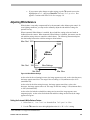
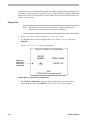
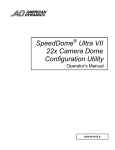
Adjusting White Balance
White balance is normally compensated for by the automatic white balance gain control. In
some lighting conditions, you may need to manually adjust the red and blue settings for
optimal viewing.
When Automatic White Balance is enabled, the red and blue setting values are based on
feedback from the camera. When Automatic White Balance is disabled, the camera uses the
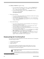
red and blue setting values to control the white balance. The following illustration depicts
the relationship between the red blue settings to white balance.
Max. Red 1023
Red Settings
Appears
Magenta
(purple)
Min. Red
128
Appears
Green
128
Min. Blue
White
Balance
Blue Settings
1023
Max. Blue
Figure 3-2: White Balance Settings
As the value for the red setting increases, the image appears more red; as the value decreases,
the image appears more blue. The range of the red setting is 128 (minimum red) to 1023
(maximum red).
As the value for the blue setting increases, the image appears more blue; as the value
decreases, the image appears more red. The range for the blue setting is 128 (minimum blue)
to 1023 (maximum blue).
As the values for both the red and blue settings are increased, the image appears more
magenta (purple). As the values for both the red and blue settings are decreased, the image
appears more green.
Setting the Automatic White Balance Feature
1. Select Camera / Lens Functions from the Dome Configuration Menu.
2. Use the Tilt control to move the highlight bar to the Auto White Bal setting.
3
This command is not supported with Manchester.
Camera and Lens Functions
3-5
3. Press Zoom Out or Zoom In to change the setting.
•
If you want the white balance to be automatic, select On.
•
If you want manually adjust the red or blue settings, select Off. Then continue
with Changing the Red and Blue Settings on page 3-6.
The default setting is On.
4. Do one of the following:
•
If you want to make changes to the line lock setting, refer to Setting Line Lock on
page 3-2.
•
If you want to make changes to the automatic gain control settings, refer to
Automatic Gain Control Settings on page 3-3.
•
If you are finished making changes, press and hold Iris Close, then press Focus
Near or Focus Far to save your changes and exit the utility.4
•
If you want to make changes to other settings, use the Tilt control to move the
highlight bar to Exit, then press Focus Far. The Dome Configuration Menu
appears. Continue with What To Do Next on page 3-8.
Changing the Red and Blue Settings
Note
Auto White Bal must be set to Off to make changes to this setting.
1. Select Camera / Lens Functions from the Dome Configuration Menu.
2. If you want to make changes to the red setting, use the Tilt control to move the highlight
bar to Red White Bal, then continue with step 3.
If you want to make changes to the blue setting, continue with step 4.
3. Press Zoom In or Zoom Out to adjust the setting. The values range from 128 to 1023.
•
•
Press Zoom In to increase the value of the setting.
Press Zoom Out to decrease value of the setting.
There is no default value for the red setting.
4. Do one of the following:
•
•
If you want to make changes to the blue setting, use the Tilt control to move the
highlight bar to Blue White Bal, then continue with step 5.
If you are finished making changes, continue with step 6.
5. Press Zoom In or Zoom Out to adjust the setting. The values range from 128 to 1023.
•
4
Press Zoom In to increase the value of the setting.
This command is not supported with Manchester.
3-6
Operator’s Manual
•
Press Zoom Out to decrease value of the setting.
There is no default value for the blue setting.
6. Do one of the following:
•
•
•
•
5
If you want to make changes to the line lock setting, refer to Setting Line Lock on
page 3-2.
If you need to make adjustments in the automatic gain control, refer to Automatic
Gain Control Settings on page 3-3.
If you are finished making changes, press and hold Iris Close, then press Focus
Near or Focus Far to save your changes and exit the utility.5
If you want to make changes to other settings, use the Tilt control to move the
highlight bar to Exit, then press Focus Far. The Dome Configuration Menu
appears. Continue with What To Do Next on page 3-8.
This command is not supported with Manchester.
Camera and Lens Functions
3-7
What To Do Next
When you select Exit from the Camera / Lens Functions screen, the Dome
Configuration Menu appears.
DOME CONFIGURATION MENU
PAN/TILT/ZOOM OPTIONS
CAMERA / LENS FUNCTIONS
ALARMS / AREAS / HOME
ON-SCREEN TEXT DISPLAY
LANGUAGE / PASSWORD
EXIT AND SAVE CHANGES
QUIT WITHOUT SAVING
RESET TO FACTORY SETTINGS
Covered in Chapter 2
Covered in Chapter 3
Covered in Chapter 4
Covered in Chapter 5
Covered in Chapter 6
Covered in Chapter 1
Figure 3-3: Dome Configuration Menu
From this screen you can:
•
•
•
•
Select an option to make additional changes. These topics are covered in
chapters 2 through 6.
Save the changes you made and exit the utility. This topic is covered in Chapter
1.
Exit the utility without saving changes. This topic is covered in Chapter 1.
Restore all settings to the factory defaults. This topic is covered in Chapter 1.
Use the Tilt control to move the highlight bar to selection you want to use, then press Focus
Far. Refer to the related chapter for additional information.
3-8
Operator’s Manual
C H A P T E R
4
Alarms, Areas, and Home Settings
In This Chapter
•
•
•
•
•
•
•
Overview of Alarms, Areas, and Home Position Settings
Configuring Alarm Actions
Configuring Normal Input States
Assigning the Dome’s Home Position
Programming Area Boundaries
Programming Presets
What To Do Next
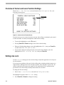
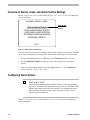
Overview of Alarms, Areas, and Home Position Settings
When Alarms/Areas/Home is selected from the Dome Configuration Menu, the following
screen is displayed:
ALARMS / AREAS / HOME
SET ALARM ACTIONS
CONFIGURE NORMAL STATES
CONFIGURE HOME POSITION
PROGRAM AREA BOUNDARIES
PROGRAM PRESETS
Highlight Bar:
Move with Tilt
control.
EXIT
Figure 4-1: Alarm / Areas / Home Screen
From this menu you can choose to configure alarm actions, configure normal states for alarm
inputs, set area boundaries, program presets, and assign the “home position” for the dome.
•
To move the highlight bar, use the Tilt control. Press Focus Far to make a selection.
•
Pressing Zoom Out or Zoom In changes the value of the settings on the subsequent
screens.
•
When you finish making changes, move the highlight bar to Exit. Press Focus Far to
return to the Dome Configuration Menu.
Configuring Alarm Actions
IMPORTANT
When operating on Manchester networks, the dome can be programmed to
respond to any of the four available alarm inputs. However, the dome cannot
transmit alarm input states to the host controller. If transmitting the alarm
state to the host controller is required, the alarm device must be wired
directly to the host controller.
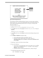
When Set Alarm Actions is selected from Alarms/Areas/Home screen, the following
screen is displayed:
4-2
Operator’s Manual
SET ALARM ACTIONS
INTERNAL ALARMS
INPUT NO.
ACTION
NO ACTION
1
PRESET 96
2
PATTERN 3
3
NO ACTION
4
SEND INPUTS TO HOST?
Highlight Bar:
Move up / down
with Tilt control.
Move right / left
with Pan control.
YES
EXIT
Figure 4-2: Set Alarm Actions Screen
Alarms can be processed internally by the dome, externally by the controller, or both.
Internal alarms are configured by setting a preset or pattern.
A preset is a programmed video scene, based on a specific pan, tilt, zoom, and focus settings.
A pattern is a series of pan, tilt, zoom and focus movements from a single programmable
dome.
For each of the four alarm inputs, you can choose to display a preset or pattern whenever the
alarm's input state changes from normal to abnormal. Or you may choose to have no internal
alarm associated with the input. You may also choose to send changes in the input state to the
host controller. If the changes in input state are sent to the host, the host actions have higher
priority than the associated dome actions.
Note
An active internal alarm only resets when the input state changes to
“normal.” A manual reset is not available.
Assigning Alarm Actions
IMPORTANT
Certain controllers allow the alarm actions for domes to be specified at the
controller. These controllers include VM16 Plus, VM32, VM96, ADTT16,
AD32, AD matrices with AD2083-02A code units, or AD168 with CCM or
AD2083-02A. Do not use both the dome configuration utility and the
controller to assign the alarm actions for the same input. Use only the
dome configuration utility or the controller to the assign the alarm actions.
To configure alarm actions, do the following:
1. Select Alarms/Areas/Home from the Dome Configuration Menu.
Alarms, Areas and Home Settings
4-3
The highlight bar appears on the Set Alarm Actions option. Press Focus Far to select.
2. Use the Tilt control to move the highlight bar to the appropriate alarm input.
3. Press Zoom In or Zoom Out to change the setting.
•
•
•
If you want the action to be a preset, choose Preset then continue with step 4.
If you want the action to be a pattern, choose Pattern then continue with step 4.
If you do not want a special action for this input, choose No Action then
continue with step 5.
The default setting is No Action.
4. Use Pan Right to move the highlight bar to the Action Number field, then press Zoom In
or Zoom Out to change the setting.
•
•
If the alarm action is a preset, select the number from 1 through 96 for the preset
you want to assign.
If the preset has not been programmed, preset programming automatically starts.
Refer to Programming Presets on page 4-11.
If the preset has been programmed, continue with step 5.
If the alarm action is a pattern, select the number (1 through 3) for the pattern
you want to assign. Then continue with step 5.
5. If you need to make additional changes to the alarm actions for this dome, repeat steps 3
through 5. When finished, continue with step 6.
6. Use the Tilt control to move the highlight bar to Send Inputs to Host?
7. Press Zoom In or Zoom Out to change the setting.
•
If you want changes in the input states to be forwarded to the host controller,
choose Yes.1 Continue with step 8.
•
If you do not want changes in the input states to be forwarded to the host
controller, choose No. Continue with step 8.
The default setting is Yes.
8. Use the Tilt control to move the highlight bar to Exit. Press Focus Far to return to the
Alarm/Areas/Home screen, then continue with step 9.
9. When the Alarm/Areas/Home screen appears, do one of the following:
•
•
•
•
1
If you want to configure the input states, continue with Configuring Normal
Input States on page 4-5.
If you want to set the “home” position, continue with Assigning the Dome’s
Home Position on page 4-7.
If you want to define areas, continue with Programming Area Boundaries on
page 4-9.
If you want to define presets, continue with Programming Presets on page 4-11.
This setting does not apply to Manchester.
4-4
Operator’s Manual
•
•
If you are finished making changes, press and hold Iris Close, then press Focus
Near or Focus Far to save your changes and exit the utility.2
If you want to make changes to other settings, use the Tilt control to move the
highlight bar to Exit, then press Focus Far. The Dome Configuration Menu
appears. Continue with What To Do Next on page 4-13.
Configuring Normal Input States
IMPORTANT
Certain controllers allow the normal input states for domes to be specified at
the controller. These controllers include VM96, AD matrices with AD208302A code units or AD168 matrix with AD168CCM or AD2083-02A code
unit. Do not use both the dome configuration utility and the controller to
assign the normal input states. Use only the dome configuration utility or
the controller to the assign the normal input states.
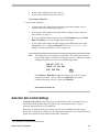
When Configure Normal States is selected from the Alarm/Areas/Home screen, the
following is displayed:
CONFIGURE NORMAL STATES
INPUT NO.
NORMAL STATE
OPEN
OPEN
CLOSED
OPEN
1
2
3
4
Highlight Bar:
Move with Tilt
control.
EXIT
Figure Chapter 4 -3: Configure Normal States Screen
Use this screen to assign open or closed as the normal state for the dome inputs. When an
input state changes from normal to abnormal and an internal alarm action is associated with
the input, the alarm is triggered. The normal state is used by both internal alarms and
controller defined alarms.
2
This command is not supported with Manchester.
Alarms, Areas and Home Settings
4-5
Setting Normal Input States
IMPORTANT
When operating on Manchester networks, the dome can be programmed to
respond to any of the four available alarm inputs. However, the alarm input
states cannot be transmitted to the host controller. If transmitting the alarm
state to the host controller is required, the alarm device must be wired
directly to the host controller.
To set the normal input states, do the following:
1. Select Alarms/Areas/Home from the Dome Configuration Menu.
2. Use the Tilt control to move the highlight bar to Configure Normal States, then press
Focus Far.
3. Use the Tilt control to move the highlight bar to the appropriate input line.
IMPORTANT
In most cases, the normal input state for a dome's input should match the
contact type of the connected switch. For example, assigning a normal input
state of “closed” when the contact type for the switch is “open” triggers an
internally-defined dome alarm when the dome input changes from closed to
open.
4. Press Zoom In or Zoom Out to toggle the setting.
•
•
If the normal input state for the input is open, select Open.
If the normal input state for the input is closed, select Closed.
The default setting is Open.
5. Repeat steps 3 and 4 for each input you need to change. When finished, continue with
step 6.
6. Use the Tilt control to move the highlight bar to Exit. Press Focus Far to return to the
Alarms/Areas/Home screen.
7. When the Alarms/Areas/Home screen appears, do one of the following:
4-6
•
If you want to configure the alarm actions, continue with Configuring Alarm
Actions on page 4-2.
•
If you want to set the “home” position, continue with Assigning the Dome’s
Home Position on page 4-7.
Operator’s Manual
•
If you want to define areas, continue with Programming Area Boundaries on
page 4-9.
•
If you want to define presets, continue with Programming Presets on page 4-11.
•
If you are finished making changes, press and hold Iris Close, then press Focus
Near or Focus Far to save your changes and exit the utility.3
•
If you want to make changes to other settings, use the Tilt control to move the
highlight bar to Exit, then press Focus Far. The Dome Configuration Menu
appears. Continue with What To Do Next on page 4-13.
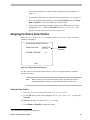
Assigning the Dome’s Home Position
When Configure Home Position is selected from the Alarms/Areas/Home screen, the
following is displayed:
CONFIGURE HOME POSITION
HOME POSITION
RETURN TIME MINS
PRESET 96
Highlight Bar:
Move with Pan/
Tilt control.
10
EXIT
Figure 4-4: Configure Home Position Screen
Use this screen if you want the dome return to a preset or run a pattern after a specified
period of inactivity.
Note
When a pattern is selected as the home position, the pattern runs until it
stopped manually by issuing a camera command such as tilt or focus.
Setting the Home Position
1. Select Alarms/Areas/Home from the Dome Configuration Menu.
2. Use the Tilt control to move the highlight bar to Configure Home Position, then press
Focus Far.
The highlight bar appears on the Home Position setting.
3. Press Zoom In or Zoom Out to change the setting.
3
This command is not supported with Manchester.
Alarms, Areas and Home Settings
4-7
•
•
•
If you want the home position to be a preset, select Preset, then continue with
step 4.
If you want the home position to be a pattern, select Pattern, then continue with
step 4.
If you do not want to set a home position, select No Action, then continue with
step 6.
The default setting is No Action.
4. Use Pan Right to move the highlight bar to the Number field, then press Zoom In or Zoom
Out to change the setting.
•
If the home position is a preset, select the number from 1 through 96 (1 through
64 for Manchester) for the preset you want to assign.
If the preset has not been programmed, preset programming automatically starts.
Refer to Programming Presets on page 4-11.
If the preset has been programmed, continue with step 5.
•
If the home position is a pattern, the select the number from 1 through 3 for the
pattern you want to assign. Continue with step 5.
5. Use the Tilt control to move the highlight bar to Return Time Mins. Press Zoom Out or
Zoom In to set the amount of time that the dome must remain inactive before returning to
the home position.
The range for the setting is 1 to 60 minutes.
The default setting is 10 minutes.
6. Use the Tilt control to move the highlight bar to Exit. Press Focus Far to return to the
Alarms/Areas/Home screen. Continue with step 7.
7. When the Alarms/Areas/Home screen appears, do one of the following:
•
•
•
•
•
•
4
If you want to configure the alarm actions, continue with Configuring Alarm
Actions on page 4-2.
If you want to configure the input states, continue with Configuring Normal
Input States on page 4-5.
If you want to define areas, continue with Programming Area Boundaries on
page 4-9.
If you want to define presets, continue with Programming Presets on page 4-11.
If you are finished making changes, press and hold Iris Close, then press Focus
Near or Focus Far to save your changes and exit the utility.4
If you want to make changes to other settings, use the Tilt control to move the
highlight bar to Exit, then press Focus Far. The Dome Configuration Menu
appears. Continue with What To Do Next on page 4-13.
This command is not supported with Manchester.
4-8
Operator’s Manual
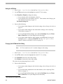
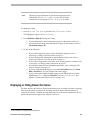
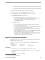
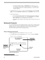
Programming Area Boundaries
Areas are programmed start and end points of a camera's field of view. Each area is a part of
a circular viewing area that extends around the dome. The areas can be different sizes, as
shown in the following illustration:
Start Area 1/
End Area 8
When zoomed in,
areas appear to be
smaller than when
zoomed out.
Area 1
Area 8
Black circle
represents
the dome.
Area 7
Area 6
Area 5
Area 2
Area 4
Area 3
Figure 4-5: An example of areas
The end point of one area is the starting point for the next area. The end point of the last area
cannot go past the starting point of the first area. If your controller supports areas, these are
separate from the areas you can program with the dome. You should not use both the
controller and the configuration utility to define areas.
The zoom setting also affects how large areas appear. When you zoom in to an area, the area
may appear to be small. When you pan the dome, area boundaries may appear to be close.
However, if you zoom out, the area appears to be larger. When you pan the dome, the area
boundaries appear further apart. With this in mind, it will be easier to establish area
boundaries if the zoom factor is small than if the zoom factor is large.
When Program Area Boundaries is selected from the Alarms/Areas/Home screen, the
following appears:
Alarms, Areas and Home Settings
4-9
PROGRAM AREA BOUNDARIES
PAN to start of BOUND
1
Displays the
number of the
area being set.
PAN RIGHT ONLY
ZOOM to mark BOUNDARY
FOCUS quits w/o changing
Figure 4-6: Program Area Boundaries Screen
The dome supports from 2 to 16 areas.
Message appears
when screen is
first displayed.
After first
boundary is set,
Focus saves and
exits.
IMPORTANT
If areas are programmed, you cannot restore the old boundaries by selecting
Quit Without Saving from the Dome Configuration Menu. Be aware of
this limitation if you begin to make changes to the boundaries and change
your mind.
Setting Area Boundaries
Note
When areas are programmed, each area is assigned a default name.
Instructions for assigning new names appear in Chapter 5.
1. Select Alarms/Areas/Home from the Dome Configuration Menu.
2. Use the Tilt control to move the highlight bar to Programming Area Boundaries, then
press Focus Far.
The Program Area Boundaries screen appears:
3. Use the Pan control to position the camera at the starting point of the first area, then
press Zoom In or Zoom Out.
4. Use the Pan Right control to move the camera to the right until the ending point of the
area is seen. If you attempt to pan left, the error message in the note below appears.
5. Press Zoom In or Zoom Out to set the end point of the area.
The area number automatically advances.
4-10
Operator’s Manual
6. Repeat steps 4 and 5 for each area you want to establish.
Note: You will see the following error message under certain conditions:
Error programming areas
Focus Far to continue.
•
•
If you attempt to program a boundary that passes the starting point of the first area
If you move the camera left after establishing the first boundary
Return to step 1 and start again.
7. When the last area boundary is set, press Focus Far.
The following confirmation message appears:
Areas saved successfully
Focus Far to continue.
Press Focus Far to continue.
8. When the Alarms/Areas/Home screen appears, do one of the following:
•
If you want to configure the alarm actions, continue with Configuring Alarm
Actions on page 4-2.
•
If you want to configure the input states, continue with Configuring Normal
Input States on page 4-5.
•
If you want to set the “home” position, continue with Assigning the Dome’s
Home Position on page 4-7.
•
If you are finished making changes, press and hold Iris Close, then press Focus
Near or Focus Far to save your changes and exit the utility.5
•
If you want to make changes to other settings, use the Tilt control to move the
highlight bar to Exit, then press Focus Far. The Dome Configuration Menu
appears. Continue with What To Do Next found on page 4-13.
Programming Presets
A preset is a programmed video scene with automatic pan, tilt, zoom, focus and iris settings.
Presets may be assigned to alarm actions or as the “home” position for the dome. Up to 96
presets whose positions are saved in the domes firmware may be programmed. Domes
installed in SensorNet or RS-422 networks support up to 96 presets. Domes installed in
Manchester networks support up to 64 presets. If you attempt to program a preset numbered
higher than 64 in a Manchester network, the controller beeps.
VM96 and AD matrices installed as RS-422 and SensorNet networks support “virtual” views.
This means that the pan, tilt, zoom, focus, and iris settings are stored within the controller,
not the dome. You cannot use the views that you define on those systems as the home
position or an alarm action. You must use the presets programmed using this utility.
5
This command is not supported with Manchester.
Alarms, Areas and Home Settings
4-11
AD168 matrices with an AD168CCM control code module support Manchester, RS-422, and
SensorNet networks and provide 64 virtual views. All other AD matrices support Manchester
and 64 dome presets or, through the use of an AD2083-02A code unit, RS-422 networks and
provide 16 virtual views.
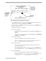
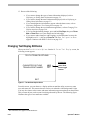
Setting Presets
Note
When presets are programmed, each preset is assigned a default name.
Instructions for assigning new names appear in Chapter 5.
1. Select Alarms/Areas/Home from the Dome Configuration Menu.
2. Use the Tilt control to move the highlight bar to Programming Presets, then press
Focus Far.
The Select Preset to Program screen appears:
SELECT PRESET TO PROGRAM
Displays the
number of the
Preset being
programmed.
PRESET
NUMBER
PRESET NAME
96
PRESET 96
EXIT
FOCUS FAR to program preset
Figure Chapter 4 -7: Select Preset to Program screen
3. Press Zoom In or Zoom Out to change the number until the preset that you want to
program appears, then press Focus Far. The Program Preset screen appears.
4-12
Operator’s Manual
PROGRAM PRESET
PRESET 96
Position camera with PAN,
TILT, ZOOM, and IRIS
FOCUS FAR to save and exit
EXIT
Figure 4-8: Program Preset screen
4. Use the Pan and Tilt controls to move the camera until you see the scene you want to use
as the preset. Adjust the zoom and iris settings as necessary. Press Focus Far to save the
preset.
5. Repeat steps 3 and 4 for each preset you want to program. When finished, use the Tilt
control to move the highlight bar to Exit, then press Focus Far.
6. When the Alarms/Areas/Home screen appears, do one of the following:
•
If you want to configure the alarm actions, continue with Configuring Alarm
Actions on page 4-2.
•
If you want to configure the input states, continue with Configuring Normal
Input States on page 4-5.
•
If you want to set the “home” position, continue with Assigning the Dome’s
Home Position on page 4-7.
•
If you want to set areas, continue with Programming Area Boundaries on page
4-9.
•
If you are finished making changes, press and hold Iris Close, then press Focus
Near or Focus Far to save your changes and exit the utility.6
•
If you want to make changes to other settings, use the Tilt control to move the
highlight bar to Exit, then press Focus Far. The Dome Configuration Menu
appears. Continue with What To Do Next found on page 4-13.
What To Do Next
When you select Exit from the Alarms/Areas/Home screen, the Dome Configuration
Menu appears.
6
This command is not supported with Manchester.
Alarms, Areas and Home Settings
4-13
DOME CONFIGURATION MENU
PAN/TILT/ZOOM OPTIONS
CAMERA / LENS FUNCTIONS
ALARMS / AREAS / HOME
ON-SCREEN TEXT DISPLAY
LANGUAGE / PASSWORD
EXIT AND SAVE CHANGES
QUIT WITHOUT SAVING
RESET TO FACTORY SETTINGS
Covered in Chapter 2
Covered in Chapter 3
Covered in Chapter 4
Covered in Chapter 5
Covered in Chapter 6
Covered in Chapter 1
Figure 4-9: Dome Configuration Menu
From this screen you can:
•
•
•
•
Select an option to make additional changes. These topics are covered in
chapters 2 through 6.
Save the changes you made and exit the utility. This topic is covered in
Chapter 1.
Exit the utility without saving changes. This topic is covered in Chapter 1.
Restore all settings to the factory defaults. This topic is covered in Chapter 1.
Use the Tilt control to move the highlight bar to the selection you want to use, then press
Focus Far. Refer to the related chapter for additional information.
4-14
Operator’s Manual
C H A P T E R
5
On-Screen Text Display Settings
In This Chapter
•
•
•
•
•
•
•
Overview of On-Screen Text Display Settings
Displaying or Hiding Status Information
Displaying or Hiding Name Information
Assigning or Changing Name Information
Displaying Diagnostic Tests During Reset
Changing Text Display Attributes
What To Do Next
Overview of On-Screen Text Display Settings
When On-Screen Text Display is selected from the Dome Configuration Menu, the
following screen is displayed:
ON-SCREEN TEXT DISPLAY
STATUS DISPLAY
OFF
DISABLE ALL NAMES?
NO
NAME CONFIGURATION MENU
TEXT ATTRIBUTE OPTIONS
Highlight Bar:
Move with Tilt
control
EXIT
Figure 5-1: On-Screen Text Display
From this screen you can choose to display status information about the dome, choose to
enable or disable the display of all name information, and choose to display diagnostic
information after a dome reset. You can start the Name Configuration Menu and the Text
Attribute Options screens.
•
To move the highlight bar, use the Tilt control.
•
Pressing Zoom Out or Zoom In changes value of the selected setting.
•
When you finish making changes, move the highlight bar to Exit, then press Focus Far
to return to the Dome Configuration Menu.
Displaying or Hiding Status Information
You can choose to display the status of the zoom setting, auto focus, and auto iris. This
information will appear in the upper left corner of the monitor. The information only appears
when there is a change in the status of any item and remains on the screen for 5 seconds. If
“D” appears next to the zoom factor, the digital zoom is active (zooms greater than 16X).
ZOOM X18D
AUTO IRIS ON/OFF
AUTO FOCUS ON/OFF
Figure 5-2: Example of Zoom, Auto Focus and Auto Iris Status Information
5-2
Operator’s Manual
Displaying status information is separate from displaying name
information. If Disable All Names? is set to Yes, the status
information will still appear if Status Display is set to On.
Note
To change the setting:
1. Select On-Screen Text Display from the Dome Configuration Menu.
The highlight bar appears on Status Display.
2. Press Zoom Out or Zoom In to change the setting.
•
•
If you want the dome status information to appear on the monitor, choose On.
If you do not want dome status information to appear on the monitor, select Off.
The default setting is Off.
3. Do one of the following:
•
•
•
•
•
•
If you want to change the types of name information displayed, refer to
Displaying or Hiding Name Information on page 5-3.
If you want diagnostic information to appear when the dome resets, refer to
Displaying Diagnostic Tests During Reset on page 5-6.
If you want to assign names to the dome, areas, presets, patterns, or alarms, refer
to Assigning or Changing Name Information on page 5-7.
If you want to change the text information appearance, refer to Changing Text
Display Attributes on page 5-10.
If you are finished making changes, press and hold Iris Close, then press Focus
Near or Focus Far to save your changes and exit the utility.1
If you want to make changes to other settings, use the Tilt control to move the
highlight bar to Exit, then press Focus Far. The Dome Configuration Menu
appears. Continue with What To Do Next on page 5-12.
Displaying or Hiding Name Information
The dome provides the ability to display the dome name, the area where the dome is pointing,
the name of the preset or pattern that is running, and alarm names. When the display of
camera or area names is enabled, the information appears on the screen continuously. Preset,
pattern, and alarm names appear only while they are active.
1
This command is not supported with Manchester.
On-Screen Text Display Settings
5-3
CAMERA NAME
PATTERN/PRESET NAME
ALARM NAME
AREA NAME
Figure 5-3: Display Locations for Name Information
You may choose to disable displaying all name information, or you may choose to display
selected or all name information.
Changing the Display of All Name Information
1. Select On-Screen Text Display from the Dome Configuration Menu.
2. Use the Tilt control to move the highlight bar to Disable All Names?
3. Press Zoom Out or Zoom In to change the setting.
•
•
If you want to disable the appearance of all name information, select Yes.
If you want all or some name information to appear on the monitor, select No.
Then continue with Changing the Display of Selected Name Information on page
5-4.
The default setting is No.
4. Do one of the following:
•
•
•
•
•
•
If you want to change the status information display, refer to Displaying or
Hiding Status Information on page 5-2.
If you want diagnostic information to appear when the dome resets, refer to
Displaying Diagnostic Tests During Reset on page 5-6.
If you want to assign names to the dome, areas, presets, patterns, or alarms, refer
to Assigning or Changing Name Information on page 5-7.
If you want to change the text information appearance, refer to Changing Text
Display Attributes on page 5-10.
If you are finished making changes, press and hold Iris Close, then press Focus
Near or Focus Far to save your changes and exit the utility.2
If you want to make changes to other settings, use the Tilt control to move the
highlight bar to Exit, then press Focus Far. The Dome Configuration Menu
appears. Continue with What To Do Next on page 5-12.
Changing the Display of Selected Name Information
When Name Configuration Menu is selected from the On-Screen Text Display screen,
the following appears:
2
This command is not supported with Manchester.
5-4
Operator’s Manual
NAME CONFIGURATION MENU
CAMERA NAME
AREA NAME
PRESET NAME
PATTERN NAME
ALARM NAME
OFF
OFF
OFF
OFF
ON
Highlight Bar:
Move with Tilt
control. Press
Focus Far to
change name.
EXIT
RESET PROGRAMMABLE NAMES
FOCUS FAR to program name
Figure 5-4: Name Configuration Screen
You can choose to enable or disable the display of camera, area, preset, pattern, and alarm
names from this screen. You can reset all programmable names to their default settings. You
can also initiate name programming from this screen (see Assigning or Changing Name
Information on page 5-7).
To change the display of a name:
1. Select On-Screen Text Display from the Dome Configuration Menu.
2. Use the Tilt control to move the highlight bar to Name Configuration Menu. Then press
Focus Far.
The Name Configuration Menu appears.
3. Use the Tilt control to move the highlight bar to the item whose display setting you want
to change.
4. Press Zoom In or Zoom Out to change the setting.
•
•
If you want the name to appear on the monitor, choose On.
If you do not want the name to appear on the monitor, choose Off.
The default settings are Off for Camera, Areas, Presets, and Patterns, and
On for Alarms.
5. Repeat steps 3 and 4 for each item you want to change.
6. Do one of the following:
•
•
If you want to reset all programmable names to their default values, use the Tilt
control to move the highlight bar to Reset Programmable Names, then press
Focus Far. Continue with step 7.
If you do not want to reset the programmable names, continue with step 8.
7. The following prompt appears on the screen:
RESET PROGRAMMABLE NAMES
On-Screen Text Display Settings
NO
5-5
Press Zoom In or Zoom Out to toggle the setting.
•
•
To reset all names to the default value, select Yes, then press Focus Far. The
Name Configuration Menu displays. “Programmable Names Have Been
Reset” appears at the bottom of the screen.
To cancel resetting of names, select No, then press Focus Far. The Name
Configuration Menu displays.
The default selection is No.
8. Do one of the following:
•
•
If you want to change programmable name information, continue with Assigning
or Changing Name Information on page 5-7.
When you finish making changes, use the Tilt control to move the highlight bar
to Exit. Then press Focus Far to return to the On-Screen Text Display form.
Continue with step 9.
9. Do one of the following:
•
•
•
•
•
If you want to change the display of status information, refer to Displaying or
Hiding Status Information on page 5-2.
If you want diagnostic information to appear when the dome resets, refer to
Displaying Diagnostic Tests During Reset on page 5-6.
If you want to change the appearance of the text information, refer to Changing
Text Display Attributes on page 5-10.
If you are finished making changes, press and hold Iris Close, then press Focus
Near or Focus Far to save your changes and exit the utility.3
If you want to make changes to other settings, use the Tilt control to move the
highlight bar to Exit, then press Focus Far. The Dome Configuration Menu
appears. Continue with What To Do Next on page 5-12.
Displaying Diagnostic Tests During Reset
You can choose to have dome diagnostic tests run whenever the dome resets. The diagnostic
information displayed includes:
•
•
•
Communications Loopback Test
Camera Loopback Test
Motor Circuit Test.
If you do not want diagnostic information to appear when the dome resets, a screen
displaying the firmware version numbers for the Boot and Application code and the
maximum optical zoom for the dome appears.
IMPORTANT
Enabling diagnostic tests may cause a momentary loss of communication on
3
This command is not supported with Manchester.
5-6
Operator’s Manual
the network when the dome diagnostics are executed.
To enable or disable the running of diagnostic tests, do the following:
1. Select On-Screen Text Display from the Dome Configuration Menu.
2. Use the Tilt control to move the highlight bar to Diagnostic Display.
3. Press Zoom Out or Zoom In to change the setting.
•
•
If you want diagnostic tests to run when the dome resets, select On.
If you do not want diagnostic tests to run when the dome resets, select Off. This
choice displays the firmware versions whenever the dome resets.
The default setting is OFF.
4. Do one of the following:
•
•
•
•
•
If you want to change the status information display, refer to Displaying or
Hiding Status Information on page 5-2.
If you want to assign names to the dome, areas, presets, patterns, or alarms, refer
to Assigning or Changing Name Information on page 5-7.
If you want to change the text information appearance, refer to Changing Text
Display Attributes on page 5-10.
If you are finished making changes, press and hold Iris Close, then press Focus
Near or Focus Far to save your changes and exit the utility.4
If you want to make changes to other settings, use the Tilt control to move the
highlight bar to Exit, then press Focus Far. The Dome Configuration Menu
appears. Continue with What To Do Next on page 5-12.
Assigning or Changing Name Information
With the Name Configuration Menu displayed, you can highlight a menu item and select
Focus Far to begin name programming.
Names for each selection can be up to 19 characters long. The following characters are
available:
•
•
A-Z (upper case )
Blank Space
•
•
a-z (lower case)
Minus Sign (-)
•
•
0-9
Forward Slash (/)
Setting Names
1. Select On-Screen Text Display from the Dome Configuration Menu.
2. Use the Tilt control to move the highlight bar to Name Configuration Menu. Then press
Focus Far.
The Name Configuration Menu appears.
4
This command is not supported with Manchester.
On-Screen Text Display Settings
5-7
3. Use the Tilt control to move the highlight bar to the name setting you want to change,
then press Focus Far. The choices are:
Camera Name
Area Name
Preset Name
Pattern Name
Alarm Name
If you choose Camera Name, continue with step 6.
If you choose Area Name, Preset Name, Pattern Name, or Alarm Name, continue with
step 4.
4. The Select Name to Program screen appears.
SELECT NAME TO PROGRAM
PATTERN
NUMBER
1
CURRENT NAME
PATTERN 1
EXIT
FOCUS FAR to Program Name
Figure Chapter 5 -5: Example Select Name to Program Screen (for Patterns)
5. Press Zoom In or Zoom Out to change the number until the item whose name you want to
change appears. Then press Focus Far.
Note: If Presets, Patterns, or Areas have been programmed, the dome automatically moves
to the starting position of the associated selection each time the number is advanced.
6. The Name Programming screen appears.
5-8
Operator’s Manual
NAME PROGRAMMING
PATTERN 1
NAME: MAIN LOBBY SOUTH
Use Pan / Tilt to
move highlight.
Press Focus
Far to select
character.
A
U
o
7
B
V
p
8
C
W
q
9
D
X
r
/
E F G H I J K L M N O P Q R S T
Y Z a b c d e f g h i j k l m n
s t u v w x y z 0 1 2 3 4 5 6
-
EXIT
UNDO CHANGES AND QUIT
Press Zoom In
to move to right.
Press Zoom Out
to move to left.
Blank Space
Character
Figure 5-6: Example Name Programming Screen (for Patterns)
7. Use the Pan / Tilt control to move the blinking highlight around the available characters.
When the correct character is highlighted, press Focus Far.
If you make a mistake, press Zoom In to move the cursor one space right or Zoom Out to move
the cursor one space left.
8. Repeat step 7 until the name is complete.
9. Do one of the following:
•
If you want to keep the name changes, move the highlight bar to Exit, then press
Focus Far.
•
If you do not want to keep the changes, move the highlight bar to Undo Changes
and Quit, then press Focus Far.
10. Do one of the following:
•
If you were changing the camera name, continue with step 12.
•
If you were changing the name of an area, preset, pattern or alarm, the Select
Name to Program screen appears. Continue with step 11.
11. Do one of the following:
•
If you want to make additional changes to the same type selected in step 2,
repeat steps 4 through 10.
•
If you want to return to the Name Configuration Menu, use the Tilt control to
move the highlight bar to Exit. Then press Focus Far, and continue with step 12.
12. Do one of the following:
•
If you want to make additional name changes, repeat steps 3 through 11.
•
If you want to return to On-Screen Text Display, use the Tilt control to move
the highlight bar to Exit, then press Focus Far. Continue with step 13.
On-Screen Text Display Settings
5-9
13. Do one of the following:
•
•
•
•
•
•
If you want to change the types of status information displayed, refer to
Displaying or Hiding Status Information on page 5-2.
If you want to change the name information displayed, refer to Displaying or
Hiding Name Information on page 5-3.
If you want diagnostic information to appear when the dome resets, refer to
Displaying Diagnostic Tests During Reset on page 5-6.
If you want to change the text information appearance, refer to Changing Text
Display Attributes on page 5-10.
If you are finished making changes, press and hold Iris Close, then press Focus
Near or Focus Far to save your changes and exit the utility.5
If you want to make changes to other settings, use the Tilt control to move the
highlight bar to Exit, then press Focus Far. The Dome Configuration Menu
appears. Continue with What To Do Next on page 5-12.
Changing Text Display Attributes
When you select Text Attribute Options from the On-Screen Text Display screen, the
following screen appears.
TEXT ATTRIBUTE OPTIONS
CHARACTER OUTLINE
TRANSLUCENT NAMES
OFF
OFF
Highlight Bar:
Move with Tilt
control. Press
Zoom to toggle
selection.
EXIT
Figure 5-7: Text Attributes Options Screen
From this screen, you can choose to display outlines around the utility screen text, name
text, and status text. This ensures that text can be seen when the video background is light.
You may also choose to have name and status information appear translucent on the monitor.
This prevents objects on the screen from being obscured by the text. The following figure
illustrates the types of text attributes available.
5
This command is not supported with Manchester.
5-10
Operator’s Manual
Text appears without
outline.
CHARACTER OUTLINE OFF
TRANSLUCENT NAMES OFF
TRANSLUCENT NAME
Text appears with
outline.
Text appears solid
over objects.
Text appears slightly
clear over objects.
Figure 5-8: Examples of text attributes.
To change the text appearance do the following:
1. Select On-Screen Text Display from the Dome Configuration Menu.
2. Use the Tilt control to move the highlight bar to Text Attribute Options, then press
Focus Far.
The Text Attribute Options screen appears.
3. Press Zoom In or Zoom Out to change the setting.
•
If you want the text to appear with an outline around each character, select On.
•
If you want the text to appear without an outline around each character, select
Off.
The default setting is On.
4. Do one of the following:
•
If you want to change the appearance of the text overlay characters for dome
names and status information, use the Tilt control to move the highlight bar to
Translucent Names. Continue with step 5.
•
If you are finished making changes, continue with step 6.
5. Press Zoom In or Zoom Out to change the setting.
•
If you want the text associated with dome names and status information to
appear translucent (slightly clear), select On.
•
If you want the text associated with dome names and status information to
appear opaque (solid) , select Off.
•
The default setting is On.
6. Use the Tilt control to move the highlight bar to Exit, then press Focus Far. The OnScreen Text Display screen appears.
On-Screen Text Display Settings
5-11
7. Do one of the following:
•
•
•
•
•
•
If you want to change the status information displayed, refer to Displaying or
Hiding Status Information on page 5-2.
If you want to change the name information displayed, refer to Displaying or
Hiding Name Information on page 5-3.
If you want diagnostic information to appear when the dome resets, refer to
Displaying Diagnostic Tests During Reset on page 5-6.
If you want to assign names to the dome, areas, presets, patterns, or alarms, refer
to Assigning or Changing Name Information on page 5-7.
If you are finished making changes, press and hold Iris Close, then press Focus
Near or Focus Far to save your changes and exit the utility.6
If you want to make changes to other settings, use the Tilt control to move the
highlight bar to Exit, then press Focus Far. The Dome Configuration Menu
appears. Continue with What To Do Next on page 5-12.
What To Do Next
When you select Exit from the On-Screen Text Display screen, the Dome
Configuration Menu appears.
DOME CONFIGURATION MENU
PAN/TILT/ZOOM OPTIONS
CAMERA / LENS FUNCTIONS
ALARMS / AREAS / HOME
ON-SCREEN TEXT DISPLAY
LANGUAGE / PASSWORD
EXIT AND SAVE CHANGES
QUIT WITHOUT SAVING
RESET TO FACTORY SETTINGS
Covered in Chapter 2
Covered in Chapter 3
Covered in Chapter 4
Covered in Chapter 5
Covered in Chapter 6
Covered in Chapter 1
Figure 5-9: Dome Configuration Menu
From this screen you can:
•
•
•
•
Select an option to make additional changes. These topics are covered in
chapters 2 through 6.
Save the changes you made and exit the utility. This topic is covered in Chapter
1.
Exit the utility without saving changes. This topic is covered in Chapter 1.
Restore all settings to the factory defaults. This topic is covered in Chapter 1.
Use the Tilt control to move the highlight bar to selection you want to use, then press Focus
Far to continue. Refer to the related chapter for additional information.
6
This command is not supported with Manchester.
5-12
Operator’s Manual
C H A P T E R
6
Language and Password Settings
In This Chapter
•
•
•
•
Overview of Language and Password Settings
Selecting a Language
Working with Passwords
What To Do Next
Overview of Language and Password Settings
When Language / Password is selected from the Dome Configuration Menu, the
following screen appears:
LANGUAGE / PASSWORD
LANGUAGE SELECTION
SET PASSWORD
PASSWORD PROTECTION
OFF
EXIT
Figure Chapter 6 -1: Language / Password Screen
From this screen, you can choose the language for the menus, status information, and
prompts of the dome. You can also set and enable the use of the dome password.
•
To move the highlight bar, use the Tilt control.
•
Pressing Zoom Out or Zoom In changes value of the selected setting.
•
When you finish making changes, move the highlight bar to Exit, then press Focus Far
to return to the Dome Configuration Menu.
IMPORTANT
If Portuguese is the selected language, the characters “ã” and “õ” will not be
displayed on the screen. This is due to a limitation of the text overlay chip.
Selecting a Language
The dome supports menus, status information and prompts in English, Spanish, French,
German, Italian, and Portuguese. When the dome is first installed, the language setting is
English. To change the language setting for the menus, status information, and prompts, do
the following:
1. Select Language/Password from the Dome Configuration Menu.
2. The highlight bar appears on Language Selection. Press Focus Far.
The Language Selection screen appears:
6-2
Operator's Manual
LANGUAGE SELECTION
ENGLISH
SPANISH
FRENCH
GERMAN
ITALIAN
PORTUGUESE
EXIT
Figure 6-2: Language Selection screen.
Use the Tilt control to move the highlight bar to the preferred language setting. The
choices are: English, Spanish, French, German, Italian, and Portuguese.
The default setting is English.
3. Press Focus Far to select the highlighted language.
4. The following screen displays:
DOME MUST RESET TO
CHANGE LANGUAGE
SELECT CONTINUE TO RESET
CONTINUE
CANCEL
Figure 6-3: Prompt for Language Reset
The highlight bar appears on Cancel.
Note: Changing the language does not alter any previously programmed names. Only
default names, such as Preset 1, change to the new language setting.
5. Do one of the following:
•
To continue with changing the language, use the Tilt control to move the
highlight bar to Continue, then press Focus Far. The dome automatically resets.
Continue with step 6.
Language and Password Settings
6-3
•
To cancel the language change, press Focus Far. The Language Selection
screen displays. You may choose a different language, or use the Tilt control to
move the highlight bar to Exit to return to the Language / Password screen.
Continue with step 7.
6. To display the Dome Configuration Menu in the selected language, press and hold Iris
Open, press and hold Focus Near or Focus Far, then press Zoom Out. Continue with step
7.
7. Do one of the following:
•
•
•
If you want set the dome password, refer Working with Passwords on page 6-4.
If you are finished making changes, press and hold Iris Close, then press Focus
Near or Focus Far to save your changes and exit the utility.1
If you want to make changes to other settings, continue with What To Do Next on
page 6-6.
Working with Passwords
To prevent unauthorized use of the configuration utility, you may choose to enable password
protection. There are two parts to using passwords with your dome: setting a password and
enabling password use. The dome password can be from 1 to 8 characters long. The
characters available depend on the current language setting.
Setting or Changing the Dome Password
1. Select Language/Password from the Dome Configuration Menu.
2. Use the Tilt control to move the highlight bar to Set Password. Then press Focus Far.
The Set Password screen appears.
SET PASSWORD
PASSWORD: * *
Character Field:
Use Pan / Tilt to
move the cursor.
Press Focus Far
to select.
A
U
o
7
B
V
p
8
C
W
q
9
D
X
r
/
Password Field:
Asterisks appear
as each character
is entered.
E F G H I J K L M N O P Q R S T
Y Z a b c d e f g h i j k l m n
s t u v w x y z 0 1 2 3 4 5 6
Blank space
character
CONTINUE
CANCEL
Figure 6-4: Set Password Screen
1
This command is not supported with Manchester.
6-4
Operator's Manual
3. Use the Pan / Tilt control to move the blinking highlight around the available characters.
When the correct character is highlighted, press Focus Far.
If you make a mistake, press Zoom In to move the cursor one space right or Zoom Out to
move the cursor one space left.
4. Repeat step 3 until the password is complete. When finished, move the highlight to
Continue, then press Focus Far.
5. You must successfully enter the password twice. Use the procedure in step 3 to enter the
password again. When finished, move the highlight to Continue, then press Focus Far.
Note: If the passwords do not match, you must start over. Return to step 3 and repeat the
procedure.
6. The Language/Password screen appears. Do one of the following:
•
•
•
•
To enable the password, continue with Enabling or Disabling Password
Protection on page 6-5.
If you want to change the language setting, refer to Selecting a Language on
page 6-2.
If you are finished making changes, press and hold Iris Close, then press Focus
Near or Focus Far to save your changes and exit the utility.2
If you want to make changes to other settings, use the Tilt control to move the
highlight bar to Exit, then press Focus Far. The Dome Configuration Menu
appears. Continue with What To Do Next on page 6-6.
Enabling or Disabling Password Protection
Password protection must be enabled before passwords can be used.
1. Select Language/Password from the Dome Configuration Menu.
2. Use the Tilt control to move the highlight bar to Password Protection.
3. Press Zoom In or Zoom Out to change the setting.
•
If you want to use a password to prevent unauthorized use of the dome
configuration utility, select On.
• If you do not want to use a password, select Off.
The default setting is Off.
4. Do one of the following:
•
•
•
•
2
If you want to change the language setting, refer to Selecting a Language on
page 6-2.
If you want to set or change the password, refer to Setting or Changing the Dome
Password on page 6-4.
If you are finished making changes, press and hold Iris Close, then press Focus
Near or Focus Far to save your changes and exit the utility.
If you want to make changes to other settings, use the Tilt control to move the
highlight bar to Exit, then press Focus Far. The Dome Configuration Menu
appears. Continue with What To Do Next on page 6-6.
This command is not supported with Manchester.
Language and Password Settings
6-5
What To Do Next
When you select Exit from the Language / Password screen, the Dome Configuration
Menu appears.
DOME CONFIGURATION MENU
PAN/TILT/ZOOM OPTIONS
CAMERA / LENS FUNCTIONS
ALARMS / AREAS / HOME
ON-SCREEN TEXT DISPLAY
LANGUAGE / PASSWORD
EXIT AND SAVE CHANGES
QUIT WITHOUT SAVING
RESET TO FACTORY SETTINGS
Covered in Chapter 2
Covered in Chapter 3
Covered in Chapter 4
Covered in Chapter 5
Covered in Chapter 6
Covered in Chapter 1
Figure 6-5: Dome Configuration Menu
From this screen you can:
•
•
•
•
Select an option to make additional changes. These topics are covered in chapters 2
through 6.
Save the changes you made and exit the utility. This topic is covered in Chapter 1.
Exit the utility without saving changes. This topic is covered in
Chapter 1.
Restore all settings to the factory defaults. This topic is covered in Chapter 1.
Use the Tilt control to move the highlight bar to selection you want to use, then press Focus
Far to continue. Refer to the related chapter for additional information.
6-6
Operator's Manual
A P P E N D I X
A
Records
Use the pages in this appendix to record the configuration settings for your SpeedDome Ultra
IV Camera Dome. Make copies of these pages for each dome. Whenever you change settings
for a dome, be sure to update the information for the dome.
DOME NUMBER: ___________________
LOCATION: ________________________
Pan / Tilt / Zoom Settings
Menu Item
Proportional Flip
1st Zoom Stop X
Max Total Zoom X
Default Setting (Choices)
Off (On / Off)
24 (16 / 24)
64 (32/48/64/80/96/112/128)
Current Setting
Default Setting (Choices)
On (On / Off)
On (On / Off)
(0-1128)
On (On / Off)
(128 -1023)
(128-1023)
Current Setting
Camera and Lens Functions
Menu Item
Line Lock
AGC Mode
AGC Gain*
Auto White Bal
Red White Bal**
Blue White Bal**
*
**
AGC Mode must be set to Off to use this setting
Auto White Bal must be set to Off to use these settings
Alarm Actions
Menu Item
Alarm No. 1
Alarm No. 2
Alarm No. 3
Alarm No. 4
Send Inputs to Host
Default Setting (Choices)
Current Setting
No Action (Preset 1-96 / Pattern 1-3 / No Action)
No Action (Preset 1-96 / Pattern 1-3 / No Action)
No Action (Preset 1-96 / Pattern 1-3 / No Action)
No Action (Preset 1-96 / Pattern 1-3 / No Action)
Yes (Yes / No)
Alarm Input Normal States
Menu Item
Input No. 1
Input No. 2
Input No. 3
Input No. 4
Default Setting (Choices)
Open (Open / Closed)
Open (Open / Closed)
Open (Open / Closed)
Open (Open / Closed)
Current Setting
Default Setting (Choices)
Current Setting
Home Position
Menu Item
Home Position
Return Time (Mins)*
*
No Action (Preset 1-96 or 64 / Pattern 1-3 / No Action)
10 (1 - 60 Minutes)
Home Position must be set to Preset or Pattern for this setting to apply.
Area Boundaries
Up to 16 areas can be programmed. Use this form to identify the start and end points of each area. This will assist you in restoring the boundaries if the areas should
be erased.
Area Number
Start Point
End Point
Area 1
Area 2
Area 3
Area 4
Area 5
Area 6
Area 7
Area 8
Area 9
Area 10
Area 11
Area 12
Area 13
Area 14
Area 15
Area 16
A-2
Operator’s Manual
DOME NUMBER: ___________________
LOCATION: ________________________
On-Screen Text Display
Menu Item
Status Display
Disable All Names
Diagnostic Display
Default Setting (Choices)
Off (On / Off)
No (Yes / No)
Off (On / Off)
Current Setting
Default Setting (Choices)
On (On / Off)
On (On / Off)
Current Setting
Default Setting (Choices)
English (English / Spanish / French /
German / Italian / Portuguese)
Off (On / Off)
Current Setting
Text Attribute Options
Menu Item
Character Outline
Translucent Names
Language / Password
Menu Item
Language Selection
Password Protection
Note:
Provide the password to authorized operators only.
Name Configuration
Menu Item
Camera Name
Area Name
Area No. 1
Area No. 2
Area No. 3
Area No. 4
Area No. 5
Area No. 6
Area No. 7
Area No. 8
Area No. 9
Area No. 10
Area No. 11
Area No. 12
Area No. 13
Area No. 14
Area No. 15
Area No. 16
Preset Name
Pattern Name
Pattern No. 1
Pattern No. 2
Pattern No. 3
Alarm Name
Alarm No. 1
Alarm No. 2
Alarm No. 3
Alarm No. 4
Appendix A: Records
Default Setting (Choices)
Current Setting
Off (On / Off)
Off (On / Off)
Area 1
Area 2
Area 3
Area 4
Area 5
Area 6
Area 7
Area 8
Area 9
Area 10
Area 11
Area 12
Area 13
Area 14
Area 15
Area 16
Off (On / Off)
REFER TO PRESET WORKSHEET FOR NAME SETTINGS
Off (On / Off)
Pattern 1
Pattern 2
Pattern 3
On (On / Off)
Alarm 1
Alarm 2
Alarm 3
Alarm 4
A-3
DOME NUMBER: ___________________
LOCATION: ________________________
Presets
Up to 96 presets (64 with Manchester) can be programmed for each dome. Use this form to describe the scene being viewed for each preset. This will assist you in
restoring the presets if they should be erased.
Preset Number
Preset 1
Preset 2
Preset 3
Preset 4
Preset 5
Preset 6
Preset 7
Preset 8
Preset 9
Preset 10
Preset 11
Preset 12
Preset 13
Preset 14
Preset 15
Preset 16
Preset 17
Preset 18
Preset 19
Preset 20
Preset 21
Preset 22
Preset 23
Preset 24
Preset 25
Preset 26
Preset 27
Preset 28
Preset 29
Preset 30
Preset 31
Preset 32
Preset 33
Preset 34
Preset 35
Preset 36
Preset 37
Preset 38
Preset 39
Preset 40
Preset 41
Preset 42
Preset 43
Preset 44
Preset 45
Preset 46
Preset 47
Preset 48
A-4
Description
Assigned Name
Operator’s Manual
DOME NUMBER: ___________________
Preset Number
Preset 49
Preset 50
Preset 51
Preset 52
Preset 53
Preset 54
Preset 55
Preset 56
Preset 57
Preset 58
Preset 59
Preset 60
Preset 61
Preset 62
Preset 63
Preset 64
Preset 65
Preset 66
Preset 67
Preset 68
Preset 69
Preset 70
Preset 71
Preset 72
Preset 73
Preset 74
Preset 75
Preset 76
Preset 77
Preset 78
Preset 79
Preset 80
Preset 81
Preset 82
Preset 83
Preset 84
Preset 85
Preset 86
Preset 87
Preset 88
Preset 89
Preset 90
Preset 91
Preset 92
Preset 93
Preset 94
Preset 95
Preset 96
Appendix A: Records
Description
LOCATION: ________________________
Assigned Name
A-5
DOME NUMBER: ___________________
LOCATION: ________________________
NOTES:
A-6
Operator’s Manual
A P P E N D I X
B
Software License Agreement
By using this software, you accept the terms and conditions of this license agreement. Read
this license agreement carefully.
SOFTWARE LICENSE AGREEMENT
1. General. Software is being licensed to the Customer pursuant to the following terms and
conditions, which supplement any purchase or lease agreement (the "Equipment Agreement")
between Customer and Sensormatic Electronics Corporation ("SEC"). By accepting receipt
of, or by using, such Software, the Customer agrees to be bound by the terms of this Software
License Agreement (the "License Agreement"). The term “Software” means all computer
programs, instructions, data and databases, in any form or on any media, supplied by SEC (or
its suppliers) to Customer and all current and future versions, revisions, updates, upgrades
and new releases thereof. Except as otherwise provided in this License Agreement, the terms
and conditions of the Equipment Agreement apply to the Software, the related technical and
user manuals ("Documentation") and the license provided herein.
2. License. SEC licenses the Software and the Documentation to Customer, for the license
fee(s) set forth (or included in the product prices set forth) in the Equipment Agreement and
subject to the terms and conditions of this License Agreement. The license is non-exclusive
and is limited by the terms of this License Agreement. Customer may not transfer the license
except to a party to whom the equipment is transferred and then only with the written consent
of SEC. The Software and Documentation are being licensed and not sold or leased to
Customer. SEC or its suppliers who have authorized SEC to sublicense certain of the
Software and Documentation retain ownership of the Software and Documentation. The
Software is being licensed for use only on (i) a single computer (A) owned or leased by
Customer and identified in the Equipment Agreement or (B) otherwise identified in the
Documentation as compatible with the Software, or (ii) a back-up machine if and so long as
such computer becomes temporarily inoperable.
3. Term. The term of the license is perpetual, except that it will terminate automatically if
Customer sells or otherwise disposes of the Software or its related equipment or Customer
breaches any provision of this License Agreement or the Equipment Agreement. If the license
terminates, SEC will have the right to take possession of all copies of the Software and
Documentation in the possession of Customer or to require Customer to destroy all such
copies and certify such destruction in writing to SEC.
4. Ownership. Customer agrees and acknowledges that (i) SEC (or its suppliers) is the sole
owner of the Software and Documentation (including all copies thereof, in whatever form or
media, delivered to or made by Customer) and all patent, copyright and other intellectual
property rights with respect thereto and (ii) the Software and Documentation constitute
valuable trade secrets, confidential information and proprietary properties of SEC and its
suppliers. Accordingly, Customer agrees that it will have no rights in the Software or
Documentation other than those granted under this License Agreement and agrees to abide by
the restrictions on its use of the Software and Documentation set forth in Section 5 of this
License Agreement.
5. Use and Copies. Customer may use the Software and Documentation only in conjunction with
the other equipment identified in the Equipment Agreement, as part of the access control,
closed circuit television or other security system being acquired from SEC and for Customer's
internal business purposes. SEC will furnish the Software to Customer solely in object code
form.
Customer may make up to 2 copies of the Software solely for back-up and archival purposes.
Customer will not remove or modify the copyright and other proprietary notices and legends
B-2
Operator's Manual
of SEC and its suppliers contained in the Software and Documentation and will reproduce all
such notices and legends on all copies of the Software made by Customer. Customer may not
make copies of the Documentation, but may obtain additional copies of the Documentation
from SEC at its established rates. Except as permitted above, copying of the Software and
Documentation is forbidden.
Customer will not sell, assign, sublicense or transfer this license or sell or otherwise transfer
the Software or Documentation (or any portion thereof) to others. Customer will maintain the
Software and Documentation in confidence and not disclose any data or other information
contained in the Software or Documentation to any party, except for Customer's employees
and agents who require access to the Software for the purposes of Customer's internal
business and who use it in accordance with the terms of this License Agreement. Customer
will not use the Software for the provision of time-sharing services to others. Customer will
not modify the Software or decompile, disassemble or otherwise reverse engineer the
Software and will not have the right to create derivative works of the Software, including,
without limitation, translated or localized versions of the Software. Customer will not export
or re-export the Software or the Documentation or any portion thereof without appropriate
United States or foreign governmental licenses.
Customer will implement appropriate measures, such as the requirement that employees and
others permitted access to the Software enter into appropriate non-disclosure agreements, to
satisfy its obligations hereunder and, generally, will treat the Software and Documentation
with the same degree of care and confidentiality which Customer provides for its own
confidential information. Customer acknowledges that it may be held legally responsible for
any copyright infringement or trade secret violation that is caused, in whole or in part, by its
failure to abide by the terms of this License Agreement. Since unauthorized transfer, use or
disclosure of the Software and Documentation would diminish their value to SEC and its
suppliers, who would have no adequate remedy at law if Customer breaches its obligations
under this License Agreement, SEC and its suppliers (who are direct and intended
beneficiaries of this License Agreement) will be entitled to injunctive relief, in addition to
such other remedies and relief that would be available to them in the event of such a breach.
6. Limited Warranty; Limitation of Liability. The provisions of the Equipment Agreement
respecting maintenance and warranty will not apply to the Software or the Documentation,
unless specifically stated otherwise and agreed to in writing by both parties. SEC's sole
warranties with respect to the Software and Documentation are that (i) SEC has title to the
Software and Documentation and/or the right to grant Customer the license set forth in this
License Agreement and (ii) the magnetic media on which the Software is recorded is free
from defects in materials and workmanship under normal use. SEC's sole obligation under
this warranty will be to replace any defective media returned to it free of charge. The period
of this warranty will be 12 months from the date of the Equipment Agreement (the “Warranty
Period”).
EXCEPT AS SET FORTH IN THIS SECTION 6, SEC DISCLAIMS ANY WARRANTY,
EXPRESS OR IMPLIED, WITH RESPECT TO THE SOFTWARE OR THE
DOCUMENTATION OR THEIR OPERATION OR USE, INCLUDING, WITHOUT
LIMITATION, ANY IMPLIED WARRANTY OF MERCHANTABILITY OR OF FITNESS
FOR A PARTICULAR PURPOSE OR USE. SOME STATES DO NOT ALLOW THE
EXCLUSION OF IMPLIED WARRANTIES, SO THE ABOVE EXCLUSION DOES NOT
APPLY IN SUCH STATES. THIS WARRANTY GIVES YOU SPECIFIC LEGAL RIGHTS,
AND YOU MAY ALSO HAVE OTHER RIGHTS THAT VARY FROM STATE TO STATE.
Appendix B: Software License Agreement
B-3
SEC AND ITS SUPPLIERS, EMPLOYEES, AGENTS AND FRANCHISEES WILL IN NO
EVENT BE LIABLE FOR ANY INCIDENTAL, CONSEQUENTIAL OR OTHER DIRECT OR
INDIRECT DAMAGES (FOR LOSS OF BUSINESS INFORMATION OR PROFITS OR
OTHERWISE) SUFFERED BY CUSTOMER, ANY OF ITS EMPLOYEES OR AGENTS OR
ANY OTHER PERSON ARISING OUT OF OR IN CONNECTION WITH THE USE OR
INABILITY TO USE THE SOFTWARE OR THE DOCUMENTATION, OR THE
MAINTENANCE OR SUPPORT THEREOF, EVEN IF THEY HAVE BEEN ADVISED OF
THE POSSIBILITY OF SUCH DAMAGES. SEC neither assumes nor authorizes any employee,
agent or franchisee to assume for SEC any other liability in connection with the license, use or
performance of the Software or Documentation.
Customer is solely responsible for the selection of the Software to achieve customer’s intended
results, for the conformity of the computer on which the Software is run to SEC’s specifications or
requirements and for the maintenance of such computer in good working order and repair. SEC’s
suppliers do not warrant the Software, assume any liability regarding the use of the Software or
undertake to provide any maintenance, support or information regarding the Software.
7. U.S. Government Restricted Rights. The Software and Documentation are provided with
restricted rights. Use, duplication or disclosure by the U.S. Government is subject to
restrictions as set forth in subparagraphs (c)(1)(ii) of the Rights in Technical Data and
Computer Software Clause of Department of Defense Federal Acquisition Supplement
(DFARS) 252.227-7013 or in subparagraph (g)(3)(i) of Federal Acquisition Regulations
(FAR) 52.227-14, Alternate III, as applicable.
8. Indemnity. SEC will defend and hold Customer harmless from any claim, action, suit or
proceeding brought against Customer to the extent that it is based on a claim that the use of
the Software, as such, in accordance with this License Agreement and not as a result of the
combination thereof with any other article, computer software or process, constitutes an
infringement of any United States patent or copyright or the violation of any trade secret, if
SEC is notified thereof promptly after its commencement and is given control of the defense
thereof and any negotiations for its settlement and full cooperation by Customer.
SEC will pay all damages and costs awarded against Customer in connection with any such claim,
except that SEC will not be liable for any amounts paid under any compromise or settlement
made without its consent. If the Software is either claimed or held to infringe or violate any
patent or copyright, SEC may, at its sole option and expense, and Customer will permit SEC
to, procure for Customer the right to continue using the Software or modify it so that it
becomes non-infringing or replace it with a non-infringing counterpart. If neither of such
alternatives is available on terms which are reasonable in SEC's judgment, Customer will
return all copies of the Software and Documentation in the possession of Customer to SEC, at
SEC's request, and SEC will refund a reasonable portion of the license fees paid by Customer
to SEC. This Section 8 sets forth SEC's entire liability regarding infringement and the like.
B-4
Operator's Manual
Glossary
Alarm Actions
The assigned responses for the dome when inputs change from normal to abnormal states.
The dome may run a preset, pattern, or have no assigned action for each of the four dome
inputs. The dome may also send alarm states to the host controller for processing.
Areas
Programmed start and end points of the dome's field of view around its pan axis. Each area is
a part of a circular viewing area that extends around the dome. The areas can be different
sizes. Up to 16 areas can be programmed for the dome.
Automatic “Flip” feature
Allows the dome to automatically turn 180-degrees when the camera tilts to its lower limit
and stays in that position for a brief delay. When the dome flips (rotates), the camera starts
moving upward as long as the tilt control is kept in the down position. Once the control is
released, the tilt control returns to its normal operational mode. The flip feature is useful
when you need to track someone who walks directly beneath the dome and continues on the
other side. This is also referred to as “proportional flip.”
Automatic Gain Control (AGC)
Allows for the amplification of the video signal in scenes with minimal ambient light. Many
low-light scenes result in picture noise. As gain is increased, the picture noise is also
amplified. When AGC is enabled, the value of the gain setting is based on feedback from the
camera. When AGC is disabled, the camera uses the value set for the manual gain setting.
The trade-off between picture level and noise may be adjusted when AGC is disabled.
Configuration Utility
The text overlay menu system that a provides a means to setting features for the dome. The
utility is accessed using a keystroke combination. The utility provides settings for camera
functions, pan, tilt, zoom, focus, alarms, text display, and password protection.
Dome Status Information
Relates to zoom, focus, and iris settings. You may choose to have this information displayed
on the monitor when any of these settings change. If display of status information is enabled,
it appears in the upper left corner of the monitor.
Home Position
The default position to which the dome returns after an assigned period of inactivity passes.
The default position may be a preset, pattern, or no action.
Input
A connection point on the dome that enables the system to monitor input devices. There are
four inputs available for the dome.
Input Devices
External devices that provide information about the condition of system components that
connect to the inputs on the dome. Typical input devices include door contacts, motion
detectors and smoke detectors.
Line Lock
Allows you to phase lock the video with the AC power line. When line lock is enabled, it
prevents vertical video rolling when switching multiple cameras to a single monitor. If text
appears slightly tinted on color monitors, disabling the line lock may prevent this problem.
Name Information
Relates to the display the dome name, the area where the dome is pointing, the name of the
preset or pattern that is running, and alarm names. The display of each type of name setting
can be enabled or disabled. When the display of camera or area names is enabled, the
information appears on the screen continuously. Preset, pattern, and alarm names appear only
while they are active.
Normal Input State
Describes the expected state of a device connected to one of four dome inputs. The normal
state may be open or closed. When a device is not in its normal input state, an alarm is
issued. This feature is not supported with Manchester.
Password Protection
Prevents unauthorized users from starting the configuration utility. The password may be
from 1 to 8 characters long.
Patterns
A series of pan, tilt, zoom and focus movements from a single programmable dome. Up to 3
patterns may be programmed for the dome.
Presets
Programmed video scenes, based on a specific pan, tilt, zoom, and focus settings. Up to 96
presets may be programmed for the dome. For domes running in a Manchester network, only
64 presets may be programmed.
“Virtual” Views
Similar to presets. However, virtual views store the pan, tilt, zoom, focus, and iris settings
within the controller, not the dome. Virtual Views cannot be used as the Home Position or
Alarm Actions.
G-2
Operator's Manual
White balance
Adjustments in the color hue (red and blue) gains for a camera so that true white appears
white in the image. It is normally compensated for by the automatic gain control. In some
lighting conditions, you may need to manually adjust the red and blue settings for optimal
viewing. When Automatic White Balance is enabled, the camera measures the image and
automatically adjusts the red and blue settings to balance white. When Automatic White
Balance is disabled, the camera uses the values set for the red and blue settings to balance
white.
Zoom
To adjust the magnification of the camera lens to make an object appear closer (larger) or
farther away (smaller).
Zoom stop factors
Defines how to partition the zoom function. The first zoom stop setting may be 16X or 24X.
The maximum zoom stop setting may be 32X, 48X, 64X, 80X, 96X, 112X or 128X.
Glossary
G-3
Index
—A—
AGC mode setting, 3-4
Alarm actions
how to configure, 4-2
Alarm input states
how to configure, 4-5
alarm naming, 5-7
alarm settings, 4-1
area boundary settings, A-2
area naming, 5-7
area settings, 4-1
assigning the dome’s home position, 4-7
Automatic Gain Control
setting manual versus automatic mode, 3-4
automatic gain control settings, 3-1
—D—
Default settings
how to restore, 1-5
Diagnostic Information
how to display, 5-6
disabling password, 6-5
displaying diagnostic information, 5-6
displaying status and name information, 5-1
Name information, 5-1
Status information, 5-1
—E—
enabling password, 6-5
exiting the configuration utility, 1-3
—C—
camera and lens settings, A-2
camera naming, 5-7
changing password, 6-4
changing text display attributes, 5-1
changing the display of all name information, 5-4
Configuration utility
how to exit, 1-3
how to make selections, 1-3
how to move the cursor, 1-3
how to start, 1-2
what is it?, 1-2
configuring alarm actions, 4-2
configuring normal input states, 4-5
—F—
Factory settings
how to restore, 1-5
Flip feature
how to set, 2-2
—G—
getting started, 1-1
—H—
Home position
how to set, 4-7
home position settings, A-2
home settings, 4-1
how to
adjust text overlay appearance on color monitors, 3-2
prevent vertical rolling, 3-2
program presets, 4-11
set “flip” feature, 2-2
set zoom stop factors, 2-3
How to
change text display attributes, 5-10
configure alarm actions, 4-2
configure alarm input states, 4-5
display or hide
all name information, 5-4
display or hide name information overview, 5-3
display or hide status information, 5-2
select language for screens, prompts, status, 6-2
set home position for dome, 4-7
set name information, 5-7
set password, 6-4
—I—
Information
name, 5-1
status, 5-1
—L—
language / password settings, A-3
language choices, 6-2
language setting, 6-1
license
software, B-1
Line Lock
setting to adjust text overlay appearance on color monitors,
3-2
setting to prevent vertical rolling, 3-2
Line Lock settings, 3-1
—M—
making selections, 1-3
moving the cursor, 1-3
—N—
Name information
how to display / hide, 5-3
how to display / hide all, 5-4
how to set, 5-7
name settings, A-3
—O—
on-screen text display settings, A-3
Overview
alarm, area, and home settings, 4-2
camera and lens function settings, 3-2
language / password screen, 6-2
on-screen text display, 5-2
pan, tilt, zoom settings, 2-2
X-2
—P—
pan / tilt / zoom settings, A-2
Pan settings, 2-1
password, 1-4
Password
enabling / disabling, 6-5
setting, 6-4
pattern naming, 5-7
preset naming, 5-7
preset settings, A-4
Presets
programming, 4-11
—R—
Records, A-1
area boundary settings, A-2
camera and settings, A-2
home position settings, A-2
language / password settings, A-3
name settings, A-3
on-screen text display settings, A-3
pan / tilt / zoom settings, A-2
preset settings, A-4
text attribute settings, A-3
related documents, vii
restoring factory settings, 1-5
—S—
selecting a language, 6-2
setting names, 5-7
Setting names
instructions, 5-7
setting password, 6-4
setting the flip feature, 2-2
setting the zoom stop factors, 2-3
Settings
language, 6-1
password, 6-1
Software License Agreement, B-1
starting the configuration utility, 1-2
Status information
how to display / hide, 5-2
—T—
text attribute settings, A-3
Text conventions
what type styles mean (bold, italics, monospace), vi
Text Display Attributes
character outline, 5-10
translucent names, 5-10
Tilt settings, 2-1
—V—
Vertical Phase. See Line Lock
Operator's Manual
—W—
white balance settings, 3-1
changing first zoom stop factor, 2-3
changing maximum zoom, 2-4
Zoom stop factors
how to set, 2-3
—Z—
Zoom settings, 2-1
Index
X-3
S e n s o r m a tic E le c tr o n ic s C o r p o r a tio n
9 5 1 Y a m a to R o a d B o c a R a to n , F lo r id a 3 3 4 3 1 - 0 7 0 0
T e le p h o n e 5 6 1 - 9 8 9 - 7 0 0 0 T e le fa x 5 6 1 - 9 8 9 - 7 0 1 7 T o ll F r e e 8 0 0 - 2 4 1 - 6 6 7 8
8 0 0 0 -2 6 1 2 -0 1