1
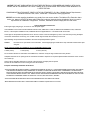
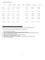
IMPORTANT
FOR FUTURE REFERENCE
Please complete this information
and retain this manual for the life
of the equipment.
MODEL #———————————————————
SERIAL #———————————————————
DATE PURCHASED——————————————
For Warranty Service and/or Parts this
information is required.
PRODUCT MANUAL
Safety Instructions
Installation Instructions
Operation Instructions
Maintenance Instructions
Replacement Parts List
Warranty/Service Information
Gas Char-broilers
and
Charrock Gas Broilers
Models GCB-18H, GCB-24H, GCB-36H, GCB-48H
And
Models GCRB-18H, GCRB-24H, GCRB-29H, GCRB-48H
FOR YOUR SAFETY
Do not store or use gasoline or other flammable vapors or
liquids in the vicinity of this or any other appliance.
!
WARNING
Improper installation, adjustment, alteration, service or maintenance can
cause property damage, injury or death. Read the installation, operating
and maintenance instructions thoroughly before installing or servicing this equipment.
APW/WYOTT Foodservice Equipment Co.
P.O. Box 1829
Cheyenne, WY 82003
(307) 634-5801
FAX(307) 637-8071
1
! CAUTION
These models are designed, built and sold for commercial use. If these models are positioned so the general public can use
the equipment, make sure that all cautions, warnings and operating instructions are clearly posted near each unit so that
anyone using the equipment will use it correctly and not injure themselves or harm the equipment.
! WARNING
Improper installation, operation, service or maintenance can cause property damage, injury or death. Read
these instructions thoroughly before installing, operating, maintaining or servicing this equipment.
Install per the spacing requirements listed in the installation section of this manual. We strongly recommend
having a competent professional install this equipment. Such a person should be familiar with local gas
regulations. A gas company representative should approve the completed installation.
!
WARNING
FOR YOUR SAFETY DO NOT STORE OR USE GASOLINE OR OTHER FLAMMABLE LIQUIDS AND
VAPORS IN THE VICINITY OF THIS OR ANY OTHER APPLIANCE. KEEP THE AREA FREE AND
CLEAR OF COMBUSTIBLES. (SEE ANZI Z83.14B, 1991)
Instructions to be followed if any one smells gas should be posted in a prominent place. These may be
obtained from the gas supplier.
GAS PRESSURE
The appliance and its individual shutoff valve must be disconnected from the gas supply piping system
during any pressure testing of that
system at test pressures in excess of 1/2 psi (3.45 kPa)
The appliance must be isolated from the gas supply piping system by closing its individual manual shutoff valve during any pressure testing of the gas supply piping system at test pressures equal to or less
than 1/2 psi (3.45 kPa)
Maintenance and repair should be handled by a factory authorized agent. Before doing any maintenance or repair, contact APW/Wyott.
Congratulations on your purchase of APW/Wyott commercial cooking or refrigeration equipment. APW/Wyott takes pride in
the design and quality of our products. When used as intended and with proper care and maintenance, you will experience
years of reliable operation from this equipment. To assure best results, it is important that you read and follow the instructions in this manual carefully.
TABLE OF CONTENTS:
Safety Precautions ........................................... 4
Specifications ................................................... 5
Installation ....................................................... 5
European Installation ....................................... 5
Lighting Instructions ......................................... 6
Operating Instructions ...................................... 8
Cleaning / Maintenance.................................... 9
Service / Repair ............................................. 10
Conversion ..................................................... 10
Parts Diagram ................................................ 11
Parts List ................................................... 12-15
Warranty ........................................................ 16
LOCATION OF DATA PLATE
The data plate is located on the back side of the front panel.
2
IMMEDIATELY INSPECT FOR SHIPPING DAMAGE
All containers should be examined for damage before and during unloading. The freight carrier has assumed responsibility for its safe transit and delivery. If equipment is received damaged, either apparent or concealed, a claim must be
made with the delivering carrier.
A) Apparent damage or loss must be noted on the freight bill at the time of delivery. It must then be signed by the carrier representative (Driver). If this is not done, the carrier may refuse the claim. The carrier can supply the necessary
forms.
B) Concealed damage or loss if not apparent until after equipment is uncrated, a request for inspection must be made
to the carrier within 15 days. The carrier should arrange an inspection. Be certain to hold all contents and packaging
material.
Installation and start-up should be performed by a qualified installer who thoroughly read, understands and follows
these instruction.
If you have questions concerning the installation, operation, maintenance or service of this product, write Technical
Service Department APW/Wyott Foodservice Equipment Company, P.O. Box 1829, Cheyenne, WY 82003.
SAFETY PRECAUTIONS
Before installing and operating this equipment be sure everyone involved in its operation are fully trained and are
aware of all precautions. Accidents and problems can result by a failure to follow fundamental rules and precautions.
SAFETY PRECAUTIONS
Before installing and operating this equipment be sure everyone involved in its operation are fully trained and are
aware of all precautions. Accidents and problems can result by a failure to follow fundamental rules and precautions.
! DANGER
This symbol warns of imminent hazard which will result in serious injury or death.
! CAUTION
This symbol refers to a potential hazard or unsafe practice which may result in minor or moderate injury or product or
property damage.
NOTICE
This symbol refers to information that needs special attention or must be fully understood even though not
dangerous.
NOTICE
This product is intended for commercial use only. Not for household use.
! CAUTION
The models are designed, built and sold for commercial use. If these models are positioned so the general public can
use the equipment, make sure that all cautions, warnings and operating instructions are clearly posted near each unit
so that anyone using the equipment will use it correctly and not injure themselves of harm the equipment.
! WARNING
SHOCK HAZARD
Do not open any panels that require the use of tools.
! WARNING
Improper installation, service, or maintenance can cause property damage, injury or death.
3
NOTICE THE UNIT, WHEN INSTALLED, MUST BE ELECTRICALLY GROUNDED AND COMPLY WITH LOCAL
CODES, OR IN THE ABSENCE OF LOCAL CODES, WITH THE NATIONAL ELECTRICAL CODE ANSI/NFPA 70LATEST EDITION.
CANADIAN INSTALLATION MUST COMPLY WITH CSA-STANDARD C.22.2 No. 0 M1982 General Requirements Canadian Electrical Code, Part II, 109-M1981 - Commercial Cooking Appliances.
NOTICE Local codes regarding installation vary greatly from one area to another. The National Fire Protection Association, Inc. states in its NFPA 96 latest edition that local codes are "authority having jurisdiction" when it comes to
requirements for installation of equipment. Therefore, installations should comply with all Local codes.
General Installation Instructions:
Ensure gas supply and gas type, as shown on unit nameplate agree.
Unit installation must conform with the National Fuel Gas Code, ANSI Z223.1-1996, the National Gas Installation Code, CAN/CGAB149.1, or the Propane Installation Code, CAN/CGA-B149.2 as applicable and in accordance with local codes.
Screw legs into the permanently fastened nuts on the four corners of the unit and tighten by hand. Level the unit by turning the adjustment screw at the bottom of each leg. Do not slide unit with legs mounted, lift if necessary to move unit.
Pipe threading compound must be resistant to the action of liquefied petroleum gases.
Caution:
DO NOT use an open flame to check for leaks. Check all gas piping for leaks with a soap and water solution before operating unit.
These units are suitable for installation on non-combustible surfaces only.
Noncombustible clearances:
0” sides (0 mm)
0” rear (0 mm)
4” floor (102 mm)
Do not obstruct the flow of combustion and ventilation air, under the unit by the legs or behind the unit by the flue.
Adequate clearance for air openings into the combustion chamber is required. Do not place objects between the bottom of the unit and
the counter top.
There must be adequate clearance for removal of the front panel. All major parts except the
burners are removable thru the front if the gas line is disconnected.
European Community Installation Instructions:
“THIS APPLIANCE MUST BE FITTED BY A COMPETENT PERSON. IN THE U.K., CORGI REGISTERED INSTALLERS (INCLUDING
THE REGIONS OF BRITISH GAS) UNDERTAKE TO WORK TO SAFE AND SATISFACTORY STANDARDS. THIS APPLIANCE
MUST BE INSTALLED IN ACCORDANCE WITH THE GAS SAFETY (INSTALLATION AND USE) REGULATIONS AND THE RELEVANT BUILDING REGULATIONS / I.E.E. REGULATIONS. DETAILED RECOMMENDATIONS ARE CONTAINED IN THE FOLLOWING BRITISH STANDARD CODES OF PRACTICE - BS 6172, BS 5440 PART 2, BS 6891”
“THIS APPLIANCE MUST BE INSTALLED IN ACCORDANCE WITH THE RULES IN FORCE”
“MUST BE INSTALLED IN A WELL VENTILATED AREA. Ventilation requirements ie. B.S. 5440.”
4
Specifications And Dimensions:
Model
Width
in. (mm)
Depth
in. (mm)
Height
in. (mm)
No. of
Burners
BTU/kW Per Burner
Natural gas
Total
BTU / kW Hour
W.C.
in. (‘mbar’)
GCB-18H
18 (457)
25 (635)
15.5 (394)
1
60,000/17.5
60,000/17.5
6/10(15/25)
GCB-24H
24 (610)
25 (635)
15.5 (394)
2
40,000/11.7
80,000/23.5
6/10(15/25)
GCB-36H
36 (914)
25 (635)
15.5 (394)
2
60,000/17.5
120,000/35
6/10(15/25)
GCB-48H
48 (1220)
25 (635)
15.5 (394)
4
40,000/11.7
160,000/46.8
6/10(15/25)
GCRB-18H
18 (457)
25 (635)
15.5 (394)
1
60,000/17.5
60,000/17.5
6/10(15/25)
GCRB-24H
24 (610)
25 (635)
15.5 (394)
2
40,000/11.7
80,000/23.5
6/10(15/25)
GCRB-36H
36 (914)
25 (635)
15.5 (394)
2
60,000/17.5
120,000/35
6/10(15/25)
GCRB-48H
48 (1220)
25 (635)
15.5 (394)
4
40,000/11.7
160,000/46.8
6/10(15/25)
CONVERSION (Not Available in the European Community
Instructions are for conversion from Natural Gas to Propane (L.P.) on all models GCRB and GCB.
The conversion should b done before connecting the unit to the gas supply.
1.
2.
3.
4.
5.
6.
7.
8.
Remove the knobs and front panel.
Remove the supply tubes that go between the valves and the orifice fittings.
Remove the orifice fittings from the firebox. Change the orifices to the size recommended for propane (L.P.).
Replace the orifice fittings into the firebox.
Replace the supply tubes between the valves and the orifice fittings.
Replace the front panel, grease drawer and knobs.
Reverse plug in pressure regulator. The marking on the plug facing out should match gas supply.
Continue with the installation.
5
Lighting Instructions:
GCB and GCRB Broilers are furnished with either a pilot safety valve or a standing pilot
(not available in the European Community). Please follow the instructions for your unit.
Pilot Safety Valve Lighting Instructions:
Lighting instructions are inside the front panel. To open front panel:
•
Remove thumb screws from front panel, lift the front panel off of the unit.
If the pilot goes out, an automatic shutoff valve turns off the gas supply to the burners. To relight the pilot, follow this
procedure:
•
Turn the control valve to "OFF". Wait a sufficient length of time to allow gas, which may have accumulated in the burner
compartment, to escape (at least five minutes).
•
Turn on the main shutoff valve.
•
Depress and hold in the red button "A" on the automatic shutoff valve while lighting the pilot burner.
•
When gas at pilot has been burning for about 45 seconds, release the red button. If pilot does not remain lit, repeat the
operation, allowing more time before releasing red reset button.
•
To adjust the pilot flame, Rotate the knob clockwise to reduce the gas flow, and counterclockwise to increase the gas
flow; to provide a properly sized pilot flame (approximately 1/ 2" to 3/4" long). (12 to 19 mm)
•
All units are equipped with fixed orifices for use with natural gas, and no adjustment is necessary.
•
Units for operation on natural or propane gas, are also equipped with a factory preset pressure regulator with an outlet
pressure of 6.0" W.C. (15 ‘mbar’) for natural gas supply, and 10" W.C. (25 ‘mbar’) for propane gas supply, and should
not require further adjustment.
Standing Pilot Lighting Instructions: ( Not Available in the European Community )
The pilot lights on the broilers have been set at the factory. A screwdriver maybe required for the first lighting to adjust the
flame for your elevation.
1 Turn off the manual shut off valve and wait 5 minutes to clear the gas.
2 Turn all knobs to the “OFF” position.
3 Remove the grease drawer and front panel for easy access.
4 Turn the manual shut off valve on.
5 Hold an ignition source (match) at the pilot tube. When the flame is established, remove the ignition source.
NOTE: Standing pilot lighter arms must be lit in two (2) locations. At the end of the tube and in the bend.
6 Turn the burner knobs to “HI”. If the burner does not ignite, promptly open the pilot valve more. If the pilot flame appears
larger than necessary, turn it down and reset burner ignition. The pilot flame should be as small as possible but large
enough to guarantee reliable ignition of the burners when the knobs are turned to “HI”.
7 Replace the front panel and grease drawer.
RELIGHTING PILOT
If the pilot light should go out for any reason:
• Promptly shut off all gas at the manual shut off valve.
• Turn off all knobs and pilot valves; wait 5 minutes to clear gas.
• Relight following steps 3 through 8 under Standing Pilot Lighting Instructions.
6
Lighting main burner:
Since the burner is lit from constantly burning pilot, turn knobs to “HI” to put the unit in operation; then adjust to any
desired position between “LO” and “HI”.
•
•
•
•
•
•
To light burner, turn knob to "max." then back off to the desired flame level. The range of adjustment is virtually infinite
between high and off.
When the broiler is first heated, it will smoke until oil used in manufacturing, preservation and dust from storage and shipping are burned off. An hour at "max." on all burners is usually sufficient.
Turn knobs off and let cool
For first cooking, set the grates at maximum tilt position and preheat before broiling. You will have to experiment with
knob settings and grate position for each particular meat item.
Keep the grease/water pan with sufficient water to cover the entire bottom.
Clean regularly. Grates may be removed for washing in the sink. Brush out carbonized particles. Thoroughly wash the
grease/water pan.
CAUTION
Never attempt to move a grill section while cooking. An unexpected flare could cause severe injury. Turn off the unit, let it
cool and use potholders and/or gloves to reposition or remove. The space between the legs at the bottom admits combustion air. DO NOT BLOCK THIS SPACE.
Main burner air supply:
For efficient burner operation, a proper balance of gas volume and primary air supply must be maintained which will result in
complete combustion. Insufficient air supply results in a yellow streaming flame. Primary air supply is controlled by an air
shutter on the front of the burner.
Loosen the screws on the front of the burner, and adjust the air shutter to just eliminate the yellow tips of the burner flame.
Lock the air shutter in place by tightening the screws.
European Community:
If adjustment becomes necessary in the field, it should be done by a factory authorized and trained technician who
should seal the screw after the adjustment to safeguard against un-authorized tampering by the end user.
All burners are lit from constantly burning pilots. Turning the thermostat to the desired temperature is all that is required to
put the unit in service.
Do not permit fans to blow directly at the unit. Wherever possible, avoid open windows next to the units’ sides or back.
Avoid wall type fans which create air cross-currents within a room
It is also necessary that sufficient air should be allowed to enter the room to compensate for
the amount of air removed
by any ventilating system. Otherwise, a subnormal atmospheric pressure will occur, affecting operation and causing undesirable working conditions.
A properly designed and installed hood will act as the heart of the ventilating system for the
room or area in which the unit is installed, and will leave the unit independent of changing draft conditions.
All valves and thermostats must be checked and lubricated periodically. Consult the authorized service representative in
your area.
6
Operating Instructions:
Operation: Turn the burners on about 15-20 minutes before cooking for preheating. Set the knobs to the desired flame
height or temperature. Each valve will control the gas flow to the burner to bring that area of the unit up to the set temperature. If different temperature settings are to be used, adjoining areas should be set at progressively higher temperatures using the lowest temperatures on the outside burners. A uniform and systematic approach to the loading of the unit will produce the most consistent product results.
RADIANTS
Place the radiants in their position as shown in Sketch 1. Make sure that the radiants are setting properly on the front and
rear supports (between the positioning tabs). Radiants should be centered over straight section of the burners.
COOKING GRATES
Place the top cooking grates with the grid bars sloping toward the front as shown in Sketch 2.
Note: When cooking grates are placed sloping toward the front, the grooves on top will guide the excess fat drippings into
the grease trough.
7
Cleaning / Maintenance:
Initial Cleaning:
Prior to operating your new broiler, thoroughly wash the exterior with a mild detergent or soap solution. do not use abrasive cleaners, since this might damage the cabinet finish. If the stainless steel surfaces become discolored, scrub by
rubbing only in the direction of the finished grain.
When the broiler is first heated, it will smoke until oil used in manufacturing, preservation and dust from storage and
shipping are burned off. An hour at "max." on all burners is usually sufficient.
Cleaning:
DAILY
Remove the grease pan, empty and wash it.
Grate "burn off". The grease buildup on the grates should be cleaned daily (more often as needed).
a.
b.
c.
d.
e.
f.
g.
h.
Caution, When handling grates or radiants, always use insulated gloves to prevent burns.
Warning, Do not cover the top of the grid grates during a burn off operation. Restricting the airflow by covering the grid
grates may cause them to warp.
Place grates on broiler, with grid bars horizontal, facing down.
Turn control knobs to "HI" for approximately 45 minutes.
Turn off the broiler and allow it to cool for 20 Minutes.
Clean top and bottom surfaces of grate with a wire brush to remove animal fats and carbonized grease.
Clean channels on grates with a scraper.
Remove grates from broiler. Clean top surface of radiants with the wire brush. They may be cleaned in place.
WEEKLY
Thoroughly clean the exposed surfaces of broiler, sides, front and top grease trough, with a damp cloth, then polish with a
soft, dry cloth. A detergent may be used for cleaning. To remove discoloration, use a non-abrasive cleaner.
After performing daily cleaning procedures, proceed with the following:
a.
Remove the radiants. Clean reflecting drip shield of any dust or debris with a brush.
Note:
b.
c.
Top grid grates and radiants are heavy. They may break if dropped or bumped.
Burner air shutter openings must be kept clean.
Burner ports must be kept clean. To clean burners, boil them in a strong solution of lye water for fifteen to twenty minutes. Then, either brush with a wire brush or clean gas ports with a sharp-pointed metal instrument to insure open
ports.
Extended Shutdown:
Turn the manual shutoff valve to “OFF”; (field installed valve not supplied by the manufacturer), turn all control knobs to
the “OFF” position and shut off the pilot flame by turning the adjustment on the pilot valve.
8
Service / Repair:
NOTE; THIS APPLIANCE MUST ONLY BE SERVICED BY AN AUTHORIZED
AGENT.
NOTE: Parts protected by the manufacturer or his agent are not to be adjusted by the
installer, unless the installer is an authorized service agent.
Conversion: (Not Available In The European Community)
These units are not field convertible. Any conversion to these units must be done by an authorized service agent.
If you have any questions or problems contact your nearest
APW/Wyott
Service Representative.
PLACE LAVA ROCKS WITH AIR SPACES
BETWEEN THE ROCKS,
DONOT OVER LOAD ROCK GRATES.
9
K
L
M
N
G
H
I
J
C
D
E
F
A
B
GCRB-18H VIEWABLE PILOT
GCRB-18H PILOT SAFETY
VALVE
GCB-18H PILOT SAFETY VALVE
GCB-18H VIEWABLE PILOT
GCRB-24H VIEWABLE PILOT
GCRB-24H PILOT SAFETY
VALVE
GCB-24H PILOT SAFETY VALVE
GCB-24H VIEWABLE PILOT
GCRB-36H VIEWABLE PILOT
GCRB-36H PILOT SAFETY
VALVE
GCB-36H PILOT SAFETY VALVE
GCB-36H VIEWABLE PILOT
GCRB-48H VIEWABLE PILOT
GCRB-48H PILOT SAFETY
UNIT DESCRIPTIONS
10
11
218132-29
218133-29
218130-67
218131-67
218132-67
218133-67
11
11
12
12
12
12
218132-24
6
218131-29
218131-75
5
11
218130-75
4
218130-29
83530-00
3
11
218133-28
2
218131-65
218132-28
2
10
218131-28
2
31022-05
218130-28
2
9
218133-33
1
31022-00
218132-33
1
8
218131-33
1
218133-24
218130-33
1
7
PART NUMBER
ITEM
1
1
1
1
1
1
1
1
V.
V.
V.
V.
V.
V.
V.
4
2
2
2
2
1
1
1
1
REQD.
HEAT BAFFLE REAR -48
HEAT BAFFLE REAR -36
HEAT BAFFLE REAR -24
HEAT BAFFLE REAR -18
GRATE SUPPORT -48
GRATE SUPPORT -36
GRATE SUPPORT -24
GRATE SUPPORT -18
RADIANT
GRATE ROCK HOLDER
GRATE COOKING
SHIELD, BURNER
SHIELD, BURNER
U BURNER WELD ASSY.
S BURNER WELD ASSY.
POP RIVET, 1/8" S/S
BURNER SUPPORT -48
BURNER SUPPORT -36
BURNER SUPPORT -24
BURNER SUPPORT -18
BODY WELDMENT -48
BODY WELDMENT -36
BODY WELDMENT -24
BODY WELDMENT -18
DESCRIPTION
A
A
A
A
A
A
A
A
A
B
B
B
B
B
B
B
B
B
UNITS
C
C
C
C
C
C
C
C
D
D
D
D
D
D
D
D
E
E
E
E
E
E
E
E
E
F
F
F
F
F
F
F
F
F
G
G
G
G
G
G
G
G
H
H
H
H
H
H
H
H
I
I
I
I
I
I
I
I
I
I
J
J
J
J
J
J
J
J
J
J
K
K
K
K
K
K
K
K
L
L
L
L
L
L
L
L
M
M
M
M
M
M
M
M
M
N
N
N
N
N
N
N
N
N
O
O
O
O
O
O
O
O
P
P
P
P
P
P
P
P
12
87056-00
87055-15
218130-70
218131-70
218132-70
218133-70
23
24
25
25
25
25
81966-02
19
218133-16
218131-91
18
22
218132-38
18
218132-16
218131-91
18
22
218130-38
18
218131-16
218133-15
17
22
218132-15
17
218130-16
218131-15
17
22
218130-15
17
31007-24
20926-10
16
21
20925-17
15
86320-00
20926-11
14
20
20926-13
13
1
1
1
1
V.
V.
1
1
1
1
4
4
4
2
1
1
1
1
1
1
1
1
1
1
1
GRAPHICS FRONT -48
GRAPHICS FRONT -36
GRAPHICS FRONT -24
GRAPHICS FRONT -18
PLATE DIAL
KNOB CONTROL
PANEL FRONT -48
PANEL FRONT -36
PANEL FRONT -24
PANEL FRONT -18
SCREW CAPTIVE
LEG 4”
RETAINER
PAN WATER -24
PAN WATER -36
PAN WATER -24
PAN WATER -18
BACK PANEL -48
BACK PANEL -36
BACK PANEL -24
BACK PANEL -18
COUPLING 3/4”
NIPPLE 3”
ELBOW 3/4”
PIPE INLET
A
A
A
A
A
A
A
A
A
A
A
A
A
B
B
B
B
B
B
B
B
B
B
B
B
B
C
C
C
C
C
C
C
C
C
C
C
C
C
D
D
D
D
D
D
D
D
D
D
D
D
D
E
E
E
E
E
E
E
E
E
E
E
E
E
F
F
F
F
F
F
F
F
F
F
F
F
F
G
G
G
G
G
G
G
G
G
G
G
G
G
H
H
H
H
H
H
H
H
H
H
H
H
H
I
I
I
I
I
I
I
I
I
I
I
I
I
J
J
J
J
J
J
J
J
J
J
J
J
J
K
K
K
K
K
K
K
K
K
K
K
K
K
L
L
L
L
L
L
L
L
L
L
L
L
L
M
M
M
M
M
M
M
M
M
M
M
M
M
N
N
N
N
N
N
N
N
N
N
N
N
N
O
O
O
O
O
O
O
O
O
O
O
O
O
P
P
P
P
P
P
P
P
P
P
P
P
P
13
20925-17
20668-29
20668-35
20668-29
20668-35
218105-70
20928-00
38
38
38
38
39
40
20680-00
33
37
218133-14
32
218133-35
218131-35
218132-14
32
36
218131-14
32
218132-35
218130-14
32
36
300475-07
31
218131-35
218133-13
30
36
81966-01
29
218130-35
81531-00
28
36
300475-08
27
218105-75
218133-38
26
35
218132-39
26
20680-01
218131-38
26
34
218130-39
26
V.
V.
4
2
2
1
V.
1
1
1
1
1
V.
V.
V.
2
2
2
2
1
2
4
4
1
1
1
1
1
PILOT
PILOT SUPPORT BRKT
ORIFICE HOOD#35
ORIFICE HOOD#29
ORIFICE HOOD#35
ORIFICE HOOD#29
PLUG 1/8 NPT
MANIFOLD -48
MANIFOLD -36
MANIFOLD -24
MANIFOLD -18
TUBE PILOT
VALVE PILOT
VALVE GAS
LEG SUPPORT -48
LEG SUPPORT -36
LEG SUPPORT -24
LEG SUPPORT -18
GUIDE LEFT SIDE
PANEL SIDE
RECEPTACLE CLIP-ON
#8-32 MACHINE SCREW
GUIDE RIGHT HAND
BAFFLE FRONT PANEL -48
BAFFLE FRONT PANEL -36
BAFFLE FRONT PANEL -24
BAFFLE FRONT PANEL -18
A
A
A
A
A
A
A
A
A
A
A
A
A
A
B
B
B
B
B
B
B
B
B
B
B
B
C
C
C
C
C
C
C
C
C
C
C
C
D
D
D
D
D
D
D
D
D
D
D
D
D
D
E
E
E
E
E
E
E
E
E
E
E
E
E
E
F
F
F
F
F
F
F
F
F
F
F
F
G
G
G
G
G
G
G
G
G
G
G
G
H
H
H
H
H
H
H
H
H
H
H
H
H
H
I
I
I
I
I
I
I
I
I
I
I
I
I
I
J
J
J
J
J
J
J
J
J
J
J
J
K
K
K
K
K
K
K
K
K
K
K
K
L
L
L
L
L
L
L
L
L
L
L
L
L
L
M
M
M
M
M
M
M
M
M
M
M
M
M
M
N
N
N
N
N
N
N
N
N
N
N
N
O
O
O
O
O
O
O
O
O
O
O
O
P
P
P
P
P
P
P
P
P
P
P
P
P
P
14
218133-34
218133-39
20932-00
20927-02
218131-79
41
42
43
44
45
V.
V.
V.
V.
V.
PILOT SUPPLY TUBE
PILOT SAFETY VALVE
THERMO-COUPLE
PILOT SHIELD
PILOT BRACKET
B
B
B
B
B
C
C
C
C
C
F
F
F
F
F
G
G
G
G
G
J
J
J
J
J
K
K
K
K
K
N
N
N
N
N
O
O
O
O
O
APW/WYOTT EQUIPMENT LIMITED WARRANTY
APW/WYOTT Foodservice Equipment Company warrants its equipment against defects in materials and workmanship, subject to the following conditions:
This warranty applies to the original owner only and is not assignable.
Should any product fail to function in its intended manner under normal use within the limits defined in this warranty, at the option of APW/WYOTT
such product will be repaired or replaced by APW/WYOTT or its Authorized Service Agency. APW/WYOTT will only be responsible for charges
incurred or service performed by its Authorized Agencies. The use of other than APW/WYOTT Authorized Service Agencies will void this warranty
and APW/WYOTT will not be responsible for such work or any charges associated with same. The closest APW/WYOTT Authorized Service
Agency must be used.
This warranty covers products shipped into the 48 contiguous United States, Hawaii, metropolitan areas of Alaska and Canada. There will be no labor
coverage for equipment located on any island not connected by roadway to the mainland.
TIME PERIOD:
One-year parts, one-year labor, effective from the date of purchase by the original owner. The Authorized Service Agency may, at their option, require
proof of purchase. Parts replaced under this warranty are warranted for the unexpired portion of the original product warranty only.
EXCEPTIONS:
*Gas/Electric Cookline - Models GCB, GCRB, GF, GGM, GGT, GHP-H, GWW, EBC, EF, EG, EHP, EWW Three (3) Year Warranty on all
component part, except switches and thermostats. (2 additional years on parts only - No labor on second or third year.)
*Heat Strips - Models FD - Two (2) Year Warranty on element only - No labor second year.
*Glass Windows, Door Seals, Rubber Seals, Light Bulbs, Broiler Briquettes 90 Day Material Only - No labor.
In all cases parts covered by extended warranty will be shipped FOB the factory after the first year.
PORTABLE CARRY-IN PRODUCTS
Equipment weighing over 70 pounds or permanently installed will be serviced on-site as per the terms of this warranty. Equipment weighing 70
pounds or under, and which is not permanently installed i.e., with cord and plug, is considered portable and is subject to the following warranty handling limitations.
If portable equipment fails to operate in its intended manner on the first day of connection, or use, at APW/WYOTT's option or its Authorized Service
Agency, it will be serviced on-site or replaced.
From day two through the conclusion of this warranty, portable units must be taken or sent prepaid to the APW/WYOTT Authorized Service Agency
for in-warranty repairs. No mileage or travel charges are allowed on portable units after the first day of use. If the customer wants on-site service they
may receive same by paying the travel and mileage charges.
EXCLUSIONS:
The following conditions are not covered by warranty.
*Equipment failure relating to improper installation, improper utility connection or supply and problems due to ventilation.
*Equipment that has not been properly maintained, calibration of controls, adjustments, damage from improper cleaning and water damaged controls.
*Equipment that has not been used in an appropriate manner, or has been subject to misuse or misapplication, neglect, abuse, accident, alteration, negligence, damage during transit, delivery or installation, fire, flood, not or act of God.
*Equipment that has had the model number or serial number removed or altered.
If the equipment has been changed, altered, modified or repaired by other than a qualified service technician during or after the warranty period then
the manufacturer shall not be liable for any damages to any person or property which may result from the use of the equipment thereafter.
This warranty does not cover services performed at overtime or premium labor rates. Should service be required at times which normally involve
overtime or premium labor rates, the owner shall be charged for the difference between normal service rates and such premium rates APW/WYOTT
does not assume any liability for extended delays in replacing or repairing any items beyond its control.
In all cases the use of other than APW/WYOTT authorized OEM replacement parts will void this warranty.
This equipment is intended for commercial use only. Warranty is void if equipment is installed in other than commercial application.
THE FOREGOING WARRANTY IS IN LIEU OF ANY AND ALL OTHER WARRANTIES EXPRESSED OR IMPLIED INCLUDING ANY IMPLIED WARRANTY OF MERCHANTABILITY OR FITNESS AND CONSTITUTES THE ENTIRE LIABILITY OF APW/WYOTT IN NO
EVENT DOES THE LIMITED WARRANTY EXTEND BEYOND THE TERMS STATED HEREIN.
P/N 88357-24 04 /99 REV A
15
17
16