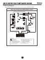
1
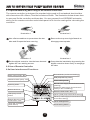
AIR TO WATER
HEAT PUMP WATER HEATER
Owner s Manual
BOLT-ON split system models:
MAHRW010ZB/P
MAHRW010ZB-250SS
MAHRW010ZB-315SS
MAHRW010ZB-250VEO
MAHRW010ZB-315VEO
without tank
stainless steel tank
stainless steel tank
vitreous enamel tank
vitreous enamel tank
http://www.siddonssolarstream.com
CODE:MK4068-02
SIDDONS SOLARSTREAM Pty Ltd
AIR TO WATER HEAT PUMP WATER HEATER
Contents
1. One of the World's Most Efficient Ways to Heat Water....................................... 4
1.1 Introduction................................................................................................ 4
1.2 Dynamic Cycle Flow Heating System.............................................................4
1.3 Reduce Greenhouse Emissions................................................................... 4
1.4 Specifications.............................................................................................. 5
1.5 Schematic................................................................................................... 6
2. Installation Details........................................................................................... 6
2.1 General Installation Requirements............................................................. 6
2.2 Not suitable for Pools and Spas................................................................... 6
2.3 Heat Pump Positioning................................................................................ 6
2.4 Evaporator Drain......................................................................................... 7
2.5 Water Pipe Connections .............................................................................. 7
2.6 Electrical Connection ................................................................................. 8
2.7 Storage Tank Positioning............................................................................ 9
2.8 Outdoor Installations.................................................................................. 9
2.9 Indoor Installations..................................................................................... 9
2.10 Siesmic Restraint...................................................................................... 9
2.11 Filling the Storage Tank............................................................................. 9
2.12 Legionella.................................................................................................10
2.13 Scalding................................................................................................... 10
2.14 Pressure Limiting Valve............................................................................ 10
2.15 Cold Water Expansion Control Valve.........................................................10
2.16 Stop / Isolating Valve................................................................................ 10
2.17 Pressure and Temperature Relief Valve .................................................... 10
2.18 Hot Water Connection.............................................................................. 11
2.19 Tempering Valves.................................................................................... 11
2.20 Plumbing Components QIK Kit................................................................. 11
2.21 Corrosion Protection .............................................................................. 12
3. Operating Instructions................................................................................... 12
3.1 Powering Up............................................................................................... 12
3.2 Pressure and Temperature Relief Valve Maintenance.................................. 12
3.3 Water Quality.............................................................................................. 13
3.4 Anode.........................................................................................................13
3.5 Draining the tank........................................................................................ 13
1
AIR TO WATER HEAT PUMP WATER HEATER
Contents
4. Storage Tank Specifications........................................................................... 14
4.1 Stainless Steel Storage Tank Models.......................................................... 14
4.2 Glass Lined / Vitreous Enamel Storage Tank Models................................... 14
5. Safety Information...........................................................................................14
5.1 Safety Devices........................................................................................... 14
5.2 Water Heater Unused for Long Periods ....................................................... 15
6. Maintainance & Service Information................................................................ 15
6.1 No Puncturing the Water Tank ................................................................... 15
6.2 Cleaning the Evaporator Coils................................................................... 15
6.3 Sacrificial Anode....................................................................................... 15
6.4 Capacitors................................................................................................. 15
7. Routine Service.............................................................................................. 16
7.1 Access and removal of Sacrifical Anode.................................................... 16
7.2 Flushing of Water Tank.............................................................................. 16
7.3 Thermal Overload (Incorporated in Digital Controller) .............................. 16
8. Operation & Adjustment of the Digital Controller............................................. 16
8.1 Optional Mounting and Fixing of the Remote Controller........... ............... 17
8.2 Use of remote controller ........................................................................... 17
8.2a The user interface and function shows as below.................................... 17
8.2b Initial Power On and Standby Status..................................................... 18
8.2c ON/OFF Control.................................................................................... 18
8.2d
Electric Heater Control......................................................................... 18
.
8.2 e Turning On/Off the Ring Main Water Circulating Pump Manually.... ................ 19
8.2f Clock Setting......................................................................................... 19
8.2g Timer 1 ON/OFF Setting..........................................................................19
8.2h Setting of Timer 2, Ring Main Water Supply Flow and Return Line ................... 19
8.2i Cancellation of Timing Setting Operation ............................................... 20
8.2j Parameter Setting .................................................................................. 20
8.3 Operation Data Setting............................................................................................ 21
9. Recognition of Abnormal Operation............................................................... 22
9.1 Pressure & Temperature Relief Valve Running........................................... 22
9.1a Continuous Trickle................................................................................ 22
9.1b Steady Flow........................................................................................... 22
9.2 No Hot Water............................................................................................ 22
2
AIR TO WATER HEAT PUMP WATER HEATER
Contents
10. System Malfunction Schedule............................................................................ 23
11. Judgement and Solution of Malfunctions........................................................24
12. Wiring Diagram.............................................................................................. 25
13. Warranty Policy (Australia Only).................................................................... 26
13.1 Warranty Terms......................................................................................... 26
13.2 Warranty Conditions................................................................................. 26
13.3 Exclusions................................................................................................ 27
13.4 Water Quality Limits - Warranty Exclusion................................................. 27
13.5 How to make a Warranty Claim................................................................... 28
13.6 Tanamet Crystal Water Filters................................................................... 28
13.7 Australian Consumer Law......................................................................... 28
3
AIR TO WATER HEAT PUMP WATER HEATER
1. One of the World's Most Efficient Ways to Heat Water
1.1 Introduction
Congratulations on purchasing a SIDDONS Solarstream energy efficient Heat Pump Water
Heater, designed for Australian conditions to produce many years of low energy hot water.
This water heater typically uses up to 75% less energy than a conventional electric element
water heater by absorbing heat from the surrounding air of between -5 and 45 degrees C,
night and day. It works in hail, rain and shine and becomes more efficient as the air
temperature and humidity rise. You can expect around 20% greater efficiency per 10 degree
rise in the ambient air temperature.
SIDDONS, with its partners, designs and manufactures energy efficient Heat Pump Water
Heaters for global markets using the best quality components sourced from Australia,
Germany, Japan and China.
Heat Pump Water Heaters can be used for factories, schools, hotels, motels, restaurants,
hospitals, beauty salons, spas, laundries, etc.
1.2 Dynamic Cycle Flow Heating System
The Dynamic Cycle flow heating system is used to convert an average of 1 kW/h of input
electrical energy into 3.5 kW/h of heat energy, more or less, depending on ambient air
temperature and humidity. Cold water from the bottom of the storage tank is cycled through
the heat exchanger in the Heat Pump outdoor unit then back to the storage tank until all the
water is completely heated.
As the name implies, an air to water Heat Pump Water Heater is a machine that pumps or
transfers heat absorbed from the ambient air into the water. Even at - 5 deg C, there is
enough heat in the air to boil the liquid refrigerant into a gas. Once in the form of a gas, it
can be compressed to superheat up to 95 deg C; this heat is then pumped into the water
through a double layered, tube inside tube heat exchanger. One tube takes the hot
compressed gas whilst the other takes the cold water from the tank. The advantages of
this method are:
· Excellent heating efficiency
· Stable hot water without over heating at the top or under heating at the bottom
· All of the tank water is heated
1.3 Reduce Greenhouse Emissions
With a SIDDONS Solarstream, you are greatly assisting the reduction of global greenhouse
gas emissions if you can replace bottled gas, wood fired or a conventional electric element
water heater, the latter typically consumes 1/4 to 1/3 of a household's power usage. If you want
your water heater to be completely carbon neutral, then also install a small electricity
generating system such as a Photo Voltaic solar panel or wind power.
4
AIR TO WATER HEAT PUMP WATER HEATER
1.4 Specifications
Model Nomenclature
MA HR W S - * ** - W A B / P S (B D)
Source medium
MA: Air source
MW: Ground source
D: With electrical heating
(Without electrical heating omitted)
B: Inverter
E: EVI
Function of the unit
HR: Heating
(Without inverter or EVI omitted)
Energy exchange medium
A: Refrigerant
W: Water
S: 3phase (single phase omitted)
P: With built in pump
(without built in pump omitted)
S: With solar
(Without solar omitted)
A: Coil heating
B: Circulating heating
The figure represents the horse power of unit
eg: 010 means 1 horse power
A: Horizontal fan direction
B: Upward fan direction
C: Double air duct type
Z: Integrated type
W: Split type(indoor unit )
Model Number
Rated Heating Capacity (1)
Rated Input Power (1)
Rated Input Current (1)
Rated COP (1)
Rated Heating Capacity (2)
Rated Input Power (2)
Rated Input Current (2)
Rated COP (2)
Hot Water Recovery Rate (average)
Maximum input current
Power Supply
Maximum water inlet temperature
Maximum water outlet temperature
Noise
Compressor type
Water Outlet/Water Inlet
Water Flow Volume
Refrigerant type
Heat Pump Dimensions (L/M/H)
Shipping Dimensions (L/M/H)
Heat Pump Weight
Shipping Weight
MAHRW010ZB/P
kW
3.5
kW
0.97
A
4.4
W/W
3.6
kW
2.8
kW
0.84
A
3.8
W/W
3.3
L/h
75
A
6.6
V/PH/Hz
220/1/50
deg C
55
deg C
60
dB(A)
48
Rotary
Inch
3/4
m3/h
0.6
R134A
mm
590/540/690
mm
640/590/725
kg
55
kg
60
Notes:
Scenario (1): Outdoor air temp Dry Bulb 20 / Wet Bulb 15 deg C
Scenario (2): Outdoor air temp Dry Bulb 7 / Wet Bulb 6 deg C
Water tank temp rise 40 deg C
5
AIR TO WATER HEAT PUMP WATER HEATER
1.5 Schematic
Appearance and Mounting Dimensions
B
Units: mm
MAHRW
Size
A
A
B
C
D
D
010ZB/(P)
566
180
540
690
C
Note: For water pipe connection instructions, refer section 2.5 below.
2. Installation Details
2.1 General Installation Requirements
This water heater must be installed by a licensed trades person in accordance with:
1). AS 3500.4, National Plumbing And Drainage Code, Part 4: Hot Water Supply Systems
2). AS 3500.4.2, National Plumbing And Drainage Code, Part 4.2: Hot Water Supply Systems
Acceptable Solutions
3). Other relevant Australian Standards, Industry or Local Water Supply regulations or codes
for mains pressure storage tanks
Note: This water heater is not suitable for pool heating or building heating.
2.2 Not suitable for Pools and Spas
Note, this heat pump is not suitable for pool or spa heating due to the high levels of salt
and/or chlorine used and volume of water to be heated. If used for such applications,
your warranty will be void.
2.3 Heat Pump Positioning
The heat pump extracts heat from the air being drawn through the fin coils of the
evaporator. This produces cold outlet air as a by-product. In order for the heat pump to
operate efficiently, good ventilation is required to extract the heat from the air easily and
therefore the heat pump is best located outside.
The cold exhaust air should not be allowed to feed back into the inlet or operational efficiency
will be reduced. The heat pump should not facing into a prevailing wind. However, alternate
locations may be used such as a large double garage (minimum of 120 cubic metres).
The R134a refrigerant used has a boiling point of minus 26 deg C so there is no risk of
damage to the heat pump from frost. Performance may be reduced in very low
temperatures but the system will not be damaged by such climatic conditions.
6
AIR TO WATER HEAT PUMP WATER HEATER
Wrong
Right
Notice:
1) Keep enough space around the unit for maintenance access with at least 200mm of
clear space for evaporator coils so there is good air flow into the evaporator.
2) Ensure the heat pump is sited onto a flat, level surface. Use a 600mm x 600mm concrete
slab if the installation base is not solid.
3) Install the metal feet of the heat pump onto the rubber feet supplied and bolt it onto the
base.
4) It is a good idea to install the heat pump with some weather protection such as an eave
to protect against direct sunlight which may make the fan blade brittle over time.
5) Protect the heat pump from salt spray if near the coast as this will reduce its operating life.
6) Ensure there is space above the heat pump for the outlet air to blow upwards unimpeded.
7) The heat pump and storage tank may be installed on a balcony, roof, floor or other
convenient place but you must ensure your site has load-bearing to cope with the weight
as specified plus the weight of the water inside the storage tank (1kg per litre).
8) During operation, condensate water will flow from the evaporator so use a length of hose
connected to the drain hole elbow to take the condensate water to a drain.
9) If your only option is to locate the heat pump inside a large internal space such as a
garage, this space should be well ventilated or the heat pump will turn it into a cool room
and your heating efficiency will decrease (keep in mind that a 10 degree C reduction in
air temperature will cause approximately 20% lower efficiency).
2.4 Evaporator Drain
During operation, considerable amounts of condensate water will flow from the evaporator
drain. If allowed to simply flow out of the outlet, this water may pool below the unit and can
cause problems to both the water heater and area around it. The evaporator drain should
be properly drained using a length of hose or pipe in accordance with regulations but must
not be connected directly to the PTR valve or expansion valve drain.
2.5 Water Pipe Connections
1) Water pipe connections should be heat-resistant, rust-proof, resist fouling and conform
to national health and safety standards. The water pipe can be stainless steel pipe,
copper pipe, aluminium water pipe, hot water PPR pipes, etc.
2) Ensure all water pipes are clean and rust free to prevent pipe blockage.
3) The water circulating pipes from the heat pump should be installed with the least amount
of bending and distance from the water storage tank for optimum efficiency. We recommend
between 2m to 5m as an ideal distance for the water circulating pipes.
7
AIR TO WATER HEAT PUMP WATER HEATER
4) The water outlet of the heat pump should connect to the hot water outlet port of the
storage tank.
5) Ensure that all the pipes are tightly connected and test for leaks.
6) Apply insulation onto the pipes and plumbing fittings to minimise heat loss.
Water Circulating Pipe Connection Instructions:
Hot water
Hot water
Cold water
Cold water
Option A: Single set of water inlet/outlet ports
Use a Tee Piece and one-way valve on both pipes
to add the water circulating pipe connections
between the heat pump and water storage tank.
Option B: Single set of water inlet/outlet ports
plus ring main return port
Use a Tee Piece and one-way valve on inlet
cold water pipe from the water storage tank to
add the water circulating inlet pipe to the heat
pump with return water flowing back to the middle
ring main port on the water storage tank.
Hot water
Option C: Double set of water inlet/outlet ports
plus ring main return port
Connect the heat pump water circulating inlet
pipe to the spare cold water inlet port on the water
storage tank with return water flowing back to the
middle ring main port.
Cold water
2.6 Electrical Connection
SIDDONS water heaters are designed for single-phase 220/240V A/C supply only. A certified
electrician must carry out all electrical work in accordance with regulations including AS3000.
A 15-amp circuit breaker should be installed at the power supply for the hot water unit.
A separate circuit breaker is recommended for each unit in the case of multiple installations.
The connection will require an approved, standard 240V 15A On / Off isolating switch or
Junction Box in close proximity to the heater.
Key points:
1) The heat pump should ideally be supplied with a dedicated 240 Volt 15 Amp power supply
2) The heat pump should ideally be connected using a 15 Amp power cable
3) The heat pump power supply circuit must have a grounding wire
4) Power lines and signal lines should be neat and rational, with strong and weak lines
separated so they cannot interfere with each other; leave appropriate distance between
the lines
5) Electrical maintenance must be done by qualified technicians (refer to circuit diagram
below)
6) Unit control panel Code MK4068
7) Fuse specifications: 5A/250V
8 ) The appliance must be installed in accordance with regulations
8
AIR TO WATER HEAT PUMP WATER HEATER
Electric wire selection:
Mode
Host Power
Phase line
Zero line
Ground line
Max.line
length (m)
Signal line
010ZB/(P)
220V/1PH/50Hz
1.0mm2
1.0mm2
1.0mm2
15
0.5mm
2
Max.line
Tem. sensor
assistance line length (m)
0.5mm
2
50
2.7. Storage Tank Positioning
For all models, it is best to install the storage tank close to the water outlet that has the
greatest usage of hot water, such as the kitchen, laundry or bathroom. Ensure adequate
access for service to the sensor and Pressure and Temperature Relief (PTR) valve. Ensure
the specification label is visible.
For glass/enamel storage tank models, leave adequate clearance above the appliance,
preferably the length of the water heater, for inspection or service to the anode through
the top of the tank. If adequate room is unavailable, this appliance must be disconnected
and removed for service.
For stainless steel storage tank models, this requirement isn't important as there is no
anode to change.
It is recommended that hot water outlet pipes are fully insulated with weather proof
insulation such as Armaflex. The hot water outlet pipe should be angled down at about
15 minimum for the first 250mm after exiting from the storage tank outlet. This
will create a heat trap that will avoid any thermal siphoning from the storage tank.
It is normal for the PTR valve to discharge water, especially after the heating cycle has
completed and this should be discharged into a drain, clear of paved areas to prevent
possible damage or injury, in accordance with regulations.
2.8. Outdoor Installations
For outdoor (external) installations, a 100mm thick plinth or concrete base pad is
recommended in accordance with Australian Standard AS/NZS 3500.4 to properly
support the storage tank such that the storage tank is assured of remaining in a vertical
position throughout its usable life and not lean over due to possible erosion of soil under
the plinth, or such risk.
2.9. Indoor Installations
For indoor (internal) installations, the storage tank should be installed onto a safe tray
with drain hose connected to a drain, in accordance with regulations.
2.10. Siesmic Restraint
If you live in an area subject to seismic building code, you must restrain the tank to a wall
using Stainless Steel bands that do not pierce the tank.
2.11. Filling the Storage Tank
Fill the water storage tank by opening all hot water taps and also the isolating valve on the
water inlet pipe. Let the cold water flow into the storage tank until it is full. The air in the
water pipes will be expelled through the opened hot water taps. Let the water flow out of
the hot water taps for a few minutes to completely expel all of the air in the water pipes then
close each of the hot water taps. Check the pipes and plumbing fittings for any water leaks.
If no water leaks, then the water heater is ready to be turned on.
If the heat pump continues operating for approximately 5 minutes, then it is functioning
satisfactorily.
9
AIR TO WATER HEAT PUMP WATER HEATER
If the heat pump stops operating within 5 minutes, then air is still likely trapped in the water
pipes. Power off the heat pump and open the hot water taps again for a few more minutes
to let the water flow out, then power up the heat pump again.
Follow the above process again if the heat pump does continue operating.
Alternately, remove the flat base plate from the heat pump underneath the curved corner
plate to reveal the water pump. Turn the centre screw to release air, then re-tighten and
replace the base plate.
2.12. Legionella
To kill legionella bacteria that may grow in potable water, AS 3498 requires that a storage
type water heater raise the water temperature at the hot water outlet to at least 60 degree C.
Therefore, we recommend that you leave your Solarstream switched on when you are away,
where it will typically turn on for a short run every several days to raise the water temperature
in the tank back to 60 degree C.
2.13. Scalding
To minimize scalding, especially for those people in high scald risk categories such as
young children, people with potentially incapacitating medical conditions and elderly
people, the Solarstream must be installed in accordance with the Australian Standard
AS/NZS3500.5. This will ensure that new hot water installations deliver tempered water
not exceeding 50 degree C to bathrooms and other locations used primarily for personal
hygiene purposes.
2.14. Pressure Limiting Valve
This water heater is designed for connection to a maximum water supply pressure of
500kPa. Where the mains pressure can exceed or fluctuate beyond this pressure, a
Pressure Limiting Valve complying with AS1357 must be fitted to the cold-water supply
line. This device must be installed after the stop / isolating valve and set at 500kPa.
Failure to install this device correctly will void your warranty and likely cause damage to
your water storage tank, plumbing components and fittings. It will also cause malfunctioning
of the PTR and ECV valves.
2.15. Cold Water Expansion Control Valve
A Cold Water Expansion Control Valve (ECV) should be fitted when the water supply has
a tendency to form scale. This type of water is referred to as hard water or scaling water
because calcium carbonate is deposited out of the water onto any hot metallic surface.
The fitting of an ECV is mandatory in WA, SA and some other areas of Australia for this
reason as per local regulations. If you don't have a water supply from a mountain reservoir,
then check this point with your plumber. The ECV should be rated at 700kPa, 200kPa more
than the Pressure Limiting Valve, and 150kPa less than the PTR Valve.
2.16. Stop / Isolating Valve
An approved stop / isolating valve, non-return valve, line strainer (optional but recom mended), and union must be fitted between the main supply and the inlet socket of the
water storage tank.
2.17 Pressure and Temperature Relief Valve
The Pressure and Temperature Relief (PTR) valve is designed to relieve the increased water
pressure during the normal heating cycle of the water heater.
10
AIR TO WATER HEAT PUMP WATER HEATER
The Pressure and Temperature relief valve, which is supplied with the unit, must be fitted
and made accessible so that the release mechanism can be operated and, if required through
malfunction / wear and tear, the PTR valve should be replaced. The outlet of the PTR valve
must be suitably drained to remove the water discharged during the normal heating cycle
in accordance with regulations.
Warning:
A separate drain line must be run for the PTR valve. It is not permitted to couple the drain
lines from the PTR valve and evaporator into a single common line. It is acceptable to use
a tundish under the evaporator drain connected to the drain of the PTR valve.
2.18. Hot Water Connection
The hot water pipe be connection is to a G3/4 / 25mm socket as shown in the Installation
Diagram. NOTE: Plugs are supplied with the water heater to plug off the inlet / outlet ports
that are not required. Ensure that adequate sealing tape is applied to the plugs for a tight,
leak proof seal. We recommend insulating the unused inlet / outlet ports.
2.19. Tempering Valves
We recommend high quality, solar rated tempering valves fitted onto the hot water outlet
for supply of tempered water to 50 degrees C, as per regulations, to bathrooms, etc.
2.20. Plumbing Components QIK Kit
The components of the QIK Kit have been designed to meet Australian plumbing regulations
including insulating gloves on components.
SIDDONS recommends the Siddons Solarstream QIK Kit (QIK15-SHP) or equivalent for
quality plumbing components for longer life of your Solarstream Water Heater and better
installation.
Water contains minerals which can cause problems especially when heated. Also, high
water pressure will reduce tank life so the QIK Kit contains a pressure limiting valve rated
to 2,000 kPa that will deliver water to the storage tank at an easy 500kPa. This will deliver
good water pressure but not excessive pressure that will waste water and shorten tank life.
The 3 way Tee is designed to supply both cold and hot water to the Tempering Valve.
The inlet Tee is designed to incorporate the Pressure Limiting Valve, the Non-return
Isolating Valve and the cold water Expansion Control Valve as well as supplying cold water
to the cold side of the Tempering Valve.
11
AIR TO WATER HEAT PUMP WATER HEATER
DO NOT DRILL ANY HOLES INTO THE STORAGE TANK CASING. IT MAY CAUSE DAMAGE
OR LEAKAGE TO THE STORAGE WATER TANK INSIDE AND VOID YOUR WARRANTY
2.21 Corrosion Protection
Fittings to the casing in contact with the water must be galvanically compatible. Sealants
and / or Teflon plumbing tape should be used on potentially galvanically incompatible fittings.
This is to protect against possible electrolytic corrosion between the metals (where moisture
penetration could occur due to incorrectly or poorly sealed fittings).
3. Operating Instructions
3.1. Powering Up
Use the ON/OFF button on the digital controller to power up the unit. If the heat pump
continues operating for approximately 5 minutes, then it is functioning satisfactorily. If the
heat pump stops operating within 5 minutes, then air is still likely to be trapped in the water
pipes. Power off the heat pump and open the hot water taps again for a few more minutes
to let the water flow out, then power up the unit again following the above process.
3.2. Pressure and Temperature Relief Valve Maintenance
The Pressure and Temperature Relief (PTR) valve lever should be operated at least once
a year to ensure that the water-ways are clear and to remove any mineral deposits from the
valve seat that may cause the PTR valve to leak. When manually operating the lever, water
will discharge. Avoid contact with the hot water to avoid potential scalding.
12
AIR TO WATER HEAT PUMP WATER HEATER
If no water flows, the PTR valve is inoperative. Turn off the water heater and call a plumber
immediately.
The PTR valve is designed for emergency safety relief only.
3.3. Water Quality
Your Solarstream has been manufactured to suit the water conditions of Australia, which
is the driest continent on Earth and subject to extended periods of drought.
This can cause water supplies to become mineralised, which can have a detrimental effect
on your storage tank and its life expectancy. Additionally, if you use a rain water supply, this
may be acidic and therefore require pH balancing for longer life.
In general, we recommend a stainless steel storage tank for pure water coming from mountain
fed reservoirs and a glass/enamel lined steel tank for all other areas. Our warranty policy sets
out the water quality limits for stainless steel and glass/enamel lined steel storage tanks.
R efer section 13.4 Water Quality Limits - Warranty Exclusion
3.4. Anode
For glass/enamel storage tank versions, your Solarstream is fitted with a magnesium
(cap colour code 'Black') anode as standard. For hard /scaling water areas, we recommend
an aluminium alloy anode for hard water (cap colour code 'Blue'). The anode should be
examined or replaced once every 5 years by a licensed plumber to ensure its ongoing
protection of your storage tank.
Your Solarstream should always be switched on to avoid possible accumulation of
hydrogen gas which is flammable and may accumulate in the system. This may be
observed as 'spluttering' when a hot tap is opened initially. To dissipate this gas safely,
we recommend that a hot tap be turned on for several minutes or until the gas discharge
ceases. Use a sink, basin or bath outlet, but not at a dishwasher, clothes washer or other
appliance. During this procedure, there must be no smoking, open flame, or any electrical
appliance
operating nearby. If hydrogen is discharged through the tap, it will probably
'
make an unusual sound similar to air escaping.
3.5. Draining the tank
Consideration should be given to draining the tank occasionally, particularly if your water
supply is mineralised or hard/scaling. To do this, connect a hose to the cold water inlet and
run it to a suitable drain. It will be necessary to disconnect the hot water outlet or PTR valve
to relieve any partial vacuum created as the water flows out.
13
AIR TO WATER HEAT PUMP WATER HEATER
4. Storage Tank Specifications
4.1 Stainless Steel Storage Tank Models
Model
MAHRW010ZB-250SS MAHRW010ZB-315SS
Litres
Capacity
327
264
mm
A Height
1980
1620
mm
B Diameter
580
580
mm
C Hot Water Outlet
1491
1136
mm
D Cold Water Inlet
186
168
Kg
Dry Weight
73
62
kPa
Inlet Water Pressure
500
kPa
PTR Valve (supplied)
850
Cold Water Expansion Valve kPa
700
Water Connections
20mm,3/4 inch BSP
Material Type
Stainless steel (316 marine grade)
4.2 Glass Lined / Vitreous Enamel Storage Tank Models
Model
MAHRW010ZB-250VEO
MAHRW010ZB-