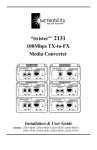
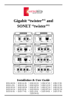
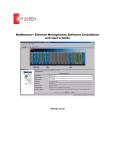
1
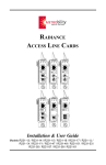
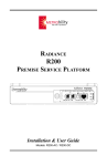
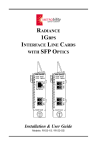
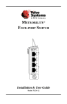
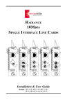
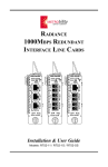
RADIANCE
DIN RAIL MOUNTED
CHASSIS
Installation & User Guide
Model: RD20-24
Radiance Series
Chassis:
RD20-24 ______ 2-slot DIN rail chassis with DC power
R5000-17HS ___ 17-slot 2U chassis with AC or DC power
R1000-xxx _____ 2-slot 1U chassis with AC and/or DC power
R400-2HS-1A __ 2-slot chassis with external AC power
R200-xx _______ 1-slot chassis with AC or DC power
The following is a listing of additional products in the Metrobility Radiance series.
Refer to each product’s specific installation and user guide for operational
features.
Line Cards:
10 Mbps
Copper to coax
Copper to fiber
Redundant
10/100 Mbps
Copper to copper
Copper to fiber
Fiber to fiber
Chassis stacking
Access
SONET
Fiber to fiber
100 Mbps
Copper to fiber
Fiber to fiber
Redundant
Access
Gigabit
Fiber to fiber
Copper to fiber
Redundant
T1/E1
Copper to fiber
T3/E3
Copper to fiber
Management:
R502-M _______ Management card with dual Ethernet interfaces and
embedded WebBeacon management software
NetBeacon® ____ Element and service provisioning management software
This publication is protected by the copyright laws of the United States and other countries, with all rights
reserved. No part of this publication may be reproduced, stored in a retrieval system, translated,
transcribed, or transmitted, in any form, or by any means manual, electric, electronic, electromagnetic,
mechanical, chemical, optical or otherwise, without prior explicit written permission of Metrobility Optical
Systems, Inc.
© 2003-04 Metrobility Optical Systems, Inc.
All rights reserved.
Printed in USA.
Table of Contents
Radiance DIN Rail Mounted Chassis Installation & User
Guide
Overview .............................................................................................................. 4
Installation Guide ............................................................................................... 6
Unpack the Chassis and Accessories ..................................................... 6
Remove Protective Film ......................................................................... 6
Mount the Chassis .................................................................................. 7
Install the Line Cards ............................................................................. 8
Connect to the Network ......................................................................... 9
Apply Power to the Chassis ................................................................. 10
User Guide ......................................................................................................... 11
Management Line Card ........................................................................ 11
Line Cards ............................................................................................ 11
Topology Solutions .............................................................................. 12
Technical Specifications ....................................................................... 14
Abbreviations and Acronyms ............................................................... 15
Product Safety, EMC and Compliance Statements .............................. 16
Warranty and Servicing ........................................................................ 17
Metrobility, Metrobility Optical Systems, and NetBeacon are registered trademarks of Metrobility Optical
Systems, Inc. The Metrobility Optical Systems logo is a trademark of Metrobility Optical Systems, Inc. All
others are trademarks of their owners.
The information contained in this document is assumed to be correct and current. The manufacturer is
not responsible for errors or omissions and reserves the right to change specifications at any time
without notice.
Overview
The Radiance DIN Rail Mounted Chassis is a two-slot, dual DC powered
chassis ideal for industrial and automation applications which may be migrating
to Optical Ethernet. The chassis, which operates between -20º and 70ºC, is
convection cooled and requires no fans. Its two redundant 24-volt DC power
inputs ensure nonstop operation. If one power supply fails, the other
automatically provides the entire power load for the unit.
Designed for maximum flexibility, the DIN rail chassis can be customized with
any combination of Metrobiltiy’s wide range of media conversion line cards that
support interfaces at 10, 100, and 1000 Mbps; T1/E1, T3/E3, SONET OC-3/
STM-1, and OC-12/STM-4; and redundant data paths at 10, 100, and 1000
Mbps. The chassis also supports a management card and a four-port 10/100
Mbps switch. Depending on the model, diagnostic features such as Remote
Loopback, Link Loss Carry Forward, Link Loss Return, Auto-Recovery, and Far
End Fault are available on the cards.
To increase reliability and reduce troubleshooting time, Metrobility offers
several management options. The SNMP management card collects a variety of
network data and link information including the chassis’s voltage and
temperature. For Web-based management of the DIN rail chassis using a
standard Web browser, Metrobility provides the WebBeacon kernel embedded
into the management card. NetBeacon® element management software provides
proactive management support including automatic e-mail notification.
Metrobility’s DIN rail chassis provides seamless connectivity with all major
switch and router manufacturers and offers a robust and versatile solution for
fiber connectivity in any industrial environment.
The Radiance DIN rail mounted chassis provides the following key features:
• Redundant 24-volt DC power inputs with screw-down terminal blocks.
• Passive convection cooling with no rotating mechanical parts such as
fans.
• Modular design to fit any two Metrobility single-slot line cards, or one
double-slot redundant interface line card.
• Optional management card for easy troubleshooting and SNMP management using NetBeacon software or any SNMP application.
4
Overview
• Fast and easy installation compliant with DIN 46 277 and DIN EN 50 022
mounting specifications.
• Rugged industrial enclosure with bright zinc chromate finish.
Related Documentation
Refer to the enclosed documentation CD-ROM or go to Metrobility’s website
(www.metrobility.com/support/manuals.htm) to view product manuals for the
Radiance series.
Radiance DIN Rail Mounted Chassis
5
Installation Guide
Follow the simple steps outlined in this section to install and start using the
Radiance DIN Rail Mounted Chassis.
NOTE: Electrostatic discharge precautions should be taken when handling any
line card. Proper grounding is recommended (i.e., wear a wrist strap).
1
Unpack the Chassis and Accessories
Check that the following components have been included:
• Radiance DIN rail mounted chassis
• CD-ROM
The following items are available separately:
• NetBeacon software
• Line cards
• Management card
Your order has been provided with the safest possible packaging, but
shipping damage does occasionally occur. Inspect it carefully. If you
discover any shipping damage, notify the carrier and follow their
instructions for damage and claims. Save the original shipping carton if
return or storage of the unit is necessary.
2
Remove Protective Film
A clear protective film covers the sides of the chassis. Lift up an edge
and peel off the plastic film from both sides.
1
6
Installation Guide
2
3
Mount the Chassis
A clip is provided on the back of the chassis for mounting onto a DIN
rail.
DIN Rail Clip
+
+
Rear View
To mount the chassis, hook it onto the DIN rail with the top of the clip,
as shown below. The chassis will hang down.
Push to
Snap in Place
DIN Rail
Gently push the chassis toward the rail to snap it in place. A “click”
sound verifies that the attachment is secure.
Radiance DIN Rail Mounted Chassis
7
4
Install the Line Cards
The Radiance DIN rail mounted chassis supports any two single-slot
interface line card or one double-slot redundant interface line card.
Radiance line cards offer the ease of plug-and-play installation and are
hot-swappable.
Before installing any card, note the following:
• Set all switches and/or jumpers on the line card. Refer to the card’s
user guide for detailed configuration instructions.
• A blank panel is installed in the chassis. Do NOT remove the panel
unless you are installing two line cards. To remove the blank panel,
turn the thumbscrew counterclockwise until loosened.
Follow the simple steps outlined below to install a line card:
• Grasp the card by the front panel as shown.
• Line the edges of the board with the top and bottom card guides, and
slide the card in until the edges are flush and even with the front of
the unit. Do not force the card into the slot. It should slide in easily
and evenly.
• Secure to the chassis by turning the thumb screw clockwise until
snug. The line card is now ready for connection to the network.
Blank
Panel
Card
Guide
1000 BASE
PWR
LK
1
AT
R
X
LK
2
T
X
1
IMPORTANT!
Tighten thumb screw
to secure each card firmly
to chassis before making
network connections.
8
Installation Guide
AT
5
Connect to the Network
Connecting the Line Cards
To connect the individual line cards to the network, refer to their
corresponding installation and user guides.
Connecting the Management Line Card
If a management line card is installed in your chassis, follow the
procedure below to connect to the network. The management line card
supports 10Base-T Ethernet.
• Using a standard Category 3 or 5 UTP cable, connect Port 1 on the
management card to your network. Although the two Ethernet ports
can be configured for either full or half duplex, half duplex is
recommended. Refer to the Command Line Interface Reference
Guide for a detailed description of configuration commands.
• Using the supplied null-modem console cable, connect the male DB9 port on the management card to the serial port on your PC.
• For instructions on stacking, refer to the Command Line Interface
Reference Guide.
Radiance DIN Rail Mounted Chassis
9
6
Apply Power to the Chassis
IMPORTANT
• Turn off the DC voltage source before beginning.
• Connect the wire leads to the chassis before applying power.
The DIN rail chassis provides two input power supply connections,
PWR A and PWR B. The two power supplies support redundant power,
however, there is no load distribution. With redundant power, if the
source to PWR A or B fails, the other source automatically provides the
entire power load for the chassis. An input power supply may be
removed or replaced without interrupting chassis operations as long as
the other input is providing power.
Power connectors are located below the front panel of the main housing
unit. The inputs have screw-down terminal blocks that support 24 V
DC at 0.75 A. Connect the chassis only to a UL listed Class “2” or LPS
power source.
24VDC
.75A
CLASS 2
PWR A
—
+ — +
24VDC
.75A
CLASS 2
PWR B
• Connect the wire leads from the voltage source to the appropriate
terminals and tighten the screws. For redundant power, connect each
power supply to a separate power source.
• Verify proper connection and operation using the PWR LED on the
installed card(s).
Caution: The center terminal connector provides grounding for the
chassis and must be maintained.
10
Installation Guide
User Guide
This section contains more information regarding the Radiance DIN Rail
Mounted Chassis.
Management Line Card
The management card is the SNMP agent for the Radiance chassis. Connected
via the backplane to the other line card in the chassis, the management card reports individual board status to Metrobility’s NetBeacon software (version 3.6 or
higher) or any SNMP application. Thus, the network administrator receives immediate information on network operations via a PC. Metrobility also provides
the WebBeacon kernel, embedded into the management card, for Web-based
management via the Internet using browsers such as Netscape® Navigator® or
Microsoft® Internet Explorer. Refer to the Command Line Interface Reference
Guide, NetBeacon Element Management Software Installation & User’s
Guide or WebBeacon Management Software Installation & User’s Guide for
detailed software instructions.
Line Cards
Metrobility’s line cards deliver carrier-class media, speed, and distance solutions
to address the needs of today’s industrial networks. An extensive line of plugand-play, hot-swappable cards support IP/Ethernet interfaces at 10, 100, 1000
Mbps, T1/E1, T3/E3, SONET OC-3/STM-1, and OC-12/STM-4. For missioncritical applications, Metrobility’s redundant interface line cards feature network-on-demand accessibility, reliability, and enhanced security.
Maximum segment lengths are supported on either side of the chassis, and all
signal activity is reliably propagated from one cable to the other assuring
accurate data flow across the network.
Refer to the each line card’s specific installation and user guide for additional
product information.
Radiance DIN Rail Mounted Chassis
11
Topology Solutions
Metrobility’s DIN rail chassis and media conversion line cards support a variety
of industrial and automation applications including:
• Interconnection of Ethernet PLCs, operator interface, and motion control
• Ethernet I/O
• Machine monitoring
• Environmental control
• Test and measurement
• Process control
• Remote data acquisition
• Communications gateway
Basic Copper to Fiber Connectivity
10 Mbps
MDF / IDF
10/100
10BASE
PWR
FD PWR
Office
Ethernet
AUI to RJ-45
Transceiver
LK
AT
RX
T
X
LK
x
II
TX
FL
R
X
M
M
LK
RX
AUI
100
TP
R111
or
R612
R643
CNC, PLC, etc.
LK
AT
T
X
TX
MM
100 Mbps MM or SM Fiber
10/100
RD20-24
Chassis
10 Mbps MM or SM Fiber
10/100 Mbps
CNC, PLC, etc.
Line Protection and Restoration
10/100 Mbps
10/100
Secondary
CNC, PLC, etc.
100 Mbps
MDF / IDF
10/100 BASE
100 BASE
redundant twister “
LK
R
X
T
X
AT
LK
R
X
T
X
LK
2
PRIMARY
AT
1
RX
SW
TX
LK
AT
10/100 Mbps
RX
10/100
PWR
MAIN
PWR
RESET
SECONDARY
CNC, PLC, etc.
3
LK
TX
4
12
User Guide
RD20-24
Chassis
with
R732
RD20-24
Chassis
with
R104
10/100 Mbps
10/100
Primary
100 Mbps MM or SM Fiber
CNC, PLC, etc.
10/100
CNC, PLC, etc.
10/100
Four Port Switch
CNC, PLC, etc.
MDF / IDF
10/100 BASE
100 BASE
PWR
PWR
R133
R104
TP
1
LK
RX
10/100 Mbps
AT
LK
2
TX
FX
100 Mbps
LK
RX
3
LK
AT
TX
MM or SM
Fiber
4
10/100
RD20-24
Chassis
CNC, PLC, etc.
Managed Remote Links
AUI to RJ-45
Transceiver
100 BASE
AUI
MDF / IDF
CNC, PLC, etc.
10/100 BASE
PWR
10/100
PWR
RX
LK
10/100
10/100
100
FD
RX
TX
100
TX
TX
T
X
RX
RX
LK
LK
RX
M
M
LK
RX
M
M
LK
M
M
RX
RX
LK
LK
TX
AT
100
FD
MM
FX
TX
TX
FX
FD
TX
LK
100
FD
TX
PWR
10/100
PWR
100
MGT-10
PWR
FD
100
LK
FD
RX
RX
RX
RX
1
AT
FX
M
M
RX
RX
LK
LK
RX
M
M
LK
TX
T
X
LK
LK
LK
x
II
RX
M
M
LK
x
II
TX
TX
TX
FX
SM
TX
FX
M
M
RX
RX
LK
LK
TX
x
II
LK
1
RX
LK
R104
FX
SM
RX
M
M
LK
TX
FX
LK
2
AT
TX
FX
TX
RX
M
M
TX
TX
TX
FX
TP
LK
LK
2
x
II
LK
TX
BWDM
R231
AT
T
X
T
X
T
X
LK
x
II
FD
FD
RX
T
X
LK
TX
10/100
PWR
100
100
RX
M
M
TX
10/100
10/100
PWR
FL
RX
x
II
PWR
3
4
TX
TX
TX
100
FD
T
X
LK
x
II
AT
LK
LK
RX
LK
T
X
LK
2
TX
10/100
PWR
100
FD
RX
AT
LK
x
II
x
II
T
X
10/100
PWR
TX
100
1
T
X
LK
x
II
10/100
10/100
PWR
LK
RX
RX
T
X
LK
x
II
PWR
FD
RX
T
X
LK
x
II
100
FD
RX
T
X
LK
x
II
10/100 BASE
PWR
100 FD
FD
T
X
LK
TX
PWR
FD
RX
M
M
TX
10/100
PWR
100
FL
FD
x
II
TX
FX
C
O
N
S
O
L
E
10/100 Mbps
RX
A
3
B
LK
AT
R
ER
100 Mbps MM or SM Fiber
TX
10/100
10/100
10/100
PWR
x
II
CNC, PLC, etc.
4
RD20-24
Chassis
10/100 Mbps
10/100
10/100
100
T
X
CNC, PLC, etc.
Radiance DIN Rail Mounted Chassis
13
Technical Specifications
Power
Input: _________________________________ 24 V DC (SELV) ±20%, 0.75 A
Environmental
Operating Temperature __________________________________ -20º to 70º C
Storage Temperature ____________________________________ -30º to 70º C
Relative Humidity _________________________ 5% to 95% non-condensing
Physical Case ___________ 20 Ga CRS (cold rolled steel) exterior construction
_____________ 18 Ga 5052-H32 aluminum interior construction
Dimensions ______________________________ 5.125" D x 3.0" W x 5.125" H
__________________________________ 13 cm x 7.6 cm x 13 cm
Weight _____________________________________________ 1.56 lb, 0.71 kg
14
User Guide
Abbreviations and Acronyms
A
Amps
AUI
Attached Unit Interface
CNC
Computerized Numerical Control
IDF
Intermediate Distribution Frame
I/O
Input/Output
Mbps Megabits per second
MDF Main Distribution Frame
MM
Multimode
PLC
Programmable Logic Controller
PWR Power
SELV Safety Extra Low Voltage
SM
Singlemode
SNMP Simple Network Management Protocol
UTP
Unshielded Twisted Pair
V DC Volts, Direct Current
Radiance DIN Rail Mounted Chassis
15
Product Safety, EMC and Compliance Statements
This equipment complies with the following requirements:
Product Safety
DIN Compliance
• UL
• DIN 43 880
• cUL
• DIN 46 277
• CE
• DIN EN 50 022
Emissions
• FCC Part 15 Class A
• DOC ICES-03 Class A
• EN55022 Class A
• EN55024: 1998
• CE
This product shall be handled, stored and disposed of in accordance with all
governing and applicable safety and environmental regulatory agency requirements.
The following FCC and Industry Canada compliance information is applicable
to North American customers only.
USA FCC Radio Frequency Interference Statement
This equipment has been tested and found to comply with the limits for a Class
A digital device, pursuant to Part 15 of the FCC Rules. These limits are designed
to provide reasonable protection against harmful interference when the equipment is operated in a commercial environment. This equipment generates, uses
and can radiate radio frequency energy, and if not installed and used in accordance with the instruction manual, may cause harmful interference to radio
communications. Operation of this equipment in a residential area is likely to
cause harmful interference in which case the user will be required to correct the
interference at his own expense.
Caution: Changes or modifications to this equipment not expressly approved by
the party responsible for compliance could void the user’s authority to operate
the equipment.
Canadian Radio Frequency Interference Statement
This Class A digital apparatus meets all requirements of the Canadian Interference-Causing Equipment Regulations.
Cet appareil numérique de la classe A respecte toutes les exigences du
Réglement sur le matériel brouilleur du Canada.
16
User Guide
Warranty and Servicing
Three-Year Warranty for the Radiance DIN Rail Mounted Chassis
Metrobility Optical Systems, Inc. warrants that every Radiance DIN Rail
Mounted Chassis will be free from defects in material and workmanship for a
period of THREE YEARS from the date of Metrobility shipment. This warranty
covers the original user only and is not transferable. Should the unit fail at any
time during this warranty period, Metrobility will, at its sole discretion, replace,
repair, or refund the purchase price of the product. This warranty is limited to
defects in workmanship and materials and does not cover damage from accident,
acts of God, neglect, contamination, misuse or abnormal conditions of operation
or handling, including overvoltage failures caused by use outside of the
product’s specified rating, or normal wear and tear of mechanical components.
To establish original ownership and provide date of purchase, complete and
return the registration card or register the product online at
www.metrobility.com. If product was not purchased directly from Metrobility,
please provide source, invoice number and date of purchase.
To return a defective product for warranty coverage, contact Metrobility
Customer Service for a return materials authorization (RMA) number. Send the
defective product postage and insurance prepaid to the address provided to you
by the Metrobility Technical Support Representative. Failure to properly protect
the product during shipping may void this warranty. The Metrobility RMA
number must be clearly on the outside of the carton to ensure its acceptance.
Metrobility will pay return transportation for product repaired or replaced inwarranty. Before making any repair not covered by the warranty, Metrobility
will estimate cost and obtain authorization, then invoice for repair and return
transportation. Metrobility reserves the right to charge for all testing and
shipping costs incurred, if test results determine that the unit is without defect.
This warranty constitutes the buyer’s sole remedy. No other warranties, such as
fitness for a particular purpose, are expressed or implied. Under no circumstances will Metrobility be liable for any damages incurred by the use of this
product including, but not limited to, lost profits, lost savings, and incidental or
consequential damages arising from the use of, or inability to use, this product.
Authorized resellers are not authorized to extend any other warranty on
Metrobility’s behalf.
Radiance DIN Rail Mounted Chassis
17
Product Manuals
The most recent version of this manual is available online at
http://www.metrobility.com/support/manuals.htm
To obtain additional copies of this manual, contact your reseller, or call
1.877.526.2278 or 1.603.880.1833
Product Registration
To register your product, go to
http://www.metrobility.com/support/registration.asp
25 Manchester Street, Merrimack, NH 03054 USA
tel: 1.603.880.1833 • fax: 1.603.594.2887
www.metrobility.com
5660-000090 C
2/04