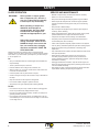
1
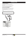
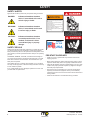
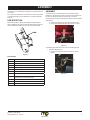
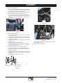
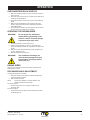
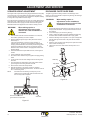
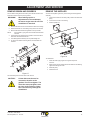
OPERATOR’S AND PARTS MANUAL
Model ZTB
Zero Turn Snowblower
TM
QUALITY YOU CAN SEE, PEOPLE YOU CAN TRUST
M-B Companies, Inc.
1615 Wisconsin Ave.
P. O. Box 200
New Holstein, WI 53061-0200
(920) 898-1560 or 800-558-5800
FAX: (920) 898-4588
Publication: ZTB-080112
11/14/12
Table of contents
introduction...............................................................................................................3
Operator’s Manual..................................................................................................3
Identification Numbers............................................................................................3
safety.............................................................................................................................4
Safety Alerts............................................................................................................4
Safety Decals..........................................................................................................4
Pre-Start Guidelines...............................................................................................4
Operation Guidelines..............................................................................................5
Slope Operation......................................................................................................6
Service And Maintenance.......................................................................................6
ANSI B71.3-1995 Warnings....................................................................................7
controls and features..........................................................................................8
Assembly.......................................................................................................................9
Pre-Inspection.........................................................................................................9
Assembly................................................................................................................9
operation....................................................................................................................13
Checks Before Each Start-Up...............................................................................13
Operating The Snowblower..................................................................................13
Engine Speed.......................................................................................................13
Discharge Angle Adjustment.................................................................................13
Adjustment & Service............................................................................................14
Scraper Height Adjustment...................................................................................14
Discharge Chute Glide Ring.................................................................................14
Remove Ribbon And Gearbox..............................................................................15
Remove The Impeller............................................................................................15
maintenance..............................................................................................................16
Maintenance Schedule.........................................................................................16
storage.......................................................................................................................17
Temporary Storage (30 Days Or Less).................................................................17
Long Term Storage (Longer Than 30 Days).........................................................17
troubleshooting....................................................................................................18
service parts............................................................................................................19
Publication: ZTB-080112
M-B Companies, Inc. 11/14/12
Table of contents
parts List....................................................................................................................20
Snowblower Ribbon..............................................................................................20
Snowblower Chute................................................................................................21
Snowblower Body.................................................................................................22
Decals...................................................................................................................24
Fastener Torque Recommendation.................................................................25
Torque For Standard Fasteners............................................................................25
Torque-Tension Relationship For Metric Fasteners..............................................26
WARRANTY....................................................................................................................27
Publication: ZTB-080112
M-B Companies, Inc. 11/14/12
INTRODUCTION
operator’s manual
You must read, understand and comply with all the safety and
operating instructions in this manual before attempting to set-up and
operate your unit.
Failure to comply with the safety and operating instructions can result
in loss of machine control, serious personal injury to you and/or
bystanders, and risk of equipment and property damage.
identification numbers
When contacting your authorized dealer for information, replacement
parts or service, you MUST have the model and serial number of your
snowblower head and drive unit.
The snowblower head serial number plate/decal can be found in the
location shown in Figure 1. Record the serial number in the space
provided.
Snowblower Serial Number:
Figure 1
Publication: ZTB-080112
M-B Companies, Inc. 11/14/12
3
SAFETY
safety alerts
Signal words and alert symbols notify of important safety precautions.
DANGER!
WARNING!
CAUTION!
Indicates a hazardous situation
which, if not avoided, will result in
serious injury or death.
Indicates a hazardous situation
which, if not avoided, could result
in serious injury or death.
Indicates a hazardous situation
or unsafe practice which, if not
avoided, could result in minor
or moderate injury or property
damage.
safety decals
Reading this manual and the safety instructions it contains will provide
you with the necessary basic knowledge to operate this equipment
safely and effectively. We have also placed several safety labels on the
unit to remind you of this important information while you are operating
your unit.
All DANGER, WARNING, CAUTION, and instructional messages on
your unit should be carefully read and obeyed. Bodily injury can result
when these instructions are not followed. The information is for your
safety and it is important.
These labels will act as a constant visual reminder to you, and others
who may use the equipment, to follow the safety instructions necessary
for safe, effective operation.
If any of these labels are lost or damaged, replace them at once. See
you local dealer for replacements.
WARNING
MOVING PART HAZARD
To prevent serious injury or death from
moving parts:
• Close and secure guards and shields
before starting.
• Keep hands, feet, hair and clothing away
from moving parts.
• Disconnect and lockout power source
before adjusting or servicing.
• Do not stand or climb on machine when
operating.
390-118352
MADE
IN THE
USA
390-140501
PRE-START GUIDELINES
• Install any covers or guards which may have been removed for
shipping purposes.
• Before starting equipment, walk around equipment, making a visual
inspection that all safety devices are properly installed and secured.
• Check that all hardware, fasteners, hydraulic fittings, etc. are in good
condition and properly fastened. Replace any fatigued or damaged
items with proper replacements.
• Personnel who are not required to be in the work area should be
kept away. Never start the equipment unless you are absolutely
certain that everyone in the area is clear of the machine and aware it
is being started.
• Follow the manufacturer’s recommended start-up procedure.
Publication: ZTB-080112
4
M-B Companies, Inc. 11/14/12
SAFETY
operation guidelines
Read, understand and follow all instructions in the manual and on the
unit before starting.
• To avoid serious injury or death, do not modify equipment. Any
modifications made to equipment can be dangerous and can void
equipment warranty.
• Never defeat a safety device to make a task easier.
• Stop engine before: refueling, cleaning, making adjustments or
removing the attachment assembly.
• Follow the drive unit manufacturer’s recommendations for wheel
weights or counter weights.
• Make any adjustments before operating unit.
• Do not touch parts which may be hot from operation. Allow such
parts to cool before attempting to service the unit.
• Always wear proper apparel when operating equipment; safety
glasses, face shield or goggles, ear protection, and dust mask. Tie
hair back. Never wear loose clothing or jewelry that could get caught
in moving parts.
• Before using, always visually check that hardware is present, intact
and secure. Replace worn or damaged parts.
• Never operate equipment with covers or guards removed. Rotating
parts can cause severe injury. Keep hands, feet, hair, jewelry and
clothing away from all moving parts.
• Original purchaser of this unit was instructed by the seller on safe
and proper operation. If unit is to be used by someone other than
original purchaser; loaned, rented or sold, ALWAYS provide this
manual and any needed safety training before operation.
• Only allow responsible adults who are familiar with the instructions,
to operate the unit (local regulations can restrict operator age).
• Never operate the machine with damaged guards, or without safety
protective devices in place.
• Clear the area of objects such as rocks, toys, wire, etc., which could
be picked up and thrown.
• The Operator must understand the functions and parameters of
all controls and how to operate, as well as how to STOP in an
Emergency.
• Be aware of surroundings. Be sure the area is clear of other people,
bystanders or pets. Stop unit if anyone enters the area.
• Do not operate on wet surfaces. Reduced traction could cause
sliding.
• Always look down and behind before and while traveling in reverse.
• Do not shift to neutral and coast down hills.
• Be aware of discharge direction and do not point discharge
at anyone. Do not point the discharge at glass enclosures,
automobiles, or windows.
• Keep children out of the area and under the watchful care of another
responsible adult.
• Always stand clear of the discharge area when operating this unit.
• Never allow children to operate the unit.
• Disengage all clutches and PTO’s before starting engine.
• Use extra care when approaching blind corners, shrubs, trees, or
other objects that may obscure vision.
• Never leave a running machine unattended. Always disengage the
attachment and traction controls, lower the attachment, set the park
brake, stop the engine and remove the ignition key before leaving
the machine.
• Be alert and turn unit off if children enter the area.
NOTE:
All reference to left, right, front, or rear are given from the
operator position and facing forward.
• Operate only in daylight or good artificial light.
• Never carry passengers.
• Do not operate the unit while under the influence of drugs, alcohol or
other medication.
• Watch for traffic when operating near or crossing roadways.
• Use extra care when loading or unloading the unit into a trailer or
truck.
• Keep in mind the operator is responsible for accidents occurring to
other people or property.
• Data indicates that operators, age 60 years and above, are involved
in a large percentage of power equipment-related injuries. These
operators should evaluate their ability to operate the unit safely
enough to protect themselves and others from injury.
• All operators should seek and obtain professional and practical
instruction.
• Protect eyes, face and head from objects that may be thrown from
unit. Wear appropriate hearing protection.
• Always wear substantial footwear and appropriate clothing. Wear
footwear that improves traction on slippery slopes. DO NOT wear
long scarves or loose clothing that could become entangled in
moving parts.
• Abnormal Vibrations are a warning of trouble. Striking a foreign
object can damage unit. Stop unit and engine. Wait for all moving
parts to stop. Inspect unit and make any necessary repairs before
restart.
• Never place your hands or any part of your body or clothing inside or
near any moving part while unit is running.
Publication: ZTB-080112
M-B Companies, Inc. 11/14/12
5
SAFETY
slope operation
WARNING!
Never operate on slopes greater
than 17.6 percent (10°), which is a
rise of 3-1/2 feet (106 cm) vertically
in 20 feet (607 cm) horizontally.
When operating on slopes use
additional wheel weights or
counterweights. See your dealer
to determine which weights are
available and appropriate for your
unit.
Select slow ground speed before
driving onto slope. Travel UP and
DOWN the slope, never across the
face, use caution when changing
directions and DO NOT START OR
STOP ON SLOPE.
Slopes are a major factor related to loss-of-control and tipover
accidents, which can result in severe injury or death. All slopes require
extra caution. If you cannot back up the slope or if you feel uneasy on
it, do not operate on it.
SERVICE AND MAINTENANCE
• Maintain or replace safety and instruction labels as necessary.
• Never run a unit in an enclosed area.
• Keep nuts and bolts tight and keep equipment in good condition.
• Never tamper with safety devices. Check their proper operation
regularly and make necessary repairs if they are not functioning
properly.
• Keep unit free of debris build-up.
• Stop and inspect the equipment if you strike an object. Repair, if
necessary, before restarting.
• Never make adjustments or repairs with the engine running unless
specified otherwise in the engine manufacturer’s manual.
• Components are subject to wear, damage, and deterioration.
• Frequently check components and replace with manufacturer’s
recommended parts, when necessary.
• Check control operation frequently. Adjust and service as required.
• Use only factory authorized replacement parts when making repairs.
• Always comply with factory specifications on all settings and
adjustments.
• Only authorized service locations should be utilized for major service
and repair requirements.
Do
• Never attempt to make major repairs on this unit unless you
have been properly trained. Improper service procedures can
result in hazardous operation, equipment damage and voiding of
manufacturer’s warranty.
• Travel up and down slopes, not across.
• Disengage snowblower and traction, stop the vehicle engine, and
disconnect the spark plug wire(s) before: performing service work or
if the unit vibrates abnormally.
• See your authorized dealer for counterweight recommendations to
improve stability.
• Remove obstacles such as large rocks, tree limbs, etc.
• Watch for holes, ruts, or bumps. Uneven terrain could overturn the
unit. Snow can hide obstacles.
• After striking an object, inspect the machine for damage and make
repairs before restarting and operating the equipment.
• Use slow speed. Tires may lose traction on slopes.
• Choose a low gear so that you will not have to stop or shift while on
the slope.
• Keep all movement on the slopes slow and gradual.
• Do not make sudden changes in speed or direction.
• Always keep unit in gear especially when traveling downhill.
Do Not
• Do not start or stop on a slope. If tires lose traction, disengage the
broom and proceed slowly straight down the slope.
• Do not turn on slopes unless necessary, and then, turn slowly and
gradually downhill, if possible.
• Do not operate near drop-offs, ditches, or embankments. The unit
could suddenly turn over if a wheel is over the edge of a cliff or ditch,
or if an edge caves in.
Publication: ZTB-080112
6
M-B Companies, Inc. 11/14/12
SAFETY
ANSI B71.3-1995 WARNINGS
Training
1. Read the operating and service instruction manual carefully.
Be thoroughly familiar with the controls and the proper use of
the equipment. Know how to stop the unit and disengage the
controls quickly.
2. Never allow children to operate the equipment.
3. Never allow adults to operate the equipment without proper
instruction.
4. Keep the area of operation clear of all persons, particularly small
children and pets.
5. Exercise caution to avoid slipping or falling especially when
operating in reverse.
Preparation
1. Thoroughly inspect the area where the equipment is to be used
and remove all doormats, sleds, boards, wires, and other foreign
objects.
2. Disengage all clutches and shift into neutral before starting
engine (motor).
3. Do not operate the equipment without wearing adequate outer
garments. Wear footwear that will improve footing on slippery
surfaces.
4. Never attempt to make any adjustments while the engine
(motor) is running (except when specifically recommended by
the manufacturer).
5. Let engine (motor) and machine adjust to outdoor temperatures
before starting to clear snow.
6. Always wear safety glasses or eye shields during operation or
while performing an adjustment or repair to protect eye from
foreign objects that may be thrown from the machine.
Operation
1. Do not put hands or feet near or under rotating parts. Keep clear
of the discharge opening at all times.
2. Exercise extreme caution when operating on or crossing gravel
drives, walks, or roads. Stay alert for hidden hazards or traffic.
3. After striking a foreign object, stop the engine (motor), remove
the wire from the spark plug, disconnect the cord on electric
motors, thoroughly inspect the power broom for any damage,
and repair the damage before restarting and operating the
power broom.
4. If the unit should start to vibrate abnormally, stop the engine
(motor) and check immediately for the cause. Vibration is
generally a warning of trouble.
5. Stop the engine (motor) whenever you leave the operating
position, before making any repairs, adjustments, or inspections.
6. When cleaning, repairing, or inspecting make certain the
snowblower and all moving parts have stopped. Disconnect the
spark plug wire and keep the wire away from the plug to prevent
accidental starting.
7. Do not run the engine indoors except for starting the engine or
for transporting the snowblower in or out of the building. Open
the outside doors; exhaust fumes are dangerous.
8. Do not clear snow across the face of slopes. Exercise extreme
caution when changing direction on slopes. Do not attempt to
clear steep slopes.
9. Never operate the snowblower without proper guards plates, or
other safety protective devises in place.
10. Never operate the snowblower near glass enclosures,
automobiles, window wells, drop-offs, and the like without
proper adjustment of the discharge angle. Keep children and
pets away.
11. Do not overload the machine capacity by attempting to clear
snow, at too fast a rate.
12. Never operate the machine at high transport speeds on slippery
surfaces. Look behind and use care when backing.
13. Never direct discharge at bystanders or allow anyone in front of
the unit.
14. Disengage power to the snowblower when it is transported or
not in use.
15. Use only attachments and accessories approved by the
manufacturer (such as wheel weights, counterweights, cabs,
and the like).
16. Never operate the snowblower without good visibility or light.
Always be sure of your footing, and keep a firm hold on the
handles. Walk, never run.
Maintenance and Storage
1. Check shear bolts and other bolts at frequent intervals for
proper tightness to be sure the equipment is in safe working
condition.
2. Never store the machine with fuel in the fuel tank inside a
building where ignition sources are present such as hot water
and spacer heaters, clothes dryers, and the like. Allow the
engine to cool before storing in any enclosure.
3. Always refer to the operator’s guide instructions for important
details if the unit is to be stored for an extended period.
4. Maintain or replace safety and instruction labels as necessary.
5. Run the machine a few minutes after moving snow to prevent
freeze-up of the assembly.
6. Always observe safe refueling and fuel handling practices when
refueling the unit after transportation or storage.
7. Always follow the engine manual instructions for storage
preparations before storing the unit for both short and long term
periods.
8. Always follow the engine manual instructions for proper start-up
procedures when returning the unit to service.
Publication: ZTB-080112
M-B Companies, Inc. 11/14/12
7
controls
INTRODUCTION
and features
The snowblower will discharge snow forward or to either side
depending on the position angle of the discharge chute.
If the chute adjustment is manual:
1. Use the chute rotation control rod to position the discharge
chute.
If the chute adjustment uses the electric actuator:
1. The controls mounted to the handlebar will actuate the
movement of the discharge chute.
2. Press the rocker switch to move.
The lifting and lowering of the attachment may be controlled manually
or electrically.
If the lift/lower is manually controlled:
1. Use the mower deck hand lever to lift/lower.
2. Consult tractor Owner's manual for operation.
If the lift/lower is electrically controlled:
1. Use the electric rocker switch on the handlebar to actuate.
2. Press the rocker switch to lift or lower.
Publication: ZTB-080112
8
M-B Companies, Inc. 11/14/12
INTRODUCTION
Assembly
The ZTB Zero Turn Snowblower is designed to be used with the Zero
Turn Tractor.
Do no make any modifications to the attachment, the mounting frame
or associated hardware. Any modifications may void the equipment
warranty.
Pre-Inspection
Review the list below to identify and validate that all the required
parts and fasteners are present. Contact M-B Companies if items are
missing. Additional fasteners and clips can be purchased locally.
Assembly
The attachment mount should already be mounted to the tractor.
Installation of the attachment mount is described in the publication for
the Zero Turn Attachment Mount to be used with your tractor.
If this tractor will be using the manual lift and swing controls, install the
guide bracket.
a. Position the bracket on top of the front lift assist mount.
b. Use two bolts with washers and nuts to secure it in place.
B
Figure 3
The following steps describe how to mount the snowblower head.
Figure 2
1. Open the attachment pins.
a. Pull out on both pins and rotate to hold them in the out
position.
Loose Parts
QTY
Description
13
Washer, Flat 5/16
12
Nut, Hex 5/16-18 UNC
4
Poly Slide, Lower
4
Poly Slide, Upper
1
Chute Glide Ring
1
Chute Assembly
1
Snowblower Assembly
1
Manual Chute Rotation Assy or
Optional Electric Chute Rotation Assy
2
Poly Skid Shoe for Skid Shoe Install
4
Bolt, 5/16"-18 UNC x 1.50" for Skid Shoe Install
8
Bolt 5/16"-18 UNC x 1.25" for Chute Install
A
Figure 4
Publication: ZTB-080112
M-B Companies, Inc. 11/14/12
9
INTRODUCTION
Assembly
2. Mount the snowblower head.
a. Position the snowblower head to line up with the atttachment
mount. The V-belt should be kept clear of the contact areas.
b. Lower the attachment mount to it's lowest level.
c. Move the tractor forward to engage the top pins in the notch.
d. Lift the attachment mount to the snowblower head.
e. Pull and rotate the lock pins to enable them to spring into
the holes in the snowblower head. Some movement of the
attachment mount may be needed to let the pins spring into
lock position.
I
C
Figure 7
C
E
F
E
Figure 5
3. Install snowblower drive belt.
a. Release the spring tension on the belt tensioner by pushing
in on the tensioner arm.
b. Stretch the V-belt from the snowblower pulley to the bottom
center pulley on the attachment mount. The belt will fit under
the large tension pulley.
c. Loosen the nut and bolt on the bracket that holds the bearing
for the drive belt.
d. Swivel the bearing away from the pulley.
e. At the snowblower drive pulley, route the belt over the flat
pulleys then under the two bottom pulleys. The V-belt must
be positioned narrow side up.
f. Place the V-belt over the snowblower drive pulley.
g. Pull on the tensioner arm to spring load the tension pulley.
h. Swivel the bearing and position it to make contact with the
top (flat side) of the belt.
i. Tighten the bolt and nut to hold the bearing lightly against the
belt. The bearing will keep the drive belt from jumping out of
the pulley.
j. Secure the top cover plate over the pulleys
B
Figure 8
4. To attach the drive belt to the engine, refer to the Attachment
Mount Installation manual.
The snowblower head is now mounted.
Open
To attachment
A
Push in to open.
G Pull out to tension.
Figure 6
Publication: ZTB-080112
10
M-B Companies, Inc. 11/14/12
INTRODUCTION
Assembly
To Assemble the Discharge Chute
Manual (Standard)
a. Place the glide ring on top of the mounting flange. Line up the
bolt holes.
b. Place the discharge chute on top of the glide ring. The teeth
in the plate will mesh with the gear of the manual crank. The
bolt holes must line up.
c. Insert 5/16 carriage bolts through the four pairs of mounting
holes.
g. Mount the bracket for the manual swing controls on the front
lift assist mount. Use two bolts with washers and nuts.
h. The swing control rod will go through the hole of the manual
swing bracket.
i. Attach the plate to the side of the chute opening.
I
B
C
A
Figure 11
Figure 9
d. Position one of the upper slide (narrower) pieces onto the
bolts.
e. Position one of the lower slide pieces onto the bolts.
f. Secure with a flat washer and a locking nut.
D
E
F
Figure 10
NOTE:
The standard discharge chute will have a manual
crank. When the crank is turned, the chute discharge is
redirected. This standard configuration uses a glide ring
as a bearing surface for the chute. Assemble the chute
rotation rod and gear to the body of the snowblower.
Publication: ZTB-080112
M-B Companies, Inc. 11/14/12
11
INTRODUCTION
Assembly
Electric (Optional)
a. Place the glide ring on top of the mounting flange. Line up the
bolt holes.
b. Place the discharge chute on top of the glide ring. the teeth
in the plate will not contact the electric drive. Rotate the chute
so the discharge is facing forward.
c. Place the gear plate for the electric drive over the top of the
chute. Lower it until it is flat and the teeth engage the electric
drive. Some adjustment may be needed to have all the bolt
holes line up. Insert 5/16 carriage bolts through the four pairs
of mounting holes.
H
I
C
B
Figure 14
The assembly is complete.
A
Figure 12
d. Position one of the upper slide (narrower) pieces onto the
bolts.
e. Position one of the lower slide pieces onto the bolts.
f. Secure with a flat washer and a locking nut.
D
E
F
Figure 13
g. When all four slides are installed, the chute should be able to
rotate smoothly but should not be a loose fit.
h. Position the actuator as shown and bolt it to the plate.
i. Attach the plate to the side of the chute opening.
j. Connect the electrical plug to the wiring harness from the
control box mounted to the handlebars.
Publication: ZTB-080112
12
M-B Companies, Inc. 11/14/12
INTRODUCTION
Operation
CHECKS BEFORE EACH START-UP
1. Make sure all safety guards are in place and all nuts, bolts and
clips are secure.
2. Check the engine oil level. See your engine Owner’s Manual for
procedure and specifications.
3. Check the skid shoes to make sure they are set at the desired
height.
4. Make sure that the discharge chute is angled in the proper
direction. See the Service section for adjustment procedures
and troubleshooting.
5. Check the tractor controls for smooth operation. See the tractor
Owner's manual for procedures and operation.
OPERATING THE snowblower
WARNING!
Do not operate the attachment
without working knowledge of the
tractor's controls. Property damage
or personal injury may result.
1. Review the Operator's manual for the tractor.
2. Start the tractor and allow it to warm up. The speed of the
ribbon and discharge impeller are controlled by the speed of the
engine.
3. Refer to the tractor Owner's Manual for proper engagement of
the PTO. Engage the PTO.
4. Move forward to start clearing snow.
WARNING!
The snowblower discharge can
cause property damage and injury
to by-standers. Discharge toward
open areas only.
ENGINE SPEED
Larger amounts of snow are removed as engine speed increases.
Adjust speed as needed.
Discharge ANGLE ADJUSTMENT
To change the angle of the discharge:
1. Slow down or stop forward movement. Rotate the discharge
chute to the direction needed.
2. Move forward as needed.
NOTE:
The top of the deflector is manually adjusted. This
controls the height of the discharge.
For manual systems:
1. Use the swing control rod to change the position of the
discharge chute.
For electric systems:
1. Press the electric rocker switch on the handle bars to position
the discharge chute.
Publication: ZTB-080112
M-B Companies, Inc. 11/14/12
13
Adjustment
INTRODUCTION
and service
Scraper Height Adjustment
Discharge chute glide ring
The height of the scraper blade (cutting edge) will determine the quality
of snow removal. The scraper blade mounting position is fixed and
cannot be adjusted. The position of the skid shoes is adjusted vertically
to change the scraper blade clearance height.
The glide ring provides a sliding surface for the discharge chute
rotation. To clean and lubricate or replace the glide ring, the discharge
chute must be removed.
If the skid shoes are positioned too far down, the scraper blade will not
clear all the snow. If skid shoes are set too high, the scraper blade will
wear and allow the ribbon (auger) to make contact with the ground.
Mismatched skid shoe heights will cause uneaven clearing of snow.
WARNING!
When making repairs or
adjustments, the tractor engine
must be OFF if the snowblower is
connected.
1. Park the tractor with the mounted snowblower on a hard, flat,
level surface; preferably concrete or asphalt.
2. Raise snowblower high enough to allow placement of shims
listed in step 3.
If using the snowblower on gravel or uneven surfaces, a
minimum gap of 1" (25 mm) is recommended to minimize the
scraping of unwanted debris. This will help avoid running gravel
through the snowblower. Allow 1/8" (3 mm) between scraper
blade and hard, smooth surfaces. Use appropriate shims when
adjusting height.
3. Place shims between scraper blade and hard, smooth ground
surface.
4. Lower snowblower onto ground/shims.
5. Shut off the tractor. Remove key from ignition and apply parking
brake.
6. Loosen the two lock nuts and carriage bolts for mounting each
skid shoe.
7. Push the skid shoes downward to make solid contact with the
ground. Tighten all mounting locknuts and bolts.
8. Remove shims from below scraper blade.
9. With the skid shoes on the ground, check the clearance
between scraper blade and ground surface. The ribbon must not
be in contact with ground.
NOTE:
WARNING!
When making repairs or
adjustments on the snowblower,
the tractor engine must be off if the
snowblower is connected.
1. Support the discharge chute. Remove the nuts from all four of
the poly slide hold downs. The poly slides should be removed
and cleaned.
2. Lift the discharge up to remove the glide ring.
3. Clean or replace the glide ring. When reinsalling the glide ring
the bottom side should be lubricated with a spray grease.
4. Place the discharge chute in posiiton. Line up the carriage bolts
with the glide ring and the teeth in the plate with the rotation
drive gear.
5. Place the upper and lower poly slide pieces in place and secure
with a washer and locking nut.
6. Tighten the nuts so the chute rotates smoothly and is not a
loose fit.
Glide Ring
Poly Slides
If the skid shoes are wearing unevenly they can be
switched to the opposite side. When the skid shoes are
worn out they must be replaced.
Remove Nuts
Figure 16
Place shims between the
ground and the scraper blade.
Skid Shoe
Figure 15
Publication: ZTB-080112
14
M-B Companies, Inc. 11/14/12
Adjustment
INTRODUCTION
and service
Remove ribbon and Gearbox
Remove the impeller
The two ribbons and gearbox are held in place with two shafts on the
ends and a bracket on the top of the gearbox.
Access to the impeller is gained by first removing the ribbon/gearbox
assembly.
WARNING!
When making repairs or
adjustments on the snowblower,
the tractor engine must be off if the
snowblower is attached.
1.
Remove the V-belt from the drive pulley. Remove the shear bolt
pulley.
2. Loosen the set screw in the bearing.
3. Pull the impeller out.
1. Remove the bolts at each end that hold the shaft in the bearing.
2. Pull the two shafts out. The bearings may need to be removed.
3. Remove the bolts that hold the gearbox to the top bracket.
NOTE:
If the impeller is going to be removed the brackets will be
removed
4. The shaft from the gearbox to the impeller is connected with a
shear bolt. Remove the shear bolt
5. The ribbon/gearbox assembly can be pulled straight out.
6. To remove the ribbons from the gearbox, the shaft bolts are
removed.
Shear Bolt
Figure 18
Shaft
To reassemble:
Shear Bolt
Bearing
1. Clean the shaft. Apply a light coat of grease to prevent
corrosion.
2. Place spacer over the shaft and insert the shaft into the bearing.
Tighten the bearing set screw.
3. Install the pulley.
4. Install shear bolt.
Figure 17
The reassembly is the reverse order of the removal.
CAUTION!
A shear bolt must be used to
connect the impeller to the
gearbox. Do not overtighten. The
outer tube must not tighten onto
the inner shaft. Failure to follow
this instruction may damage the
snowblower.
Publication: ZTB-080112
M-B Companies, Inc. 11/14/12
15
INTRODUCTION
maintenance
maintenance schedule
Maintenance
Required
Service Interval
Notes
Clean and lubricate
discharge chute glide
ring
Annually - More
often if needed
Use spray grease
Change oil in gear
case
Annually - More
often if needed
Publication: ZTB-080112
16
M-B Companies, Inc. 11/14/12
INTRODUCTION
Storage
TEMPORARY STORAGE
(30 DAYS OR LESS)
Here is a checklist of things to do when storing your unit temporarily or
in between uses:
• Properly clean the unit before storage and remove snow, dirt, debris,
salt, etc. to extend paint life.
• If the unit is power-washed, all lubrication points should be greased
before storage. Refer to MAINTENANCE section.
LONG TERM STORAGE
(LONGER THAN 30 DAYS)
Before you store your unit for the off-season, read the Maintenance
and Storage instructions in the Safety section, then perform the
following steps:
1. Coat all bare metal surfaces with paint or light coat of oil to
prevent rusting.
2. Clean external surfaces.
3. Completely lubricate as outlined in the MAINTENANCE section.
Publication: ZTB-080112
M-B Companies, Inc. 11/14/12
17
Troubleshooting
INTRODUCTION
This section provides troubleshooting and service instructions. Locate
the problem and check the possible cause/remedy in the order listed.
IMPORTANT!
Also, refer to the engine manufacturer’s Owner’s Manual for additional
information.
For problems not covered here, contact your local dealer.
Trouble
Ribbon does not rotate.
Possible Cause
1. Drive belt is slipping.
2. Shear bolt is broken.
3. Engine clutch not engaging.
Excessive vibration.
1. Loose parts or damaged assembly.
Before performing any adjustment or service,
stop the engine and wait for moving parts to
stop. Remove the key. To prevent accidental
starting, disconnect the spark plug wire and
fasten away from the plug.
Remedy
1. Check belt-tighten or replace.
2. Check for jam up in ribbon and impeller.
Replace shear bolt.
3. Check clutch operation. Repair if needed
1. Tighten all hardware. Check rotating parts
for damage. If vibration continues.
Publication: ZTB-080112
18
M-B Companies, Inc. 11/14/12
Service
INTRODUCTION
Parts
Part Number
Description
716-172325
Motor, Chute Rotation
401-172342
Gear, Manual Chute Rotation
401-172272
Skid Shoe Block
401-172265
60" Cutting Edge
401-172334
Chute Glide Ring
600-160526
Drive Shaft Bearing
600-132224
Ribbon Bearing
Please have your serial number (S/N) ready when contacting M-B Co. or an Authorized Dealer for replacement parts or service information.
M-B Co.
website:
1615 Wisconsin Ave.
email:
P.O. Box 200
Phone:
New Holstein, WI 53061-0200
FAX:
www.m-bco.com
[email protected]
800-558-5800 or 920-898-4203
Main 920-898-4588
Attachments 920-898-1085
Brush Dept. 920-898-1082
Publication: ZTB-080112
M-B Companies, Inc. 11/14/12
19
INTRODUCTION
Parts List
Snowblower Ribbon
5
14
7
17
9
8
8
6
16
10
8
5
6
2
11
3
8
15
13
5
1
4
Item
Part Number
1
501-160695
12
Description
Gearboc, Reducer, ZSB
Qty
1
2
311-21000
HHCS .31-18 UNC x 1.000
8
3
311-21250
HHCS .31-18 UNC x 1.250
4
4
311-21500
HHCS .31-18 UNC x 1.500
4
5
341-20000
Washer, Flat - 5/16 STD Zinc PL
24
6
370-126976
Carriage Bolt 5/16-18 UNC x .75
14
7
370-172347
Carriage Bolt 5/16-18 UNC x 1.50
4
8
371-81620
Nut, Hex, ESNA, 5/16-18-UNC
34
9
401-160392
Shaft, Auger
2
10
401-172265
Cutting Edge, 60" ZTB
1
11
401-172272
Block, Skid Shoe, Snowblower, 60"
2
12
410-160644
Auger Weldment, RH, 60" ZSB
1
13
410-160645
Auger Weldment, LH, 60 ZSB
1
14
410-172245
Snowblower, W. U. 60"
1
15
410-172669
Gearbox Mount Bottom
1
16
410-172750
Gearbox Mount Top
1
17
600-132224
Bearing, 3/4" Flangette
2
Publication: ZTB-080112
20
M-B Companies, Inc. 11/14/12
INTRODUCTION
Parts List
Snowblower Chute
14
For Electric Rotation
For Manual Rotation
13
3
16
12
2
10
1
15
Part Number
1
310-11000
7
4
8
Item
5
6
11
4
9
5
Description
HHCS .25-20 UNC x 1.000
Qty
2
2
311-10750
HHCS .25-20 UNC x 0.750
2
3
311-21500
HHCS .31-18 UNC x 1.500
2
4
341-10000
Washer, Flat - 1/4 STD Zinc PL
4
5
371-81299
Nut, Hex, ESNA, 1/4-20 NC
4
6
371-81620
Nut, Hex, ESNA, 5/16-18-UNC
2
7
382-172120
Spring Tension
1
8
401-172342
Gear, Chute Rotation
1
9
401-172343
Plate, Gear Mount, Chute
1
10
401-172466
Plate, Bracket
1
11
401-172653
Rod, Chute Rotation
1
12
401-172654
Rod, Chute Rotation
1
13
401-172755
Plate, Gear, Chute Base
1
14
410-172270
Chute W.U., ZSB
1
15
502-172652
U-Joint, Low-Speed 1/2" Bore, 7/8" DP
1
16
716-172325
Motor, Dorman 742-143
1
Publication: ZTB-080112
M-B Companies, Inc. 11/14/12
21
INTRODUCTION
Parts List
SnowBlower Body
21
20
7
17
6
18
31
10
29
30
8
24
23
22
26
1
25
5
11
37
6
15
16
36
19
34
27
9
15
33
28 12
14
2
3
32
4
13
35
Publication: ZTB-080112
22
M-B Companies, Inc. 11/14/12
INTRODUCTION
Parts List
SnowBlower Body
Item
Part Number
Description
Qty
1
311-10750
HHCS .25-20 UNC x 0.750
4
2
311-22250
HHCS .31-18 UNC x 2.250
1
3
311-31000
HHCS 3/8-16 UNC x 1.000
4
4
311-52000
HHCS .50-13 UNC x 2.000
4
5
341-10000
Washer, Flat - 1/4 STD Zinc PL
4
6
341-20000
Washer, Flat - 5/16 STD Zinc PL
9
7
370-126976
Carriage Bolt 5/16-18 UNC x .75
1
8
370-172288
Carriage Bolt 7/16-20 UNC x 1.50
4
9
370-92047
Carriage Bolt 3/8-16 UNC x 1
1
10
370-92106
Carriage Bolt 5/16-18 UNC x 1.25
8
11
371-169215
Nut, 1/4-20 Clip-On, Tapped Hole
4
12
371-81296
Nut-LK-CTR 1/2-20 UNF
1
13
371-81297
Nut, Hex, ESNA, 3/8-16 UNC
4
14
371-81417
Nut, Hex, ESNA, 1/2-13-UNC
4
15
371-81620
Nut, Hex, ESNA, 5/16-18-UNC
9
16
371-82080
Nut, Hex, ESNA, 7/16-14 UNC
4
17
380-169217
Rivet, 3/16 Pop Aluminum
6
18
384-160444
Knob, Threaded, Female, 5/16-18 UNC
1
19
384-176079
Knob, Phenolic 4 Leg w/ 3/8-16 Insert
1
20
401-160339
Hinge, Deflector Chute
1
21
401-160676
Deflector, Chute
1
22
401-160693
Poly Slide, Lower, Center, Chute
4
23
401-169900
Spacer
1
24
401-172334
Chute Glide Ring
1
25
401-172336
Poly Slide, Upper
4
26
401-172378
Plate, Cover, Mount, ZSB
1
27
401-172554
Spacer, .51 ID .63 OAL
4
28
401-176078
Plate, Roller Bracket
1
29
410-172192
Impeller, 60" ZSB
1
30
410-172245
Snowblower, W.U., 60"
1
31
410-172270
Chute W.U., ZSB
1
32
410-176172
Mount, ZSB Pulleys
1
33
600-176055
Cam Follower Eccentric, 1.25 OD
1
34
505-172610
Pulley, 3.50" Idler
2
35
505-172697
Idler Pulley, Flat
2
36
505-172767
Pulley, 9" O.D., 1" I.D. w/Shear Pin Hole
1
37
600-160526
Bearing, 4-Bolt
1
Publication: ZTB-080112
M-B Companies, Inc. 11/14/12
23
INTRODUCTION
Parts List
Decals
1
Item
3
4
2
Part Number
Description
Qty
1
390-118356
Decal, Grease Point
1
2
390-118349
Decal, Danger, No Riders
1
3
390-118351
Decal, Caution, Read Operator’s Manual
1
4
390-118352
Decal, Warning, Moving Parts Hazard
2
Not Shown
390-117897
Decal, M-B
1
Publication: ZTB-080112
24
M-B Companies, Inc. 11/14/12
Fastener Torque
INTRODUCTION
Recommendation
Torque for Standard Fasteners
FNL
Grade 2
Grade 5
Grade 8
Grade 9
G9
Nominal
Dia.
Threads
per inch
(in.)
Tightening Torque
Tightening Torque
Tightening Torque
Tightening Torque
Lubed
Dry
Plated
Dry
Plain
Lubed
Dry
Plated
Dry
Plain
Lubed
Dry
Plated
Dry
Plain
Lubed
Dry
Plated
Dry
Plain
K = 0.15
K = 0.17
K = 0.20
K = 0.15
K = 0.17
K = 0.20
K = 0.15
K = 0.17
K = 0.20
K = 0.15
K = 0.17
K = 0.20
Unified Coarse Thread Series
1/4
20
49 in-lbs
59 in-lbs
66 in-lbs
76 in-lbs
86 in-lbs
101 in-lbs
107 in-lbs
122 in-lbs
143 in-lbs
126 in-lbs
143 in-lbs
168 in-lbs
5/16
18
101
122
135
157
178
209
221
251
295
259
294
346
3/8
16
15 ft-lbs
18 ft-lbs
20 ft-lbs
23 ft-lbs
26 ft-lbs
31 ft-lbs
33 ft-lbs
37 ft-lbs
44 ft-lbs
38 ft-lbs
43 ft-lbs
51 ft-lbs
7/16
14
24
29
32
37
42
49
52
59
70
61
70
82
1/2
13
37
44
49
57
64
75
80
90
106
94
106
125
9/16
12
53
63
70
82
92
109
115
130
154
135
153
180
5/8
11
73
87
97
113
126
150
159
180
212
186
211
248
3/4
10
129
155
172
200
227
267
282
320
376
331
375
441
7/8
9
125
160
167
322
365
429
455
615
606
633
604
710
1
8
187
225
250
483
547
644
681
722
909
799
905
1065
1-1/8
7
266
319
354
596
675
794
966
1095
1288
1132
1283
1510
1-1/4
7
375
450
500
840
952
1121
1363
1545
1817
1597
1810
2130
1-1/2
6
652
783
869
1462
4657
1950
2371
2688
3162
2779
3150
3706
123 in-lbs
139 in-lbs
164 in-lbs
144 in-lbs
163 in-lbs
192 in-lbs
Fine Thread Series
1/4
28
56 in-lbs
68 in-lbs
75 in-lbs
87 in-lbs
99 in-lbs
116 in-lbs
5/16
24
112
135
150
174
197
231
245
278
327
287
325
383
3/8
24
17 ft-lbs
20 ft-lbs
23 ft-lbs
26 ft-lbs
30 ft-lbs
35 ft-lbs
37 ft-lbs
42 ft-lbs
49 ft-lbs
43 ft-lbs
49 ft-lbs
58 ft-lbs
7/16
20
27
32
36
41
47
55
58
66
78
68
78
91
1/2
20
41
49
55
64
72
85
90
102
120
105
120
141
9/16
18
59
71
78
91
103
121
126
146
171
151
171
201
5/8
18
82
99
110
127
144
170
180
204
240
211
239
281
3/4
16
144
173
192
223
253
297
315
357
420
369
418
492
7/8
14
138
165
184
355
403
474
502
568
669
588
666
784
1
14
210
252
280
542
614
722
765
867
1020
896
1016
1195
1-1/8
12
298
357
397
668
757
890
1083
1227
1444
1269
1439
1693
1-1/4
12
415
493
553
930
1055
1241
1509
1710
2012
1768
2004
2358
1-1/2
12
734
880
978
1645
1865
2194
2668
3024
3557
3127
3544
4169
Torque values for 1/4 and 5/16-in series are in inch -pounds. All other torque values are in foot-pounds
Torque values calculated from formulas T=KDF, where
K = 0.15 for “lubricated” conditions
K = 0.17 for zinc plated and dry conditions
K = 0.20 for plain and dry conditions
D = Nominal Diameter
F = Clamp Load
Publication: ZTB-080112
M-B Companies, Inc. 11/14/12
25
Fastener Torque
INTRODUCTION
Recommendation
Torque-Tension Relationship for Metric Fasteners
Class 4.6
4.6
Class 8.8
8.8
Class 10.9
10.9
10.9
Class 12.9
Nominal
Dia.
Tightening Torque
Pitch
(mm)
Tightening Torque
Tightening Torque
Tightening Torque
Lubed
Dry
Plated
Dry
Plain
Lubed
Dry
Plated
Dry
Plain
Lubed
Dry
Plated
Dry
Plain
Lubed
Dry
Plain
K = 0.15
(ft-lbs)
K = 0.17
(ft-lbs)
K = 0.20
(ft-lbs)
K = 0.15
(ft-lbs)
K = 0.17
(ft-lbs)
K = 0.20
(ft-lbs)
K = 0.15
(ft-lbs)
K = 0.17
(ft-lbs)
K = 0.20
(ft-lbs)
K = 0.15
K = 0.20
3
0.5
0.28
0.32
0.38
0.73
0.82
0.97
1.0
1.2
1.4
1.2
1.6
3.5
0.6
0.44
0.50
0.59
1.1
1.3
1.5
1.6
1.9
2.2
1.9
2.5
4
0.7
0.66
0.74
0.87
1.7
1.9
2.3
2.4
2.7
3.2
2.8
3.8
5
0.8
1.3
1.5
1.8
3.4
3.9
4.5
4.9
5.5
6.5
5.7
7.6
6
1
2.3
2.6
3.0
5.8
6.6
7.7
8.3
9.4
11
9.7
13
6
1.25
2.1
2.3
2.7
5.3
6.0
7.0
7.6
8.6
10
8.8
12
7
1
3.8
4.3
5.0
9.7
11
13
14
16
19
16
22
8
1
5.9
6.6
7.8
15
17
20
22
24
29
25
34
8
1.25
5.5
6.2
7.3
14
16
19
20
23
27
24
31
10
1.25
11
13
15
29
33
39
42
48
56
49
66
10
1.5
11
12
14
28
32
37
40
45
53
47
62
12
1.25
21
23
28
53
60
71
76
86
101
89
119
12
1.5
20
22
26
51
58
68
73
82
97
85
113
12
1.75
19
21
25
49
55
65
70
79
93
81
108
14
1.25
26
29
34
66
75
89
95
106
127
111
148
14
1.5
28
32
37
72
82
96
103
117
138
121
161
14
2
30
34
40
78
88
104
111
126
148
130
173
16
1.5
50
57
67
129
146
171
184
208
245
215
287
16
2
47
53
62
121
137
161
173
196
230
202
269
18
1.5
73
82
97
187
212
249
266
303
357
313
417
18
2.5
65
73
86
167
189
222
239
270
318
279
372
20
2.5
91
104
122
236
267
314
337
382
449
394
525
Clamp load calculated as 75% of the proof load for specified bolts.
All Torque values are listed in foot-pounds
Torque values calculated from formulas T=KDF, where
K = 0.15 for “lubricated” conditions
K = 0.17 for zinc plated and dry conditions
K = 0.20 for plain and dry conditions
D = Nominal Diameter
F = Clamp Load
Publication: ZTB-080112
26
M-B Companies, Inc. 11/14/12
LIMITED WARRANTY
Limited Warranty: Subject to the limitations set forth herein, M-B Companies, Inc. (“M -B”) warrants its products to be free
from defects in material and workmanship for a period of twelve (12) months from the date of delivery of the product to its
original owner, except that the warranty is twelve (12) months solely for the following products: Truck Mounted Pavement
Marking Equipment, Airport Snow Removal Products, Attachment Products, Brushes, MSV Multi-Service Vehicles. Parts
shall have a ninety (90) day warranty. This warranty is not transferable without the written consent of M-B.
Notice: M-B’s obligations under this Limite d Warranty are conditioned on M-B receiving, within the warranty period,
written notice from Buyer specifying the nature of any alleged defect and requesting corrective action by Seller.
Remedies: M-B, at its option, will repair or replace, or provide a credit to Buyer for, defective warranted items. If
requested by M-B, products or parts for which a warranty claim is made shall be returned, transportation prepaid, to M-B’s
factory. Buyer shall not return any product for repair, replacement or credit without M-B’s advance written consent.
Other Manufacturer’s Warran ty: On products furnished by M-B, but manufactured by any other manufacturer, the
warranty of said manufacturer, if any, will be assigned to Buyer, if the said warranty is assignable. However, M-B does
not represent or guarantee that such manufacturer will comply with any of the terms of the warranty of such manufacturer.
Exclusions: Any improper use, operation beyond capacity, or substitution of parts not approved by M-B, or alteration or
repair by others in such a manner as in M-B’s judgment materially and/or adversely affects the product shall void this
warranty. This warranty does not apply to defects caused by damage or unreasonable use while in the possession of the
owner, including but not limited to: failure to provide reasonable and necessary maintenance, normal wear, routine tune
ups or adjustments, improper handling or accidents, operation at speed or load conditions contrary to published
specifications, improper or insufficient lubrication, or improper storage.
Seller manufactures power brooms that mount to many makes and models of equipment. Seller attempts to ensure that
the mounting frames fit correctly. However, the large number of tractor models, types and options currently available,
compounded by frequent manufacturer design changes, may prevent Seller from supplying a frame that fits every unit
correctly. Therefore, unless Buyer supplies drawing which detail the attachment points on the specific unit to which the
broom will be mounted, Seller will not be responsible for the fit of the mounting frame.
The batteries, tires, rubber material, brushes and material normally consumed in operation, and major components such
as engines, air compressors, and hydraulic pumps and motors are excluded from this warranty but may be covered to the
extent of any warranty received by M-B from its supplier if permitted by the terms of such warranty.
Limitations of liability: M-B shall not be liable for any incidental, consequential, punitive or special damages of any kind,
including, but not limited to, consequential labor costs or transportation charges in connection with the repair or
replacement of defective parts, or lost time profits or expense which may have accrued because of said defect.
M-B disclaims all other warranties, whether express or implied, including but not limited to any implied warranty of
merchantability or fitness for a particular purpose. This warranty is exclusive remedy of buyer. This warranty cannot be
extended, broadened or changed in any respect except in writing by an authorized officer of M-B.
Notwithstanding anything in this warranty is to the contrary, in no event shall M-B’s total liability hereunder exceed
purchased price of the particular product.
M-BCompanies,
Companies,Inc.
Inc.11/14/12
Copyright 2011
M-B
the
M-B Companies, Inc.
1615 Wisconsin Ave.
P. O. Box 200
New Holstein, WI 53061-0200
(920) 898-1560 or 800-558-5800
FAX: (920) 898-4588