1
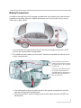
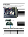
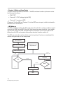
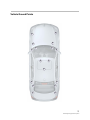
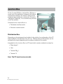
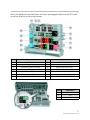
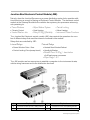
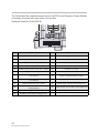
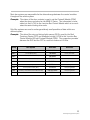
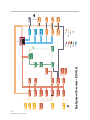
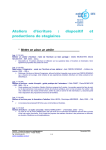
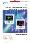
Table of Contents
E90 Voltage Supply & Bus Systems
Subject
Page
Vehicle Electrical System . . . . . . . . . . . . . . . . . . . . . . . . . . . . . . . . . . . . . .4
Introduction . . . . . . . . . . . . . . . . . . . . . . . . . . . . . . . . . . . . . . . . . . . . . . . . . . . .4
Battery Connections . . . . . . . . . . . . . . . . . . . . . . . . . . . . . . . . . . . . . . . . . . . .5
Rear Power Distribution . . . . . . . . . . . . . . . . . . . . . . . . . . . . . . . . . . . . . . .6
Battery Safety Terminal . . . . . . . . . . . . . . . . . . . . . . . . . . . . . . . . . . . . . . .7
Intelligent Battery Sensor (IBS) . . . . . . . . . . . . . . . . . . . . . . . . . . . . . . . .8
IBS Measuring /Evaluation Function . . . . . . . . . . . . . . . . . . . . . . . .10
Servicing the IBS . . . . . . . . . . . . . . . . . . . . . . . . . . . . . . . . . . . . . . . .11
IBS Diagnosis . . . . . . . . . . . . . . . . . . . . . . . . . . . . . . . . . . . . . . . . . . .11
Voltage Measurement . . . . . . . . . . . . . . . . . . . . . . . . . . . . . . . . . . . .11
Current Measurement . . . . . . . . . . . . . . . . . . . . . . . . . . . . . . . . . . . .11
Terminal 15 Wake-up Signal Faults . . . . . . . . . . . . . . . . . . . . . . . .12
IBS Wake-up . . . . . . . . . . . . . . . . . . . . . . . . . . . . . . . . . . . . . . . . . . . .12
Vehicle Ground Points . . . . . . . . . . . . . . . . . . . . . . . . . . . . . . . . . . . . . . . . .13
Junction Box . . . . . . . . . . . . . . . . . . . . . . . . . . . . . . . . . . . . . . . . . . . . . . . .16
Distribution Box . . . . . . . . . . . . . . . . . . . . . . . . . . . . . . . . . . . . . . . . . . . . . . .16
Junction Box Electronic Control Module (JBE) . . . . . . . . . . . . . . . . . . . .19
Bus Systems . . . . . . . . . . . . . . . . . . . . . . . . . . . . . . . . . . . . . . . . . . . . . . . .22
K-Bus . . . . . . . . . . . . . . . . . . . . . . . . . . . . . . . . . . . . . . . . . . . . . . . . . . . . . . . .26
K-Bus (protocol) . . . . . . . . . . . . . . . . . . . . . . . . . . . . . . . . . . . . . . . . . . . . . .26
LIN-Bus . . . . . . . . . . . . . . . . . . . . . . . . . . . . . . . . . . . . . . . . . . . . . . . . . . . . . .26
BSD . . . . . . . . . . . . . . . . . . . . . . . . . . . . . . . . . . . . . . . . . . . . . . . . . . . . . . . . .26
Terminating Resistors . . . . . . . . . . . . . . . . . . . . . . . . . . . . . . . . . . . . . . . . . .26
MOST Bus . . . . . . . . . . . . . . . . . . . . . . . . . . . . . . . . . . . . . . . . . . . . . . . . . . .27
Light Direction . . . . . . . . . . . . . . . . . . . . . . . . . . . . . . . . . . . . . . . . . . . . . .28
Fiber Optics Connector . . . . . . . . . . . . . . . . . . . . . . . . . . . . . . . . . . . . . .29
Identification of Fiber Optics Conductors . . . . . . . . . . . . . . . . . . .29
Diagnosis Information . . . . . . . . . . . . . . . . . . . . . . . . . . . . . . . . . . . . . . .30
Data Flow Interruption . . . . . . . . . . . . . . . . . . . . . . . . . . . . . . . . . . . .30
Overtemperature Shut-Down . . . . . . . . . . . . . . . . . . . . . . . . . . . . . .30
Power Management . . . . . . . . . . . . . . . . . . . . . . . . . . . . . . . . . . . . . . . . . .33
Power Consumption During Operation . . . . . . . . . . . . . . . . . . . . . . . . . . .34
Idle Speed Boost . . . . . . . . . . . . . . . . . . . . . . . . . . . . . . . . . . . . . . . . . . .34
Initial Print Date: 03/05
Revision Date:
Subject
Page
Electric Load Reduction - Engine Running . . . . . . . . . . . . . . . . . . . . .34
Electric Load Cut-Off with Engine Off . . . . . . . . . . . . . . . . . . . . . . . . .35
Terminal 30g Relay (Time-Dependent Deactivation) . . . . . . . . . .36
Terminal 30g_f Relay (Fault-Dependent Deactivation) . . . . . . . .37
Terminal 30 (KL30) . . . . . . . . . . . . . . . . . . . . . . . . . . . . . . . . . . . . . . .39
Terminal 15 (KL15) . . . . . . . . . . . . . . . . . . . . . . . . . . . . . . . . . . . . . . .40
System Diagnosis Information . . . . . . . . . . . . . . . . . . . . . . . . . . . . . . . .41
Closed Circuit Current . . . . . . . . . . . . . . . . . . . . . . . . . . . . . . . . . . . .42
Transport Mode . . . . . . . . . . . . . . . . . . . . . . . . . . . . . . . . . . . . . . . . . . . . .43
Voltage Supply & Bus Systems
Model: E90
Production: From Start of Production
After completion of this module you will be able to:
• Understand the power distribution function
• Explain the Power Management function
• Diagnose current draw situations
• Identify importance of Junction Box
• Understand the vehicles bus structure
3
E90 Voltage Supply & Bus Systems
Vehicle Electrical System
Introduction
The voltage supply system on the E90 uses a Junction Box (JB) with a control module
as a primary power distribution point and bus system gateway. To ensure balanced
energy management in the vehicle an energy management function similar to that used
in the E60 is utilized and is incorporated into the operating software of the DME.
The power supply system in the E90 consists of the following:
Index
1
2
3
4
5
Explanation
Junction Box & Terminal 30 Relays
Junction Box Electronics Control Module
Safety Battery Terminal
Battery, Cables & Grounds
Intelligent Battery Sensor (IBS)
4
E90 Voltage Supply & Bus Systems
Index
6
7
8
9
10
Explanation
Rear Power Distribution Box
DME
CAS
Starter
Alternator
Battery Connections
Located on the right side of the luggage compartment is the battery, from here power is
supplied to the starter, alternator, engine electronics and to the junction box by way of
three main supply cables.
1
2
1. One main cable is routed on the interior of the vehicle along the right side, to the
junction box located behind the glovebox.
2. Two additional main cables run from the B+ terminal underneath the vehicle to the
engine compartment:
Within the battery box are two
transfer points (as shown) for the
two cables that run to the engine
compartment.
The main power cables going to
the engine compartment are
installed/routed (as indicated) in a
protected area underneath the
body of the vehicle.
• One cable goes to the jump start terminal in the engine compartment and then
connects to the starter and alternator.
• The second cable is used to supply power to the engine electronics (DME and
Valvetronics).
5
E90 Voltage Supply & Bus Systems
Rear Power Distribution
Attached directly to the top of the battery is the rear power distribution box which contains the fusible links (non replaceable) used to distribute power to the Junction Box and
Engine Electronics, plus supply power to the Intelligent Battery Sensor (IBS).
Index
Explanation
1
B+ to Starter & Alternator
2
Battery Safety Terminal (BST)
3
Connection from MRS to BST
4
B+ to Engine Electronics
5
B+ for IBS Electronics
6
B+ to Junction Box
7
Intelligent Battery Sensor (IBS)
8
Battery Ground
Index
Explanation
1
Fuses
2
Rear Power Dist. Box Housing
3
Connectors - High Current
Note: The rear power distribution box is only replaceable as a complete unit.
The fuses can not be replaced.
Battery Cables
Cross Section
Material
Line to Starter and Alternator
80 mm2
Aluminum
Line to the Junction Box
2
40 mm
Copper
Line to the Engine Electronics
10 mm2
Copper
6
E90 Voltage Supply & Bus Systems
Battery Safety Terminal
The Battery Safety Terminal (BST) is used to reduce the risk of a short circuit to the B+
terminal of the battery in the event of an accident, as a result of a short circuit on the
cable running from the B+ terminal of the battery to the Starter & Alternator (an
unfused/unprotected circuit) .
Index
Explanation
1
B+ to Starter & Alternator
2
BST Igniter Connection
3
B+ To Rear Power Distribution
4
BST Plastic Housing
5
BST Retaining Spring Clip
6
B+ to Starter & Alternator
7
BST Igniter Signal from MRS
8
B+ Positive Battery Terminal
Depending on the severity of an accident incurred, the MRS control module will provide a
signal to the BST which will disconnect the B+ cable going to the Starter & Alternator. In
the event that the BST is activated, power will continue to be supplied to the rear power
distribution box (a fused/protected power distributor) to allow activation of all other vehicle
systems (such as hazard lights, power locks, power windows, Engine Electronics etc.).
Note: Refer to “ST403 Passive Safety Systems” for more detailed information
on BST operation.
7
E90 Voltage Supply & Bus Systems
Intelligent Battery Sensor (IBS)
The Intelligent Battery Sensor (IBS) as a mechanical/electronic device which is connected
directly to the negative battery terminal.
Index
Explanation
1
Battery Ground Lead
2
B+ Connection for IBS
3
Bit Serial Data Interface (BSD)
4
Intelligent Battery Sensor (IBS)
The IBS contains a micro processor that is used to monitor/measure various battery conditions such as:
• Terminal voltage via measurement from B+ to Gnd
• Charge/discharge current via integrated shunt resistor
• Temperature of battery acid via integrated temp sensor
8
E90 Voltage Supply & Bus Systems
Index
Explanation
1
B+
2
B-
3
Battery Voltage Measurement
4
Battery Temp Measurement
5
Current Measurement
6
Microprocessor
7
BSD
8
DME/ECM
The IBS is able to withstand thermal loads up to 105°C, the chemical effects of the battery acid.
The components of the IBS are shown below:
Index
Explanation
Index
Explanation
1
Copper
4
Injection Molding/Housing
2
Gullwings/Tabs
5
Copper
3
PC Board with Evaluation Electronics
6
*Manganin
*Manganin - Is a copper alloy resistor with a low resistance value, that is able to maintain an extremely
constant temperature regardless of current flow. This material is used as a shunt resistor to
measure current flow by the evaluation electronics component of the IBS.
9
E90 Voltage Supply & Bus Systems
IBS Measuring /Evaluation Function
The measuring/evaluation function of the IBS electronics, continuously measures the following values under all vehicle operating conditions:
• Voltage (6 V to 16.5 V)
• Starting Current (0 A to 1000 A)
• Current (200 A to +200 A)
• Temperature (-40°C to 105°C)
• Closed Circuit Current (0 A to 10 A)
When the vehicle is stationary, the IBS is programmed to wake up every 14 sec. and
makes the required measurements within approx. 50 ms in order to save power.
The measured values from the IBS are provided to the DME by way of the Binary Serial
Data Interface (BSD) to calculate the State of Charge and State of Health for the battery.
• State of Charge (SoC) is a calculated condition showing the current charge of the
battery. SoC is used during key “OFF” periods to insure the battery maintains a sufficient charge to start the engine at least one more time.
• State of Health (SoH) tracks the history of the battery in the vehicle. Charge/discharge cycles and times are monitored. SoH helps the DME determine the proper
charging rates and anticipated battery life. Internal resistance of the battery is calculated by the IBS from the current and voltage dip during engine start. The values are
forwarded to the DME to calculate the SoH of the battery.
Software contained in the microprocessor of the IBS utilizes the measured values to calculate the State of Charge (SoC) of the battery during vehicle sleep mode and compares
this information with that received from the DME/ECM pertaining to the battery SoC/SoH,
during the period of time between engine “OFF” and deactivation of the DME main relay.
The current SoC/battery data is stored in the IBS every 2 hours over a 6 hour time frame,
providing 3 - 2 hour snapshots of battery SoC information. The stored information/snapshot data is overwritten every 6 hours. Whenever KL15 is activated the IBS updates the
DME with the current closed circuit histogram/battery status information, byway of the
BSD. Upon obtaining updated information the DME evaluates the new data and if a
closed-circuit current draw is identified a fault will be stored in the fault memory of the
DME.
10
E90 Voltage Supply & Bus Systems
Servicing the IBS
The IBS is very sensitive to mechanical stress and strain. It is serviced as a complete unit
with the ground cable. The ground cable also serves as a heat dissipater for the IBS.
Particular attention should be paid to the following points in service:
• Do not make any additional connections at the negative terminal of the battery
• Do not modify the ground cable
• Do not make any connections between the IBS and the sensor screw
• Do not use force when disconnecting the ground terminal from the battery
• Do not pull at the ground cable
• Do not use the IBS as a pivot point to lever off the ground terminal
• Do not use the connections of the IBS as a lever
• Use only a torque wrench as described in the repair manual
• Do not release or tighten the sensor screw
IBS Diagnosis
A fault code is stored in the DME when the IBS is defective. The DME adopts a substitute value and assumes IBS emergency mode. IBS emergency mode boosts the idle
speed in order to sufficiently charge the battery.
Direct diagnosis of the IBS is not possible, it can only be diagnosed through the DME.
The self diagnosis function checks the voltage, current, temperature, terminal 15 wake up
signal as well as system errors in the IBS.
Note: The software in the DME and that of the IBS must match. To ensure this requirement it may be necessary to replace the IBS in connection with a software update.
Voltage Measurement
If the IBS is shorted to ground, a DME fault code will display “Voltage Fault DME ON”.
The IBS will be unable to wake up the DME.
If the IBS is shorted to B+, a DME fault code will display “Voltage fault, DME not ON” and
no charging current. The vehicle will NOT enter sleep mode.
Current Measurement
Current measurement is a very dynamic process, indicated by the measuring range of
mA to kA.
The fault code “Current Fault” is entered in fault memory when an implausible value is
determined during the plausibility check of the various measuring ranges of the IBS.
11
E90 Voltage Supply & Bus Systems
Terminal 15 Wake-up Signal Faults
The IBS recognizes wake-up line faults. The IBS can detect a wake-up line error under
the following conditions:
• DME “ON”
• Terminal 15 “ON” (voltage high at IBS)
• Terminal 15 running via BSD
If Terminal 15 at the IBS and Terminal 15 via the BSD are not equal, a fault is indicated in
the BSD line or an IBS Fault.
IBS Wake-up
The IBS constantly monitors the SoC, even when the vehicle is a sleep, a wake-up signal
is sent to the DME via the BSD if the SoC falls below the preset threshold. Upon obtaining the wake-up from the IBS, the DME obtains information on the current SoC of the
battery from the IBS and requests that auxiliary electrical loads be switch off.
The IBS may only wake-up the vehicle once during a key off cycle, once awakened the
vehicle will again return to the sleep mode.
Ignition Off
No Terminal 15
DME sends data to IBS
IBS Monitors current
drop and SoC
DME in Sleep Mode
Without
Auxiliary Loads
With
Auxiliary Loads
SoC
Load Cut-out after
16 minutes
Not OK
Not OK
OK
Wake - Up
DME
12
E90 Voltage Supply & Bus Systems
SoC
OK
X
X
X
X
X
X
X
X
X
X
X
X
X
X
X
X
X
Vehicle Ground Points
13
E90 Voltage Supply & Bus Systems
Classroom Exercise - Review Questions
1.
What components make up the rear power distribution?
2.
What information is recorded by the IBS?
3.
Information from the IBS is transmitted to where? Via what path?
4.
Why does the IBS send a wake-up signal? What module wakes up?
5.
What function does the IBS provide?
14
E90 Voltage Supply & Bus Systems
NOTES
PAGE
15
E90 Voltage Supply & Bus Systems
Junction Box
On the 3 series (E90) the Junction Box (JB) plays a
central role in the distribution of power to the various
components installed in the vehicle. Based on the
equipment level installed in a vehicle the JB may be
“configured” differently. For us vehicles only one variant will be available.
Contained in the Junction Box is a:
• Distribution box/fuse carrier
• Electronic control module
Distribution Box
Depending on the equipment level installed in the vehicle, the configuration of the PC
board installed in the distribution box will vary. Different relays and/or resistors can be
soldered to the board depending on the systems installed on the vehicle.
Integrated into the Junction Box is a PC board which contains soldered on relays for:
• Wiper stage 2
• Horn
• Terminal 30g_f
• Terminal 15
Note: The PC board is not serviceable
16
E90 Voltage Supply & Bus Systems
Within the distribution box itself fuses and relays are plugged directly into the PC board
as well as directly into the wiring harness.
Index
Explanation
Index
Explanation
1
Wiring Harness Connector
8
Relay Secondary Air Pump
2
Horn Relay (PC Board)
9
Internal Interface, Junction Box Control Module
3
Terminal 30 g_f Relay (PC Board)
10
Relay for Rear Window Wiper
4
Terminal 15 Relay (PC Board)
11
Relay for Rear Window Defogger
5
Terminal 30g Relay
12
Relay for Wiper Stage 1
6
Power Supply
13
Relay for Wiper Stage 2 (PC Board)
7
Relay for Windshield Washer
Index
Explanation
1
Junction Box Housing
2
Fuse
3
Wiring Harness Connector
17
E90 Voltage Supply & Bus Systems
The upper left corner of the junction box provides an interface connection directly to the
vehicle wiring harness for the purpose of relay activation and supplying power to various
loads.
Pin
Explanation
Pin
Explanation
1
Secondary Air Pump Activation (Gnd)
6
Activation Term. 30g (Gnd)
2
------
7
Ground
3
Terminal 87, DME Secondary Air Pump
8
------
4
Activation of Electric Fuel Pump, (Gnd)
9
Working current, wiper stage 1
5
Activation Term. 15 (Pos)
10
Working current, wiper stage 2
18
E90 Voltage Supply & Bus Systems
Junction Box Electronic Control Module (JBE)
Not only does the Junction Box serve as a power distribution center it also provides additional functions as a result of having an Electronic Control Module. The electronic control
module is the Gateway Module for the vehicles bus systems, plus processes various signals pertaining to:
• Power Windows
• Climate Control
• Heated Washer Jets
• Wiper Washer System
• Seat Heating
• Relay KL30g_f (Bistable)
• Central Locking
• Mirror Heating
• Instrument Cluster Functions
The Junction Box Electronic control module (JBE) also controls the operation of a number of different relays that are either internal or external to the module.
Relays that are controlled by JBE:
Internal Relays
• Power Window Drive - Rear
External Relays
• Heated Rear Window/Defrost
• Central Locking Drive (except trunk)
• Headlight Washer
• Bistable Term. KL30g_f - deactivation
of off load power consumers
• Wiper Stage 1 & 2
The JBE module use four connectors to establish connection to the instrument cluster,
vehicle wiring harnesses and to the distribution box itself.
Index
1
2
Explanation
Connector X14270 (47 Pin) - Wiring Harness
Connector X4010 (23 Pin) - Power Dist Box
Index
3
4
Explanation
Connector X14271 (54 Pin)Wiring Harness
Connector X14272 (54 Pin) Instrumentation
19
E90 Voltage Supply & Bus Systems
The Distribution Box interface/connection point (X4010) to the Electronic Control Module
is located in the lower left corner of the Junction Box
Interface/Connection Point (X4010):
1
10
11
20
23
Pin
Explanation
Pin
Explanation
1
Diagnosis, Rear Window Defogger
13
Term. 30g_f, switch-on (Gnd)
2
Diagnosis, Rear Window Wiper
14
Activation, Wiper Stage 1 (Gnd)
3
Term. 30_E (Connection is not fuse-protected)
15
Diagnosis, Wiper Stage 1
4
Activation of Rear Window Wiper (Gnd)
16
Activation, Wiper Stage 2 (Gnd)
5
Voltage Supply, Central Locking, Term. 30/F56
17
Activation, Horn (Gnd)
6
Voltage Supply, Central Locking, Term. 30/F57
18
Diagnosis, Wiper Stage 2
7
Voltage Supply, Kombi/OBD socket,
Term. 30/F58
19
Activation, Windshield Washer System
8
Voltage Supply, Steering Column Switch Cluster,
Term. 30/F59
20
Diagnosis, Windshield Washer System
9
Voltage Supply, IHKA, Term. 30/F60
21
Voltage Supply, Left Rear Power Window F64
10
Voltage Supply, Central Information Display,
Terminal 30/F60
22
Voltage Supply, Junction Box Control module F63
11
Term. 30g_f, Switch-off (Gnd)
23
Voltage Supply, Right Rear Power Window F62
12
Activation of Rear Window Defogger (Gnd)
20
E90 Voltage Supply & Bus Systems
Classroom Exercise - Review Questions
Junction Box
1.
What function does the Junction Box serve?
2.
What function does the Junction Box Electronics control module serve?
3.
What relays are soldered to the circuit board?
4.
What systems do the relays on the JBE circuit board impact?
21
E90 Voltage Supply & Bus Systems
Bus Systems
The bus structure in the new BMW 3 Series (E90) builds on the technology being used
in the current models . In the E90 the Junction Box Electronic Control Module (JBE)
serves as the Gateway Module for the bus system, meaning that the JBE is the connection point for the K-CAN, PT-CAN and D-Bus. The Junction box only serves a pass
through function for the F-CAN, data is not transferred by the JB to other systems for
this bus. With the E90 an additional module, the FRM, is connected to the PT-CAN to
receive the brake light signal from the LDM.
As a result of the increase in the inter connecting of control modules some sensors are
no longer connected to the main control module for that system, but rather to the control
module closest to the sensor or actuator and then the information is transferred to the
main controller via the main bus system. By utilizing the closest module as a data transfer point cable length and the number of connectors is reduced.
Within the vehicle two groups of bus systems are used:
• Main bus system (K-CAN, PT-CAN, MOST, F-CAN)
• Sub-Bus system (LIN-Bus, BSD, K-Bus, K-Bus (protocol)
22
E90 Voltage Supply & Bus Systems
Main bus systems are responsible for the data exchange between the control modules
throughout the vehicle system.
Example: The status of the door contacts is read in via the Footwell Module (FRM)
when the doors are locked on the BMW 3 Series. The information is transmitted via the K-CAN to the Junction Box Control Module which in turn activates the central locking drive units.
Sub-Bus systems are used to exchange relatively small quantities of data within one
defined system.
Example: The data of the rain and driving lights sensor (RLS) is read by the Roof
Functions Center (FZD) and forwarded via the K-CAN to the Junction Box
Control Module (JB) and Footwell Module (FRM). The connection provided
between the RLS and the FZD is a sub-bus known as LIN-Bus.
Group
Bus System
Data Rate
Structure
Main
D-Bus (Diagnostic Bus)
10.5/115 Kbit/s
Linear, Single-Wire
Main
K-CAN (Body Bus)
100 Kbit/s
Linear, Two-Wire
Main
PT-CAN (Powertrain-CAN)
500 Kbit/s
Linear, Two-Wire
Main
F-CAN (Chassis CAN)
500 Kbit/s
Linear, Two-Wire
Main
MOST
22.5 Mbit/s
Ring, Fiber Optic
Sub
K-Bus (Body Bus)
9.6 Kbit/s
Linear, Single-Wire
Sub
K-Bus (Protocol Body Bus)
9.6 Kbit/s
Linear, Single-Wire
Sub
LIN-Bus (Local Interconnect Network Bus)
9.6/19.2 Kbit/s
Linear, Single-Wire
Sub
BSD (Bit Serial Data Interface)
9.6 Kbit/s
Linear, Single-Wire
23
E90 Voltage Supply & Bus Systems
24
E90 Voltage Supply & Bus Systems
2x
2x
CA
CAS2
PDC
IHKA
MRS5
CON
CID
FZD
SMFA
USIS
Kombi
FRM
ELV
TAGE
OC3
2x
CDC
TCU
TOP-HIFI
Bus System Overview - E90 U.S.
8x
SH
RLS
SINE
SMC
SBFA
ASP
CCC
RAD2
BSD
MOST
F-CAN
LIN-Bus
K-Bus (protocol)
K-CAN
PT-CAN
K-Bus
WUP
LDM
DSC
AFS
DSC-SEN
LWS
SZL
D-Bus
SDARS
FS
JBE
ACC II
EGS
EKP
DME
IBS
Legend for Bus System Overview - E90 U.S.
Index
Explanation
Index
Explanation
ACC II
Active Cruise Control 2
K-Bus
Body Bus (protocol)
ASPBF
Front Passenger's Side Outside Mirror
K-CAN
Body CAN
ASPFA
Driver's Outside Mirror
KOMBI
Instrument Cluster
CA
Comfort Access
LDM
Longitudinal Dynamics Management
CAS2
Car Access System 2
LIN-Bus
Local Interconnect Network Bus
CCC
Car Communication Computer
MOST
Media Oriented System Transport
CDC
CD Changer
MRS5
Multiple Restraint System 5
CID
Central Information Display
PDC
Park Distance Control
CON
Controller
PT-CAN
Powertrain CAN
D-Bus
Diagnosis Bus
RAD2
Radio 2 (BMW Professional)
DME
Digital motor Electronics
RLS
Rain/Lights Sensor
DSC
Dynamic Stability Control Module
SBFA
Switch Block, Driver's Door
DSCSEN
DSC Sensor
SH
Independent Heating (Seat)
EGS
Electronic Transmission Control Module
SINE
Emergency Current Siren with Integrated Tilt Alarm
Sensor
EKP
Control Module for Electric Fuel Pump
SMCBF
Stepper Motor Controller, Front Passenger
ELV
Electric Steering Lock
SMCFA
Stepper Motor Controller, Driver
F-CAN
Chassis CAN
SMFA
Seat Module, Driver's Side
FRM
Footwell Module
SZL/LWS
Steering Column Switch Cluster/Steering Angle
Sensor
FS
MOST Direct Access
TAGE
Electronic Outer Door Handle Module
FZD
Roof Function Center
TCU
Telematics Control Module
IBS
Intelligent Battery Sensor
TOP-HIFI
Top HiFi Amplifier
IHKA
Automatic Climate Control
USIS
Ultrasonic Passenger-Compartment Sensor
JBE
Junction Box Electronics Control Module
WUP
Wake-up Line
25
E90 Voltage Supply & Bus Systems
K-Bus
The K-Bus serves the purpose of linking the OC3 mat (Seat Occupancy Recognition) to
the MRS 5 Control Module.
K-Bus (protocol)
The term "K-Bus (protocol)" is used for a series of sub-bus systems for various purposes.
The K-Bus protocol used here is a common component used in previous models.
In the E90 this sub-bus is used in connection with the following systems:
• Anti-theft Alarm System (DWA-Bus/K-Bus)
• Connection between MRS5 and TCU
• Electronic Outer Door Handle Module (TAGE) - (CAS-Bus/K-Bus)
• Electromagnetic Steering Wheel Lock (ELV) - (CAS-Bus/K-Bus)
LIN-Bus
The LIN-Bus was used for the first time on the E46 for controlling the outside mirrors.
On the new BMW 3 Series the LIN-Bus is used for the following connections:
• Connection from the FRM to the driver's side switch cluster (19.2 Kbit/s)
• Connection from the RFZ to the RLS (19.2 Kbit/s)
• Driving actuators IHKA (9.6 Kbit/s).
BSD
The bit-serial data interface BSD is also used on the BMW 3 Series for the purpose of
connecting the alternator and the Intelligent Battery Sensor (IBS) to the Engine Control
Module ECM/DME).
Terminating Resistors
Terminating resistors are used to ensure exact data transmission in the bus systems and
are located in the control module of the various bus systems.
Terminating resistors for:
• K-CAN are located in each control module connected to the bus
• F-CAN are located in only two module on the bus (SZL and DSC)
• PT-CAN are located in only two modules on the bus (EKP and DSC)
26
E90 Voltage Supply & Bus Systems
MOST Bus
The new 3 series (E90) uses a MOST-Bus structure, similar to that used on
E60/61/63/64/65/ & E66, as a means of connecting the Information and Communication
Systems (IKT).
MOST is a data bus technology developed & standardized for automotive applications
and stands for Multimedia Oriented System Transport. Devices connected on the MOST
bus use light pulses to communicate/transmit data from one device to the other. The
communication on a MOST-Bus structure is only in one direction around the ring. The
advantage of a MOST-Bus structure over a CAN or LIN-Bus is that it can not only transmit control and sensor data but can transmit digital audio, video signals and transport
graphics as well.
The gateway/master controller on the MOST-Bus is either RAD2 or the CCC depending
on vehicle options installed. The master controller is responsible for data exchange
between the MOST-Bus and the other bus systems as well as retaining the registration
file for the control modules installed on the MOST-Bus.
The registration file stores information regarding the modules installed as well as their
sequence on the MOST-Bus. With the fibre optics connectors, it is possible to connect
control units in the rear area of the BMW 3 Series after a repair in a different order than
they were installed from the factory. The BMW diagnosis system can determine the
installed control units and their order by accessing the information in the registration file.
During the start-up procedure, all control module on the MOST-Bus send their identifier
to the master controller. In this way, the master controller can detect what control modules are connected to the MOST-Bus. A corresponding fault can be set in diagnosis if
the login of one or several control modules is not received.
27
E90 Voltage Supply & Bus Systems
Light Direction
Each control module on the MOST-Bus is able to send data, however it can only be sent
in one direction.
The physical light direction is from the master controller (Rad2 or CCC) to the fibre optics
connector (located in rear of vehicle) and from here to the control modules in the luggage
compartment (CD Changer, Top HiFi Amplifier, TCU, SDARS etc.). From the last control
module, the light returns via the MOST-direct access port to the master controller.
Index
Explanation
Index
Explanation
RAD2
Radio 2
1
Fiber Optics connector
TOP-HIFI
Top HiFi Amplifier
FS
MOST Direct Access (port)
CDC
CD Changer
28
E90 Voltage Supply & Bus Systems
Fiber Optics Connector
The use of a fiber optics connector provides the advantage of being able to easily retrofit
control modules in the area of the luggage compartment. The fibre optics connector is
located behind the left-rear lateral seat back trim panel, next to the rear seat backrest.
A cable duct is provided in addition to the fiber
optics conductor to avoid excessively small radii
(bends) in the fiber optic conductors. The master
controller is always connected in the luggage
compartment, alongside various options.
One or two fiber optic connectors are installed
depending to the equipment configuration. One
fiber optics connector is responsible for the factory-installed control modules. The other fiber
optics connector is used for the installation of
additional options/accessories.
The ends of the fiber optics conductors for
options are always grouped together on the same
row in the fiber optics connector to avoid damage
to the ends of the fiber optics conductors.
As soon as the retrofit is installed, the fiber optics
connectors are reconnected according to instructions and integrated in the MOST-Bus.
Index
Explanation
1
Fiber Optics Connector
2
Installation Aid for Fiber Optic Conductors
Identification of Fiber Optics Conductors
The fiber optics conductors are identified at their ends. The identification indicates
the control unit from which the fibre optics conductor comes or goes.
29
E90 Voltage Supply & Bus Systems
Diagnosis Information
Data Flow Interruption
Several factors can cause an interruption in the data flow in the MOST-Bus:
• Power supply of transmitting control module defective
• Internal fault in transmitting control module
• Transmitter in transmitting control module defective
• Power supply of receiving control module defective
• Internal fault in receiving control module
• Receiver in receiving control module defective
• Break in the fiber optics conductor between transmitting and receiving module
With the ring break diagnosis and the optical test, it is possible to determine whether and
where there is a break or interruption within the MOST-Bus.
Initially for this purpose, the power supply to the control modules in the MOST-Bus is disconnected. When the power supply is switched on again, all control modules send light
to the next control module in the direction of light. The control module that receives no
light at its input stores the node position 0 in its fault code memory. This means the ring
break is between the control module with the node position 0 and the control module
located before it.
The master controller can also be accessed as a check in the case of fault. The master
controller is always connected to the K-CAN and can therefore also be addressed for fault
diagnosis purposes.
Overtemperature Shut-Down
If the internal control module temperature exceeds a certain value (approx. 80°C) the control module is switched off for 10 minutes in order to protect the internal components.
After this time has elapsed, the control module is switched on again and is fully operational. The entire MOST-Bus is shut down if the affected control module is the master
controller (RAD2 or CCC), for all other control modules on the MOST-Bus, only the specific module is switched off if it overheats.
NOTE: Modules located in the area of the luggage compartment such as TCU
or Top HiFi amplifier or SDARS can generate very high temperatures.
In the event of an overtemperature shutdown corresponding fault entries are made in the
fault code memory of the respective control module which can be evaluated with the
BMW diagnosis system.
30
E90 Voltage Supply & Bus Systems
NOTES
PAGE
31
E90 Voltage Supply & Bus Systems
Classroom Exercise - Review Questions
Bus Systems
1.
What module serves as the main gateway?
2.
What module(s) serve as the controller/gateway for the MOST-Bus?
3.
Identify the various bus structures and what role they have.
4.
What are terminating resistors?
5.
Where are the terminating resistors located?
32
E90 Voltage Supply & Bus Systems
Power Management
A power management function some what similar to that used in the E60 is also used in
the E90 to ensure balanced power/energy distribution in the vehicle. The power management functions are incorporated into the software of the Engine Control Module
(ECM/DME).
Index
Explanation
Index
Explanation
1
Engine
5
Junction Box
2
Alternator
6
Electrical Loads
3
Intelligent Battery sensor (IBS)
7
Engine Control Module
4
Battery
Since the IBS is able to provide exact information on the condition of the battery such as
actual battery voltage, current and temperature to the DME, this allows for greater flexibility in regulating loads and also provides additional diagnostic functions with regard to
energy consumption as well.
33
E90 Voltage Supply & Bus Systems
Power Consumption During Operation
During vehicle operation, the mechanical energy of the engine is converted by the alternator into electrical energy and made available to the various electric loads. The electric
loads receive power primarily via the terminal 30g and 30g_f relays located in the junction
box. Certain electric loads are supplied directly by terminal 30 or by terminal R. For
example, the anti-theft alarm system must still remain active when the vehicle is parked.
The calculations necessary for controlling the energy balance take place within the power
management portion of the DME operating program. The power management program
is able to:
• Regulate the idle speed and charging voltage while the engine is running
• Regulate power consumption of electric loads with relatively high power demands or
switch off loads as required.
• Switch-off certain electric loads when the engine is stationary either as a time controlled function via the CAS 2 and the terminal 30g relay or in response to electrical
faults via the engine control, junction box and the terminal 30g_f relay.
• Generate system faults to perform vehicle or battery diagnosis
Idle Speed Boost
Although the alternator may be operating at maximum speed, the idle speed can be
increased by up to 200 RPM as soon as current is drawn from the battery.
Electric Load Reduction - Engine Running
In addition to increasing the idle speed and the specified charging voltage, the output of
various electric loads can be reduced or loads can be switched off in order to reduce the
power consumption in critical situations. The electric loads are shut down only under the
following two conditions:
• Battery charge status in critical range
• Alternator fully utilized
The following measures are implemented if the above conditions occur:
Function
Operation
Control Module
1. Rear Window Defroster
Clocking
IHKA
2. Seat Heating
Stage 2
SM/JB
3. Seat Heating
50%
SM/JB
4. Heater Blower
75%
IHKA
5. Heater Blower
50%
IHKA
6. Mirror Heating
Off
FRM
7. Rear Window Defroster
Off
IHKA
8. Seat Heating
Off
SM/JB
9. Heater Blower
25%
IHKA
34
E90 Voltage Supply & Bus Systems
Electric Load Cut-Off with Engine Off
Certain electric loads may be active although the engine is off and the closed-circuit
current monitoring feature of the power management function is in operation.
The electric loads in the vehicle are divided into the following groups:
– Legally required electric loads (i.e. side lights, hazard warning system)
– Convenience for the customer (i.e radio, telephone)
These electric loads are excluded from the closed-circuit monitoring system in order to
avoid misinterpretation by the power management function, however these electric loads
must log in with the power management function. In turn, the power management function recognizes the activity and accepts the higher power consumption until the systems
are deactivated and these control modules log off with the power management function.
The power management function within in the DME can send a request to switch off
active electric loads in stationary mode depending on the battery charge status and the
start capability limit. As a result of the request, the stationary loads must deactivate their
functions irrespective of the terminal status and must reach their closed-circuit current
within 5 minutes. Legally required electric loads are excluded from this function.
The E90 uses four relays that are installed in the Junction Box, for the purpose of switching off the power supply to the majority of the control modules when the vehicle is in a
stationary status. The four relays are:
• Terminal 30g - Circuit activation by the CAS
• Terminal 30g_f - Circuit activation by the Junction Box control module (JBE)
which monitors the following activities:
– Invalid wake-up procedures within the bus systems
– Events that prevent sleep mode (control units that keep
the bus systems constantly active)
Note: Since the DME constantly reads and evaluates the battery values the
terminal 30g_f relay can also be switched off via a request from the
DME if the start capability limit of the battery is reached.
• Terminal 30 - Circuit Activation by the CAS
• Terminal 15 - Circuit Activation by the CAS
35
E90 Voltage Supply & Bus Systems
Terminal 30g Relay (Time-Dependent Deactivation)
The terminal 30g relay is controlled by
the CAS, which switches off the connected control modules after 30 minutes if
the engine was running for an extended
period. The switch of time is extended to
60 minutes if a telephone system is
installed in the vehicle.
The terminal 30g relay is controlled by
the car access system and supplies
power to the systems indicated below.
Workshop Exercise:
Highlight modules that use
Terminal 30g
Control modules connected to Terminal 30g
36
E90 Voltage Supply & Bus Systems
*Basic radio not available in U.S market
Terminal 30g_f Relay (Fault-Dependent Deactivation)
The Junction box control module controls
the 30g_f terminal, which is primarily a
terminal 30 circuit that is only switched
off if a fault is detected.
A bistable relay is used to control terminal
30g_f by means of two coils, one to open
the circuit and one to close it, each coil is
controlled by the Junction Box control
module. Each coil is supplied directly by
KL.30, the JB control module grounds
the respective coil in order to open or
close the relay. The relay is normally in
the “On” state and supplies KL.30 to two
fuses (17 & 40). The switch status/position of the relay is retained even when no
power is applied.
Workshop Exercise:
Highlight modules that use
Terminal 30g_f
Control modules connected to Terminal 30g_f
37
E90 Voltage Supply & Bus Systems
Terminal 30g_f is switched ON with:
• Vehicle unlocked
• Terminal change from R “Off” to R “On” or terminal 15
• Change in contact status for the trunk, hood or any door
Note: The relay only needs to be switched on if it was previously turned off, otherwise the relay is in the “On” position.
Terminal 30g_f is switched OFF when:
• With terminal R off, the DME detects, via the IBS, that the starting capability limit has
been reached (battery capacity is just enough to start the vehicle).
• After 30/60 minutes of terminal R off, JB detects that control modules are preventing the vehicle from entering the sleep mode.
• With terminal R off, the JB counts more than 30 wake-ups at terminal R.
Once the terminal 30g_f relay has been switched off, one of the switch-on conditions is
necessary in order to switch it on again. If the fault that caused the relay to switch off is
due to a closed-circuit current fault, a fault code is stored in the memory of the junction
Box.
Note: No indication of which module is responsible for the closed-circuit current fault is provided.
38
E90 Voltage Supply & Bus Systems
Terminal 30 (KL30)
A number of control modules are connected to terminal 30 via the junction box.
Workshop Exercise:
Highlight modules that use
Terminal 30 (KL30)
Control Modules Connected To Terminal 30
39
E90 Voltage Supply & Bus Systems
Terminal 15 (KL15)
The only module on the BUS effected by
Terminal 15 relay is the PDC Control
Module.
The terminal 15 relay in the Junction Box
is deactivated by the CAS.
40
E90 Voltage Supply & Bus Systems
System Diagnosis Information
The control modules for the DME/ECM and Junction Box (JB) provide various forms of
information for the purpose of establishing effective system & Battery diagnosis:
DME/ECM stores various data that can be used for energy diagnosis, such as:
• With an IBS installed the last 32 cycles of closed circuit current monitoring data are
stored
• Last registered battery replacement
• Accumulated mileage over past five days
The Junction Box Electronics stores information pertaining :
• Max number of unexpected wake-ups at with Term R within last 5 weeks
• Last 5 control modules that prevented the vehicle from going to sleep, plus mileage
reading for each event
• Driving profile for the past 5 weeks
Since a Terminal 30g_f relay is installed, information pertaining to the cause/reason for
shutting off of terminal 30g_f such as:
• With terminal R off, the DME detects, via the IBS, that the starting capability limit has
been reached (battery capacity is just enough to start the vehicle).
• After 30/60 minutes of terminal R off, JB detects that control modules are preventing the vehicle from entering the sleep mode.
• With terminal R off, the JB counts more than 30 wake-ups at terminal R.
Once the terminal 30g_f relay has been switched off, one of the switch-on conditions is
necessary in order to switch it on again. If the fault that caused the relay to switch off is
due to a closed-circuit current fault, a fault code is stored in the memory of the Junction
Box.
The BMW diagnosis system can access and evaluate this information an facilitate an
assessment of the history values and indicates the most probable cause of the problem.
41
E90 Voltage Supply & Bus Systems
Closed Circuit Current
The closed-circuit current on the E90 is:
• Approx. 22 mA on fully equipped US vehicles.
A check control message is displayed if a closed-circuit current value of 80 mA was
encountered while the vehicle was stationary.
The following diagrams show a typical closed-circuit current progression for the E90 in
connection with the various operating modes of the vehicles electrical system, with vehicle secured and not secured. The actual current values may change depending on the
vehicles equipment level.
Vehicle Secured/Locked
Index
1
2
3
4
5
6
Vehicle Not Secured/Locked
Explanation
Terminal 15 OFF
Terminal R OFF
Vehicle Secured/Locked
Start of Bus Rest Phase
Electric Load Shut-Down (Terminal 30) after 16 Minutes if Vehicle is Not Locked
Terminal 30g OFF (30 Minutes without TCU or 60 Minutes with TCU)
The electric load shutdown terminal 30 (VA) for interior, footwell, reading and vanity mirror
lights is switched off immediately when the vehicle is secured/locked. If the vehicle is not
locked after the engine was running, for an extended time, terminal 30 (VA) is switched
off after 16 minutes. The function is activated by the footwell module.
42
E90 Voltage Supply & Bus Systems
Transport Mode
The following functions are switched off and on in the E90 when vehicle is placed into
transport mode.
Index
Function
Module
Transport
Mode
(O-On/X-Off)
1
Mirror heater (driver's door)
FRM
X
2
Mirror heater (passenger's door)
FRM
X
3
Follow-me-home" lighting "
FRM
X
4
Side light
FRM
X
5
Parking light
FRM
X
6
Interior light
FRM
O
7
Limiting VA/IB time from 16 min to 1 min (interior light, reading light, luggage
compartment light etc.)
FRM
O
8
Rear window roller blind
JB
X
9
Seat heating (driver/front passenger)
JB
X
10
Mirror heating
JB
X
11
Disconnection of bistable relay after coded time
JB
O
12
Radio remote control (including boot lid release) can be used only with bus
active
CAS
O
13
Limiting 30g time from 30 min to 5 min
CAS
O
14
Reducing terminal R active time from 16 min to 2 min, irrespective of operating status of door contact
CAS
O
15
Slide/tilt sunroof
FZD
X
16
Limiting VA/IB time from 16 min to 1 min (interior light, reading light, luggage
compartment light etc.) FRM is master in this case
FZD
X
17
DWA
DWA
X
18
Rear window defogger
IHR/IHKA
X
19
Blower (limited to max. 90 %)
IHR/IHKA
O
20
Compressor
IHR/IHKA
X
21
Auxiliary heater (PTC)
IHR/IHKA
X
22
Independent heating (if planning status)
IHR/IHKA
X
23
Defrost (100 % blower output possible)
IHR/IHKA
O
24
Auxiliary water pump
IHR/IHKA
X
25
Radio control
RAD1
X
26
Car communication computer operation +"master function" (passive)for
deactivation of: radio function, Top HiFi amplifier, audio CD changer, antenna
amplifier
CCC
X
43
E90 Voltage Supply & Bus Systems
Transport Mode Cont.
Index
Function
Module
Transport
Mode
(O-On/X-Off)
27
Radio control master function for deactivation of:
Top HiFi amplifier, telephone
RAD2
X
28
Central information display, function keys
CID
X
29
Controller
CON
X
30
Telematics function
TCU
X
21
Telephone control, prevent wake-up of MOST-Bus
TCU
X
32
Seat heating (driver/front passenger)
SM
X
33
Comfort access, deactivation of TAGE
CA-SG
X
44
E90 Voltage Supply & Bus Systems
Workshop Exercise - Power Management
Identify/Highlight specific control modules related to the following requests.
Identify the control modules located on the terminal 30g circuit. (refer to page 36)
Identify the control modules located on the terminal 30g_f circuit. (refer to page 37)
Identify the control modules located on the terminal 30 (KL30) circuit. (refer to page 39)
45
E90 Voltage Supply & Bus Systems
Classroom Exercise - Review Questions
1.
Under what conditions is the circuit for term.30g_f switched off?
2.
Describe the operation of relay 30g_f. What controls it?
3.
When is terminal 30g switched off?
4.
For U.S. vehicle what should the current draw be in sleep mode? (approx.)
5.
What type of information is stored for battery diagnosis? How is the information
accessed?
46
E90 Voltage Supply & Bus Systems