1
RANGER 9000E
DOWNLOADABLE CONTROL COMMUNICATOR
INSTALLATION MANUAL
TABLE OF CONTENTS
GENERAL DESCRIPTION . . . . . . . . . . . . . . . . . . . . . . . . . . . . . . . . . . . . . . . . . 2
STANDARD AND OPTIONAL PARTS LIST
FEATURE DEFINITIONS
........................... 2
......................................... 3
TERMINAL DRAWING AND SPECIAL NOTES
........................ 4
TERMINAL DESCRIPTION . . . . . . . . . . . . . . . . . . . . . . . . . . . . . . . . . . . . . . . . 5
PROGRAMMING PROCEDURES & EXAMPLES . . . . . . . . . . . . . . . . . . . . 6 - 7
USERS 1-15 ARM/DISARM CODE ENABLING . . . . . . . . . . . . . . . . . . . . . . . . . 8
PHONE NUMBER & ACCOUNT CODE PROGRAMMING . . . . . . . . . . . . 9 - 10
COMMUNICATOR FORMAT SELECTIONS . . . . . . . . . . . . . . . . . . . . . . . . . . 10
AVAILABLE ZONE TYPES . . . . . . . . . . . . . . . . . . . . . . . . . . . . . . . . . . . . . . . . 12
PROGRAMMING THE AUXILIARY OUTPUTS . . . . . . . . . . . . . . . . . . . . 17 - 21
PROGRAMMING FOR PARTITIONS . . . . . . . . . . . . . . . . . . . . . . . . . . . . . . . . 22
SELECTING COMMUNICATOR CODES
. . . . . . . . . . . . . . . . . . . . . . . . . . . . 25
REPORTING USER NUMBERS FOR VARIOUS FORMATS . . . . . . . . . . . . . 27
USERS 16-30 ARM/DISARM CODE ENABLING . . . . . . . . . . . . . . . . . . . . . . . 32
LOCATIONS ACCESSIBLE THRU DOWNLOADING ONLY . . . . . . . . . . . . . . 36
KEYPAD SETTINGS FOR PARTITIONED SYSTEMS . . . . . . . . . . . . . . . . . . . 37
PROGRAMMING WORKSHEETS . . . . . . . . . . . . . . . . . . . . . . . . . . . . . . 38 - 48
APPENDIX 1 . . . . . . . . . . . . . . . . . . . . . . . . . . . . . . . . . . . . . . . . . . . . . . . . . . . 49
APPENDIX 2 . . . . . . . . . . . . . . . . . . . . . . . . . . . . . . . . . . . . . . . . . . . . . . . . . . . 50
APPENDIX 3 . . . . . . . . . . . . . . . . . . . . . . . . . . . . . . . . . . . . . . . . . . . . . . . . . . . 51
TELEPHONE INTERFACE INFORMATION . . . . . . . . . . . . . . . . . . . . . . . . . . . 52
SPECIFICATIONS & WARRANTY . . . . . . . . . . . . . . . . . . . . . . . . . . . . . . . . Back
CADDX CONTROLS, INC.
903-845-6941
General Description
The Caddx Ranger 9000E is a hardwire 16 zone control/communicator that can be expanded to a maximum
of 32 zones. With the 9090 Wireless Receiver, the Ranger 9000E can support up to 100 points of wireless
protection. This control panel provides some of the most versatile, yet easy to use features available for
most security applications today. Each of the 32 zones can be programmed to be one of nine different types
including 24 Hour, Interior Follower, and Day zone. Each zone is individually annunciated and can be
bypassed from the keypad if so enabled. See page 12 for a description of all zone types. Read the User’s
Manual before you begin the installation for the best overall description of how the Ranger 9000E functions.
After installation of the security system, complete the information on page 1 of the User’s Manual and
explain the system operation to all security system owners/operators.
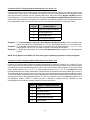
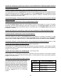
Standard Parts List
The Ranger 9000E is shipped with the parts listed below.
QUANTITY
PARTS DESCRIPTION
PART #
1
MASTER CONTROL PANEL W/O KEYPAD
9000E
1
16.5V 50VA TRANSFORMER
T-1650
18
3.3K ½ WATT E.O.L. RESISTORS
EOL-33
1
4-WIRE FLYING LEAD FOR AUXILIARY OUTPUTS
1
INSTALLATION MANUAL
IM-9000E
1
USER’S MANUAL
OM-9000E
8920
Optional Parts List
The following parts are available for use with the Ranger 9000E.
OPTIONAL PARTS DESCRIPTION
16 LED REMOTE KEYPAD
PART #
9001
LCD ENGLISH LANGUAGE KEYPAD
9060E
DOWNLOADING SOFTWARE PACKAGE
DL-900
PROGRAMMER WITH DIGITAL NUMERIC DISPLAY
8950
16 ZONE EXPANSION SYSTEM
9032
8 RELAY OUTPUT BOARD (HAS SERIAL PRINTER INTERFACE)
9008
16 AUXILIARY OUTPUT BOARD (HAS SERIAL PRINTER INTERFACE)
9016
RANGER WIRELESS RECEIVER
9090
PRINTER INTERFACE CABLE
9017
SMART PROGRAMMER
9075
16 AUXILIARY OUTPUT BOARD (X-10) COMPATIBLE (HAS SERIAL PRINTER INTERFACE)
OPERATOR
9016X
9040
2
FEATURE DEFINITIONS
Alarm Memory - On the 9001, pressing the [0] key and waiting 5 seconds will bring up the last alarm. On the 9060E,
pressing [D] - [0] will access the last 12 alarms, last one first. Pressing the [#] will escape the Alarm Memory Mode.
Automatic Bypass/Instant Arming - When enabled, the control panel can automatically bypass interior follower
zones if an exit is not detected during the delay time, and make the delay zones "Instant" automatically, or by the
pressing the [r] button on the keypad. See location 220, page 17 and locations 412-427, page 31 for the different
combinations of programming this feature.
Chime - This lowest level of security can be enabled by zone (see Locations 171-186, page 13: Assigning Audible
Characteristics For Zones) to create a one second tone through the keypad sounder when the system is disarmed
and a zone is violated. If so programmed, this feature can be turned on and off by a one digit keypress programmed
in location 244, page 22: Assigning The Chime Code.
Dynamic Battery Test - When enabled in locations 254-255, the Ranger 9000E can be programmed to perform
a dynamic battery test for a selected duration, at a selected time. (Refer to page 24.)
Entry-Guard - This unique low level arming mode has been developed to reduce the most common source of false
alarms. When armed in this mode, the opening of any zones designated as "Entry Guard zones" will initiate the
keypad sounder and start a delay before creating an alarm. Non-24 Hour Zones not designated as Entry Guard
Zones will be bypassed. This arming mode will encourage system owners to use their system more frequently when
the premises is occupied. (Refer to locations 155-170, 223, and 396-411, pages 13, 17, and 30.)
Force Arming - When enabled in location 205, the Ranger 9000E can be armed with zones violated, lacking a green
"Ready" light on the keypad. Under this condition, all zones that are not secure at the end of the exit delay will
become bypassed. All zones that become secured before the end of the exit delay will become active in the system.
(Refer to page 14.) NOTE: Bypass capability must be enabled. (See locations 155-170 and 396-411, pages 13
and 30.)
Group Bypass - Zones can be programmed to bypass as a group when the [r] button is pressed during the exit
delay. This feature is enabled in Locations 155-170: Assigning Special Characteristics For Zones, pages 13 and 30.
Internal Event Log - Up to 256 events can be stored in memory along with the date and time of the event. These
events can later be viewed either through downloading or through the 9060E Keypad, and/or sent to an on-site
printer which can be connected to the 9000E through one of the available expansion devices. (Refer to pages 2
and 25.)
New High Powered Siren Driver - This new high powered siren driver is rated at 125db.
Partitions - The Ranger 9000E can be partitioned into a maximum of four separate systems with distinct reporting
codes and user codes per system. (Refer to locations 64-79, 246, 247, and 572-586, pages 8, 23, and 32.)
Ringback - When enabled in location 212, a two second audible output of the siren or bell will occur after either a
closing kissoff is received, upon arming, or at the end of the exit delay. (Refer to page 15.)
Secondary Exit Delay - Used most often for garage doors, this zone type is a second entry/exit delay that has its
own delay times, independent of the standard entry/exit delay zone.
Site Initiated Downloading - Entering [r]-[9]-[8]-[#] from the keypad will initiate a call from the panel to the
download software, if programmed in location 660 (see page 37). If desired, the control panel can be programmed
to automatically call the download software at a specific time. (See location 622, page 35.)
3
4
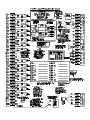
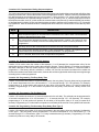
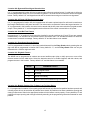
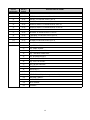
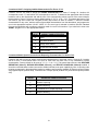
TERMINAL DESCRIPTION
TERMINAL #
DESCRIPTION
1
Connect one side of zone 1 loop. Connect other side of loop to common terminal 2. Open
or short causes alarm.
2
Common (-) Terminal.
3
Connect one side of zone 2 loop. Connect other side of loop to common terminal 2. Open
or short causes alarm.
4 - 12
See Terminal Drawing and repeat the above sequence for zones 3 through 8.
13 - 14
Auxiliary power, regulated 12VDC, maximum 1 AMP.
15 - 26
See Terminal Drawing and continue above described hookup zones 9 through 16.
27 - 28
Auxiliary power, regulated 12VDC, maximum 1 AMP .
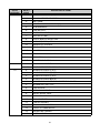
29
Earth Ground, connect to a cold water pipe, or 6 to 10 foot driven rod.
30 - 31
AC input, connect a 16.5V 50VA, Class II U.L. approved transformer (included).
32 - 33
Resettable 12VDC 250mA Aux power.(Memory reset and/or Smoke detector power)
34 -36
Form C programmable on board relay output. Tied to auxiliary output #3.
37
Negative, provided as a convenience for relay connection.
38 - 39
Form A programmable on board relay output. Tied to auxiliary output #4.
40 - 41
Siren driver output to speaker(s). Min speaker rating 30/40 watt at 4, 8, or 16 ohms .
42 - 45
Connect keypad wires as follows; Green to terminal 42, Yellow to terminal 43, Red to
terminal 44, and Black to terminal 45. Maximum run with 22 gauge wire is 200ft, maximum
run with 18 gauge wire is 500ft. Home run cable to each keypad.
T1
House Telephone Tip (Brown).
T
Telephone Tip (Green).
R
Telephone Ring (Red).
R1
House Telephone Ring (Gray).
Battery Leads
Connect to 12VDC lead acid rechargeable battery: Black(-) & Red(+). Do not use a dry cell
battery.
FUSE DESCRIPTION
FUSE #
DESCRIPTION
F1
2 AMP / Auxiliary Power.
F2
3 AMP / Auxiliary Outputs 3 & 4.
F3
3 AMP / Siren Driver.
F4
1 AMP / Keypad and Smoke Detector Power.
5
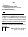
PROGRAMMING
The Ranger 9000E can be programmed by using the 8950 programmer, the 9075 Smart Programmer, the 9060E
LCD keypad, or the 9001 LED keypad. These methods are described below.
Using a Programmer
Plug the optional 8950 programmer into the 4-pin male outlet marked "programer” on the Ranger 9000E PC Board
and the control will enter the program mode. The 8950 will program locations 000 through 635 of the Ranger
9000E, but requires additional care for locations 400 and above. When the 400 location is reached, the two right 7
segment numeric displays will begin to flash on and off, and the left side numeric display will change to "0". The
flashing is a signal to add a 4 to the left side number to determine which location you are now programming. For
example, if you are in location 575, the left (100's column) will be displaying a "1", the middle (10's column) will be
flashing and displaying a "7", and the right (one's column) will be flashing and displaying a "5". By adding a 4 to the
"1" displayed in left column, it is determined that the location number is 575. See "Using the LED Keypad" below.
(When using the 9075 Smart Programmer, please refer to the 9075 Manual.)
Using The LCD Keypad
The most straightforward method of keypad programming is to utilize the 9060E LCD Keypad in the programming
mode. To access the programming mode enter [C]-[0]-[0], followed by the four digit "Go To Program" access code
which is factory default [9]-[0]-[5]-[0] (this code can be reprogrammed), and follow the keypad prompts. NOTE: If the
9000E is partitioned, all partitions must be disarmed to enter the "Program" mode. (See using the LED Keypad
below.)
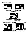
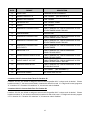
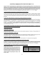
Using The LED Keypad
The 9000E can also be programmed by the standard binary method of keypad programming described below.
However, with over 600 locations, this method will be difficult except for the most experienced programmer. When
the 9001 LED keypad is used for programming, enter the factory default four digit "Go To Program" access code of
[9]-[7]-[1]-[3]. NOTE: The Ranger 9000E must be disarmed to gain access to programming with this code. After entry
of this code, the Ranger 9000E will be in the "Program" mode, and the yellow LED's will display the data in location
000. The data is displayed using a Binary system. With this system the yellow zone 1 LED equals "1" when
illuminated. The zone 2 LED equals "2" when illuminated. The zone 3 LED equals "4" when illuminated. The zone
4 LED equals "8" when illuminated. Thus if the data in location 000 is "9", the LED for zone 1 (=1) and zone 4 (=8)
would be illuminated. By adding the two values together, (1+8=9) you would determine that the data in location 000
is "9". If the data in location 000 is "6", the LED or zone 2 (=2) and zone 3 (=4) would be added (2+4=6) indicating
the data in that location to be "6". If no LED's are illuminated, the location contains a "0". To advance from location
000 through 635, press the [#] key. To go to a specific location, press the location number followed by the [#] key.
The yellow LED's will then display the data in that location. Data is changed by entering a number 0 to 15 followed
by [r] (r = data enter). Review the examples in figure 1 on the following page.
Important Function Codes
There are two function codes that are used in programming the Ranger 9000E and are described below:
[9]-[1]-[0]-[#]
When in the "Program" mode, this function code can be used to write original factory default
codes into the Ranger 9000E, except Locations 636-662.
[9]-[3]-[0]-[#] This function code is used to exit the programming mode after it was accessed via the keypad.
6
7
Locations 000-003: Programming The Master Arm/Disarm Code
Locations 000-003 contain master arm/disarm code (user number 1). Location 000 contains the first digit of the code;
location 003 contains the fourth digit of the code. THE CODE MUST CONTAIN FOUR (4) DIGITS. The master code
can then be used in the RUN mode to enter arm/disarm codes 1-30. The factory default code is [1][2][3][4].
Locations 004-055: Programming The Arm/Disarm Code For Users 2 Thru 14
Locations 004-055 contain the arm/disarm codes for users 2 thru 14. Location 004 contains the first digit of the code
#2, and location 007 contains the fourth digit of code #2. THESE CODES MUST CONTAIN FOUR (4) DIGITS. To
disable a code, PROGRAM a “15" as the first digit of the code. These codes can be changed in the RUN mode using
the master code. Factory default is “15", disabled.
Locations 056-059: Programming The Arm/Disarm Code For User 15 (Duress Code)
Locations 055-059 contain the arm/disarm code for user number 15 (Duress Code). Duress capability is enabled
by programming a communicator code in location 320-323. If locations 320-323 are left unprogrammed, user
number 15 will act as a standard user code. Factory default is “15", disabled.
Locations 060-063: Programming The "Go To Program" Access Code
Locations 060-063 contain the "Go To Program" access code. Location 060 Contains the first digit of the code and
location 063 contains the fourth digit of the code. THE CODE MUST CONTAIN FOUR (4) DIGITS. With the Ranger
9000E disarmed, the "Go To Program" access code can be used to enter the program mode. To disable the "Go To
Program" access code, program a "15" in location 060. The factory default setting is [9][7][1][3]. NOTE: The first digit
of this code should not match the Quick-Arm digit.
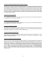
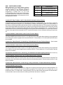
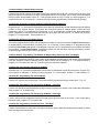
Locations 064-079: Users 1-15 Arm/Disarm Code Enable By Partition
PARTITIONED SYSTEMS
If partitions are utilized, codes may be assigned to a
specific partition by using locations 064-079. This is
done by enabling each individual code (code 1 is
location 064, code 15 is location 079) for each of the
four partitions that code should have access to.
Codes are selected by adding the value for each
partition together and placing that number in the
proper location.
NON - PARTITIONED SYSTEMS
When partitioning is not being utilized, locations
064-079 can be used to control the arming and
disarming authority of the individual arm/disarm
codes. A code can be given limited authority by
programming a number from 1 to 15 in the
corresponding location for that code. Add the values
in the table that correspond to the desired
arm/disarm characteristics, and program the sum in
the appropriate locations.
8
VALUE
PARTITIONS
1
PARTITION 1
2
PARTITION 2
4
PARTITION 3
8
PARTITION 4
VALUE
CHARACTERISTIC
1
STANDARD ARM/DISARM CODE
2
ARM ONLY AFTER CLOSING TIME
4
ARM ONLY CODE
8
OPEN/CLOSE REPORTS FOR USER
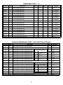
Locations 080-095: Programming Phone #1
Phone #1 is programmed in successive locations beginning with location 080. Delays of four seconds can be
programmed at any point in the phone number by programming a "13" in the appropriate location. Program “11" for
the phone digit “r”. Program “12 for the phone digit “#”. If tone dialing is desired, program a "15" in the location
where tone dialing should begin. If the entire number should be tone dialing, program a "15" in location 080. Factory
default is "14" in each location and the phone number is not enabled. When using split or dual reporting, phone #1
always takes priority over phone #2. A "14" indicates the end of the phone number.
Locations 096-100: Programming The Account Code For Phone #1 (Or Partition One)
The account code sent when phone #1 is dialed is programmed in locations 096-100. If the account code is three
digits long, use locations 096, 097, 098, and program a "0" in locations 099 and 100. If the account code is four
digits long, program a "0" in location 100. If a zero "0" is part of an account code, it should be programmed as a "10".
Program a "0" to indicate the end of the account code. To make this account code the account code for "Partition
One", see location 132.
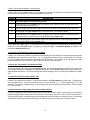
Location 101: Communicator Format For Phone #1
Location 101 contains the communicator format used to transmit to the receiver connected to the phone #1. Consult
the instructions for your central station receiver to determine which format is compatible. Select a format from the
14 listed on page 10. If you require a format other than those listed, review the override options described in
locations 610-615, to build the appropriate format. A "15" must be programmed in location 101 in addition to the
entries into locations 610-615 in order to create a special format. If this location contains a "0", the built-in
communicator will be disabled, and the Ranger 9000E will function as a local only control.
Locations 102-117: Programming Phone #2 (Split or Dual)
Locations 102-117 contain phone #2. This number allows certain communicator reports to go to another number
(split reporting), or to cause the communicator to dial a second number if the primary number does not respond after
the number of attempts programmed into location 133 have been tried unsuccessfully, or for dual reporting. The
same number of attempts are made with the back-up number. Tone dialing and delay instructions are the same as
for the primary number. A "14" indicates the end of the phone number.
Locations 118-122: Programming The Account Code For Phone #2 (Or Partition Two)
Locations 118-122 contain the account code for phone #2. If the account code is three digits long, use locations 118,
119, and 120. If a zero "0" is part of the account code it must be programmed as a "10". Program a "0" to indicate
the end of the account code. If these locations contain a "0", the account code in locations 96-100 will be reported.
To make this account code the account code for "Partition Two", see location 132.
Location 123: Communicator Format For Phone #2
Location 123 contains the communicator format used to transmit to the receiver connected to phone #2. Consult the
instructions for your central station receiver to determine which format is compatible. Select a format from the chart
on page 10. If you require a format other than those listed, review the override options described in locations 610615 to build the appropriate format. A "15" must be programmed in location 123 in addition to the entries into
locations 610-615 in order to create a special format. If this location contains a "0", the format programmed into
location 101 will be selected.
9
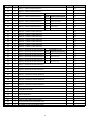
DATA
FORMAT
DESCRIPTION
"0"
LOCAL ONLY
COMMUNICATOR IS DISABLED
"1"
ADEMCO CONTACT ID
DTMF FORMAT
"2"
ADEMCO 4/2 EXPRESS
DTMF FORMAT
"3"
FBI SUPERFAST
DTMF FORMAT 2300Hz
"4"
PAGER
DTMF FORMAT
"5"
RADIONICS EXTENDED SLOW
1800Hz TRANSMITTAL 2300Hz HANDSHAKE 20 PPS
HEX EXTENDED DOUBLE ROUND
"6"
CADDX MODEM
PROPRIETARY
"7"
RADIONICS EXTENDED FAST
1800Hz TRANSMITTAL 2300Hz HANDSHAKE 40 PPS
HEX EXTENDED DOUBLE ROUND
"8"
RADIONICS EXTENDED FAST
1800Hz TRANSMITTAL 1400Hz HANDSHAKE 40 PPS
HEX EXTENDED DOUBLE ROUND
"9"
RADIONICS EXTENDED FAST
WITH PARITY
1800Hz TRANSMITTAL 2300Hz HANDSHAKE 40 PPS
HEX EXTENDED
"10"
UNIVERSAL 4 + 2
1800Hz TRANSMITTAL 2300Hz HANDSHAKE
DOUBLE ROUND 20PPS
"11"
ADEMCO/SILENT KNIGHT SLOW
1900Hz TRANSMITTAL 1400Hz HANDSHAKE 10 PPS
DOUBLE ROUND PARITY
"12"
SILENT KNIGHT 4+2 FAST
1900Hz TRANSMITTAL 1400Hz HANDSHAKE 20 PPS
DOUBLE ROUND PARITY ADD HEX
"13"
SESCOA/FRANKLIN FAST
1800Hz TRANSMITTAL 2300Hz HANDSHAKE 20 PPS
HEX DOUBLE ROUND
"14"
SIA
FSK FORMAT
"15"
OVER-RIDE ENABLE
SEE LOCATIONS 610-615
(SEE APPENDIX 2)
(SEE APPENDIX 1)
Locations 124-127: Account Code Three For Partition #3
Locations 124-127 are utilized to assign an account code for partition #3 if a unique code is desired. If these
locations contain "0", the account code listed in locations 96-100 will be used. If a 3 digit code is used, program a
"0" in location 127. If location 132 contains a "4", this account code is disabled.
Locations 128-131: Account Code Four For Partition #4
Locations 128-131 are utilized to assign an account code for partition #4 if a unique code is desired. If these
locations contain a "0", the account code listed in locations 96-100 will be used. If a 3 digit code is used, program
a "0" in location 131. If location 132 contains a "4", this account code is disabled.
10
Locations 132: Communicator Dialing Sequence 0ptions
The number programmed into this location determines the sequence and method the communicator will utilize when
reporting an event code. Use the table below to build the appropriate number. Add the number(s) associated with
the desired features and program the sum in this location. Factory default is "12" which closely duplicates the
reporting characteristics of our smaller Ranger controls. A "12" is made up of a "4", which ties the account code to
the telephone number, and a "8", which causes the communicator to call phone #1 (Locations 080-095) the number
of attempts listed in location 133 first, and then that same number to the phone #2 (Locations 102-117), if phone #2
is programmed. After the selected number of attempts has been made, the communicator will not take any other
action.
DATA
DESCRIPTION
"1"
Alternate between phone #1 and phone #2 in increments of two calls to each until the selected
number of attempts have been made.
"2"
The communicator attempts the number of calls programmed in location 133 to phone #1, and
if unsuccessful, it will delay 5 minutes and attempt the same number of calls to phone #2, if so
programmed.
"4"
This entry will force the communicator to tie the account code to the phone number.
"8"
The communicator attempts the number of calls programmed in location 133 to phone #1, and
if unsuccessful, the same number of attempts to phone #2, if so programmed.
"0"
If a "0" is entered, the account code corresponds to the partition.
Location 133: Entering The Number Of Dial Attempts
Location 133 is used to enter the number of dial attempts ( 1 to 15 Attempts) the communicator will try for the
appropriate phone number(s) before ending the notification process. Factory default is "8" and the communicator
will make 8 attempts to the first number, and then eight attempts to the second number, if a second number is
programmed. If the factory default is modified in location 132, the first and second numbers will be called at a
minimum the number times listed in this location, however this number might double and the sequence might change
according to the number programmed.
Location 134: Programming The Entry Delay Time
Location 134 contains the number of 10 second increments in the entry delay. The entry delay can be programmed
in 10 second increments from 10 to 150 seconds ("1" = 10 seconds through "15"= 150 seconds). For example,
programming a "2" in this location will produce an entry delay of 20 seconds. (Note: A "0" entry is treated as 0
seconds). Programming a "6" in this location will produce an entry delay of 60 seconds. Factory default is 30
seconds.
Location 135: Programming The Exit Delay Time
Location 135 contains the number of 10 second increments in the exit delay. The exit delay can be programmed in
10 second increments from 10 to 150 seconds ("1" = 10 seconds through "15"= 150 seconds). For example,
programming a "2" in this location will produce an exit delay of 20 seconds. (Note: A "0" entry is treated as 0
seconds). Programming a "6" in this location will produce an exit delay of 60 seconds. Factory default is 60 seconds.
Location 136: Programming The Secondary Entry Delay (Zone Type 7)
Location 136 contains the number of 10 second increments in the entry delay, when an entry delay is initiated by
a zone type 7. This entry delay can be programmed in 10 second increments for 10 to 150 seconds ("1" = 10
seconds through "15" = 150 seconds. (Note: A "0" entry is treated as zero (0) seconds). Programming a "6" in this
location will produce an entry delay of 60 seconds.
11
Location 137: Programming The Secondary Exit Delay (Zone Type 7)
Location 137 contains the number of 10 second increments after arming, before zone trips will be recognized on a
zone type 7. The exit delay can be programmed in 10 second increments from 10 to 150 seconds ("1" = 10 seconds
through "15" = 150 seconds). For example, programming a "2" in this location will produce an exit delay of 20
seconds. (Note: A "0" entry is treated as zero (0) seconds). Programming a "6" in this location will produce an exit
delay of 60 seconds. If the exit delay time in this location is less than, or equal to that in location 135, zone type 7
will be delayed the amount of time programmed in location 135.
Location 138: Programming The Siren Shutdown/Recycle Timeout
Location 138 contains the number of 2 minute increments in the automatic cutoff time. The automatic cutoff time can
be programmed in 2 minute increments from 2 to 30 minutes ("1" = 2 minutes through "15" = 30 minutes). For
example, programming a "2" in this location will produce an automatic cutoff time of 4 minutes. Programming a "6"
in this location will produce an automatic cutoff time of 12 minutes.
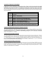
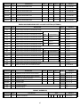
Locations 139-154: Programming The Zone Types For Zones 1-16
Locations 139 through 154 contain a number identifying the characteristics of zones 1 through 16. Location 139
corresponds to zone 1 and location 154 corresponds to zone 16. These zones have been factory defaulted to the
zone type shown in the below chart. Other zone characteristics can be found in the table on the following page.
ZONE #
1
"3" = ENTRY/EXIT DELAY ZONE
2
"5" = INTERIOR FOLLOWER
3-16
DATA
DEFAULT CHARACTERISTICS
"6" = INSTANT
AVAILABLE ZONE TYPES
"1"
DAY ZONE - When armed, a trip produces an instant alarm. When disarmed, a trip activates
the keypad sounder.
"2"
24 HOUR - A trip on a 24 Hour zone produces an instant alarm when armed or disarmed.
"3"
ENTRY/EXIT - A trip will start entry delay. The lack of a trip during exit delay will enable the
Automatic Bypass or Instant mode if so programmed.
"4"
INTERIOR DELAY - A trip on Interior Delay zone will initiate an entry delay. It will be ignored
during exit delay and when disarmed .
"5"
INTERIOR FOLLOWER - Interior zone that follows the delay zones. It is instant during
non-delay times. It can be bypassed before arming, or by allowing it to automatically be
bypassed in the Automatic Bypass/Instant mode if so programmed.
"6"
INSTANT - Produces an instant alarm if tripped when armed. Ignored when disarmed.
"7"
SECONDARY DELAY - Like an Entry/Exit zone but has its own independent delay time.
"8"
FIRE (PRIORITY WHEN AHJ HAS NOT APPROVED) - A short on a FIRE zone (nonbypassable) will communicate to the central station when the Ranger 9000E is armed or
disarmed. An open will create a Trouble condition. Keypad LED will be steady for FIRE, and
flashing for Trouble.
"9"
KEYSWITCH - A zone attached to a momentary keyswitch will cause the Ranger 9000E to arm
or disarm when the zone is shorted. NOTE: Program the corresponding "Special Characteristics
For Zones 1-16"(locations 155-170)as a "0".
12
Locations 155-170: Assigning Special Characteristics For Zones 1-16
Locations 155 through 170 are used to assign zone characteristics for zones 1 through 16. Location 155 is for zone
1 and location 170 is for zone 16. Each zone can have any or all of the following characteristics regardless of the
zone type selected in locations 139-154, excluding Fire zones, which cannot have Bypass Capability enabled.
Factory default is "12" for each of these locations, meaning that Zone Bypass Capability & Entry-Guard is enabled,
and the other characteristics are not enabled. To include other characteristics, add their value, and program the sum
in the appropriate location. See the table below for zone characteristics and their corresponding values.
VALUE
CHARACTERISTIC
1
Fast Loop Response (200mS)
2
Group Bypass Zone
4
Entry-Guard Zone
8
Zone Bypass Capability
Example 1 - To add Group Bypass (Value=2) to Zone Bypass Capability (Value=8) for zone 10 (location 164),
add the value of the two characteristics (2 + 8 ="10"), and program the sum of "10" in location 164.
Example 2 - To enable ALL characteristics for zone 10, add the value of all characteristics (1 + 2 + 4 + 8 = "15"),
and program the sum of "15" in location 164 (zone 10 characteristics location).
Example 3 - To disable all characteristics and create a Non Bypassable Zone, program a "0" in the appropriate
location.
NOTE: Group Bypass zones MUST also have zone bypass capability programmed so they will bypass!
Locations 171-186: Assigning Audible Characteristics For Zones 1-16
Locations 171-186 are used to assign the audible characteristics of each zone 1 through 16. Location 171 is for
zone 1 and location 186 is for zone 16. To determine the appropriate data for these locations, refer to the chart below
and add the sum of the corresponding values to arrive at the correct data for these locations. For all zones except
zone 2, factory default is "13" (1+ 4 + 8 = "13"). Factory default for zone 2 is "5" (1 + 4 = "5"). The Chime feature was
not selected because it is usually undesirable on interior/follower zones which is the factory default type for zone 2.
This means that all 16 zones will create a yelp siren output and a keypad sounder output when an alarm is created.
To select the audible characteristics for any zone, add the values of the audible characteristics from the table below,
and program the sum in the appropriate locations 171-186. If you wish for the zone to be Silent, program a "0" in
the appropriate location. NOTE: If a Fire zone type is selected in locations 139-154, standard fire zone
characteristics will override any selection made for a zone in this section.
VALUE
AUDIBLE CHARACTERISTICS
0
Silent
1
Yelp Siren Audible
2
Steady Siren Audible
4
Keypad Sounder Audible
8
Chime Enable
13
Locations 187-202: Special Communicator Reporting Characteristics For Zones 1-16
Locations 187-202 are used to assign communicator characteristics to individual zones 1 through 16. Location 187
is for zone 1 and location 202 is for zone 16. Each zone can have one or a combination of these characteristics.
Factory default for all zones is "11" (1 + 2 + 8 ="11"). This means that each zone has Restore Reporting (Value=1),
Bypass Reporting (Value=2), and Report Canceling (Value=8) enabled. It should be noted that these locations
are used to enable individual zone report capability by zone. A reporting code must be programmed in the
appropriate location to enable overall reporting capability of Restore reports (location 364), Bypass reports (Location
368), Trouble/24 Hour Tamper reports (location 372), and Cancel reports (location 354).
VALUE
REPORTING CHARACTERISTICS
1
Restore Reporting
2
Bypass Reporting
4
Trouble/24 Hour Tamper Reporting
8
Report Canceling
Location 203: Programming The Communicator To Abort
Location 203 is used to enable the communicator Abort. A "1" in this location will cause the Ranger 9000E to abort
the report of a trip on any non-24 hour zone, if an arm/disarm code is entered during the delay of line seizure (see
location 221). If this location contains a "0", the Ranger 9000E will not abort any reports. NOTE! The Ranger 9000E
will not abort unless a delay time is programmed in location 221.
Location 204: Immediate Restore By Zone
If a "1" is programmed in location 204, restoral signals will follow the restore condition and report restores
immediately after the condition has restored. A non-extended format will not send a Restore message until all zones
and Trouble conditions have restored. If this location contains a "0", the Restore signal(s) will be reported only after
siren timeout.
Location 205: Force Arm Enable
Location 205 is used to enable the Force Arming feature. If a "1" is programmed in this location, the Ranger 9000E
will allow the user to enter a valid code to arm, when one or more zones are not secure. If these zones clear before
the end of either exit delay, they will arm with the remainder of the zones when the exit delay time expires. All zones
which are unsecure at the end of the exit delay will be automatically bypassed. If bypass reporting has been enabled,
all automatically bypassed zones will be reported to the monitoring station.
Location 206: Programming For Silent Keypad Panic
Location 206 is used to silence the audible output for the Keypad Panic/Hold-Up alarm. Programming a "1" in this
location will enable the Silent mode of Keypad Panic operation. Factory default is "0" and operation of the Keypad
Panic (double keypress [r] & [#]) will cause the yelp siren output to activate.
Location 207: Priority (Fire) Siren Cutoff Inhibit
If a "1" is programmed in location 207, a Priority zone type siren will sound continuously until an arm/disarm code
is entered. If this location contains a "0", the Priority zone type siren will shutdown after the amount of time
programmed in location 138 has elapsed. Factory default is "0". Programming in this location does not affect the
burglary siren.
14
Location 208: Bypassed Zone Keypad Sounder Alert
If a "1" is programmed in location 208, the keypad sounder will create a pulsed output if a valid code is utilized to
arm the Ranger 9000E when one or more zones are bypassed. The code must be re-entered to silence the keypad
buzzer. Factory default is "0" and keypad sounder will not sound when arming occurs with a zone bypassed.
Location 209: AC Power Off Keypad Sounder Alert
If a "1" is programmed in location 209, the keypad buzzer will create a pulsed output if a valid code is used to arm
the Ranger 9000E with the AC power removed. The code must be re-entered to silence the keypad sounder. If a
"0" is programmed in this location, the control can be armed with the AC power removed with no keypad sounder
output. Factory default is "1" and the keypad sounder will sound if the control is armed with no AC power.
Location 210: Siren/Bell Test Feature
Programming a "1" in location 210 will cause the siren/bell to sound each time the [1] and [7] keys are pressed
simultaneously. The siren/bell can be silenced with an arm/disarm code. The siren/bell test does not cause the
communicator to transmit a message. Factory default is "0" and this feature is not enabled.
Location 211: Entry-Guard Security Feature
If a "0" is programmed in location 211, the control can be disarmed from the Entry-Guard mode by pressing the one
digit code that is programmed in location 245. Factory default is "1", and the Entry-Guard mode can only be
disarmed with a valid four digit user code.
Location 212: Ringback Feature
The 9000E can be programmed to create a two second audible output (siren or bell) upon one or more of the
selected events from the table below. Select the desired events for an audible ringback, add their values, and
program the sum in this location. Factory default is “0" and this feature is not enabled.
VALUE
RINGBACK EVENTS
1
Closing Signal Kissoff
2
At Arming
4
At End of Exit Delay
8
Makes Instant Zones Instant/During Exit Delay
Location 213: Multiple Partition First To Open, Last To Close Report
If "1" is programmed in location 213 an opening report will be sent only after the first partition has been opened, and
a closing report will only be sent after all partitions have closed. All partitions must have enabled the opening and
closing communicator codes in the appropriate locations for this feature to work properly. Factory default is "0" and
partitions will report opening and closings individually according to the programming instructions entered for each
partition.
15
Location 214: Smoke Power Reset And/Or Fire Alarm Verification
Programming a "1" in location 214 will cause the 9000E (when in the disarmed state) to interrupt the smoke detector
power each time the [#] button is pressed. If this location contains a "0", the smoke detector power will reset only
after the [#] button is pressed when the corresponding LED(s) for zones designated as "Priority" are on steady for
alarm or blinking for trouble. Programming a "2" in this location will enable the "Fire Alarm Verification" feature. When
the "Fire Alarm Verification" feature is enabled, a smoke detector will be powered down and reset automatically after
the first trip, waiting for a second trip within a 2 minute time frame (thus verifying a fire alarm condition) before
creating an alarm and communicating a message. Program a “3" to enable both of these features. Factory default
is “1" and this feature is enabled.
Location 215: Siren Output Limit
If a "1" is programmed in location 215, the siren output will only activate once per zone during each arming cycle.
Factory default is "0" and this feature is disabled.
Location 216: Communicator Report Limit
If a "1" is programmed in location 216, the communicator will only report once per zone during each arming cycle.
Factory default is "0" and this feature is not enabled.
Location 217: Partition Siren Inhibit
Factory default is "0" and this feature is disabled, meaning a valid code entered from a keypad in any partition will
silence the siren regardless of what partition caused the alarm. If a "1" is programmed in this location, only the
keypad within the partition which caused an alarm can silence the siren.
Location 218: European Pulse Dial Ratio
Programming a "1" in this location will change the internal clock to accept 50 Hz power. Programming a "2" in this
location will provide a European pulse dial ratio. Programming a "3" in this location will provide both. Factory
default is "0", disabling this feature.
Location 219: Enabling The Swinger Shutdown
Location 219 is used to enable the burglary zone swinger shutdown. The number programmed in this location will
determine the number of trips the Ranger 9000E will allow before bypassing all burglary zones (1-16) which have
tripped during an arming cycle. The bypassed zones will not report trips to a central station, and the local siren or
bell will not sound for these zones. A zone trip will not be added to the number count until after the zone has tripped
more than once. A zone trip will only be added each time the siren cycle starts. If this location contains a "0", this
feature is disabled. A zone which has been bypassed by this feature will be reported if Bypass Reporting is
enabled. NOTES: 1) Programming Location 215 will disable swinger shutdown. 2) If "Immediate Restore
By Zone" is enabled in location 204, multiple reports may be transmitted during a siren cycle without adding
to the trip count.
16
Location 220: Automatic Bypass / Instant Arming
Location 220 is used to enable options, or a combination of options as described in the table below. Choose the
option desired, and program the corresponding data in location 220.
DATA
DESCRIPTION
"0"
Automatic Bypass / Instant Arming Disabled.
"1"
Automatically enter the Instant mode and bypass interior follower zones if an Entry/Exit zone is
not faulted during exit delay time.
"3"
Interior follower zones will auto bypass if Entry/Exit zones are not faulted during exit delay time.
"4"
Pressing [r] will toggle Instant mode on Entry/Exit zone. This is factory default.
"5"
Automatically enter the Instant mode and bypass interior follower zones if an Entry/Exit zone is
not faulted during exit delay time. Pressing [r] will toggle Instant mode.
"7"
Automatically bypass interior follower zones if an Entry/Exit zone is not faulted during exit delay
time. Pressing [r] will toggle Instant mode.
NOTE: When the "Instant" light is on, Entry/Exit zones are instant; when off, Entry/Exit zones are delayed. Factory
default is "4" and the Instant feature will toggle by pressing the [r] key. If Automatic Bypass is enabled, it will
override the Entry-Guard feature.
Location 221: Delay Of Phone Line Seizure For Abort
Location 221 contains the number of 2 second increments the phone line seizure and communicator output will be
delayed prior to an attempt to communicate. If a "1" is programmed in this location, the delay will be 2 seconds.
If a “15" is programmed in this location, the delay will be 30 seconds. Factory default is "0", and there is no delay
before the initiation of an event report. NOTE: Only non-24 hour zones will delay.
Location 222: Programming The Quick Arm Digit
The Ranger 9000E can be programmed to Quick Arm with one digit by programming a digit (1-9) in location 222.
This number cannot be the first digit of the programming code or of the Chime enable code. Factory default is "0"
which disables this feature. The Quick-Arm digit will send a closing by user 29 if closings are enabled in Location
350.
Location 223: Entry-Guard Entry Delay Time
Location 223 contains the number of 10 second increments in the Entry-Guard entry delay time. The delay time
can be programmed in 10 second increments from 10 to 150 seconds. ("1" = 10 seconds through "15" = 150
seconds). For example, programming a “4" in this location will create a delay time of 40 seconds. Factory default
is "2" (20 seconds).
Locations 224-239: Programming the Auxiliary Output Options
Locations 224 through 239 control the output options for the four auxiliary outputs. Each of the four pins has four
individual programming locations that will be referred to in this section as DATA 1, DATA 2, DATA 3, and DATA 4.
There are 256 events or conditions that can be programmed to activate these four auxiliary outputs. The following
descriptions of these data locations will help you to understand how to program each of these locations.
17
Data 1 (Source) -
The number programmed in the Data 1 location is used to direct the control as to which
individual partition, or group of partitions will activate the trigger output to the four auxiliary
outputs. Simply refer to the chart below to select the partition(s) and program the correct
number (0-14) in the DATA 1 location of the output being programmed. If partitioning is not
being used, program a "0" in the DATA 1 location of the selected output for activation from
all zones. Factory default is "0", for all Partitions.
DATA
DATA 2 (Duration) -
PARTITIONS ENABLED
"0"
All Partitions
"1"
Partition 1
"2"
Partition 2
"3"
Partition 1 and 2
"4"
Partition 3
"5"
Partition 1 and 3
"6"
Partition 2 and 3
"7"
Partition 1, 2, and 3
"8"
Partition 4
"9"
Partition 1 and 4
"10"
Partition 2 and 4
"11"
Partition 1, 2, and 4
"12"
Partition 3 and 4
"13"
Partition 1, 3, and 4
"14"
Partition 2, 3, and 4
The number programmed in the Data 2 location represents the amount of time that a trigger
output will remain activated. This duration time is selectable in 2 second increments, from
2 to 28 seconds. For example, programming a "5" in the data 2 location will create a voltage
trigger that would last for 10 seconds (2 x "5" = 10 seconds). Programming a "0" will cause
the output to follow the condition. Programming a "15" will latch the trigger output.
Programming selections for this location are the numbers "0" thru "15". NOTE: If you want
to change the increments from seconds to minutes, follow the programming instructions for
location 241 to do so, and the duration time will be selectable from 1 to 14 minutes.
DATA 3 (Category) - The number programmed in the Data 3 location will determine the category from which you
will select an activation event. Refer to the following table on pages 19 and 20 to select
which category number to program in this location. Programming selections for this location
are "0" thru "15".
DATA 4 (Event) -
The number programmed in the Data 4 location will determine the actual event in which you
wish to have the trigger activate upon. Refer to the table on pages 19 and 20 to select which
event number to program in this location. Programming selections for this location are "0"
thru "15".
18
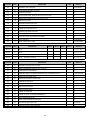
DATA 3
CATEGORY
DATA 4
EVENT
DESCRIPTION OF EVENT
"0"
"0-15"
"OPEN" on individual zones 1 thru 16
"1"
"0-15"
"OPEN" on individual zones 17 thru 32
"2"
"0-15"
"SHORT" on individual zones 1 thru 16
"3"
"0-15"
"SHORT" on individual zones 17 thru 32
"4"
"0-15"
"OPEN or SHORT" on individual zones 1 thru 16
"5"
"0-15"
"OPEN or SHORT" on individual zones 17 thru 32
"6"
"0-15"
"BYPASS" of individual zones 1 thru 16
"7"
"0-15"
"BYPASS" of individual zones 17 thru 32
"8"
"0-15"
"TROUBLE" on individual zones 1 thru 16
"9"
"0-15"
"TROUBLE" on individual zones 17 thru 32
"10"
"0-15"
"ALARM" on individual zones 1 thru 16
"11"
"0-15"
"ALARM" on individual zones 17 thru 32
"12"
"0"
Any "FIRE ALARM"
"1"
Any "PANIC ALARM"
"2"
Any "BURGLARY ALARM"
"3"
Any "TROUBLE CONDITION"
"4"
Any "BYPASS REPORT"
"5"
Any "EARLY TO OPEN"
"6"
Any "LATE TO CLOSE"
"7"
"AC FAILURE REPORT"
"8"
"DURESS"
"9"
"AUXILIARY 1"
"10"
"AUXILIARY 2"
"11"
"KEYPAD PANIC" (double keypress r and #)
"12"
"KEYPAD TAMPER"
"13"
"AUTO TEST"
"14"
"NOT ARMED"
"15"
"CANCEL"
19
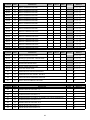
DATA 3
CATEGORY
DATA 4
EVENT
"13"
"0"
Activation of "PRIORITY (FIRE) SIREN"
"1"
Activation of "BURGLARY SIREN"
"2"
"ANY SIREN"
"3"
"ARMED WITH BYPASSED ZONE(S)"
"4"
"ALARM MEMORY"
"5"
"LOW BATTERY"
"6"
"ENTRY DELAY TIME"
"7"
"EXIT DELAY TIME"
“8"
“ENTRY AND EXIT DELAY TIME”
"9"
“INSTANT (PARTIAL) LED” illumination.
"10"
"ARMED LED" illumination.
"11"
"READY LED" illumination.
"12"
"AC LED" illumination.
"13"
"KEYPAD PULSING SOUNDER OR CHIME" activation.
"14"
"FIRE LED" illumination.
"15"
"FIRE TROUBLE LED" illumination.
"0"
"ANY VALID CODE ENTRY"
"14"
"1-15"
"15"
DESCRIPTION OF EVENT
"VALID CODE ENTRIES 1 THRU 15"
"0"
"DOUBLE KEYPRESS [1] & [3]”
"1"
"DOUBLE KEYPRESS [4] & [6]”
"2"
"DOUBLE KEYPRESS [7] & [9]”
"3"
"DOUBLE KEYPRESS [r] & [#]”
"4"
"RESETTABLE AUXILIARY/SMOKE DETECTOR POWER”
"5"
"DYNAMIC BATTERY TEST"
"6"
"LINE SEIZURE"
"7"
"OPEN ON ANY ZONE"
"8"
"SHORT ON ANY ZONE"
"9"
"OPEN OR SHORT ON ANY ZONE"
"10"
"GROUND START"
"11"
"TIME OF OPENING"
"12"
"DOWNLOAD COMPLETE"
"13"
"FAILED TO COMMUNICATE"
"14"
"PHONE LINE TROUBLE"
"15"
"LISTEN-IN TIME"
20
EXAMPLES
1)
To trip self contained siren when the Fire Siren activates:
To have Auxiliary 3 activate for the same time as the Fire Siren on the panel, program the following:
Location 232-235 [0]-[0]-[13]-[0]
2)
To trip self contained siren when the Burglary Siren activates:
To have Auxiliary 4 activate for the same time as Burglary Siren, program the following:
Location 236-239 [0]-[0]-[13]-[1]
3)
To activate external sounder when keypad chimes:
To have Auxiliary 3 follow the “chime” on the keypad, program the following:
Location 232-235 [0]-[0]-[13]-[13]
Note: You must move relay jumpers to set a voltage output (see page 4).
Location 240: Inverting Auxiliary Outputs And Setting Onboard Form C And Form A Relay Operation
(Form C Relay Tied To Pin #3 And Form A Relay Tied To Pin #4)
The auxiliary outputs of the 9000E are normally POSITIVE (+) going NEGATIVE (-). They can be changed to a
normally NEGATIVE (-)going POSITIVE (+) by programming the appropriate number in this location. Auxiliary output
1 has a value of "1", Auxiliary output 2 has a value of "2", Auxiliary output 3 has a value of "4", and Auxiliary output
4 has a value of "8". The values for the outputs that you wish to change to NEGATIVE going POSITIVE must be
added together and the total programmed in this location. For example, if you wished to make outputs 2 (=2) and
3 (=4) NEGATIVE going POSITIVE, you would program "6" (2+4=6) in this location. The output for pin 3 is
automatically tied to the onboard Form C Relay (Terminal locations 34,35, & 36), and pin 4 is tied to the Form A relay
(Terminal locations 38 & 39). You should take this into consideration when planning auxiliary output operation. If
you need a relay output on pins 1 or 2 you must add a relay that can be tripped with the voltage and current available
at these pins. Making outputs 3 and 4 normally negative going positive will have the effect of making the relay
attached to that pin normally pulled in, and drop out when the output is activated. NOTE: THE PINS ARE CURRENT
LIMITED TO 250 MICRO AMPS POSITIVE AND 20 mA NEGATIVE.
Location 241: Changing Timing Increments From Seconds To Minutes For Auxiliary Outputs
The number programmed into this location will determine if the 4 auxiliary pins described in the above locations will
create 2 to 28 second, or 1 to 14 minute voltage trigger outputs. If this location contains a "0" (factory default ="0"),
the output duration time is computed in seconds. By adding the value that corresponds to each pin number in the
table below, and programming the sum in this location, the "second" increments will convert to "minute" increments
for the pin(s) selected:
Example 1 - If you need the duration time to change from seconds to
minutes for the trigger output on Pin 1, you would
VALUE
PIN NUMBERS
program a "1" in this location.
1
Pin #1
Example 2 - If you need the duration time to change from seconds to
minutes for the trigger output on Pin 1 and Pin 3, you
2
Pin #2
would program a "5" (1 + 4 ="5") in this location.
4
Pin #3
Example 3 - If you need the duration time to change from seconds to
minutes for the trigger output on Pin 2 and Pin 4, you
8
Pin #4
would program a "10" (2 + 8 ="10") in this location.
21
Location 242: Answering Machine Defeat
Location 242 contains the answering machine defeat enable. To defeat an answering machine, two telephone calls
must be made to the premises. On the first call, let the phone ring the same number of times (or less) as the number
programmed in location 242 (maximum 3). The control panel will detect these rings and start a 45 second timer. If
a call comes in during that 45 second time frame, the control panel will answer on the first ring. To disable this
feature, program a "0" in this location.
Location 243: Number Of Rings To Answer Download Call
Location 243 contains the number of rings the 9000E must detect before answering the telephone when initiating
a download. If a number from "1" to "15" is programmed in this location, the control will answer after the number of
rings entered times 2 has been detected. If a "0" is programmed in this location, the 9000E will not answer the
download call. (SEE LOCATION 242: ANSWERING MACHINE DEFEAT)
Location 244: Assigning The Chime Enable Code
Program the one digit number that the end user will use to enable the Chime mode. This number can be any
number 1 to 9. Factory default is "1" and this feature is enabled. If you do not wish to enable the Chime feature at
this installation, program a "15" in this location. NOTE: This number should not be the same as the Quick Arm
code!
Location 245: Assigning The Entry-Guard Enable Code
Program the one digit number that the end user will use to activate the Entry-Guard mode. This number can be
any number 1 to 9. Factory default is "0" and this feature is disabled. NOTE! This code should not match the
Quick-Arm digit, or the Chime enable digit. Location 220 must contain a "0" for Entry-Guard to work.
PROGRAMMING FOR PARTITIONS
Locations 247 through 249 are used to program the number of zones in partitions 1, 2, and 3, with the remaining
zones automatically assigned to the next numerical partition, which would be 4 if all three locations are programmed.
If only the first location 247 has a number programmed in it, all remaining zones will automatically go to partition 2.
You can program any number of zones per partition up to a maximum of 15. All zones must be in numerical
sequence. For example, if you choose to have five zones in partition 1 and 11 zones in partition 2, you would
program a 5 in location 247 and zones 1-5 would be assigned to partition 1, while zones 6 through 16 would be
assigned to partition 2. You cannot assign zones out of sequence such as placing zones 1-3-5-7-9 in partition 1 and
2-4-6-8 in partition two. Factory default is no partitions enabled and all zones are assigned to partition 1 without
restriction. Note: When partitions are assigned in these locations, you may need to program locations 64-79, 124131, 132, 213, 217, 224, 228, 232, 236, 246, and 572-586 which are sensitive to partitioning.
Multiple Partition Access Option
For access to other partitions from a 9001 keypad, enter [C]-[9]-[9] followed by user code #28, followed by the
partition number that you wish to command. At this point, the keypad will act as though it is in the partition that you
have selected, and you can make commands as needed. While in this mode, to move to any other partition, you
need only to enter [C]-[9]-[9] and follow by the partition number. Anytime you are using this feature to gain access
to other partitions, the keypad you are using will return to its designated partition (the one selected on the dip
switches on the rear of the keypad) 20 seconds after the last keypress is entered. (When using a 9060E keypad,
refer to the 9060E User’s Manual.)
22
Location 246: Common Area Enable
If a "1" is programmed in location 246, Partition 1 will become a Common Area for all selected partitions. When
enabled, Partition 1 will automatically disarm when any other partition is disarmed, and will automatically arm when
all partitions have been armed (cannot be armed or disarmed independently). Care should be taken to allow
sufficient entry delay time for Partition 1 to allow the user to reach his designated partition keypad and enter a code.
Exit delay time is the delay for the last partition to arm. Factory default is "0" and this feature is disabled.
Location 247: Number Of Zones In Partition 1
Factory default is "0", and the control is not partitioned. Thus, all 16 (32 if expander is utilized) are assigned to the
one group. NOTE: When no partitions are enabled, all features or characteristics associated with partitions are
contained within one group.
Location 248: Number Of Zones In Partition 2
Factory default is "0", and Partition 3 is not enabled.
Location 249: Number Of Zones In Partition 3
Factory default is "0", and Partition 4 is not enabled.
Location 250: Power Up Condition
If a "1" is programmed in location 250 , the Ranger 9000E will power-up disarmed if there is a total power shutdown
and battery failure. If a "2" is programmed in this location, it will power-up armed. If this location contains a "0", the
Ranger 9000E will maintain the condition it was in at power-down. A watchdog circuit reset will cause the Ranger
9000E to reset to the selected condition. Factory default is "0" and the control will maintain the condition it was in
at power-down.
Location 251: Power Up Delay
The number programmed in location 251 represents the number of 10 second increments the Ranger 9000E will
delay before accepting open or short inputs from any zone. Factory default is "0" and this feature is disabled. If a
6 is selected, the delay will be 60 seconds. This delay period would also be initiated after a watchdog circuit reset
condition or when exiting from the program mode.
23
Location 252: Telephone Line Fault Monitor
Location 252 is used to program the telephone line monitor. Select a number from the table below which
corresponds to the activation required for your installation. Factory default is "0" and this feature is not enabled.
NOTE: When using a phone line monitor, it is suggested that a delay be programmed into location 253 to delay
alarm activation upon phone line fault. This could eliminate the possibility of a false alarm being created due to
phone line maintenance performed by the telephone company, which many times is performed during late night or
early morning hours.
VALUE
DESCRIPTION
"0"
DISABLED
"1"
ENABLED - SILENT MODE
"3"
ENABLED - ACTIVATE SIREN ONLY
"5"
ENABLED - ACTIVATE KEYPAD SOUNDER ONLY
"7"
ENABLED - ACTIVATE SIREN & KEYPAD SOUNDER
“9"
ENABLED - SILENT MODE (ARMED ONLY)
“11"
ENABLED - ACTIVE SIREN ONLY (ARMED ONLY)
“13"
ENABLED - ACTIVATE KEYPAD SOUNDER ONLY (ARMED ONLY)
“15"
ENABLED - ACTIVATE SIREN & KEYPAD SOUNDER (ARMED ONLY)
Location 253: Delay of Alarm Activation For Telephone Line Fault
The number programmed in this location determines the amount of time the Ranger 9000E will delay the alarm
activation selected in location 252. This delay is programmable in 10 second increments from 10 to 150 seconds.
Possible delay values are "1" ("1" x 10 seconds = 10 second delay) through "15" ( "15" x 10 seconds = 150 second
delay). Factory default is "0", no delay.
Location 254: Dynamic Battery Test Time
The number programmed in location 254 determines when the control will perform a dynamic battery test. This time
is programmable in two hour increments from 12:00 AM to 10:00 PM. Possible values for this location are "0" thru
"11". Factory default is "3" (3 x 2 = 6) meaning the dynamic battery test will occur at 6:00 AM. Programming a "0"
(0 x 2 = 0) in this location would set the test time for 00:00 (midnight). Programming a "11" (11 x 2 = 22) in this
location would set the test time for 22:00 (10:00 PM).
Location 255: Dynamic Battery Test Duration
The number programmed in location 255 will determine the number of minutes the Ranger 9000E will go into the
dynamic battery test mode during each 24 hour period. This test causes the control to function with the system
battery, thus verifying that the battery is capable of performing as designed during an actual power failure. Factory
default is "0" and this feature is not enabled.
24
SELECTING COMMUNICATOR CODES
All zones and other reported features are programmed with up to four (4) programming locations. The first three
(3) are used for a 1, 2, or 3, digit communicator code, according to the restraints of the selected communicator
format. The fourth (4th) and last location is used to select if the code is to be sent to phone #1, phone #2, the
internal log, activate listen-in, any combination of these selections, or all four options. Factory defaults to a three
digit event (alarm) code. NOTE: The first digit will be ignored when using a 3 + 1 Extended, or 4 + 2 format. The
first and second digit will be ignored when using a 3 + 1 or 4 + 1 format.
Locations 256-258: Programming The Communicator Code For Zone 1
Locations 256-258 contain the communicator codes to be reported each time zone 1 creates an alarm. Location 256
contains the first digit, location 257 contains the second digit, and location 258 contains the third digit. Always use
the correct number of digits that the selected format allows, and program in the order you wish the receiver to print
the report.
Location 259: Phone #1, 2, Internal Log, Listen-In, Or Any Combination For Zone 1
The number in this location will determine where the communicator report for zone 1 will be sent. This number is
derived by adding a "1" for phone #1, a "2" for phone #2, and a "4" for the internal log, and an "8" for activation of
Listen-In. If you want this code to be reported to both phone numbers, you must program a "3" (1 + 2 ="3") in this
location. If you want this code to be reported to both phone numbers and the internal log you must program a 7 (1
+ 2 + 4 ="7") in this location. Factory default is "13", which causes zone 1 to report to phone #1, the internal log, and
activate Listen-in (if used).
Locations 260-319: Programming The Communicator Code , & Selecting Phone #1, 2, Internal Log, Listen-in,
Or Any Combination For Zones 2 Thru 16 (See Instructions Above)
Locations 320-322: Communicator Code For Duress Code
The Ranger 9000E has the ability to report a Duress Code when the system is armed or disarmed with user code
number 15 (programmed in locations 056-059) and a duress communicator code is programmed in these locations.
If all locations are "0", the duress capability is disabled and user code 15 will act as a standard user code.
Location 323: Phone #1, 2, Internal Log, Listen-In, Or Any Combination For Reporting Duress.
IMPORTANT! Do Not Program A "4", Internal Log Only, In This Location! (See Location 259)
Locations 324-326: Communicator Code For Keypad Auxiliary 1 (Double Keypress [1] & [3])
The Ranger 9000E has the ability to report an Auxiliary 1 code and activate the Priority (FIRE) siren each time the
[1] and [3] keys are pressed simultaneously on the keypad. The desired 1 to 3 digit reporting code must be
programmed in these location(s). If all locations are "0", the Auxiliary 1 double keypress is disabled. If activated, the
siren can be silenced by entering any arm/disarm code.
Location 327: Phone #1, 2, Internal Log, Listen-In, Or Any Combination For Reporting Keypad Auxiliary 1
(Double Keypress [1] & [3]) (See Location 259)
Locations 328-330: Communicator Code For Keypad Auxiliary 2 (Double Keypress [4] & [6])
The Ranger 9000E will report an Auxiliary 2 code and activate the pulsing buzzer each time the [4] and [6] keys are
pressed simultaneously on the keypad. The desired 1 to 3 digit Auxiliary 2 code must be programmed in these
locations. If all locations are "0", the Auxiliary 2 double keypress is disabled. If activated, the keypad sounder can
be silenced by entering any Arm/Disarm code.
25
Location 331: Phone #1, 2, Internal Log, Listen-In, Or Any Combination For Reporting Keypad Auxiliary 2
(Double Keypress [4] & [6]) (See Location 259)
Locations 332-334: Communicator Code For Keypad Panic (Double Keypress [r] & [#])
The Ranger 9000E will report a Keypad Panic code and activate the Burglary siren each time the [r] and [#] keys
are pressed simultaneously on the keypad. The desired 1 to 3 digit Keypad Panic code is programmed in these
locations. If all locations are "0", the Keypad Panic double keypress is disabled. If activated, the siren can be
silenced by entering any Arm/Disarm code.
Location 335: Phone #1, 2, Internal Log, Listen-In, Or Any Combination For Reporting Keypad Panic (Double
Keypress [r] & [#]) See Location 259)
Locations 336-338: Communicator Code For Keypad Tamper Feature
The optional Keypad Tamper feature that, when enabled, will lock out the keypads for 1 minute if 30 random
keypresses are made without producing a valid code. The desired 1 to 3 digit Keypad Tamper code must be
programmed in these locations to enable this feature. If all locations are "0", the Keypad Tamper feature will not
be enabled or reported.
Location 339: Phone #1, 2, Internal Log, Listen-In, Or Any Combination For Reporting Keypad Tamper
(See Location 259)
Locations 340-342: Communicator Code For Autotest Reports
The Ranger 9000E has the ability to send Autotest reports at intervals from 1 to 99 days. The desired 1 to 3 digit
code must be entered in these location(s) to enable the Autotest feature. If all locations are "0", Autotest is
disabled. (NOTE: WHEN USING AUTOTEST, LOCATIONS 616-621 and 624-635 MUST BE PROGRAMMED.)
Location 343: Phone #1, 2, Internal Log, Listen-In, Or Any Combination For Autotest Reports (See Loc. 259)
Location 344: Phone Selector For Bypass Reports (See Location 259)
If this location is "0", bypass reports will follow the individual zone phone selections. If this location contains
something other than "0", it will be used for all bypass reports. If bypass reports are to go to the log without reporting,
program a "4" in this location.
Location 345: Phone Selector For Trouble Reports (See Location 259)
If this location is "0", trouble reports will follow the individual zone phone selections. If this location contains
something other than "0", it will be used for all trouble reports. If trouble reports are to go to the log without reporting,
program a "4" in this location.
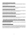
Location 346: Partition Open/Close Report Selector
The number programmed in this location will select
the partition(s) that will send open/close reports.
Refer to the table below, and add the values of the
partitions for open/close reports, and program the
appropriate data in this location. Factory default is
"0", enabling open/close reports for all partitions.
Example: For open/close reports from partitions
#1 and #3, program a "5" (1 + 4 = "5") in this
location.
VALUE
26
PARTITION NUMBER(S)
1
PARTITION #1
2
PARTITION #2
4
PARTITION #3
8
PARTITION #4
Location 347: Special Keypad Command Functions
When the system is armed and this location is programmed with something other than a "0", pressing the first digit
of the Master code followed immediately by the [r] key can create one or more of the changes described below.
Select the desired features from the table below, add their values, and program the sum in location 347. Factory
default is “1".
VALUE
DESCRIPTION
1
Remove Interior Follower Bypasses.
2
Remove Interior Delay Bypasses.
4
Remove Group Bypasses.
8
Restart The Exit Delay.
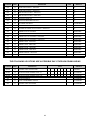
REPORTING USER NUMBERS FOR VARIOUS RECEIVER FORMATS
Due to the limitations and variations of certain formats, reporting of up to 30 unique user codes requires variable
programming for these formats, which are described below.
CONTACT ID OR SIA FORMATS When using these formats, program a "1" in location 348 to enable opening
reports. Program a"1" in location 350 to enable closing reports. Program a "1" in location 354 to enable cancel
reports. The correct event code and user number (1 thru 30) will be reported.
FBI SUPERFAST FORMAT When using this format, program the desired opening code in location 348, the desired
closing code in location 350, and the desired cancel code in location 354. The correct user number will be reported.
4 + 2, AND ALL EXTENDED FORMATS When using these formats, program the desired opening code for users
1 thru 15 in location 348. Program the desired closing code for users 1 thru 15 in location 350. Program the desired
cancel code for users 1 thru 15 in location 354. The user number for users 1 thru 15 will automatically be reported
as 1 thru F. Program the desired opening code for users 16 thru 30 in location 352. Program the desired closing code
for users 16 thru 30 in location 353. Program the desired cancel code for users 16 thru 30 in location 354. The user
number for users 16 thru 30 will automatically be reported as 1 thru F.
NON-EXTENDED FORMATS When using these formats, program the opening code in location 348, the desired
closing code in location 350, and the desired cancel code in location 354. User numbers will not be transmitted with
non-extended formats.
Location 348: Communicator Code To Report Openings For Users 1-15
The Ranger 9000E has the ability to report an opening code each time the control is disarmed. The desired opening
code is programmed in this location. If this location contains "0", openings will not be reported. When using 4+2
format, the number programmed in this location is sent first. The second digit is automatically the user number.
When using the Quick-Arm digit, the user number is 29. When using a keyswitch, the user number is 30.
Location 349: Select Phone #1, 2, Internal Log, Or Any Combination To Report Openings For Users 1-15
(See Location 259)
27
Locations 350: Communicator Code To Report Closings For Users 1-15
The Ranger 9000E has the ability to report a closing code each time the control is armed. The desired closing code
is programmed in this location. If this location contains a "0", closings will not be reported. The number programmed
in this location is sent first. The second digit is automatically the user number. When using Auto Arm the user
number is 28. When using the Quick Arm digit, the user number is 29. When using a keyswitch, the user number
is 30. The closing report will not be initiated until the end of the exit delay.
Location 351: Select Phone #1, 2, Internal Log, Or Any Combination To Report Closings For Users 1-15
(See Location 259)
Location 352: Communicator Code To Report Closings For Users 16-30
This location will be programmed only when using a 4 + 2, or extended format.
Location 353: Communicator Code To Report Openings For Users 16-30
This location will be programmed only when using a 4 + 2, or extended format.
Location 354: Communicator Code To Report Cancel (Exception Opening) For Users 1-15
Location 354 contains the communicator code that will be sent to identify users numbered 1-15 for Cancel. The
Cancel code programmed in this location will be sent if an arm/disarm code is entered after a trip on any zone has
been reported (excluding Fire zones). After a cancel has been reported, no loop restorals will be transmitted on
non-24 Hour zones. The number programmed in this location is sent first. The second digit is automatically the user
number. If this location contains a "0", Cancel is disabled. (When using a key switch, the user # is 30.)
Location 355: Communicator Code To Report Cancel (Exception Opening) For Users 16-30
This location will be programmed only when using a 4 + 2, or extended format.
Locations 356-358: Communicator Code For Reporting AC Power Loss
The Ranger 9000E has the ability to report an AC Power Loss code after the AC power has been off for a selected
number of minutes from 0 to 15 (see location 623). The desired 1 to 3 digit AC failure code is programmed in these
locations. If all locations are "0", AC Power Loss will not be reported.
Location 359: Select Phone #1, 2, Internal Log, Or Combination To Report AC Power Loss (See Location 259)
Location 360-362: Communicator Code For Reporting Low Battery
The Ranger 9000E has the ability to report a Low Battery code when AC power has been lost and the battery has
discharged down to 10.3 volts. The desired 1 to 3 digit Low Battery code is programmed in these locations. If all
locations are "0", Low Battery will not be reported.
Location 363: Select Phone #1, 2, Internal Log, Or Combination For Reporting Low Battery (See Location 259)
The following locations allow for transmitting variable Restore report codes in zone blocks of 8. If a code
is selected for zones 1-8 in location 364 it will apply to all zones unless individual codes are selected in
locations 365-367. If location 364 is "0" no zone restorals will be reported. If locations 365-367 are "0", the
code in location 364 will be sent.
Location 364: Restore Code For Zones 1 Thru 8
Location 365: Restore Code For Zones 9 Thru 16
Location 366: Restore Code For Zones 17 Thru 24 (When Using Expansion System)
Location 367: Restore Code For Zones 25 Thru 32 (When Using Expansion System)
28
The following locations allow for the transmitting of variable bypass report codes in zone blocks of eight (8).
If a code is selected for zones 1-8 in location 368, it will apply to all zones unless individual codes are
selected for locations 369-371. If location 368 contains a "0", no bypass reports will be sent. If enabled,
bypass reports will be made at the end of the exit delay for non-24 hour zones. 24 hour zones will report
a bypass immediately. When a bypass is removed, a "Restore" will be reported if "Restore" is enabled in
location 364.
Location 368: Zone Bypass Code For Zones 1 Thru 8
Location 369: Zone Bypass Code For Zones 9 Thru 16
Location 370: Zone Bypass Code For Zones 17 Thru 24 (When Using Expansion System)
Location 371: Zone Bypass Code For Zones 25 Thru 32 (When Using Expansion System)
The following locations allow for the transmitting of variable trouble report codes in zone blocks of eight (8).
If a code is selected or zones 1-8 in location 372 it will apply to all zones unless individual codes are selected
for locations 373-375. If location 372 is "0", no trouble reports will be sent.
Location 372: Zone Trouble Code For Zones 1 Thru 8
Location 373: Zone Trouble Code For Zones 9 Thru 16
Location 374: Zone Trouble Code For Zones 17 Thru 24 (When Using Expansion System)
Location 375: Zone Trouble Code For Zones 25 Thru 32 (When Using Expansion System)
Location 376: Programming For AC Power And Low Battery Restore Code
If this location contains a "0", no AC Power or Low Battery restorals will be sent. Anything other than a “0"
programmed in this location will cause the AC and Low Battery restore codes to be sent to the central station. AC
Restore will be sent after the delay time programmed in location 623.
Location 377: Programming The Number Of Expansion Devices On The Buss Loop
This location is used to program the number of expansion devices added to the buss loop. DO NOT INCLUDE
KEYPADS IN THIS COUNT! The maximum number of expansion devices that can be added to the Ranger 9000
is seven, therefore the largest number that can be programmed in this location is "7". Factory default for this
location is "0".
Location 378: Communicator Code For Expansion Trouble
Location 378 contains the extended communicator code digit for Expander Trouble. The second digit, or zone
ID, of this report will be the number of the expansion device that is in trouble. The Expander Trouble Restore
code is programmed in location 511.
Location 379: Phone Number To Report Expansion Trouble Code
Location 379 is used to select the phone number to report Expander Trouble. Program a "1" in this location to
report to phone #1 only. Program a "2" to report to phone #2 only. Program a "3" to report to both phone numbers.
If an "8" is programmed in this location, Expander Trouble will cause zone 32 to "open", and cause Expander
Trouble take on the reporting and alarm characteristics of zone 32.
29
Locations 380-395: Programming The Zone Types For Zones 17-32
Locations 380 through 395 contain a number identifying the Zone Types of zones 17 through 32. Location 380
corresponds to zone 17 and location 395 corresponds to zone 32. Each zone 17-32 has been factory defaulted
to a "6", "Instant" zone type. To program zone types other than the default values, program a number from "1"
to "9" based on the "Available Zone Types" table below.
DATA
AVAILABLE ZONE TYPES
"1"
DAY ZONE - When armed, a trip produces an instant alarm. When disarmed, a trip activates the
keypad sounder.
"2"
24 HOUR - A trip on a 24 Hour zone produces an instant alarm when armed or disarmed.
"3"
ENTRY/EXIT - A trip will start entry delay. The lack of a trip during exit delay will enable the
Automatic Bypass or Instant mode if so programmed.
"4"
INTERIOR DELAY - A trip on Interior Delay zone will initiate an entry delay. It will be ignored during
exit delay and when disarmed .
"5"
INTERIOR FOLLOWER - Interior zone that follows the delay zones. It is instant during non-delay
times. It can be bypassed before arming, or by allowing it to automatically be bypassed in the
Automatic Bypass/Instant mode if so programmed.
"6"
INSTANT - Produces an instant alarm if tripped when armed. Ignored when disarmed.
"7"
SECONDARY DELAY - Like an Entry/Exit zone but has its own independent delay time.
"8"
FIRE (PRIORITY WHEN AHJ HAS NOT APPROVED) - A short on a FIRE zone (non-bypassable)
will communicate to the central station when the Ranger 9000E is armed or disarmed. An open will
create a Trouble condition. Keypad LED will be steady for FIRE, and flashing for Trouble.
"9"
KEYSWITCH - A zone attached to a momentary keyswitch will cause the Ranger 9000E to arm or
disarm when the zone is shorted. NOTE: Program the corresponding "Special Characteristics For
Zones 17-32"(locations 396-411) as a "0".
Locations 396-411: Assigning Special Characteristics For Zones 17-32
Locations 396 through 411 are used to assign Special Characteristics for zones 17 through 32. Location 396
corresponds to zone 17 and location 411 corresponds to zone 32. Each zone can have any or all of the following
characteristics regardless of the zone type selected in locations 380-395, excluding Fire zones which cannot have
bypass capability enabled. Factory default is "12" for each of these locations, meaning that Zone Bypass
Capability & Entry-Guard are enabled, and the other characteristics are not enabled. To include other
characteristics, add the values, and program the sum in the appropriate location. See the table below for zone
characteristics and their corresponding values.
VALUE
CHARACTERISTIC
1
Fast Loop Response
(200mS)
2
Group Bypass Zone
4
Entry-Guard Zone
8
Zone Bypass Capability
Example 1 - To add Group Bypass Zone (Value=2) to Zone
Bypass Capability (Value=8) for zone 20 (location 399), add
the value of the two characteristics (2 + 8 ="10"), and program
the sum of "10" in location 399.
Example 2 - To enable ALL characteristics for zone 20, add the
value of all characteristics (1 + 2 + 4 + 8 = "15"), and program
the sum of "15" in location 399 (zone 10 characteristics
location).
Example 3 - To disable all characteristics and create a Non
Bypassable Zone, program a "0" in the appropriate location.
30
Locations 412-427: Assigning Audible Characteristics For Zones 17-32
Locations 412-427 are used to assign the Audible Characteristics for zones 17 through 32. Location 412
corresponds to zone 17, and location 427 corresponds to zone 32. To determine the appropriate data for these
locations, refer to the chart below and add the sum of the corresponding values to arrive at the correct data for
these locations. Zones 17-32 have a factory default setting of "13" (1+ 4 + 8 = "13"). This means that zones 17-32
will create a yelp siren output and a keypad sounder output when an alarm is created. To select the audible
characteristics for any zone, add the values of the audible characteristics from the table below, and program the
sum in the appropriate locations 412-427. NOTE: If a Fire zone type is selected in locations 380-395, standard
fire zone characteristics will override any selection made for a zone in this section. If you wish for the zone to be
SILENT, program a "0" in the appropriate location.
VALUE
AUDIBLE CHARACTERISTICS
0
Silent
1
Yelp Siren Audible
2
Steady Siren Audible
4
Keypad Sounder Audible
8
Chime Enable
Locations 428-443: Special Communicator Reporting Characteristics For Zones 17-32
Locations 428-443 are used to assign communicator characteristics to individual zones 17 through 32. Location
428 is for zone 17 and location 443 is for zone 32. Each zone can have one, or any combination of these
characteristics. Factory default for all zones is "11" (1 + 2 + 8 ="11"). This means that each zone has RESTORE
REPORTING (Value=1), BYPASS REPORTING (Value=2), and REPORT CANCELING (Value=8) enabled. It
should be noted that these locations are used to enable individual zone report capability by zone. A reporting code
must be programmed in the appropriate location to enable overall reporting capability of Restore reports (location
364), Bypass reports (location 368), Trouble/24 Hour Tamper reports (location 372), and Cancel reports (location
354).
VALUE
REPORTING CHARACTERISTICS
1
Restore Reporting
2
Bypass Reporting
4
Trouble/24 Hour Tamper Reporting
8
Report Canceling
31
SELECTING COMMUNICATOR CODES FOR ZONES 17-32
All zones and other reported features are programmed with up to four (4) programming locations. The first three (3) are
used for a 1, 2, or 3, digit communicator code, according to the restraints of the selected communicator format. The
fourth (4th) and last location is used to select if the code is to be sent to phone #1, phone #2, the internal log, activate
listen-in, any combination of these selections, or all four options. The following example will assist you in this selection
process. Factory defaults to a three digit event (alarm) code. NOTE: The first digit will be ignored when using a 3 + 1
Extended, or 4 + 2 format. The first and second digit will be ignored when using a 3 + 1 or 4 + 1 format.
Locations 444-446: Programming The Communicator Code For Zone 17
Locations 444-446 contain the communicator codes to be reported each time zone 17 creates an alarm. Location
444 contains the first digit, location 445 contains the second digit, and location 446 contains the third digit. Always
use the correct number of digits that the selected format allows. Program in the order you wish the receiver to print
the report.
Location 447: Select Phone #1, 2, Internal Log, Or Any Combination For Zone 17
The number in this location will determine where the communicator report for zone 17 will be sent. This number is
derived by adding a “1" for phone #1, a “2" for phone #2, and a “4" for the internal log and an “8" for activation
of Listen-in. If you want this code to be reported to both phone numbers you must program a "3" (1+2) in this
location. If you want this code to be reported to both phone numbers and the internal log you must program a
"7" (1+2+4) in this location. Factory default is “13", which causes zone 17 to report to phone #1, the internal log,
and activate Listen-in, if used.
Location 448-507: Programming The Communicator Code and Selecting Phone Number 1, 2, Internal Log,
Listen-in, or Any Combination For Zones 18-32 (See Locations 444 - 447)
Location 508: Reserved
Location 509: Listen-In Time
Program the number of minutes desired for Listen-in at this location (maximum 7 minutes). Factory default is “0".
Location 510: Dial Attempts To Phone #2
This location contains the number of dial attempts to the second phone number for a dual or split report to the
second phone number. This is useful when the second number is a pager. Factory default is “0".
Location 511: Expander Trouble Restore Code
Location 511 contains the Expander Restoral Code. If this location is “0", restorers will not be reported.
Locations 512-571: Programming The Arm/Disarm Code For Users 16-30
Locations 512-571 contain the arm/disarm codes for user numbers 16 thru 30. EACH CODE MUST CONTAIN FOUR
(4) DIGITS. To disable a code, program a "15" as the first digit of the code. This code can be changed in the RUN
mode using the master code (see User’s Manual). The factory default for users 16 thru 30 is "15", disabled.
Locations 572-586: Users 16-30 Arm/Disarm Code Enable By Partition
PARTITIONED SYSTEMS
If partitions are utilized, codes may be assigned to a
specific partition by using locations 572-586. This is
done by enabling each individual code (code 16 is
location 572, code 30 is location 586) for each of the
four partitions that code should have access to.
Codes are selected by adding the value for each
partition together and placing that number in the
proper location.
VALUE
1
2
4
8
32
PARTITIONS
PARTITION 1
PARTITION 2
PARTITION 3
PARTITION 4
NON - PARTITIONED SYSTEMS
When partitioning is not being utilized, locations
572-586 can be used to control the arming and
disarming authority of the individual arm/disarm
codes. A code can be given limited authority by
programming a number from 1 to 15 in the
corresponding location for that code. Add the values
in the table below that correspond to the desired
arm/disarm characteristics, and program the sum in
the appropriate locations.
VALUE
CHARACTERISTIC
1
STANDARD ARM/DISARM CODE
2
ARM ONLY AFTER CLOSING TIME
4
ARM ONLY CODE
8
OPEN/CLOSE REPORTS FOR USER
Location 587: Early-To-Open, Late-To-Close And/Or Automatic Arming Features
To enable the early-to-open and late-to-close features program a "1" in this location. If you also wish to enable the
automatic arming feature, program a "2" in this location. To enable both features, program a “3" in this location. A
time must be entered into locations 600-603 and 604-607 to enable these features. The Automatic Arming feature
will arm the Ranger 9000E at the selected time. At that time, the keypad sounders will sound for 50 seconds, warning
anyone who remains in the protected building that the system is about to automatically arm. If a valid code is not
entered before the end of the 50 second warning time, the system will automatically arm. If a valid code is entered,
a late to close signal will be transmitted. NOTE: If open/close reports are used, Automatic Arming will report user
28.
Locations 588-590: Communicator Code For Late-To-Close Report
The Ranger 9000E has the ability to report a 1 to 3 digit late-to-close report when these location(s) are programmed
and a closing time has been programmed in locations 604-607. Factory default is "0" for all locations and this feature
is not enabled.
Location 591: Select Phone #1, 2, Internal Log, Or Combination For Late-To-Close Reports
447)
(See Location
Locations 592-594: Communicator Code For Early Opening Report
The Ranger 9000E has the ability to report a 1 to 3 digit early opening code when these location(s) are programmed
and a opening time has been programmed in locations 600-603. Factory default is "0" for all locations and this
feature is not enabled.
Location 595: Select Phone #1, 2, Internal Log, Or Combination For Reporting Early Opening (See Location 447)
Location 596-598: Communicator Code To Report Downloading Complete
Locations 596-598 contain the communicator report sent each time a download session has been completed. The
report will come in after a disconnect has been made from a downloading session. If these locations contain "0", this
report is disabled.
Location 599: Select Phone #1, 2, Internal Log, Or Any Combination To Report Downloading Complete
Locations 600-603: Opening Time
To enable the early-to-open report feature, a 4 digit 24 hour opening time must be entered in locations 600-603. For
example, to enter a opening time of 8:15 a.m.(08:15), program a "0" in location 600, a "8" in location 601, a "1" in
location 602, and a "5" in location 603. Factory default is a "0-6-0-0" which sets an opening time of 6:00 AM. NOTE:
A communicator code must be entered in location(s) 592-594 if this feature is selected.
33
Locations 604-607: Closing Time
To enable the late-to-close report, a 4-digit, 24 hour closing time must be entered in locations 604-607. For example,
to enter a closing time of 6:30 p.m.(1830), program a "1" in location 604, a "8" in location 605, a "3" in location 606,
and a "0" in location 607. Factory default is a "2-0-0-0" which sets a closing time of 8:00 PM. NOTE: A
communicator code must be entered in location(s) 588-590 if this feature is selected.
Location 608: Closed Saturday Enable
A "1" should be programmed in location 608 if the installation will be closed on Saturdays and early-to-open or late
to close features have been enabled. A "1" will cause the early-to-open report to be communicated in the event an
opening is made on Saturday. Factory default is "0", and openings are allowed on Saturday within the assigned
schedule without creating a report.
Location 609: Closed Sunday Enable
A "1" should be programmed in location 609 if the installation will be closed on Sundays and early-to-open or late
to close features have been enabled. A "1" will cause an early-to-open to be communicated in the event an opening
is made on Sunday. Factory default is "0", and openings are allowed on Sunday with the assigned schedule without
creating a report.
Locations 610-615: Format Overrides (See Appendix)
Location 616: Programming The Hour For Autotest - Tens Digit
Location 616 contains the tens digit of the hour that the autotest report is initiated. The time is entered in 24 hour
time. If the desired autotest time is 5:25 PM, the 24 hour time is 17:25, so this location should contain a "1", which
is the tens digit of the desired hour for autotest. If the desired autotest time is 9:36 AM, the 24 hour time is 09:36,
and this location should contain a "0".
Location 617: Programming The Hour For Autotest - Ones Digit
Location 617 contains the ones digit of the hour that the autotest report is desired. The time is entered in 24 hour
time. If the desired autotest time is 5:25 PM, the 24 hour time is 17:25, so this location should contain a "7", which
is the ones digit of the hour for autotest. If the desired autotest time is 9:36 AM, the 24 hour time is 09:36, and this
location should contain a "9".
Location 618: Programming The Minutes For Autotest - Tens Digit
Location 618 contains the tens digit, of the minutes after the hour that the autotest is desired. The time is entered
in 24 hour time. If the desired autotest time is 5:25 PM, the 24 hour time is 17:25, so this location should contain a
"2", which is the tens digit of the minutes for autotest time. If the desired autotest time is 9:36 AM, the 24 hour time
is 09:36, and this location should contain a "3".
Location 619: Programming The Minutes For Autotest - Ones Digit
Location 619 contains the ones digit, of the minutes after the hour that the autotest is desired. The time is entered
in 24 hour time. If the desired autotest time is 5:25 PM, the 24 hour time is 17:25, so this location should contain a
"5", which is the ones digit of the minutes for autotest time. If the desired autotest time is 9:36 AM, the 24 hour
time is 09:36, and this location should contain a "6".
34
Locations 620-621: Autotest Report Intervals
Locations 620 and 621 contain the number of days in the autotest report intervals. Location 620 is the tens (10's)
digit, and location 621 is the ones (1's) digit. The available interval is 1 to 99 days. If a 1 to 9 day interval is selected
the first location should remain a zero "0". If the selected interval is every 75 days, you would program a "7" in
location 620 and a "5" in location 621. Locations 340-342 must be programmed to enable autotest reporting.
Location 622: Automatic Download Callback Enable/Autotest Suppression
Programming a "1" in location 622 will cause the control panel to automatically call the download computer callback
number at every autotest interval. This feature will not activate unless a callback phone number has been
programmed, and a "2" is programmed in location 660. If a "2" is programmed in location 622, the autotest report
will be suppressed, if the communicator has sent any report since the last autotest. To enable both features,
program a “3" in this location. Factory default is “0".
Location 623: AC Power Loss Delay Feature
The number programmed in location 623 represents the number of 1 minute increments the AC Power Loss report
is delayed before a communication is initiated, from 1 to 15 minutes. Factory default is "5" programmed in this
location and AC Power Loss reports will be delayed 5 minutes. If a "0" is programmed in this location this feature
is not enabled. The AC Power Restore, if enabled in location 376, will also delay reporting until after the number
of minutes programmed in this location has elapsed.
Location 624-625: Programming The Number Of Elapsed Days Since Last Auto Test Report
Location 624 contains the tens digit of the number of days between autotest reports and location 625 contains the
ones digit. Example: If today is Thursday, and you want a weekly test on Sundays (a "0 - 7" in locations 620-621),
program a "0" in location 624, and a "4" in location 625 (four days have elapsed).
Location 626: Programming Current Day Of Week
A number from 1 to 7 should be programmed in this location to indicate the current day of the week. Program a “2"
in this location for a Monday. If the day is Friday, program a "6" in this location. Sunday ="1" and Saturday ="7".
Location 627: Programming The Current Month
Location 627 contains the current month. The month must be programmed using a number from "1" to "12".
Location 628: Programming The Current Day Of Month - Tens Digit
Location 628 should be programmed with first digit of the current day of the month. If the current date is December
25th, program a "2" in location 628.
Location 629: Programming The Current Day Of Month - Ones Digit
Location 629 should be programmed with the second digit of the current day of the month. If the current date is
December 25th, program a "5" in location 629.
Location 630: Programming The Current Year - Tens Digit
Location 630 contains the current year - tens digit. If the current year is 1996, this location should contain a 9, which
is the tens digit of the current year.
35
Location 631: Programming The Current Year - Ones Digit
Location 631 contains the current year - ones digit. If the current year is 1996, this location should contain a "6",
which is the ones digit of the current year. If the current year is 1997, this location should contain a "7", which is the
ones digit of the current year.
Location 632: Programming The Current Hour - Tens Digit
Location 632 contains the current hour - tens digit. The time is entered in 24 hour time. If the current time is 5:25 PM,
the 24 hour time is 17:25, so this location should contain a "1", which is the current hour - tens digit. If the current
time is 9:36 AM, the 24 hour time is 09:36, so this location should contain a "0".
Location 633: Programming The Current Hour - Ones Digit
Location 633 contains the current hour - ones digit. The time is entered in 24 hour time. If the current time is 5:25
PM, the 24 hour time is 17:25, so this location should contain a "7", which is the current hour - ones digit. If the
current time is 9:36 AM, the 24 hour time is 09:36, and this location should contain a "9".
Location 634: Programming The Current Minutes - Tens Digit
Location 634 contains the current minutes - tens digit. The time is entered in 24 hour time. If the current time is 5:25
PM, the 24 hour time is 17:25, so location 160 should contain a "2", which is the current minutes - tens digit. If the
current time is 9:36 AM, the 24 hour time is 09:36, and this location should contain a "3".
Location 635: Programming The Current Minutes - Ones Digit
Location 635 contains the current minutes - ones digit. The time is entered in 24 hour time. If the current time is 5:25
PM, the 24 hour time is 17:25, so this location should contain a "5", which is the current minutes - ones digit. If the
current time is 9:36 AM, the 24 hour time is 09:36, and this location should contain a "6".
THE FOLLOWING LOCATIONS ARE ACCESSIBLE ONLY THROUGH DOWNLOADING
Locations 636-643: Control Panel Access Code
Locations 636-643 contain the eight digit access code the 9000E must receive from the downloading software
before the panel will permit downloading to occur. The factory default code is listed in the instructions provided with
the CADDX download software package.
Locations 644-659: Call Back Telephone Number
If a telephone number is programmed into these locations, and "callback" is enabled in location 660, the control
panel will hang up for approximately 36 seconds (insuring that the calling party has disconnected), and then call
back. If tone dialing is desired, program an "F" in the location where tone dialing should begin. If the entire number
should be tone dialing, program an "F" in location 644. Four second delays can be obtained anywhere in the
sequence by programming a "D" in the appropriate delay location. WARNING: THE CALLBACK PHONE NUMBER
SHOULD ALWAYS BE REVIEWED FOR ACCURACY BEFORE DISCONNECTING.
36
Location 660: Call Back Optional Features
The number programmed in location 660 will set the callback options for the control panel. Any or all of the features
below can be obtained by programming the appropriate data in this location. The correct data can be obtained by
ADDING the values of the corresponding characteristics from the table below (possible values are 0 to 7).
VALUE
CHARACTERISTIC
1
Panel will automatically callback for download session.
2
Site initiated download call by entering [r]-[9]-[8]-[#] at keypad,
and/or automatic callback if a "1" is programmed in location 622.
4
Panel will automatically callback when the event log is full.
Example 1 - Programming a "5" (1 + 4 = 5) in this location will combine the characteristics for values 1 and 4.
Example 2 - Programming a "7" (1 + 2 + 4 = 7) in this location will combine all of the characteristics described.
Location 661: Local Programming Lockout
Location 661 is used to disable local programming lockout. If a "5" is programmed in this location, all local
programming is locked out. If an "A" is programmed in this location, all programming functions related to the digital
communicator will be locked out. Any other number in location 661 will allow all local programming.
Location 662: Control Panel Shutdown
Location 662 is used to shutdown the control panel. Programming an "A" in this location will completely shutdown
the control panel. The keypad will appear "dead" with only the "Trouble" LED illuminated, and the siren and
communicator will not operate. WARNING: EXTREME CARE SHOULD BE TAKEN NOT TO INADVERTENTLY
PROGRAM THIS LOCATION.
KEYPAD SETTINGS FOR PARTITIONED SYSTEMS
The keypads used with the Ranger 9000E control panel have a 4-position dip switch on the PC board that is easily
accessed from the back of the keypad. If partitioning is not being used, all switches must be in the “OFF” position.
If partitioning is being used, refer to the table below to set the keypads for use in the correct partition.
PARTITION NUMBER
SWITCH 1
SWITCH 2
PARTITION #1
OFF
OFF
PARTITION #2
ON
OFF
PARTITION #3
OFF
ON
PARTITION #4
ON
ON
The positions of dip switches 1 and 2 determine the partition to which the keypad belongs, as indicated in the table
above. For example, if the keypad is in Partition 3, Switch 1 should be “OFF”, and Switch 2 should be “ON”.
Switches 3 & 4 are reserved for future use, and should be in the “OFF” position at all times. All keypads are shipped
from the factory for Partition 1 usage (switches 1 & 2 “OFF”). NOTE: These keypads will not function properly if the
correct partition is not selected.
37
ARM/DISARM CODES 1 - 15
LOCATION
PAGE
DESCRIPTION
DATA 1
DATA 2
DATA 3
DATA 4
"DEFAULT"
000-003
8
USER #1 ARM/DISARM CODE
"1-2-3-4"
004-007
8
USER #2 ARM/DISARM CODE
"15" DISABLED
008-011
8
USER #3 ARM/DISARM CODE
"15" DISABLED
012-015
8
USER #4 ARM/DISARM CODE
"15" DISABLED
016-019
8
USER #5 ARM/DISARM CODE
"15" DISABLED
020-023
8
USER #6 ARM/DISARM CODE
"15" DISABLED
024-027
8
USER #7 ARM/DISARM CODE
"15" DISABLED
028-031
8
USER #8 ARM/DISARM CODE
"15" DISABLED
032-035
8
USER #9 ARM/DISARM CODE
"15" DISABLED
036-039
8
USER #10 ARM/DISARM CODE
"15" DISABLED
040-043
8
USER #11 ARM/DISARM CODE
"15" DISABLED
044-047
8
USER #12 ARM/DISARM CODE
"15" DISABLED
048-051
8
USER #13 ARM/DISARM CODE
"15" DISABLED
052-055
8
USER #14 ARM/DISARM CODE
"15" DISABLED
056-059
8
USER #15 ARM/DISARM CODE
"15" DISABLED
060-063
8
"GO TO PROGRAM" ACCESS CODE
"9-7-1-3"
ENABLING ARM/DISARM CODES 1-16 BY PARTITION (OPTIONAL)
LOCATION
PAGE
DESCRIPTION
64
8
PARTITION(S) FOR USER #1 ARM/DISARM CODE
"15" ALL
65
8
PARTITION(S) FOR USER #2 ARM/DISARM CODE
"15" ALL
66
8
PARTITION(S) FOR USER #3 ARM/DISARM CODE
67
8
PARTITION(S) FOR USER #4 ARM/DISARM CODE
VALUE
68
8
PARTITION(S) FOR USER #5 ARM/DISARM CODE
1
Partition # 1
"15" ALL
69
8
PARTITION(S) FOR USER #6 ARM/DISARM CODE
2
Partition # 2
"15" ALL
70
8
PARTITION(S) FOR USER #7 ARM/DISARM CODE
4
Partition # 3
"15" ALL
71
8
PARTITION(S) FOR USER #8 ARM/DISARM CODE
8
Partition # 4
"15" ALL
72
8
PARTITION(S) FOR USER #9 ARM/DISARM CODE
73
8
PARTITION(S) FOR USER #10 ARM/DISARM CODE
74
8
PARTITION(S) FOR USER #11 ARM/DISARM CODE
75
8
PARTITION(S) FOR USER #12 ARM/DISARM CODE
1
Standard Arm/Disarm code
"15" ALL
76
8
PARTITION(S) FOR USER #13 ARM/DISARM CODE
2
Arm Only after Closing Time
"15" ALL
77
8
PARTITION(S) FOR USER #14 ARM/DISARM CODE
4
Arm Only Code
"15" ALL
78
8
PARTITION(S) FOR USER #15 ARM/DISARM CODE
8
Open/Close Report for User
"15" ALL
79
8
PARTITION(S) FOR "GO TO PROGRAM" ACCESS CODE
38
DATA
PARTITIONED SYSTEMS
CHARACTERISTIC
"DEFAULT"
"15" ALL
"15" ALL
"15" ALL
NON PARTITIONED SYSTEMS
VALUE
CHARACTERISTIC
"15" ALL
"15" ALL
"15" ALL
PHONE #1
LOCATION
PAGE
DESCRIPTION
PHONE NUMBER
"DEFAULT"
80-87
9
PHONE #1, DIGITS 1 - 8
"14" DISABLED
88-95
9
PHONE #1, DIGITS 9 - 16
"14" DISABLED
PRIMARY ACCOUNT NUMBER
LOCATION
PAGE
96-100
9
DESCRIPTION
ACCOUNT CODE
PRIMARY ACCOUNT NUMBER
"DEFAULT"
"0" DISABLED
PRIMARY FORMAT
LOCATION
PAGE
101
9
DESCRIPTION
FORMAT
PRIMARY FORMAT
"DEFAULT"
"0" DISABLED
PHONE #2
LOCATION
PAGE
DESCRIPTION
PHONE NUMBER
"DEFAULT"
102-109
9
PHONE #2, DIGITS 1 - 8
"14" DISABLED
110-117
9
PHONE #2, DIGITS 9 - 16
"14" DISABLED
SECONDARY ACCOUNT NUMBER
LOCATION
PAGE
118-122
9
DESCRIPTION
ACCOUNT CODE
SECONDARY ACCOUNT NUMBER
"DEFAULT"
"0" DISABLED
SECONDARY FORMAT
LOCATION
PAGE
123
9
DESCRIPTION
FORMAT
SECONDARY FORMAT
"DEFAULT"
"0" DISABLED
PARTITION #3 & #4 ACCOUNT NUMBER (OPTIONAL)
LOCATION
PAGE
DESCRIPTION
ACCOUNT CODE
"DEFAULT"
124-127
10
PARTITION #3 ACCOUNT CODE
"0" DISABLED
128-131
10
PARTITION #4 ACCOUNT CODE
"0" DISABLED
FORMAT SELECTIONS
DATA
FORMAT
DESCRIPTION
“0"
LOCAL ONLY
COMMUNICATOR IS DISABLED
“1"
ADEMCO CONTACT ID
DTMF FORMAT
“2"
ADEMCO 4/2 EXPRESS
DTMF FORMAT
“3"
FBI SUPERFAST
DTMF FORMAT 2300Hz
“4"
PAGER
DTMF FORMAT
“5"
RADIONICS EXTENDED SLOW
1800Hz TRANSMITTAL 2300Hz HANDSHAKE 20 PPS HEX EXTENDED DOUBLE ROUND
“6"
CADDX MODEM
PROPRIETARY
“7"
RADIONICS EXTENDED FAST
1800Hz TRANSMITTAL 2300Hz HANDSHAKE 40 PPS HEX EXTENDED DOUBLE ROUND
“8"
RADIONICS EXTENDED FAST
1800Hz TRANSMITTAL 1400Hz HANDSHAKE 40 PPS HEX EXTENDED DOUBLE ROUND
“9"
RADIONICS EXTENDED FAST W/PARITY
1800Hz TRANSMITTAL 2300Hz HANDSHAKE 40 PPS HEX EXTENDED
“10"
UNIVERSAL 4 + 2
1800Hz TRANSMITTAL 2300Hz HANDSHAKE DOUBLE ROUND 20PPS
“11"
ADEMCO / SILENT KNIGHT SLOW
1900Hz TRANSMITTAL 1400Hz HANDSHAKE 10 PPS DOUBLE ROUND PARITY
“12"
SILENT KNIGHT 4 + 2 FAST
1900Hz TRANSMITTAL 1400Hz HANDSHAKE 20 PPS DOUBLE ROUND PARITY ADD HEX
“13"
SESCOA/FRANKLIN FAST
1800Hz TRANSMITTAL 2300Hz HANDSHAKE 20 PPS DOUBLE ROUND PARITY
“14"
SIA
FSK FORMAT
“15"
OVER-RIDE ENABLE
SEE LOCATIONS 610-615
(SEE APPENDIX 2)
(SEE APPENDIX 1)
39
LOCATION
PAGE
DESCRIPTION
DATA
132
11
PHONE SEQUENCE CONTROLLER
"12"
133
11
NUMBER OF DIAL ATTEMPTS
"8" EIGHT
134
11
PRIMARY ENTRY DELAY
"3" 30 SECONDS
135
11
PRIMARY EXIT DELAY
"6" 60 SECONDS
136
11
SECONDARY ENTRY DELAY
"3" 30 SECONDS
137
12
SECONDARY EXIT DELAY
"6" 60 SECONDS
138
12
SIREN CUTOFF TIME
"4" 8 MINUTES
139
12
ZONE #1 - ZONE TYPE
140
12
ZONE #2 - ZONE TYPE
DATA
141
12
ZONE #3 - ZONE TYPE
1
Day Zone
"6" INSTANT
142
12
ZONE #4 - ZONE TYPE
2
24 Hour
"6" INSTANT
143
12
ZONE #5 - ZONE TYPE
3
Entry / Exit
"6" INSTANT
144
12
ZONE #6 - ZONE TYPE
4
Interior Delay
"6" INSTANT
145
12
ZONE #7 - ZONE TYPE
5
Interior Follower
"6" INSTANT
146
12
ZONE #8 - ZONE TYPE
6
Instant
"6" INSTANT
147
12
ZONE #9 - ZONE TYPE
7
Secondary Delay
"6" INSTANT
148
12
ZONE #10 - ZONE TYPE
8
Fire
"6" INSTANT
149
12
ZONE #11 - ZONE TYPE
9
Keyswitch
"6" INSTANT
150
12
ZONE #12 - ZONE TYPE
"6" INSTANT
151
12
ZONE #13 - ZONE TYPE
"6" INSTANT
152
12
ZONE #14 - ZONE TYPE
"6" INSTANT
153
12
ZONE #15 - ZONE TYPE
"6" INSTANT
154
12
ZONE #16 - ZONE TYPE
155
13
ZONE #1 - SPECIAL CHARACTERISTICS
156
13
ZONE #2 - SPECIAL CHARACTERISTICS
VALUE
CHARACTERISTIC
"12"
157
13
ZONE #3 - SPECIAL CHARACTERISTICS
1
Fast Loop Response (200mS)
"12"
158
13
ZONE #4 - SPECIAL CHARACTERISTICS
2
Group Bypass Zone
"12"
159
13
ZONE #5 - SPECIAL CHARACTERISTICS
4
Entry-Guard Zone
"12"
160
13
ZONE #6 - SPECIAL CHARACTERISTICS
8
Zone Bypass Capability
"12"
161
13
ZONE #7 - SPECIAL CHARACTERISTICS
"12"
162
13
ZONE #8 - SPECIAL CHARACTERISTICS
"12"
163
13
ZONE #9 - SPECIAL CHARACTERISTICS
"12"
164
13
ZONE #10 - SPECIAL CHARACTERISTICS
"12"
165
13
ZONE #11 - SPECIAL CHARACTERISTICS
"12"
166
13
ZONE #12 - SPECIAL CHARACTERISTICS
"12"
167
13
ZONE #13 - SPECIAL CHARACTERISTICS
"12"
168
13
ZONE #14 - SPECIAL CHARACTERISTICS
"12"
169
13
ZONE #15 - SPECIAL CHARACTERISTICS
"12"
170
13
ZONE #16 - SPECIAL CHARACTERISTICS
"12"
LOCATIONS 139 - 154
ZONE TYPES
"DEFAULT"
"3" ENTRY/EXIT
"5" INTERIOR
"6" INSTANT
LOCATIONS 155-170
40
"12"
LOCATION
PAGE
DESCRIPTION
DATA
171
13
ZONE #1 - AUDIBLE CHARACTERISTICS
"13"
172
13
ZONE #2 - AUDIBLE CHARACTERISTICS
"5"
173
13
ZONE #3 - AUDIBLE CHARACTERISTICS
174
13
ZONE #4 - AUDIBLE CHARACTERISTICS
VALUE
175
13
ZONE #5 - AUDIBLE CHARACTERISTICS
176
13
177
178
LOCATIONS 171 - 186
"DEFAULT"
"13"
AUDIBLE CHARACTERISTIC
"13"
1
Yelp Siren Audible
"13"
ZONE #6 - AUDIBLE CHARACTERISTICS
2
Steady Siren Audible
"13"
13
ZONE #7 - AUDIBLE CHARACTERISTICS
4
Keypad Sounder Audible
"13"
13
ZONE #8 - AUDIBLE CHARACTERISTICS
8
Chime Feature
"13"
0
Silent Zone
"13"
179
13
ZONE #9 - AUDIBLE CHARACTERISTICS
180
13
ZONE #10 - AUDIBLE CHARACTERISTICS
"13"
181
13
ZONE #11 - AUDIBLE CHARACTERISTICS
"13"
182
13
ZONE #12 - AUDIBLE CHARACTERISTICS
"13"
183
13
ZONE #13 - AUDIBLE CHARACTERISTICS
"13"
184
13
ZONE #14 - AUDIBLE CHARACTERISTICS
"13"
185
13
ZONE #15 - AUDIBLE CHARACTERISTICS
"13"
186
13
ZONE #16 - AUDIBLE CHARACTERISTICS
"13"
187
14
ZONE #1 - REPORTING CHARACTERISTICS
188
14
ZONE #2 - REPORTING CHARACTERISTICS
VALUE
189
14
ZONE #3 - REPORTING CHARACTERISTICS
190
14
191
14
LOCATIONS 187 - 202
"11"
REPORTING CHARACTERISTICS
"11"
1
Restore Reporting
"11"`
ZONE #4 - REPORTING CHARACTERISTICS
2
Bypass Reporting
"11"
ZONE #5 - REPORTING CHARACTERISTICS
4
Trouble/24 Hour Tamper
"11"
8
Report Canceling
"11"
192
14
ZONE #6 - REPORTING CHARACTERISTICS
193
14
ZONE #7 - REPORTING CHARACTERISTICS
"11"
194
14
ZONE #8 - REPORTING CHARACTERISTICS
"11"
195
14
ZONE #9 - REPORTING CHARACTERISTICS
"11"
196
14
ZONE #10 - REPORTING CHARACTERISTICS
"11"
197
14
ZONE #11 - REPORTING CHARACTERISTICS
"11"
198
14
ZONE #12 - REPORTING CHARACTERISTICS
"11"
199
14
ZONE #13 - REPORTING CHARACTERISTICS
"11"
200
14
ZONE #14 - REPORTING CHARACTERISTICS
"11"
201
14
ZONE #15 - REPORTING CHARACTERISTICS
"11"
202
14
ZONE #16 - REPORTING CHARACTERISTICS
"11"
203
14
COMMUNICATOR ABORT
"0"
204
14
IMMEDIATE RESTORE BY ZONE
"0"
205
14
FORCE ARM ENABLE
"0"
206
14
SILENT HOLDUP/PANIC
"0" AUDIBLE
207
14
PRIORITY (FIRE) SIREN CUTOFF INHIBIT
"0"
208
15
BYPASSED ZONE KEYPAD SOUNDER ALERT
"0"
209
15
AC POWER OUT KEYPAD SOUNDER ALERT
"1"
41
LOCATION
PAGE
DESCRIPTION
210
15
SIREN/BELL TEST FEATURE
"0" DISABLED
211
15
ENTRY-GUARD SECURITY FEATURE
"1"
212
15
RINGBACK FEATURE
"0"
213
15
MULTIPLE PARTITION : FIRST-TO-OPEN, LAST-TO-CLOSE
"0"
214
16
SMOKE POWER RESET/FIRE ALARM VERIFICATION
"1"
215
16
SIREN OUTPUT LIMIT
"0"
216
16
COMMUNICATOR REPORT LIMIT
"0"
217
16
PARTITION SIREN INHIBIT
"0"
218
16
EUROPEAN PULSE DIAL PATIO
"0"
219
16
SWINGER SHUTDOWN FEATURE
"0"
220
17
AUTOMATIC BYPASS/INSTANT ARMING
"4"
221
17
DELAY OF PHONE LINE SEIZURE FOR ABORT
"0"
222
17
QUICK ARM DIGIT
"0" DISABLED
223
17
ENTRY-GUARD DELAY TIME
"2" 20 SECONDS
LOCATION
PAGE
224-227
17
PIN #1
"0 - 0 - 13 - 10"
228-231
17
PIN #2
"0 - 0 - 13 - 11"
232-235
17
PIN #3
(AUXILIARY 3 RELAY)
"0 - 15 - 13 - 2"
236-239
17
PIN #4
(AUXILIARY 4 RELAY)
"0 - 0 - 13 - 2"
LOCATION
PAGE
240
21
INVERTING THE AUXILIARY OUTPUTS
"0"
241
21
TIMING INCREMENTS FOR AUXILIARY OUTPUTS
"0"
242
22
ANSWERING MACHINE DEFEAT
"0"
243
22
NUMBER OF RINGS TO ANSWER DOWNLOAD CALL (INCREMENTS OF 2)
"4" EIGHT RINGS
244
22
ASSIGNING THE CHIME CODE
"1"
245
22
ASSIGNING THE ENTRY-GUARD CODE
"0"
246
23
COMMON AREA ENABLE
"0"
247
23
ZONES IN PARTITION #1
"0"
248
23
ZONES IN PARTITION #2
"0"
249
23
ZONES IN PARTITION #3
"0"
250
23
POWER UP CONDITION
"0"
251
23
POWER UP DELAY (10 SECOND INCREMENTS)
"0"
252
24
TELEPHONE LINE MONITOR
"0"
253
24
TELEPHONE LINE MONITOR COUNTER
"0"
254
24
DYNAMIC BATTERY TEST TIME
"3" 6:00 AM
255
24
DYNAMIC BATTERY TEST DURATION
"0"
DESCRIPTION
DATA
DATA 1
DATA 2
DESCRIPTION
42
DATA 3
"DEFAULT"
DATA 4
"DEFAULT"
DATA
"DEFAULT"
LOCATION
PAGE
DESCRIPTION
DATA 1
256-259
25
ZONE #1 COMMUNICATOR CODE
"3 - 0 - 1 - 13"
260-263
25
ZONE #2 COMMUNICATOR CODE
"3 - 0 - 2 - 13"
264-267
25
ZONE #3 COMMUNICATOR CODE
"3 - 0 - 3 - 13"
268-271
25
ZONE #4 COMMUNICATOR CODE
"3 - 0 - 4 - 13"
272-275
25
ZONE #5 COMMUNICATOR CODE
"3 - 0 - 5 - 13"
276-279
25
ZONE #6 COMMUNICATOR CODE
"3 - 0 - 6 - 13"
280-283
25
ZONE #7 COMMUNICATOR CODE
"3 - 0 - 7 - 13"
284-287
25
ZONE #8 COMMUNICATOR CODE
"3 - 0 - 8 - 13"
288-291
25
ZONE #9 COMMUNICATOR CODE
"3 - 0 - 9 - 13"
292-295
25
ZONE #10 COMMUNICATOR CODE
"3 - 1 - 0 - 13"
296-299
25
ZONE #11 COMMUNICATOR CODE
"3 - 1 - 1 - 13"
300-303
25
ZONE #12 COMMUNICATOR CODE
"3 - 1 - 2 - 13"
304-307
25
ZONE #13 COMMUNICATOR CODE
"3 - 1 - 3 - 13"
308-311
25
ZONE #14 COMMUNICATOR CODE
"3 - 1 - 4 - 13"
312-315
25
ZONE #15 COMMUNICATOR CODE
"3 - 1 - 5 - 13"
316-319
25
ZONE #16 COMMUNICATOR CODE
"3 - 1 - 6 - 13"
LOCATION
PAGE
320-323
25
DURESS COMMUNICATOR CODE
"0 - 0 - 0 - 13"
324-327
25
KEYPAD [1] & [3] AUXILIARY 1 REPORT CODE
"0 - 0 - 0 - 13"
328-331
25
KEYPAD [4] & [6] AUXILIARY 2 REPORT CODE
"0 - 0 - 0 - 13"
332-335
26
KEYPAD PANIC REPORT CODE
"0 - 0 - 2 - 13"
336-339
26
KEYPAD TAMPER REPORT CODE
"0 - 0 - 0 - 5"
340-343
26
AUTO TEST REPORT CODE
"0 - 0 - 0 - 1"
344
26
PHONE SELECTOR FOR BYPASS REPORTS
"0"
345
26
PHONE SELECTOR FOR TROUBLE REPORTS
"0"
346
26
PARTITION OPEN/CLOSE REPORT SELECTOR
"0"
347
27
SPECIAL KEYPAD COMMAND FUNCTIONS
"1"
LOCATION
PAGE
348
27
OPENING REPORTS FOR USERS 1-15
"0"
349
27
OPENING REPORTS TO PHONE #1, #2, INTERNAL LOG, OR ANY COMBINATION
"5"
350
28
CLOSING REPORTS FOR USERS 1-15
"0"
351
28
CLOSING REPORTS TO PHONE #1, #2, INTERNAL LOG, OR ANY COMBINATION
"5"
352
28
CLOSING REPORTS FOR USERS 16-30
"0"
353
28
OPENING REPORTS FOR USERS 16-30
"0"
354
28
CANCEL REPORT CODE USERS 1-15
"0"
355
28
CANCEL REPORT CODE USERS 16-30
"0"
DESCRIPTION
DATA 1
DATA 2
DATA 2
DATA 3
DATA 3
DESCRIPTION
43
DATA 4
"DEFAULT"
DATA 4
DEFAULT
DATA
"DEFAULT"
LOCATION
PAGE
DESCRIPTION
DATA 1
DATA 2
356-359
28
AC POWER LOSS REPORT
"0 - 0 - 0 - 5"
360-363
28
LOW BATTERY REPORT
"0 - 0 - 0 - 5"
LOCATION
PAGE
364
28
RESTORE CODE FOR ZONES 1-8
"0"
365
28
RESTORE CODE FOR ZONES 9-16
"0"
366
28
RESTORE CODE FOR ZONES 17-24
"0"
367
28
RESTORE CODE FOR ZONES 25-32
"0"
368
29
ZONE BYPASS CODE FOR ZONES 1-8
"0"
369
29
ZONE BYPASS CODE FOR ZONES 9-16
"0"
370
29
ZONE BYPASS CODE FOR ZONES 17-24
"0"
371
29
ZONE BYPASS CODE FOR ZONES 25-32
"0"
372
29
ZONE TROUBLE CODE FOR ZONES 1-8
"0"
373
29
ZONE TROUBLE CODE FOR ZONES 9-16
"0"
374
29
ZONE TROUBLE CODE FOR ZONES 17-24
"0"
375
29
ZONE TROUBLE CODE FOR ZONES 25-32
"0"
376
29
AC POWER/LOW BATTERY RESTORE CODE
"0"
377
29
NUMBER OF EXPANSION MODULES
"0"
378
29
EXPANSION MODULE TROUBLE COMMUNICATOR CODE
"0"
379
29
EXPANSION MODULE TROUBLE REPORT TO WHICH PHONE NUMBER
"1"
380
30
ZONE #17 - ZONE TYPE
"6"
381
30
ZONE #18 - ZONE TYPE
382
30
ZONE #19 - ZONE TYPE
383
30
ZONE #20 - ZONE TYPE
DATA
384
30
ZONE #21 - ZONE TYPE
1
Day Zone
"6"
385
30
ZONE #22 - ZONE TYPE
2
24 Hour
"6"
386
30
ZONE #23 - ZONE TYPE
3
Entry / Exit
"6"
387
30
ZONE #24 - ZONE TYPE
4
Interior Delay
"6"
388
30
ZONE #25 - ZONE TYPE
5
Interior Follower
"6"
389
30
ZONE #26 - ZONE TYPE
6
Instant
"6"
390
30
ZONE #27 - ZONE TYPE
7
Secondary Delay
"6"
391
30
ZONE #28 - ZONE TYPE
8
Fire
"6"
392
30
ZONE #29 - ZONE TYPE
9
Keyswitch
"6"
393
30
ZONE #30 - ZONE TYPE
"6"
394
30
ZONE #31 - ZONE TYPE
"6"
395
30
ZONE #32 - ZONE TYPE
"6"
DESCRIPTION
DATA 3
DATA 4
DEFAULT
DATA
"DEFAULT"
"6"
LOCATIONS 380 - 395
ZONE TYPES
44
"6"
"6"
LOCATION
PAGE
DESCRIPTION
DATA
"DEFAULT"
396
30
ZONE #17 - SPECIAL CHARACTERISTICS
"12"
397
30
ZONE #18 - SPECIAL CHARACTERISTICS
"12"
398
30
ZONE #19 - SPECIAL CHARACTERISTICS
399
30
ZONE #20 - SPECIAL CHARACTERISTICS
400
30
ZONE #21 - SPECIAL CHARACTERISTICS
VALUE
401
30
ZONE #22 - SPECIAL CHARACTERISTICS
1
Fast Loop Response (200mS)
"12"
402
30
ZONE #23 - SPECIAL CHARACTERISTICS
2
Group Bypass Zone
"12"
403
30
ZONE #24 - SPECIAL CHARACTERISTICS
4
Entry-Guard Zone
"12"
404
30
ZONE #25 - SPECIAL CHARACTERISTICS
8
Zone Bypass Capability
"12"
405
30
ZONE #26 - SPECIAL CHARACTERISTICS
"12"
406
30
ZONE #27 - SPECIAL CHARACTERISTICS
"12"
407
30
ZONE #28 - SPECIAL CHARACTERISTICS
"12"
408
30
ZONE #29 - SPECIAL CHARACTERISTICS
"12"
409
30
ZONE #30 - SPECIAL CHARACTERISTICS
"12"
410
30
ZONE #31 - SPECIAL CHARACTERISTICS
"12"
411
30
ZONE #32 - SPECIAL CHARACTERISTICS
"12"
412
31
ZONE #17 - AUDIBLE CHARACTERISTICS
413
31
ZONE #18 - AUDIBLE CHARACTERISTICS
VALUE
414
31
ZONE #19 - AUDIBLE CHARACTERISTICS
1
Yelp Siren Audible
"13"
415
31
ZONE #20 - AUDIBLE CHARACTERISTICS
2
Steady Siren Audible
"13"
416
31
ZONE #21 - AUDIBLE CHARACTERISTICS
4
Keypad Sounder Audible
"13"
417
31
ZONE #22 - AUDIBLE CHARACTERISTICS
8
Chime Feature
"13"
418
31
ZONE #23 - AUDIBLE CHARACTERISTICS
0
Silent Zone
"13"
419
31
ZONE #24 - AUDIBLE CHARACTERISTICS
"13"
420
31
ZONE #25 - AUDIBLE CHARACTERISTICS
"13"
421
31
ZONE #26 - AUDIBLE CHARACTERISTICS
"13"
422
31
ZONE #27 - AUDIBLE CHARACTERISTICS
"13"
423
31
ZONE #28 - AUDIBLE CHARACTERISTICS
"13"
424
31
ZONE #29 - AUDIBLE CHARACTERISTICS
"13"
425
31
ZONE #30 - AUDIBLE CHARACTERISTICS
"13"
426
31
ZONE #31 - AUDIBLE CHARACTERISTICS
"13"
427
31
ZONE #32 - AUDIBLE CHARACTERISTICS
"13"
428
31
ZONE #17 - REPORTING CHARACTERISTICS
429
31
ZONE #18 - REPORTING CHARACTERISTICS
VALUE
430
31
ZONE #19 - REPORTING CHARACTERISTICS
431
31
432
"12"
LOCATIONS 396 - 411
CHARACTERISTIC
LOCATIONS 412- 427
AUDIBLE CHARACTERISTICS
LOCATIONS 428 - 443
"12"
"12"
"13"
"13"
"11"
REPORTING CHARACTERISTICS
"11"
1
Restore Reporting
"11"
ZONE #20 - REPORTING CHARACTERISTICS
2
Bypass Reporting
"11"
31
ZONE #21 - REPORTING CHARACTERISTICS
4
Trouble/24 Hour Tamper
"11"
433
31
ZONE #22 - REPORTING CHARACTERISTICS
8
Report Canceling
"11"
434
31
ZONE #23 - REPORTING CHARACTERISTICS
"11"
45
LOCATION
PAGE
DESCRIPTION
435
31
ZONE #24 - REPORTING CHARACTERISTICS
"11"
436
31
ZONE #25 - REPORTING CHARACTERISTICS
"11"
437
31
ZONE #26 - REPORTING CHARACTERISTICS
"11"
438
31
ZONE #27 - REPORTING CHARACTERISTICS
"11"
439
31
ZONE #28 - REPORTING CHARACTERISTICS
"11"
440
31
ZONE #29 - REPORTING CHARACTERISTICS
"11"
441
31
ZONE #30 - REPORTING CHARACTERISTICS
"11"
442
31
ZONE #31 - REPORTING CHARACTERISTICS
"11"
443
31
ZONE #32 - REPORTING CHARACTERISTICS
"11"
LOCATION
PAGE
444-447
32
ZONE #17 COMMUNICATOR CODE
"3 - 1 - 7 - 13"
448-451
32
ZONE #18 COMMUNICATOR CODE
"3 - 1 - 8 - 13"
452-455
32
ZONE #19 COMMUNICATOR CODE
"3 - 1 - 9 - 13"
456-459
32
ZONE #20 COMMUNICATOR CODE
"3 - 2 - 0 - 13"
460-463
32
ZONE #21 COMMUNICATOR CODE
"3 - 2 - 1 - 13"
464-467
32
ZONE #22 COMMUNICATOR CODE
"3 - 2 - 2 - 13"
468-471
32
ZONE #23 COMMUNICATOR CODE
"3 - 2 - 3 - 13"
472-475
32
ZONE #24 COMMUNICATOR CODE
"3 - 2 - 4 - 13"
476-479
32
ZONE #25 COMMUNICATOR CODE
"3 - 2 - 5 - 13"
480-483
32
ZONE #26 COMMUNICATOR CODE
"3 - 2 - 6 - 13"
484-487
32
ZONE #27 COMMUNICATOR CODE
"3 - 2 - 7 - 13"
488-491
32
ZONE #28 COMMUNICATOR CODE
"3 - 2 - 8 - 13"
492-495
32
ZONE #29 COMMUNICATOR CODE
"3 - 2 - 9 - 13"
496-499
32
ZONE #30 COMMUNICATOR CODE
"3 - 3 - 0 - 13"
500-503
32
ZONE #31 COMMUNICATOR CODE
"3 - 3 - 1 - 13"
504-507
32
ZONE #32 COMMUNICATOR CODE
"3 - 3 - 2 - 13"
508
32
RESERVED
RESERVED
509
32
LISTEN-IN TIME
"0" DISABLED
510
32
DIAL ATTEMPTS TO PHONE #2
"0" DISABLED
511
32
EXPANDER TROUBLE RESTORE CODE
"0" DISABLED
512-515
32
USER #16 ARM/DISARM CODE
"15" DISABLED
516-519
32
USER #17 ARM/DISARM CODE
"15" DISABLED
520-523
32
USER #18 ARM/DISARM CODE
"15" DISABLED
524-527
32
USER #19 ARM/DISARM CODE
"15" DISABLED
528-531
32
USER #20 ARM/DISARM CODE
"15" DISABLED
532-535
32
USER #21 ARM/DISARM CODE
"15" DISABLED
536-539
32
USER #22 ARM/DISARM CODE
"15" DISABLED
540-543
32
USER #23 ARM/DISARM CODE
"15" DISABLED
DESCRIPTION
DATA
DATA 1
46
DATA 2
DATA 3
DATA 4
"DEFAULT"
"DEFAULT"
LOCATION
PAGE
DESCRIPTION
DATA 1
DATA 2
DATA 3
DATA 4
"DEFAULT"
544-547
32
USER #24 ARM/DISARM CODE
"15" DISABLED
548-551
32
USER #25 ARM/DISARM CODE
"15" DISABLED
552-555
32
USER #26 ARM/DISARM CODE
"15" DISABLED
556-559
32
USER #27 ARM/DISARM CODE
"15" DISABLED
560-563
32
USER #28 ARM/DISARM CODE
"15" DISABLED
564-567
32
USER #29 ARM/DISARM CODE
"15" DISABLED
568-571
32
USER #30 ARM/DISARM CODE
"15" DISABLED
ENABLING ARM/DISARM CODES 16-30 BY PARTITION (OPTIONAL)
LOCATION
PAGE
DESCRIPTION
572
32
PARTITION(S) FOR USER #16 ARM/DISARM CODE
573
32
PARTITION(S) FOR USER #17 ARM/DISARM CODE
574
32
PARTITION(S) FOR USER #18 ARM/DISARM CODE
VALUE
575
32
PARTITION(S) FOR USER #19 ARM/DISARM CODE
1
Partition # 1
"15" ALL
576
32
PARTITION(S) FOR USER #20 ARM/DISARM CODE
2
Partition # 2
"15" ALL
577
32
PARTITION(S) FOR USER #21 ARM/DISARM CODE
4
Partition # 3
"15" ALL
578
32
PARTITION(S) FOR USER #22 ARM/DISARM CODE
8
Partition # 4
"15" ALL
579
32
PARTITION(S) FOR USER #23 ARM/DISARM CODE
580
32
PARTITION(S) FOR USER #24 ARM/DISARM CODE
581
32
PARTITION(S) FOR USER #25 ARM/DISARM CODE
VALUE
582
32
PARTITION(S) FOR USER #26 ARM/DISARM CODE
1
Standard Arm/Disarm code
"15" ALL
583
32
PARTITION(S) FOR USER #27 ARM/DISARM CODE
2
Arm Only After Closing Time
"15" ALL
584
32
PARTITION(S) FOR USER #28 ARM/DISARM CODE
4
Arm Only Code
"15" ALL
585
32
PARTITION(S) FOR USER #29 ARM/DISARM CODE
8
Open/Close Report for User
"15" ALL
586
32
PARTITION(S) FOR USER #30 ARM/DISARM CODE
"15" ALL
587
33
EARLY-TO-OPEN, LATE-TO-CLOSE/AUTO ARM
"0" DISABLED
LOCATION
PAGE
588-591
33
COMMUNICATOR CODE FOR LATE CLOSING
"0 - 0 - 0 - 5"
592-595
33
COMMUNICATOR CODE FOR EARLY OPENING
"0 - 0 - 0 - 5"
596-599
33
DOWNLOAD COMPLETE REPORT
"0 - 0 - 0 - 5"
600-603
33
OPENING TIME
"0 - 6 - 0 - 0"
604-607
34
CLOSING TIME
"2 - 0 - 0 - 0"
608
34
CLOSED SATURDAY
"0"
609
34
CLOSED SUNDAY
"0"
DESCRIPTION
DATA
"DEFAULT"
"15" ALL
"15" ALL
PARTITIONED SYSTEMS
"15" ALL
CHARACTERISTIC
"15" ALL
"15" ALL
NON PARTITIONED SYSTEMS
DATA 1
"15" ALL
CHARACTERISTIC
DATA 2
DATA 3
DATA 4
"DEFAULT"
FORMAT OVERRIDES
LOCATION
PAGE
610-615
34
DESCRIPTION
DATA
FORMAT OVERRIDES
"DEFAULT"
"0-0-0-0-0-0"
47
LOCATION
PAGE
DESCRIPTION
DATA
"DEFAULT"
616
34
HOUR FOR AUTOTEST - TENS DIGIT
"0"
617
34
HOUR FOR AUTOTEST - ONES DIGIT
"0"
618
34
MINUTE FOR AUTOTEST - TENS DIGIT
"0"
619
34
MINUTE FOR AUTOTEST - ONES DIGIT
"0"
620-621
35
AUTOTEST INTERVALS
"0"
622
35
AUTO INITIATED DOWNLOAD CALL
"0"
623
35
AC POWER LOSS DELAY
"5" 5 MIN DELAY
624
35
ELAPSED DAYS SINCE LAST AUTOTEST - TENS DIGIT
"0"
625
35
ELAPSED DAYS SINCE LAST AUTOTEST - ONES DIGIT
"0"
626
35
CURRENT DAY OF THE WEEK
"UNDEFINED"
627
35
CURRENT MONTH
"UNDEFINED"
628
35
CURRENT DAY OF THE MONTH - TENS DIGIT
"UNDEFINED"
629
35
CURRENT DAY OF THE MONTH - ONES DIGIT
"UNDEFINED"
630
35
CURRENT YEAR - TENS DIGIT
"UNDEFINED"
631
36
CURRENT YEAR - ONES DIGIT
"UNDEFINED"
632
36
CURRENT HOUR - TENS DIGIT
"UNDEFINED"
633
36
CURRENT HOUR - ONES DIGIT
"UNDEFINED"
634
36
CURRENT MINUTE - TENS DIGIT
"UNDEFINED"
635
36
CURRENT MINUTE - ONES DIGIT
"UNDEFINED"
THE FOLLOWING LOCATIONS ARE ACCESSIBLE ONLY THROUGH DOWNLOADING
LOCATION
PAGE
DESCRIPTION
DATA
636-643
36
CONTROL PANEL ACCESS CODE
"90000000"
644-651
36
CALLBACK PHONE NUMBER, DIGITS 1-8
"0" DISABLED
652-659
36
CALLBACK PHONE NUMBER, DIGITS 9-16
"0" DISABLED
660
37
CALLBACK ENABLE
"0" DISABLED
661
37
LOCAL PROGRAMMING LOCKOUT
"0" DISABLED
662
37
CONTROL PANEL SHUTDOWN
"0" DISABLED
48
"DEFAULT"
APPENDIX 1
This document describes the 9000E reporting event codes when using the SIA format (format 14). The following
codes are programmable and are sent when the Data 1 location is programmed as the event code. For zones,
programming a "0" as the Data 1 location will result in an automatic selection of the event code depending on the
zone type choosing from Fire, Panic, or Burglary. The Data 2 and Data 3 are then sent as a Zone Identifier.
PROGRAMMED DATA 1
1
2
3
4
5
6
7
8
9
10
11
12
13
14
15
SIA CODE
FA
PA
BA
GA
KA
WA
QA
SA
UA
HA
MA
ZA
TA
RP
DEFINITION
Fire Alarm
Panic Alarm
Burglary Alarm
Gas Alarm
Heat Alarm
Water Alarm
Emergency Alarm
Sprinkler Alarm
Untyped Alarm
Holdup Alarm
Medical Alarm
Freeze Alarm
Tamper Alarm
Periodic Test
Reserved
The following event codes are fixed, but must be enabled by programming a 1 in the corresponding location.
REPORTING EVENT
Keypad Tamper
Autotest
Opening
Closing
Cancel
AC Loss
Low Battery
Restore Code
Bypass Code
Bypass Restore
Trouble Code
Trouble Restore
AC Restore
Battery Restore
Expander Trouble
Expander Trouble Restorer
Fail to Close
Early Opening
Download Complete
RF Loss of Supervision
RF Sensor Low Battery
SIA CODE
TA
RP
OP
CL
OC
AT
YT
*R
*B
*U
*T
*R
AR
YR
ET
ER
CL
OK
RS
ET
XT
PROGRAMMING LOCATION
336
340
348
350
354
356
360
364
368
368 / 364
372
372 / 364
376
376
378
511
592
588
596
(For these two - see
9090 Installation Manual)
* The character transmitted in this slot will be the first character in the SIA code from the top list for the event
being reported. If a "1" is programmed in location 364, and a Burglary Alarm (BA) restores, a BA will be
transmitted. If a "1" is programmed in location 372, and a Fire Alarm (FA) zone goes into Trouble, an (FT) will
be transmitted.
49
APPENDIX 2
This document lists the event reporting codes for Ademco Contact ID reporting. The event codes are programmed
by placing a number from 0-15 in the Data 1 location of the communicator code for the event being reported. For
zones, programming a "0" as the Data 1 location will result in an automatic selection of the event code depending
on the zone type choosing from Fire, Panic, and Burglary. The Data 2 and Data 3 are sent as the Zone Identifier.
PROGRAMMED DATA 1
0
1
2
3
4
5
6
7
8
9
10
11
12
ADEMCO EVENT CODE
122
110
120
130
131
132
133
134
135
150
121
100
123
DEFINITION
Silent Panic (Only for Loc. 332)
Fire
Panic
Burglary
Perimeter Burglary
Interior Burglary
24 hour Burglary
Entry/Exit Burglary
Day/Night Burglary
Non-burg 24 hour
Duress
Medical Alarm
Audible Panic
If the following numbers are programmed for the Contact ID event code, the event code will be made up of 3
alternate programming locations according to the following:
PROGRAMMED DATA 1
13
14
15
PROGRAMMING LOCATIONS
365,366,367
369,370,371
373,374,375
The following event codes are sent automatically, but must be enabled by programming a 1 in the communicator
code location for that report:
REPORTING EVENT
Keypad Tamper
Autotest
Opening/Closing
Cancel
A.C. Loss
A.C. Restore
Restore
Zone Bypass
Zone Trouble
Low Battery
Battery Restore
Battery Test Fail
Battery Test Restore
Late to Close
Early to Open
Download Complete
Expander Module Trouble
Expander Trouble Restore
RF Loss of Supervision
RF Transmitter Low Battery
ADEMCO EVENT DIGIT
137
602
401
406
301
301
Event code for alarm
570
380
302
302
309
309
404
400
412
333
333
381
384
50
LOCATIONS
336
340
348 / 350
354
356
376
364
368
372
360
376
360 / 255
376
592
588
596
378
511
(For these two, see
9090 Installation Manual)
APPENDIX 3
Certain older and unusual receivers have formats other than those listed on page 10. Locations 610 thru 615 provide
various methods to duplicate these unusual formats. Included in these overrides is the ability to call and report to
a personal pager. The timer adjustment options allowed in locations 610 and 611 sometimes can compensate for
substandard, or older telephone exchanges. It is suggested that you call CADDX technical assistance the first time
you attempt to use these override options.
Location 610 - Inter-round time of a two round parity transmission. The inter-round time will be the number
contained in location 610 times 800 mSec. If location 610 is "0", the time is determined by the individual formats in
locations 101 and 123.
Location 611 - Inter-digit time of a pulse format. If the number programmed in location 611 is something other than
"0", The inter-digit time will be that number divided by the PPS. For example, if the number in location 611 is "10",
and the format is a 20PPS format, the inter-digit time will be 10/20 of 0.5 seconds.
For locations 612 thru 615, you must add the listed values for the desired characteristics and program the
sum in the appropriate location. If the value is not added for locations 612 and 613, the converse mode will
be enabled for those locations. If the value of 1 is not added to location 612, the transmitted frequency will
be 1900 Hz. If the value of 2 is not added to location 613, the communicator will not transmit hex digits. If
neither of values 4 or 8 are added to location 613, the communicator will send messages at 40 PPS.
Location 612 - The number programmed in this location will determine the selected default as desired.
VALUE
DESCRIPTION
1
Set for 1800 Hz pulse transmit frequency
2
Set for 2300 Hz handshake frequency
4
Set for single round checksum frequency
8
Set for 2 digit event code
Location 613 - The number programmed in this location will determine the selected default as desired.
VALUE
DESCRIPTION
1
Set for extended reporting
2
Set for hex digits
4
Set for 20 PPS
8
Set for 10 PPS
Location 614 - The number programmed in this location will determine the selected default as desired.
VALUE
DESCRIPTION
1
Set for pager format
2
Set for Ademco handshake
4
Reserved
8
Set for FBI Superfast
Location 615 - The number programmed in this location will determine the selected default as desired.
VALUE
DESCRIPTION
1
Set for Contact ID and Ademco Highspeed
2
Reserved
4
Set for 4/3 and Contact ID
8
Set for DTMF transmission format (4/2 Express, Superfast,
Ademco Highspeed, Contact ID, & Pager Format)
51
LOCAL TELEPHONE COMPANY INTERFACE INFORMATION
TELEPHONE CONNECTION REQUIREMENTS
Except for telephone company provided ringers, all connections to the telephone network shall be made through
standard plugs and standard telephone company provided jacks or equivalent in such a manner as to allow for
immediate disconnection of the terminal equipment. Standard jacks shall be so arranged that if the plug connected
thereto is withdrawn, no interference to the operation of the equipment at the customers premises which remains
connected to the telephone network, shall occur by reason of such withdrawal.
INCIDENCE OF HARM
Should terminal equipment or protective circuitry cause harm to the telephone network, the telephone company shall,
where practical, notify the customer that temporary discontinuance of service may be required; however, where prior
notice is not practical, the telephone company may temporarily discontinue service if such action is deemed
reasonable in the circumstances. In the case of such temporary discontinuance, the telephone company shall
promptly notify the customer who will be given the opportunity to correct the situation. The customer also has the
right to bring a complaint to the FCC if he feels the disconnection is not warranted.
CHANGES IN TELEPHONE COMPANY EQUIPMENT OR FACILITIES
The telephone company may make changes in its communications facilities, equipment, operations, or procedures
where such action is reasonably required and proper in its business. Should any such change render the customers
terminal equipment incompatible with the telephone company facilities, the customer shall be given adequate notice
to make modifications to maintain uninterrupted service.
GENERAL
The FCC prohibits customer provided terminal equipment be connected to party lines.
IMPORTANCE OF THE RINGER EQUIVALENCE NUMBER
The Ringer Equivalence Number (REN) of this device is 0.0 B. This number is a representation of the electrical load
that it applies to your telephone line.
MALFUNCTION OF THE EQUIPMENT
In the event that the device should fail to operate properly, the customer shall disconnect the equipment from the
telephone line to determine if it is the customers equipment that is not functioning properly. If the problem is with the
device the customer shall discontinue use until it is repaired.
EQUIPMENT INFORMATION
MANUFACTURER OF CONNECTING EQUIPMENT: CADDX CONTROLS INC.
FCC REGISTRATION NUMBER: GCQ4DC-17266-AL-E, RINGER EQUIVALENCE: 0.0 B
52
SPECIFICATIONS
OPERATING POWER
16.5 VAC 50 VA Transformer
AUXILIARY POWER
12 VDC Regulated 1 AMP
LOOP RESISTANCE
300 Ohms Maximum
BUILT-IN SIREN DRIVER
2-tone (Steady and Yelp)
LOOP RESPONSE
Selectable to 500 mS
OPERATING TEMPERATURE
32 to 120 degrees F
KEYPAD DIMENSIONS
6.45" Wide
4.12" High
.850" Deep
METAL ENCLOSURE DIMENSION
11.25" Wide
16.25" High
3.50" Deep
SHIPPING WEIGHT
12 lbs.
FIVE YEAR LIMITED WARRANTY
CADDX CONTROLS, INC. GUARANTEES THIS PRODUCT AGAINST DEFECTIVE
PARTS AND WORKMANSHIP FOR TWENTY-FOUR (24) MONTHS FROM DATE OF
MANUFACTURING. IF ANY DEFECT APPEARS DURING THE WARRANTY PERIOD RETURN
IT TO CADDX, POSTAGE PREPAID. THE UNIT WILL BE REPAIRED AND RETURNED.
FOR THE REMAINING 36 MONTHS OF WARRANTY, THE UNIT WILL BE REPAIRED
FOR A FEE NOT TO EXCEED $25.00 PLUS SHIPPING AND HANDLING.
CADDX ASSUMES NO LIABILITY FOR CONSEQUENTIAL OR INDIRECT DAMAGE AND
ACCEPTS NO RESPONSIBILITY FOR REPAIRING DAMAGE TO THE PRODUCT CAUSED BY
MISUSE, CARELESS HANDLING, OR WHERE REPAIRS HAVE BEEN MADE BY OTHERS.
NO OTHER GUARANTEE, WRITTEN OR VERBAL, IS AUTHORIZED BY OR
ON BEHALF OF CADDX CONTROLS, INC., GLADEWATER, TEXAS.
CADDX CONTROLS, INC.
1420 NORTH MAIN STREET
GLADEWATER, TEXAS 75647
TOLL FREE 800-727-2339
FAX 903-845-6811
www.caddx.com
9000E INSTALLATION MANUAL
9000EIJ98 REV. J (10-30-98)