1
OPERATOR'S MANUAL
PART 03027
WARNING
FAILURE TO FOLLOW SAFE OPERATING PRACTICES
MAY RESULT IN SERIOUS INJURY.
* Keep all shields in place, especially the grass discharge chute.
* Before performing any maintenance or service, stop the machine and
remove the spark plug wire and ignition key.
* If a mechanism becomes clogged, stop the engine before cleaning.
* Keep hands, feet and clothing away from power-driven parts.
* Read this manual completely as well as other manuals that came
with your mower.
* Keep others off the tractor (only one person at a time).
REMEMBER - YOUR MOWER IS ONLY AS SAFE AS THE OPERATOR!
Hazard control and accident prevention are dependent upon the awareness,
concern, prudence, and proper training of the personnel involved in the
operation, transport, maintenance, and storage of the equipment.
This manual covers the operating instructions
and illustrated parts list for:
All MAG Machines
with a serial number of 22060001- 22069999
Always use the entire serial number listed on the serial number
tag when referring to this product.
Section 1
GENERAL INFORMATION
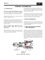
For pictorial clarity, some illustrations and Figures in this
manual may show shields, guards or plates open or removed.
Under no circumstances should your mower be operated
without these devices in place.
1.1 INTRODUCTION
Your mower was built to highest standards in the industry.
However, the prolonged life and maximum efficiency of
your mower depend on you following the operating,
maintenance and adjustment instructions in this manual.
All information is based upon product information available
at time of approval for printing. Scag Power Equipment
reserves the right to make changes at any time
without notice and without incurring any obligation.
If additional information or service is needed, contact your
Scag Power Equipment Dealer.
1.2 DIRECTION REFERENCE
We encourage you to contact your dealer for repairs. All
Scag dealers are informed of the latest methods to service
this equipment and provide prompt and efficient service in
the field or at their service shop. They carry a full line of
Scag service parts.
The “Right” and “Left”, “Front” and “Rear” of the machine
are referenced from the operator’s right and left when seated
in the normal operating position and facing the
forward travel direction.
USE OF OTHER THAN ORIGINAL SCAG
REPLACEMENT PARTS WILL VOID THE
WARRANTY.
1.3 SERVICING THE ENGINE AND DRIVE
TRAIN COMPONENTS
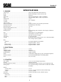
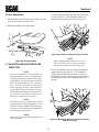
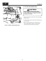
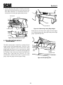
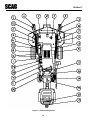
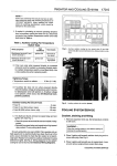
When ordering parts, always give the model and serial
number of your tractor and cutting deck. The serial plates
are located where shown in Figure 1-1.
The detail servicing and repair of the engine, hydraulic pump
and motors and gear boxes are not covered in this manual;
only routine maintenance and general service instructions
are provided. For service of these components during the
limited warranty period, it is important to contact your Scag
dealer or find a local authorized servicing agent of the
component manufacturer. Any unauthorized work done on
these components during the warranty period may void your
warranty.
Tractor Serial Number
Plate Location
Cutter Deck
Serial Number
Plate Location
Figure 1-1 Serial Plate Locations
1
Section 2
SAFETY INFORMATION
2.1 INTRODUCTION
Your mower is only as safe as the operator. Carelessness or
operator error may result in serious bodily injury or death.
Hazard control and accident prevention are dependent upon
the awareness, concern, prudence, and proper training of
the personnel involved in the operation, transport,
maintenance and storage of the equipment. Make sure every
operator is properly trained and thoroughly familiar with
all the controls before operating the mower.
The signal word “DANGER” denotes that an extremely
hazardous situation exists on or near the machine that could
result in high probability of death or irreparable injury if
proper precautions are not taken.
WARNING:
The signal word “WARNING” denotes a hazard exists on
or near the machine that can result in injury or death if
proper precautions are not taken.
READ THIS OPERATOR’S MANUAL BEFORE
ATTEMPTING TO START YOUR MOWER.
A replacement manual is available from your authorized
Scag Service Dealer or by Contacting Scag Power
Equipment, Service Department at P.O. Box 152, Mayville,
WI 53050. There is nominal charge of $2.00 for each
manual. Please indicate the complete model and serial
number of your Scag product.
CAUTION:
The signal word “CAUTION” is a reminder of safety
practices on or near the machine that could result in personal
injury if proper precautions are not taken.
2.2 SIGNAL WORDS
Your safety and the safety of others depend significantly
upon your knowledge and understanding of all correct
operating practices and procedures of this machine.
2.3 BEFORE OPERATION
CONSIDERATIONS
1. NEVER allow children to operate this riding
mower. Do not allow adults to operate this machine
without proper instructions.
This symbol means “Attention! Become Alert! Your
Safety is Involved!" The symbol is used with the
following signal words to attract your attention to safety
messages found on the decals and throughout this manual.
The message that follows the symbol contains important
information about safety. To avoid injury and possible
death, carefully read the message! Be sure to fully
understand the causes of possible injury or death.
2. DO NOT mow when children and/or others are
present.
3. Clear the area to be mowed of objects that could be
picked up and thrown by the cutter blades.
4. DO NOT carry passengers.
Signal Word:
5. DO NOT wear loose fitting clothing that could get
caught in moving parts. Do not operate the machine
wearing shorts; always wear adequate protective
clothing including long pants. Wearing safety glasses,
safety shoes and a helmet is advisable and is required
by some local ordinances and insurance regulations.
It is a distinctive word on safety decals and throughout
this manual that alerts the viewer to the existence and
relative degree of the hazard.
2
Section 2
6. Prolonged exposure to loud noise can cause hearing
impairment or loss. Operator hearing protection is
recommended, particularly for continuous operation of
the mower. Wear suitable hearing protection.
2.4 OPERATION CONSIDERATIONS
7. Keep the machine and attachments in good operating
condition. Keep all shields and safety devices in place.
If a shield, safety device or decal is defective or
damaged, repair or replace it before operating the
machine.
2. Reduce speed and exercise extreme caution on slopes
and in sharp turns to prevent tipping or loss of control.
Be especially cautious when changing directions on
slopes.
1. Know the function of all controls and how to stop
quickly.
WARNING:
WARNING:
This machine is equipped with an interlock
system intended to protect the operator and
others from injury. This is accomplished by
preventing the engine from starting unless the
parking brake is applied and the blades are
disengaged. The system also shuts off the
engine if the operator removes his foot from
the interlock pedal with the mower running and
the parking brake not engaged. Never operate
equipment with the interlock system disconnected or malfunctioning.
DO NOT operate on steep slopes. To check a slope,
attempt to drive up it (with cutter deck down). If
machine can drive up the slope without the wheels
slipping, reduce speed and use extreme caution.
ALWAYS FOLLOW OSHA APPROVED OPERATION.
3. Do not stop or start suddenly. WHEN GOING
UPHILL OR DOWN HILL, MOW UP AND
DOWN THE FACE OF SLOPES, NEVER
ACROSS THE FACE.
4. When using any attachment, never direct the discharge
of material toward bystanders nor allow anyone near
the machine while in operation.
8. Be sure interlock switches are functioning correctly
.
9. Fuel is flammable; handle with care.
5. Before attempting to start the engine, disengage power
to all attachments and engage the parking brake. DO
NOT depress the right foot pedal.
10.Equipment must comply with the latest requirements
per ANSI J137 and/or ANSI S279 when driven on
public roads.
6. If the mower discharge ever plugs, shut off the engine,
remove the ignition key, and wait for all movement to
stop before removing the obstruction.
11.DO NOT operate without a chute deflector installed;
keep the deflector in lowest possible position.
7. Be alert for holes, rocks, and roots in the terrain and
other hidden hazards. Keep away from any drop off.
Beware of overhead obstructions (low limbs, etc.),
underground obstacles (sprinklers, pipes, tree roots,
etc.). Cautiously enter a new area. Be alert for hidden
hazards.
12.Check the blade mounting bolts at frequent intervals
for proper tightness.
13.Make sure all hydraulic fluid connections are tight and
all hydraulic hoses and lines are in good condition
before starting the machine.
8. Disengage power to mower before backing up. Do not
mow in reverse unless absolutely necessary and then
only after observation of the entire area behind the
mower.
3
Section 2
9. DO NOT turn sharply. Use care when backing up.
2.5 MAINTENANCE CONSIDERATIONS
10.Use counterweights or wheel weights when suggested
in this manual.
1. Never make adjustments to the machine with the
engine running unless specifically instructed to do so.
If the engine is running, keep hands, feet, and clothing
away from moving parts.
11.Watch for traffic when crossing roads or operating
near roadways
.
12.Mow only in daylight or good artificial light.
2. Remove the key from the ignition switch to prevent
accidental starting of the engine when servicing or
adjusting the machine.
13.Take all possible precautions when leaving the machine unattended, such as disengaging the mower,
lowering the attachments, setting the parking brake,
stopping the engine, and removing the key.
3. Keep all nuts, bolts and screws tight to ensure the
machine is in safe working condition. Check blade
mounting bolts frequently to be sure they are tight.
14.Disengage power to the attachments when transporting or when not in use.
4. Do not change the engine governor settings or
overspeed the engine.
15.The machine and attachments should be stopped and
inspected for damage after striking a foreign object,
and damage should be repaired before restarting and
operating the machine.
5. To reduce fire hazard, keep the engine free of grass,
leaves, excessive grease and dirt.
6. Hydraulic fluid is under high pressure. Keep body
and hands away from pin holes or nozzles that eject
hydraulic fluid under high pressure. Use only cardboard or paper to search for leaks.
16.DO NOT touch the engine or the muffler while the
engine is running or immediately after stopping. These
areas may be hot enough to cause a burn.
7. Hydraulic fluid under high pressure may have sufficient force to penetrate skin and cause serious injury.
If hydraulic fluid is injected into the skin it must be
surgically removed within a few hours by a doctor or
gangrene may result.
4
Section 2
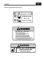
2.6 SAFETY AND INSTRUCTIONAL DECALS
DANGER
SPINNING BLADE
KEEP CLEAR
CONTACT CAN INJURE
48071
WARNING
ROTATING BLADES AND BELTS
KEEP HANDS, FEET & CLOTHING CLEAR
KEEP ALL GUARDS IN PLACE
SHUT OFF ENGINE & DISENGAGE BLADE
CLUTCH BEFORE SERVICING
CLEAR AREA OF DEBRIS BEFORE MOWING
USE CAUTION IN DIRECTING DISCHARGE
KEEP BYSTANDERS, CHILDREN & PETS AWAY
READ INSTRUCTION MANUAL BEFORE OPERATING
DO NOT OPERATE WITHOUT DISCHARGE CHUTE, MULCHING
481040
KIT, OR ENTIRE GRASS CATCHER INSTALLED
WARNING
INSTALL BELT COVER BEFORE
OPERATING MACHINE
READ OPERATOR'S MANUAL
5
481039
Section 3
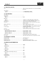
3.1 ENGINE
SPECIFICATIONS
General Type ............................................................................. Heavy Duty Industrial/Commercial Diesel
Brand ......................................................................................... Kubota 28 HP Super 5 Series, Electric Start
Model ......................................................................................... D1105-B
Horsepower ................................................................................ SAE Gross Intermittent, 28 HP @ 3000 RPM
Type ........................................................................................... Horizontal Shaft, Water Cooled, 4-Cycle Diesel
Displacement ............................................................................. 1123 cc.
Low Idle ..................................................................................... 850 - 950 RPM
Cylinders ................................................................................... 3
Order of Firing .......................................................................... 1-2-3
Direction of Rotation ................................................................. Counter-clockwise (Viewed From Flywheel End)
Fuel Injection Pump .................................................................. Bosch MD Type, Mini Pump
Injection Pressure ...................................................................... 1,991 psi
Injection Timing (Before T.D.C.) ............................................. 19°
Compression Ratio .................................................................... 23:1
Starting System ......................................................................... Electric Starting with Cell Starter, Glow Plug In Combustion
Chamber
Fuel ............................................................................................ Diesel Fuel No. 2 -D (ASTM D975)
Oil Type ..................................................................................... API Sandard, CD Grade or Better
Oil Filter .................................................................................... Full Flow Oil Filter Cartridge
Oil Capacity ............................................................................... 4 Quarts With Filter
Cooling
Pressurized, Sealed Cooling System, 170° F Thermostat, Blade
Fan, Cooling Capacity 8 Quarts
Belts:
Alternator .............................................................................. See Engine Manual for Part Number
Fan ......................................................................................... Scag Part Number - 481114
Electric Clutch ...................................................................... Scag Part Number - 481104
Hydraulic Pump .................................................................... Scag Part Number - 481103
3.2 ELECTRICAL
Battery ....................................................................................... 12 Volt
Charging System ....................................................................... Alternator
Charging Output ....................................................................... 12 Volt, 30 Amp
System Polarity .......................................................................... Negative Ground
Starter ........................................................................................ 12 Volt Electric Ring Gear Type, Key and Solenoid Operated
Interlock Switches ..................................................................... Left Foot Pedal, Blade Brake, and Parking Brake
Fuses .......................................................................................... Two (2) 30 Amp
3.3 TRACTOR
Drive Motors ............................................................................. 12 Cu. In. Cast Iron High Torque Motors
Steering ...................................................................................... Chain and Sprocket
Forward and Reverse Control ................................................... Pedal Operated Linkage Connected To The Hydraulic Pump
Parking Brake ............................................................................ Lever Actuated Linkage to Drum Brakes on Both Drive Wheel
Assemblies
Wheels:
(2) Front Caster .................................................................... 12 x 3.5
(2) Drive ............................................................................... 2 x 10.5 -12, 4-ply Pneumatic Tubeless, Radius Edge
(1) Rear ................................................................................ 18 x 8.50 -8 NHS
Fuel Tank ................................................................................... Seamless Polyethylene Tank; 8 Gallon Capacity
Tire Pressure:
Front Caster .......................................................................... 25 PSI
Drive ..................................................................................... 15 PSI
Rear ...................................................................................... 15 PSI
6
Section 3
3.3 TRACTOR (CONT'D)
Seat ............................................................................................ Milsco Seat With Adjustment Lever For Forward and Back
Movement
Travel Speed:
Forward ................................................................................ 0 - 8 MPH Infinitely Variable
Reverse ................................................................................. 0 - 4.3 MPH Infinitely Variable
3.4 CUTTER DECK
No. of Blades ............................................................................. 3
Width of Cut:
Mag-61 ................................................................................. 61 in.
Mag-72 ................................................................................. 72 in.
Blade Size:
Mag-61 ................................................................................. 1/4 thick x 21" long, milled edge, 5150 alloy steel
Mag-72 ................................................................................. 1/4 thick x 24-1/2" long, milled edge, 5150 alloy steel
Blade Spindles ........................................................................... Cast Iron with Easy Removable Taper Hubs
Deck Drive ................................................................................. Belt Driven Electric Clutch Connected to Drive Shaft to
Gearbox on Deck
Electric Clutch Type ................................................................. Warner “Mag Stop” Electric Clutch
Blade Brake ............................................................................... Lever Controlled Linkage to Band Type Brake. Brake Hub
Connected to Drive Shaft
Cutting Height ........................................................................... Switch on Instrument Panel Controls Electric Actuator;
Cutting Heights - 1-1/2" to 5-1/2"
Deck Tilt .................................................................................... Switch on Instrument Panel Controls Electric Actuator
Cutter Deck Belts:
Blade and Gearbox Drive (Mag-61) .................................... Scag Part Number - 48204
Blade and Gearbox Drive (Mag-72) .................................... Scag Part Number - 48089
Blade Drive (Mag-61) .......................................................... Scag Part Number - 48265
Blade Drive (Mag-72) .......................................................... Scag Part Number - 481295
Gearbox Type ............................................................................. Sealed Housing, Bevel Gear and Pinion Type
Drive Shaft ................................................................................ Quick-Disconnect Shaft With Two High Speed U-Joints
3.5 HYDRAULIC SYSTEM
Hydraulic Pump ......................................................................... Sunstrand Series 15
Hydraulic Cooler ....................................................................... Part of Radiator
Hydraulic Oil Filter ................................................................... 10 Micron Spin-on Element Type
Hydraulic Reservoir ................................................................... High Density Polyethylene; 13 Quart Capacity
3.6 WEIGHTS AND DIMENSIONS
Length:
Mag-61 ................................................................................. 120.0"
Mag-72 ................................................................................. 120.0"
Tracking Width:
Mag-61 ................................................................................. 54.0"
Mag-72 ................................................................................. 54.0"
Overall Width:
Mag-61 ................................................................................. 73.0"
Mag-72 ................................................................................. 84.0"
Overall Width (with Discharge Chute Up):
Mag-61 ................................................................................. 62.0"
Mag-72 ................................................................................. 73.0"
Overall Height ........................................................................... 51.0"
Operating Weight:
Mag-61 ................................................................................. 1,750 lb.
Mag-72 ................................................................................. 1,800 lb.
7
Section 4
OPERATING INSTRUCTIONS
Do not hold the key in the START position longer than
15 seconds. If the engine does not start, return the key
to the OFF position for at least 60 seconds before a
restart attempt is made. Prolonged cranking can
damage the starter motor and shorten battery life.
Release the key when the engine starts and it will
automatically return to the run position. To stop the
engine, rotate the key counter-clockwise to the OFF
position.
CAUTION:
Do not attempt to drive this mower unless you
have read this manual. Learn the location and
purpose of all controls and instruments before
you operate this mower.
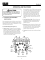
4.1 CONTROLS AND INSTRUMENT
IDENTIFICATION
2. Glow Plug Indicator Light: Yellow indicator turns
off when glow plugs have been properly energized
after the ignition switch is turned and held in the
PREHEAT position.
Before operating the mower, familiarize yourself with all
mower and engine controls. Knowing the location, function
and operation of these controls is important for safe and
efficient operation of the mower.
3. Hourmeter: Indicates the number of hours the engine
has been operated. It operates whenever the ignition
key is in the ON position. Can be used to keep track
of maintenance intervals and the amount of time
required to perform various tasks.
A. Instrument Panel (See Figure 4-1)
1. Ignition Switch: The ignition switch is used to start
and stop the engine and has four positions; PREHEAT,
OFF, ON, and START. Rotate the key to the PREHEAT position to energize the glow plug. Hold the
key at the PREHEAT position until the yellow indicator light for the glow plug turns off, then release and
rotate the key to the START position.
4. Voltmeter: Indicates the battery condition and charge
level.
6
6
5
Hourmeter
Fuel Gauge 4
Temperature Gauge
Voltmeter
Throttle
Lever
7
Engine
Oil Pressure
Switch
Blade
Brake
Control
Lever
Fuse
Holders 10
Mower
Deck Lift
Switch
Mower
Deck Height
Switch
8
9
Glow Plug
Indicator
Light 2
Ignition
Switch
Figure 4-1 Instrument Panel
8
1
Section 4
5. Temperature Gauge: Indicates engine coolant
temperatures. Green zone indicates proper working
temperature. Red zone indicates engine over heating
and the engine should be shut off immediately.
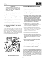
Parking Brake
Lever
6. Fuel Gauge: Indicates the amount of fuel in the fuel
tank.
7. Engine Oil Pressure Indicator Light: Indicator will
light if oil pressure drops below a safe operating
pressure. Stop the engine immediately; determine the
cause and correct the problem before continuing
operation.
Forward/Reverse
Foot Pedal
8. Mower Deck Lift Switch: This switch raises and
lowers the deck for road travel, etc. Pushing the
switch forward tilts the mower deck back. Pulling the
switch back tilts the deck forward.
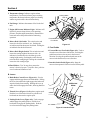
Figure 4-2
C. Foot Pedals
1. Forward/Reverse Foot Pedal (Figure 4-2): Used to
select the travel direction of the mower. Pressing the
pedal forward moves the mower in the forward
direction. Pressing the pedal backwards moves the
mower in the backward (reverse) direction.
9. Mower Deck Height Switch: This switch raises and
lowers the cutting height of the mower deck. An
indicator is located above the deck that gives the
cutting height setting. Pushing the switch forward
raises the deck cutting height. Pulling the switch back
lowers the deck cutting height.
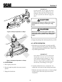
2. Interlock Switch Pedal (Figure 4-3): Stops the
mower when operator's left foot in raised off the pedal.
10.Fuse Holders: Two 30 amp fuses protect the
mower’s electrical system. To replace fuses, pull fuse
out of socket and install new fuse.
B. Levers
1. Blade Brake Control Lever (Figure 4-1): Used to
engage and disengage the mower blade brake. Pulling
the lever down and to the right engages the brake and
stops the blades from rotating. Pushing the lever up
and to the left disengages the brake, allowing blades to
rotate.
INTERLOCK
PEDAL
2. Throttle Lever (Figure 4-1): Regulates engine speed.
Push the lever forward to increase or pull the lever
backwards to decrease the engine speed.
3. Parking Brake Lever (Figure 4-2): Used to engage
and disengage the parking brakes. Pull the lever
backwards to engage the parking brake. Push the
lever forward to disengage the parking brake.
Figure 4-3 Interlock Pedal
9
Section 4
4.2 SAFETY INTERLOCK SYSTEM
4.3 INITIAL RUN-IN PROCEDURES (First
Day of Use or Approximately 10 Hours)
This mower is equipped with a safety system that prevents
the engine from starting unless the mower blade brake is
disengaged and parking brake is engaged. The system also
shuts the engine off if the operator's left foot is raised from
the interlock pedal with the mower and parking brakes
disengaged.
1. Check all belts for proper tension at 2, 4 and 8 hours;
adjust as needed.
2. Check the neutral adjustment. If necessary, adjust the
linkage so that the mower does not move when forward
and reverse pedal is in neutral (See Adjustments in
Section 6).
WARNING:
3. Check the tires for proper inflation (See Section 7-2).
Never operate the mower with the interlock
system disconnected or malfunctioning. Do not
disconnect or bypass any switch; injury to
yourself and others or property damage could
result.
4. Check for loose hardware. Tighten as needed.
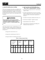
5. Perform Interlock Tests in Table 4-1.
6. Apply lubricant to all machine grease fittings. See
Lubrication Chart in Section 7.2.
If the safety interlock system is malfunctioning or if you
want to ensure that it is working properly, perform the tests
in Table 4-1. Stop the test and have the system inspected
and repaired if:
• the engine does not start in test 1, or
• the engine does start during tests 2 and 3, or
• the engine continues to run during tests 4 and 5.
Table 4-1 Interlock System Tests
Left Foot
Lifted From
Interlock
Pedal
Test Yes
1
2
3
4
5
X
X
X
Parking
Brake
Brake
No
On
X
X
X
X
Off
X
X
X
10
Mower
Blade
On
Off
Yes
X
X
X
X
X
X
Engine
Operates
No
X
X
X
X
Section 4
4.4 DIESEL ENGINE BREAK-IN
The proper break-in of a new diesel engine can make a
difference in the performance and life of the engine. Perform
the following break-in procedure during the first 50 hours
of operation:
1. A new engine should be operated with as near full load
as possible. However, the engine must be allowed to
reach an operating temperature before operating at full
load conditions.
2. The engine oil should be checked twice daily. Higher
than normal oil consumption is not uncommon during
the initial break-in period.
3. Change the oil and filter element after the first 40
hours of operation.
4. Check all engine belts for proper tension after the first
10 hours of operation and adjust, if necessary. Refer
to Adjustments in Section 6.
5. During the break-in period, check and tighten all
engine hardware.
4. Turn the ignition key switch to the PREHEAT position
until the indicator light for the glow plug glows bright
red. The colder the temperature, the longer it will take
to energize the glow plug. This step is not necessary
when starting a warm engine.
5. Turn the ignition key switch to START position and
release the key as soon as the engine starts. Do not
hold the key in the START position for more than 15
seconds at a time. Allow at least 60 seconds between
each cranking attempt to inhibit overheating the starter
motor. Prolonged cranking can damage the starter
motor and shorten battery life.
6. Allow engine to warm to operating temperature.
4.6 OPERATOR COMFORT ADJUSTMENTS
Two adjustments can be made to make your mowing job
comfortable. The steering handle can be adjusted up or
down and the seat can be adjusted forward or back.
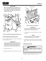
A. Adjusting Steering Handle Height
1. Remove the hardware securing the handle to the
steering shaft. Two sets of holes are available to
adjust the handle height.
4.5 STARTING THE DIESEL ENGINE
CAUTION:
DO NOT USE STARTING FLUIDS. Use of starting
fluids in the air intake system may be potentially
explosive or cause “Runaway” engine condition
that could result in engine damage and/or
personal injury.
Hardware
Second Bolt Hole
1. Be sure the fuel shut-off valve is completely open.
The valve is located in the fuel line between the fuel
tank and electric fuel pump (See Section 7).
Figure 4-4 Steering Handle Adjustment
2. Sit in the operator’s seat and depress the interlock foot
pedal with your left foot. Make sure the parking brake
and mower blade brake are engaged.
2. Move the handle to align with the other holes in the
steering shaft. Install the hardware and tighten.
3. Set throttle lever to 3/4 throttle.
11
Section 4
B. Seat Adjustment
1. To travel forward, depress the right foot pedal at the
toe. (See Figure 4-6). The further the pedal is depressed the faster the mower will travel forward.
1. Pull the handle on the left side of seat (Figure 4-5) and
move the seat either forward or back.
2. Release the handle to lock the position.
Figure 4-6 Forward - Depress Toe End of Pedal
-NOTEBefore shifting from forward to reverse, or reverse to forward, come to complete stop then
shift the foot pedal to the desired direction.
Figure 4-5 Seat Adjustment
4.7 ADJUSTING GROUND SPEED AND
DIRECTION
2. To travel backwards (reverse), depress the right foot
pedal at the heel (See Figure 4-7). The further the
pedal is depressed the faster the mower will travel
backwards. Use slower traveling speed when traveling
backwards and observe the area behind you before
moving.
-NOTEIf you are not familiar with the operation of
the hydrostatic drive, practice turning and maneuvering with the foot controls before engaging the blades. Learn the operation in an open
area away from buildings, fences, or obstructions. Learn the operation on a flat ground
before operating on slopes. Start maneuvering with SLOW engine speed until you are familiar with all operating characteristics. Practice maneuvering the mower until you can
make it go exactly where you intend.
-NOTEIf the mower is driven on public roads, it must
comply with state and local ordinances as well
as SAE J137 and/or ASME S279 requirements.
Contact your local authorities for regulations
and equipment requirements.
-NOTEThe left operator foot pedal must be depressed
before operation.
Figure 4-7 Backward (Reverse) Operation- Depress
Heel End of Pedal
12
Section 4
4. When traveling, the throttle control can be adjusted to
increase or decrease travel speed.
3. Always operate the engine at full throttle to
properly maintain cutting speeds. If the engine
starts to lug down, reduce the forward speed to
allow the engine to operate at maximum RPM.
5. Reduce speed when turning around trees, shrubs, etc.
4.9 HILLSIDE OPERATION
3. Check that all systems function correctly.
WARNING:
IMPORTANT:
Avoid high-speed turns on all surfaces. Tires
can slip on grass and can wear rapidly on
concrete and asphalt.
To minimize the possibility of overturning, the
least dangerous method of operating on hills
and terraces is to travel vertically up and down
the slope, not horizontally along the slope.
Avoid any unnecessary turns and travel at
reduced speed.
6. When going over curbs, first activate the mower deck
lift switch to fully raise the deck to clear the curb. Go
FORWARD over the curb.
4.8 ENGAGING THE MOWER
1. Set engine throttle about 1/2 speed. Do not attempt
to engage the blade at high engine speed as this
shortens the electric clutch life — use only moderate
engine speed when engaging the blades.
2. Engage the mower blades by moving the blade brake
lever down and to the right.
1. The mower has been designed for good traction and
stability under normal mowing conditions. However,
caution must be used when traveling on slopes,
especially when the grass is wet. Wet grass limits
traction and steering control.
2. To inhibit tipping or loss of control, do not start or
stop suddenly, avoid unnecessary turns and travel at a
reduced speed.
3. Keep tires properly inflated.
WARNING:
A safety interlock switch (left foot pedal) will
cause the engine to stop if the blade brake
is disengaged, and the left foot pedal is not
depressed. The function of the switch
should be checked by the operator raising
his left foot and disengaging the blade
brake; the engine should stop. If the switch
is not working, it should be repaired or
replaced before operating the mower. Do
not disconnect the interlock safety switches
because they are for the operator’s protection.
4. Always travel up or down the slope, whenever possible; NEVER across the slope.
5. If the mower cannot climb the slope, the grade is too
steep for safe operation. Do not make another attempt
to climb the slope. Engage the blade brake to stop the
blades and back down slowly.
-IMPORTANTDo not engage the mower blades when
transporting the mower across drives, loose
materials, etc.
13
Section 4
-IMPORTANTIf at all possible, do not engage the mower
brake with engine running at high speed, since
premature wear of the electric clutch will occur. Lower speed to near idle then engage the
brake.
CAUTION:
The blade brake stops the blades from rotating.
If the blades do not stop, contact your Scag
Dealer.
CAUTION:
Remove the key from the ignition switch when
leaving the mower unattended to inhibit children
and inexperienced operators from starting the
engine.
Figure 4-8 Proper Operation on Slope
4. Engage the parking brake and turn ignition key to OFF.
4.11 AFTER OPERATION
1. Park the mower on a flat and level surface and fully
lower the cutting deck to the ground. Stop the engine
and engage the parking and blade brakes. Remove the
key from the ignition switch.
-IMPORTANTIf the radiator dirt screen is not removed and
cleaned after every use, the screen will become clogged with grass clippings, etc., blocking the air flow through the radiator. This
will cause a high engine operating temperature that may cause damage to the engine.
Figure 4-9 Improper Operation on Slope
4.10 STOPPING
1. Slow engine speed to idle.
2. Clean the radiator dirt screen. See Section 7 for
radiator dirt screen removal and cleaning instructions..
2. Place the right foot pedal in the center (neutral)
position.
3. Wash the entire mower after each use. Do not use high
pressure spray or direct the spray onto electrical
components.
3. Engage the blade brake.
14
Section 4
-IMPORTANTDo not wash a hot or running engine. Use
compressed air to clean the engine and the
radiator fins. Cold water will damage the
engine and/or radiator.
4. Keep the entire mower clean to inhibit serious heat
damage to the engine or hydraulic oil circuit.
5. Recheck the cutter drive belts for proper tension,
alignment and any signs of rubbing. Correct and adjust
as necessary.
6. Fill the fuel tank with fresh, clean fuel at the end of
every day of operation.
7. Check the tire pressure. Inflate tires if necessary.
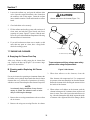
4.12 MOVING MOWER WITH THE ENGINE
STOPPED
To “free-wheel” or move the mower around without the
engine running, rotate the dump valve handle (screw and
nut) located on the side of the hydraulic pump to full open
position. See Figure 4-10. Disengage the parking brake
and move the mower by hand. The lever must be returned
to the original position to operate the mower.
4.13 RECOMMENDATIONS FOR MOWING
1. Keep the mower deck and discharge chute clean.
2. Mow with sharp blades. A dull blade will tear grass,
resulting in poor lawn appearance and takes extra
power (slow mowing speed).
3. The discharge deflector must not be removed and must
be kept in the lowest position to deflect grass clippings
and thrown objects downward. Orient the side discharge away from sidewalks or street to minimize
cleanup of clippings. When mowing close to obstacles,
orient the discharge away from obstacles to reduce the
chance of property damage by thrown objects.
4. Cut grass when it is dry and not too tall. Mow
frequently and do not cut grass too short (cut off 1/3
or less of existing grass for best appearance).
5. Operate the engine at or near full throttle for best
cutting. Mowing with a lower RPM causes the mower
to not cut clean and tear the grass. The engine is
designed to be operated at full speed.
6. Use slow travel speed for trimming purposes.
7. When mowing tall or wet grass, mow the grass twice.
Raise the mower to the highest setting for the first pass
and then make a second cutting pass to the desired
height.
8. Be sure the mower is leveled properly for a smooth
cut. See Section 7, Adjustments.
Dump Valve
Handle
Open
9. Use alternate stripe mowing pattern for best appearance and vary the direction of the stripe each time the
grass is mowed to avoid wear patterns in the grass.
Close
4.14 ADJUSTING CUTTING HEIGHT
Figure 4-10 Dump Valve Handle
The mower deck height switch on the instrument panel is
used to adjust the cutting height of the deck. Do not adjust
the cutting height while the mower is moving. Stop the
mower, then activate the deck height switch to position the
deck at the desired height. A gauge is located on the right
front of the mower (See Figure 4-11) for use in selecting
the proper cutting height.
15
Section 4
4.15 TILTING THE MOWER DECK
CAUTION:
1
2
3
4
Do not tilt the deck with the mower blades
rotating. Engage the blade brake before tilting
the deck. Bodily injury or damage to the mower
or property could result.
1. Stop the traveling movement of the mower and engage
the blade brake.
2. Use the deck tilt control switch on the instrument panel
to raise the deck.
3. Before lowering the deck, observe that there are no
objects under the deck. Remove any objects then,
activate the deck tilt switch to lower the deck.
Figure 4-11 Mower Cutting Height Gauge
16
Section 5
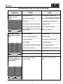
TROUBLESHOOTING CUTTING CONDITIONS
CAUSE
CONDITION
Stringers - Occasional
Blades of Uncut
Grass
CURE
Low engine RPM
Run engine at full 3600 RPM
Ground speed too fast
Slow speed to adjust for conditions
Wet grass
Cut grass after it has dried out
Dull blades, incorrect sharpening
Sharpen blades
Deck plugged, grass accumulation Clean underside of deck
Width of Deck
Belts slipping
Adjust belt tensions
Dull, worn blades
Sharpen blades
Incorrect blade sharpening
Sharpen blades
Low engine RPM
Run engine at full 3600 RPM
Belt slipping
Adjust belt tension
SGB020
Streaking - Strips of
Uncut Grass in Cutting
Path
Deck plugged, grass accumulation Clean underside of deck
Width of Deck
Ground speed too fast
Slow speed to adjust for conditions
Wet grass
Cut grass after it has dried out
Bent blades
Replace blades
Not enough overlapping
between rows
Increase the overlap of each
pass
SGB018
Streaking - Strips of
Uncut Grass Between
Cutting Paths
Width
of
Deck
SGB019
Width
of
Deck
17
Section 5
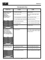
TROUBLESHOOTING
CAUSE
CONDITION
Uneven Cut on Flat
Ground - Wavy
High-Low
Appearance,
Scalloped Cut, or
Rough Contour
CURE
Lift worn off of blade
Replace blade
Blade upside down
Mount with cutting edge toward
ground
Deck plugged,grass accumulation
Clean underside of deck
Too much blade angle (deck pitch) Adjust pitch and level
Deck mounted improperly
See your authorized SCAG dealer
Bent spindle area
See your authorized SCAG dealer
Dull blade
Sharpen blade
Uneven ground
May need to reduce ground speed,
raise cutting height, and/or change
direction of cut
Tire pressures not equal
Check and adjust tire pressure
Wheels uneven
Check and adjust tire pressure
Deck mounted incorrectly
See your authorized SCAG dealer
Width of Deck
SGB020
Uneven Cut on
Uneven Ground Wavy Appearance,
High-Low Scalloped
Cut, or Rough Contour
Width of Deck
SGB021
Sloping Ridge Across
Width of Cutting Path
Width of Deck
SGB023
18
Section 5
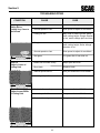
TROUBLESHOOTING
CAUSE
CONDITION
Scalping - Blades
Hitting Dirt or
Cutting Very Close to
the Ground
Width of Deck
CURE
Low tire pressures
Check and adjust pressures
Ground speed too fast
Slow speed to adjust for conditions
Cutting too low
May need to reduce ground speed,
raise cutting height, change direction
of cut, and/or change pitch and level
Rough terrain
May need to reduce ground speed,
raise cutting height, and/or change
direction of cut
Ground speed too fast
Slow speed to adjust for conditions
Wet grass
Cut grass after it has dried out
Blades not mounted evenly
Adjust pitch and level
Bent blade
Replace blade
Internal spindle failure
See your authorized SCAG dealer
Mounting of spindle incorrect
See your authorized SCAG dealer
Bent spindle mounting area
See your authorized SCAG dealer
Internal spindle failure
See your authorized SCAG dealer
Bent deck housing
See your authorized SCAG dealer
SGB022
Step Cut
Ridge in Center of
Cutting Path
Width of Deck
SGB024
Slope Cut - Sloping
Ridges Across Width
of Cutting Path
Width of Deck
SGB025
19
Section 6
ADJUSTMENTS
6.2 FORWARD/REVERSE NEUTRAL
ADJUSTMENT
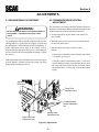
6.1 PARKING BRAKE ADJUSTMENT
The forward/reverse linkage should be adjusted whenever
the mower will not stay stationary when the forward/reverse
(right) foot pedal is placed in the neutral position.
WARNING:
Do not operate the mower if the parking brake is
not operable. Possible severe injury could
result.
1. Set the engine deck on jack stands so the wheels are
free to rotate.
The parking brake linkage should be adjusted whenever the
parking brake lever is placed in the “Engage” position and
the parking brake will not hold the mower from moving. A
minor adjustment can be made at the control lever by
loosening the jam nut shown in Figure 6-1 and turning the
rod in a clockwise direction to tighten the linkage. Tighten
the jam nut.
2. Block the caster wheels to prevent an accident should
the unit fall off the jacks.
3. Start the engine and observe for drive wheel
rotation.
If the wheels consistently rotate when the foot control
is in neutral, go to step 4.
If this adjustment does not hold the mower from moving or
no more thread is available on the rod, contact your Scag
dealer before operating the mower.
If the drive wheels intermittently rotate, i.e. the drive
wheels sometimes rotate and sometimes do not when
the foot pedal is not depressed, then check the neutral
adjustment bolt for “zero free play” in the neutral control
spring.
Adjustment
Dimension
Pump Drive
Adjustment Nut
1/4"
Forward/Reverse
Neutral Adjustment
Nut
Parking Brake
Adjustment Nuts
Right Foot Pedal
Adjustment Nuts
Figure 6-1 Adjustments
20
Section 6
-NOTEIf you turn the nut too much, you will compress the spring, making too much end play.
Go to step 4.
4. If the drive wheels rotate in rearward travel direction,
turn the adjustment bolt (Figure 6-1) clockwise until
rotation stops. If the drive wheels rotate in the forward travel direction, turn the adjusting bolt counterclockwise until rotation stops.
5. Check the adjustment of the right foot pedal for full
forward speed. The bottom of the foot pedal should be
1/4 inch from the top of the foot plate (See Figure 6-1)
when the pump is stroked in the full forward position.
To make an adjustment, loosen the jam nut at the
pump control bellcrank (Figure 6-1). Depress the foot
pedal and turn the control rod until 1/4 inch is obtained
between the bottom of the foot pedal and the top of the
foot plate. Tighten the jam nut.
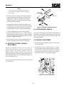
Locknut
Bolt
Figure 6-2 Throttle Control Adjustment
6.4 CUTTER BRAKE LINKAGE
The cutter brake linkage is self-adjusting. If the brake will
not hold the cutter blades from turning, consult your Scag
dealer. Do not operate the mower if the cutter brake is not
functioning properly.
6. Start the engine. The drive wheels should rotate only
when the forward/reverse foot pedal is depressed.
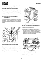
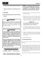
6.5 FAN BELT ADJUSTMENT
6.3 THROTTLE CONTROL LINKAGE
ADJUSTMENT
1. Remove the pump belt guard to gain access to the fan
drive idler bracket.
Should the throttle control lever not stay in
position after moving it to increase or decrease the
engine speed, the throttle linkage must be
tightened. Hold the lock nut (Figure 6-2) with a wrench
while turning the bolt clockwise to tighten the throttle lever
against the friction plate. Do not overtighten as the control
lever will be hard to move.
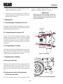
2. Loosen the two bolts (A and B, Figure 6-3). Using a
3/8 inch ratchet wrench installed in hole C, rotate the
bracket until 1/2 inch deflection in the belt is observed
using 10 pounds of pressure on the belt. See Engine
Drive Belts, section 7.9 for checking method.
A
If the engine speed must be increased or decreased, consult
your Scag dealer.
B
C
Figure 6-3 Fan Belt Adjustment
21
Section 6
3. After proper tension is obtained, tighten the two bolts
and install the pump belt guard.
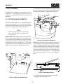
Adjusting Bolt
6.6 PUMP DRIVE BELT ADJUSTMENT
To adjust belt tension, turn the adjusting nut (Figure 6-1)
until 1/2 inch deflection in belt is obtained with 10 pounds
of pressure. See Engine Drive Belts, section 7.9 for checking
method.
6.7 ELECTRIC CLUTCH DRIVE BELT
ADJUSTMENT
To adjust the belt tension, turn the adjusting nut (Figure 64) to obtain 1/2 inch belt deflection with 10 pounds of
pressure. See Engine Drive Belts, section 7.9 for checking
method.
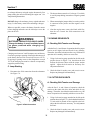
Adjusting Bolt
Location
Figure 6-5 Alternator Belt Adjustment
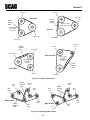
6.9 CUTTER DRIVE BELT ADJUSTMENTS
1. Remove the top cutter deck cover.
2. Each belt has an adjustment rod attached to its belt
idler arm. To adjust the belt tension, turn the adjusting
nut (Figure 6-6) until 1/2 inch deflection in the belt is
obtained with 10 pounds of pressure. See Cutter Deck
Belts, section 7-10 for checking method.
Figure 6-4 Electric Clutch Drive Belt Adjustment
6.8 ALTERNATOR BELT ADJUSTMENT
To adjust the alternator belt tension, loosen the two bolts
holding the alternator (Figure 6-5). Move the alternator
until proper tension of 0.28 to 0.35 inch deflection with 22
pounds of pressure is obtained, then tighten the two bolts.
See Engine Drive Belts, section 7.9 for checking method.
Tension Adjusting Nuts
Figure 6-6 Blade Belt Tension Adjustments
(Mag-72 Deck Shown)
3. Replace the top cutter deck cover.
22
Section 6
6.10 BELT ALIGNMENT
Belt alignment is important for proper performance of your
Scag mower. If you experience frequent belt wear or
breakage, see your authorized Scag service dealer for belt
adjustment.
To level the deck, loosen the adjusting nut (Figure 6-8) and
lift or lower the deck until the left side measurement equals
the right side measurement. Tighten the adjusting nut.
6.11 CUTTER DECK ADJUSTMENTS
Due to many conditions that exist, it is difficult to suggest a
setting that will work for every lawn. However, two
adjustments should be made on the cutter deck to ensure
proper grass cutting: DECK LEVEL AND PITCH.
-NOTEBefore checking for proper cutter deck adjustments, check that all tires are inflated to the
correct pressure.
DECK LEVEL is the adjustment to level the deck side-toside. For proper blade cutting, the deck should be level.
To check for level, place the mower on a flat, level surface.
On the right side of the deck, measure from the ground to
the bottom of the cutter deck (Figure 6-7). Then, take a
measurement on the left side of the deck. Both measurements
should be equal. If different, adjust the deck to level.
Adjusting Nut
Figure 6-8 Leveling the Cutter Deck
PITCH is the adjustment to angle the blades from rear to
front. For proper grass cutting, the blades should be angled
forward. To check proper blade pitch, place the mower on
a flat, level surface. Measure the distance from the ground
to the rear of the mower deck ("X", Figure 6-9). Then,
measure on both sides of the mower deck the distance from
the ground to the front of the deck ("Y"). The front should
be 1/4 inch lower than the rear. If not correct, adjust the
pitch.
="Y"
"X"=
Figure 6-9 Pitch Measurement
Figure 6-7 Measuring Height of Deck
1. To adjust the pitch, loosen the jam nut on both
adjusting rods (See Figure 6-10).
23
Section 6
2. Turn the adjusting rods counter-clockwise to lower the
front of the deck and clockwise to raise the front of the
deck. When a difference of 1/4 inch from front to rear
is obtained on left and right, tighten both jam nuts.
Adjusting Nut
Jam Nut
Blade
1
2
3
4
Tape Measure
Figure 6-11 Measuring Cutting Edge Height
Adjusting Rod
Loosen the two jam nuts on the gauge rod (See Figure
6-12). Slide the gauge rod to the proper setting on the height
gauge. Tighten the jam nuts.
Figure 6-10 Adjusting Deck Pitch
6.12 BLADE CUTTING HEIGHT
ADJUSTMENT
The blade cutting height is adjusted by actuating the deck
height switch on the instrument panel. However, if the
cutting height compared to what is shown on the cutting
height gauge (See Figure 6-12) is in question, the cutting
height should be checked. To check the cutting height, lift
the discharge chute and measure from the ground to the
cutting edge of the blade (See Figure 6-11). If the
measurement is different from what is registered on the
gauge, adjust the gauge rod to the proper setting.
Adjusting
Nuts
Height
Indicator Rod
Figure 6-12 Adjusting Nuts
24
Section 7
MAINTENANCE
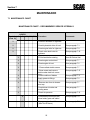
7.1 MAINTENANCE CHART
MAINTENANCE CHART - RECOMMENDED SERVICE INTERVALS
Break-In
(First 10)
8
HOURS
40 100 200 500
Procedure
Comments
X
Check all hardware for tightness
X
Check hydrostatic drive oil level
See paragraph 7.3
X
Check engine belts for tightness
See paragraph 7.9
X
Check cutter deck belts for
tightness
See paragraph 7.10
X
Fill fuel tank before starting
Use #2-D diesel fuel
X
Check engine coolant level
See paragraph 7.7
X
Check engine oil level
See paragraph 7.5
X
**Clean radiator debris screen
See paragraph 7.7
X
*Clean mower and remove
debris under deck belt covers
See paragraph 7.13
X
Check condition of blades
See paragraph 7.11
X
Apply grease to fittings
See paragraph 7.2
X
*Remove dust from air cleaner
dust cup
See paragraph 7.7
X
Check/clean air intake and
cooling areas
See paragraph 7.7
X
Check tire pressure
See paragraph 7.12
X
Check battery electrolyte level,
clean battery post and cables
See paragraph 7.8
X
Change engine oil and filter
(After first 40 hours)
See paragraph 7.5
25
Section 7
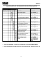
MAINTENANCE CHART - RECOMMENDED SERVICE INTERVALS (CONT'D)
Break-In
(First 10)
*
HOURS
8
40 100 200 500
Procedure
Comments
X
Apply grease to fittings
See paragraph 7.2
X
Change engine oil
See paragraph 7.5
X
Clean air cleaner element
See paragraph 7.7
X
Check engine belts for tightness
See paragraph 7.9
X
Check cutter deck belts for
tightness
See paragraph 7.10
X
Apply grease to fittings
See paragraph 7.2
X
Check hardware for tightness
X
Change engine oil filter
See paragraph 7.5
X
Check hydrostatic drive fluid
level
See paragraph 7.3
X
Grease rear wheel bearing
See paragraph 7.2
X
Replace engine fuel filter
cartridge and pre-filter
See paragraph 7.6
X
Drain hydrostatic drive system
and replace hydraulic oil
See paragraph 7.3
Use SAE 10W30 Oil
X
Replace hydraulic oil filter
See paragraph 7.3
X
Drain and replace engine
coolant
See paragraph 7.7
Use 50/50 water and
ethylene glycol antifreeze
Perform these maintenance procedures more frequently under extreme dusty or dirty conditions
** Perform this maintenance procedure whenever the engine temperature gauge indicator is in the red zone
26
Section 7
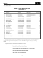
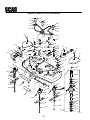
7.2 LUBRICATION
GREASE FITTING LUBRICATION CHART
(SEE FIGURE 7-1)
LUBRICATION
NO.
LOCATION
INTERVAL
LUBRICANT
OF PLACES
1. Cutter Drive Spindle
2. Cutter Deck Spindles
40 Hours/Weekly
40 Hours/Weekly
+Lithium MP White Grease 2125
+Lithium MP White Grease 2125
1
3
3. Caster Wheel Bearing
100 Hours/Bi-Monthly
Chassis Grease
2
4. Caster Wheel Pivot
100 Hours/Bi-Monthly
Chassis Grease
2
5. Electric Clutch Belt Idler Arm
100 Hours/Bi-Monthly
Chassis Grease
1
6. Cutter Drive Shaft
100 Hours/Bi-Monthly
Chassis Grease
3
7. Cutter Belt Idler Arms
100 Hours/Bi-Monthly
Chassis Grease
2
8. Deck Support Pivot
100 Hours/Bi-Monthly
Chassis Grease
2
9. Deck Push Arms
100 Hours/ Bi-Monthly
Chassis Grease
2
10. Deck Lift Bellcranks
100 Hours/Bi-Monthly
Chassis Grease
4
11. Pump Idler Arm
100 HoursBi-Monthly
Chassis Grease
1
12. Rear Wheel Pivot
200 Hours/Monthly
Chassis Grease
1
13. Rear Wheel Bearings
200 Hours/Monthly
+Lithium MP White Grease 2125
1
14. Right Hand Foot Plate Pivot
200 Hours/Monthly
Chassis Grease
1
15. Steering Handle
200 Hours/Monthly
Chassis Grease
1
16. Throttle Lever
200 Hours/Monthly
Chassis Grease
1
17. Parking Brake Lever
200 Hours/Monthly
Chassis Grease
1
18. Blade Brake Linkage Lever
200 Hours/Monthly
Chassis Grease
1
19. Blade Brake Linkage Bellcrank
200 Hours/Monthly
Chassis Grease
1
20. Blade Brake Control Lever
200 Hours/Monthly
Chassis Grease
1
* Lubrication may be required every 8 to 40 hours, depending on climate and environment. Apply two
pumps of hand gun when lubricating these locations. DO NOT over-grease; damage to seal may
occur.
+
Compatible Greases: Mobilix #2 found at Mobil Service Station
Ronex MP found at Exxon Service Stations
Super Lube MEP #2 & Super Stay-M #2 found at Conoco Station
Shell Alvania #2 found at Shell Service Station
Lidok EP #2 found at industrial shops
27
Section 7
Figure 7.1 Grease Fitting Points
28
Section 7
7.3 HYDROSTATIC DRIVE SYSTEM
B. Changing Hydraulic Oil
A. Checking Hydraulic Oil Level
The hydraulic oil should be changed after every 500 hours
or annually, whichever occurs first. The oil should also be
changed if the color of the fluid has become black or milky.
A black color and/or a rancid oder usually indicates possible
overheating of the oil, and a milky color usually indicates
water in the hydraulic oil.
The hydrostatic drive oil level should be checked after the
first 10 hours of operation. Thereafter, check the oil after
every 200 hours of machine operation or monthly, whichever
occurs first.
-NOTEThe hydraulic oil should be changed every
time there is a major hydraulic component failure, or if you notice the presence of water or a
rancid odor to the hydraulic oil.
-IMPORTANTIf the oil level is consistently low, check for
leaks and correct immediately.
1. Wipe dirt and contaminants from around the reservoir
cap. Remove the cap from the hydraulic oil reservoir.
1. Park the mower on a level surface and stop the engine.
2. Visually check the level of hydraulic oil. Hydraulic oil
must be at least 3 inches from bottom of fill port. See
Figure 7-2. If the level cannot be determined visually,
use a clean tape measure to check the level. If the
fluid is low, add recommended fluid. DO NOT overfill;
fluid level more than 3 inches below the bottom of the
fill port will spill from the reservoir.
2. Place a suitable container under the hydraulic oil filter.
Remove the cap from the tee installed in the hydraulic
oil filter head. See Figure 7-2. Allow the fluid to drain
into the container.
3. Install the cap onto the tee and be sure it is tight.
4. Remove fill cap from reservoir and fill reservoir to 3
inches below fill port opening with recommended oil.
3. Clean the cap and install it onto the reservoir.
5. Start the engine and propel mower a few feet to fill all
the lines, pump, and motors with oil and to remove any
air in the system. Check the oil level in the reservoir.
If necessary, fill it to within 3 inches from the bottom
of the fill opening with SAE 10W30 motor oil.
Fill Cap and Port
Hydraulic Oil
Reservoir
6. Replace the reservoir fill cap.
Hydraulic Oil
Filter
C. Changing Hydraulic Oil Filter Element
Drain Port Tee
Location
The hydraulic oil filter should be changed after every 500
hours of operation or annually, whichever occurs first.
1. Remove the oil filter element and discard. Fill the new
filter with clean oil. See Figure 7-2.
Figure 7-2 Hydraulic Oil Level
2. Install the new filter element. Hand tighten only.
29
Section 7
3. Run the engine at idle speed with the hydrostatic drive
system in neutral for five minutes.
(Figure 7-4) should be replaced after every 500 hours of
operation or annually, whichever occurs first.
4. Check the oil level in the hydraulic tank. It must be 3
inches from the bottom of the fill opening. If necessary,
add SAE 10W30 motor oil.
-IMPORTANTReplace the fuel filter cartridge and the prefilter periodically to prevent wear of the fuel
injection pump plunger or the injection nozzle
due to dirt in the fuel.
7.4 ENGINE OIL
A. Checking Engine Crankcase Oil Level
The engine oil level should be checked after every 8 hours
of operation or daily as instructed in the Engine Operator’s
Manual furnished with this mower.
Fuel Filter
Location
B. Changing Engine Crankcase Oil
After the first 40 hours of operation, change the engine
crankcase oil and replace the oil filter. Thereafter, change
the engine crankcase oil after every 100 hours of operation
or bi-weekly, whichever occurs first. Refer to the Engine
Operator’s Manual furnished with this mower for
instructions.
C. Changing Engine Oil Filter
After the first 40 hours of operation replace the engine oil
filter. Thereafter, replace the oil filter after every 200 hours
of operation or every month, whichever occurs first. Refer
to Engine Operator’s Manual for instructions.
Figure 7-3 Fuel Filter
7.5 ENGINE FUEL SYSTEM
A. Filling the Fuel Tank
Fill the fuel tank at the end of each operating day to within
1 inch below the filler neck. Do not overfill and never
allow the tank to become completely empty. Use clean,
fresh No. 2 diesel fuel with a minimum Cetane Rating of
45.
Pre-Filter
B. Replacing In-Line Fuel Filter Element
and the Fuel Pre-Filter
Shutoff
Valve
Figure 7-4 Fuel Pre-Filter and Shut-Off Valve
The in-line fuel filter (Figure 7-3) and the fuel pre-filter
30
Section 7
1. Reach into the frame opening, indicated in Figure 7-4,
and pull the fuel shut-off valve and pre-filter from their
stored position in the frame.
2. Close the shut-off valve. Remove the two clamps
securing the pre-filter to the fuel hose. Remove the
pre-filter.
Air Vent
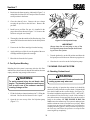
3. Install a new pre-filter. Be sure it is installed in the
proper direction as shown in Figure 7-4. Secure to the
fuel hose using the two clamps.
4. Thoroughly clean the outside of the filter housing. Dirt
must not be allowed to enter the fuel or the fuel injection
system.
Figure 7-5 Fuel Injection Pump
-IMPORTANTAlways keep the air vent plug on top of the
fuel injection pump closed except when bleeding air from the system.
5. Unscrew the fuel filter cartridge from the housing.
6. Apply a thin layer of fuel oil over the gasket of the new
cartridge and hand tighten the cartridge.
3. Turn the ignition key to the ON position and allow the
fuel pump to run for about one minute to purge the air.
7. Bleed the air from the fuel system.
4. Close the air vent valve on the fuel injection pump.
C. Fuel System Bleeding
7.6 ENGINE COOLANT SYSTEM
Bleeding the fuel system is necessary after the fuel filter
and lines have been removed, after the fuel tank has become
empty, and after long storage of the mower.
A. Checking Coolant Level
WARNING:
WARNING:
Hot coolant can scald. Check and service the
cooling system only when cool.
To avoid personal injury do not bleed a hot
engine. The bleeding procedure could cause
fuel to spill onto a hot exhaust manifold
creating a danger of fire.
Before each day of operation the coolant level should be
checked. Visually check the overflow bottle. Coolant should
be to the full mark on the overflow bottle. See Figure 7-6.
If coolant is within the range between “FULL “ and “LOW”,
the coolant will last for one day’s work. If the coolant is
low, add a mixture of water and anti-freeze to the overflow
bottle or the radiator. IF THE ENGINE IS HOT, DO
NOT remove the radiator cap. The system is under pressure
and the coolant can cause severe burns or eye injury. When
it is necessary to remove the radiator cap, wear protective
clothing and safety glasses. Always turn the cap slowly to
the first stop, and allow the pressure to escape before
removing the cap completely.
1. Fill the fuel tank per instructionsinsection 7.5, filling the
fuel tank. Be sure the fuel shut-off valve is open.
2. Open the air vent on top of the fuel injection pump
(Figure 7-5).
31
Section 7
-IMPORTANTDo not fill the radiator with coolant over the
“FULL” level of the overflow bottle. When coolant is added, the coolant level drops the first
time the engine is started. Stop the engine,
and add more coolant.
Debris Screen
Figure 7-7 Debris Screen Removal
-IMPORTANTTo prevent personal injury, always wear safety
glasses when using compressed air.
3. Clean the debris screen with compressed air or with a
water hose.
Figure 7-6 Coolant Overflow Bottle /Air Cleaner Cup
-NOTECheck the radiator for excessive debris and
clean with compressed air, if necessary.
B. Cleaning Radiator Debris Screen
After every 8 hours of operation, or daily, remove and clean
the radiator debris screen.
-IMPORTANTWhen operating the mower, occasionally look
at the engine water temperature gauge. If the
needle is in the red zone, stop the mower engine and remove and clean the debris screen.
4. Align the debris screen into the slots on the radiator
and carefully push the screen down until it bottoms
out.
C. Replacing Coolant
WARNING:
1. Open the engine hood.
2. Pull the radiator debris screen up to remove (Figure
7-7).
Change coolant only after the cooling system
has cooled. Possible scalding or eye injury
could occur.
The engine coolant should be replaced after every 500 hours
of operation or annually, whichever occurs first.
32
Section 7
1. Loosen the radiator cap, and open the radiator drain
valve. Open the engine block drain valve located on
the crankcase side of the engine. Drain the coolant
into a suitable container. Drain and clean the overflow
bottle.
CAUTION:
element and remove the element (Figure 7-8).
2. Close both drain valves securely.
3. Fill the radiator and cooling system with a mixture of
clean water and ethylene glycol based anti-freeze
(capacity of system - approx. 3 quarts). Mix the antifreeze for your coldest ambient temperature following
the manufacturer's instructions.
Wing Nut
4. If you add coolant more than once a month, or add
more than one quart at a time, have a Scag dealer
check the cooling system.
Air Filter Element
7.7 ENGINE AIR CLEANER
Air Cleaner Dust Cup
A. Emptying Air Cleaner Dust Cup
Wing Nut
After every 8 hours or daily, empty the air cleaner dust
cup. Squeeze the dust cup (Figure 7-8) to remove large
particles of dust and dirt.
To prevent personal injury, always wear safety
glasses when using compressed air.
Figure 7-8 Air Cleaner
B. Cleaning and/or Replacing Air Cleaner
Element
3. When dust adheres to the element, clean the
For any air cleaner, the operating environment dictates the
air cleaner service periods. Inspect and clean the air cleaner
element after every 100 hours of operation or bi-weekly,
whichever occurs first and replace the element if required.
filter element with compressed air. Use compressed
air pressure of not more than 99 psi to clean the element.
Rotate the element while directing the stream of air to
the inside of the element.
-NOTEIn extremely dusty conditions it may be necessary to check the element once or twice
daily to inhibit engine damage.
4. When carbon or oil adheres to the element, soak the
element in detergent for 30 minutes, then wash several
times in water, rinse with clean water and allow to air
dry. After the element has fully dried, inspect the inside
of element with a light and check for damage. (Refer
1. Remove the cover wing nut and remove the cover from
the air cleaner.
2. Remove the wing nut securing filter the air cleaner
33
Section 7
to instructions on the label attached to the element).
5. Replace the element after six cleanings or after every
500 hours of operation or annually, whichever occurs
first.
7.8 BATTERY
INTERNAL — Drink large quantities of water.
Follow with Milk Of Magnesia, beaten egg,
or vegetable oil. Get medical attention
immediately. In case of internal contact, DO
NOT give fluids that would induce vomiting.
1. Remove the battery cover by removing the two nuts
under the battery box.
A. Checking Electrolyte Level and Cleaning
Battery
2. Remove the battery cell caps. Visually inspect
electrolyte level in the cells. If electrolyte is
below the bottom of vent well, fill with clean distilled
water to the bottom of vent wells (1/4 to
1/2 inch above the plates). Install the battery cell caps.
WARNING:
After every 40 hours of operation or weekly, whichever
occurs first, check the electrolyte level in the battery and
clean the battery and connections. Dirt and fluid on the top
of the battery can cause the battery to discharge. Corrosion
of the battery terminals or loose connections will cause
poor battery performance.
-IMPORTANTDo not overfill the battery. Electrolyte will overflow through the vent tube onto parts of the
machine resulting in severe corrosion.
3. Clean the cable ends and battery posts with steel wool.
Use a solution of baking soda and water to clean the
battery. Do not allow the solution to enter the battery
cells.
WARNING:
Lead-acid batteries produce flammable and
explosive gases. To avoid personal injury when
checking, testing or charging batteries, DO
NOT use smoking materials near batteries,
keep arcs, sparks and flames away from
batteries, provide proper ventilation and wear
safety glasses.
4. Tighten the cable connections securely and apply a
light coat of silicone dielectric grease to the terminal
connections to prevent corrosion. Keep cable end
covers in place.
5. Install the battery cover.
B. Charging the Battery
Electric storage battery fluid contains sulfuric
acid which is POISON and can cause SEVERE
CHEMICAL BURNS. Avoid contact of fluid
with eyes, skin, or clothing. Use proper
protective gear when handling batteries. DO
NOT tip any battery beyond 45° angle in any
direction. If fluid contact does occur, follow
first aid suggestions below.
Refer to the battery charger’s manual for specific
instructions.
Under normal conditions the engine’s alternator will have
no problem keeping a charge on the battery. The only
condition in which the battery may cause a problem is when
it has been completely discharged for a long period of time.
Under this condition, the alternator may not be able to
recharge the battery, and a battery charger will be required
for charging the battery.
BATTERY ELECTROLYTE FIRST AID
EXTERNAL CONTACT — Flush with water.
Before using a battery charger, an attempt should be made
EYES — Flush with water for at least 15
minutes and get medical attention immediately.
34
Section 7
to recharge the battery using the engine alternator by first
jump starting the mower and letting the engine run. See
Jump Starting Instructions.
2. The booster battery must be a 12 volt type. If a vehicle
is used for jump starting, it must have a negative ground
system.
DO NOT charge a frozen battery, it may explode and cause
injury. Let the battery warm before attaching a charger.
3. When connecting the jumper cables, be sure the positive
is connected to the positive and the negative to the
negative.
Whenever possible, remove the battery from the mower
before charging and make sure the electrolyte covers the
plates in all cells.
4. After the engine starts, remove the black cable first,
then the red. Connect the field connection to the
alternator.
WARNING:
7.9 ENGINE DRIVE BELTS
BATTERIES PRODUCE EXPLOSIVE GASES.
Charge the battery in a well ventilated space
so gases produced while charging can
dissipate.
A. Checking Belt Tension and Damage
After the first 2, 4, and 8 hours of operation check for proper
tension on all engine belts and check for any damage.
Thereafter, check the belt tension after every 100 hours of
operation or bi-monthly, whichever occurs first.
Charging rates between 3 and 50 amperes are satisfactory
if excessive gassing or spewing of electrolyte does not occur
or the battery does not feel excessively hot (over 125°F).
If spewing or gassing occurs or the temperature exceeds
125°F, the charging rate must be reduced or temporarily
stopped to permit cooling.
C. Jump Starting
1. Using a belt tension gauge attached to the belt at the
position shown in Figure 7-10, check that the belt
deflects the distance shown with the proper tension
applied. Adjust the belt tension as necessary. See
Adjustment Section 6.
1. Disconnect the field connection from the alternator.
See Figure 7-9.
2. Check the belts for cracks, tears, and excessive wear.
Replace any damaged belt immediately.
7.10 CUTTER DECK BELTS
A. Checking Belt Tension and Damage
After the first 2, 4, and 8 hours of operation, check the
tension on the cutter deck drive belts and check for any
damage. Thereafter, chcck the belt tension after every 100
hours of operation or bi-monthly, whichever occurs first.
Remove Field
Connection From
Alternator
1. Using a belt tension gauge attached to the belt at the
position shown in figure 7-11, check that the belt deflects
1/2 inch with 10 pounds of force applied to the belt.
Adjust the belt tension as necessary. See Adjustment
Section 6.
Figure 7-9 Field Connection
2. Check the belts for cracks, tears, and excessive wear.
Replace any damaged belt immediately.
35
Section 7
Idler Pulley
Fan Pulley
Idler Pulley
Clutch Belt
Check
Tension
Here
Check
Tension
Here
Deflect 1/2" With
10 Pounds of
Pressure
Deflect 1/2" With
10 Pounds of Pressure
Fan Belt
Engine Pulley
Engine Pulley
Clutch Pulley
Check
Tension
Here
Alternator
Pulley
Fan Pulley
Pump Pulley
Engine Pulley
Alternator Belt
Deflect 1/2" With
10 Pounds of
Pressure
Deflect 0.28" to
0.38" With
22 Pounds of
Pressure
Check
Tension
Here
Pump Belt
Idler Pulley
Engine Pulley
Figure 7-10 Engine Belt Tension
Idler
Pulley
Check
Tension
Here
Gearbox
Pulley
Gearbox
Pulley
Idler
Pulley
Blade
Pulley
Mag-61 Belts
Check
Tension
Here
Check
Tension
Here
Blade
Pulley
Idler
Pulley
Blade
Pulley
Blade
Pulley
Mag-72 Belts
Blade
Pulley
Idler
Pulley
Figure 7-11 Cutter Deck Belt Tension
36
Blade
Pulley
Section 7
7.11 CUTTER BLADES
5. If a blade cutting edge is dull or nicked, it should be
sharpened. Remove the blades for sharpening. See
“Blade Replacement”.
A. Blade Inspection
-NOTEKeep the blades sharp. Cutting with dull blades
not only yields a poor mowing job, but slows
the cutting speed of the mower and causes
extra wear on the engine and the blade drive
by pulling hard.
Check the mower blades for straightness, sharpness and
the condition of cutting edge every 8 hours of operation, or
daily (or more often when mowing abrasive type grass or
operating on sandy soils). Blades will need to be replaced
if worn, bent, cracked or otherwise damaged as described
by blade replacement instructions in this section. The
following procedure should be used to check and sharpen
blades:
B. Sharpening Blades
-NOTEIf possible, use a file to sharpen the blade.
Using a wheel grinder may burn the blade.
1. Remove the ignition key before servicing the blades.
2. Use the mower deck height switch on the instrument
panel to raise the deck to its highest point.
-NOTEDO NOT sharpen the blades beyond 1/3 of
the width of the blade.
3. Use the mower deck lift switch to tilt the deck up as far
up as it will go.
Angle Blade Back
2. The booster battery must be a 12 volt type. If a vehicle
is used for jump starting, it must have a negative ground
system.
Do Not Cut In
3. When connecting the jumper cables, be sure the positive
is connected to the positive and the negative to the
negative.
30°
X Must NOT Exceed
1/3 Blade Width
Figure 7-12 Blade Sharpening
WARNING:
Never operate the cutter blades with
the deck in a raised position because
it is hazardous
1. Sharpen the cutting edge at same bevel as original.
See Figure 7-12. Sharpen only the top of the cutting
edge to maintain sharpness.
4. Check the blades for straightness by marking the tip
position of the blade on the inside of the deck. Then
rotate to the opposite tip of the blade to the same
position. cCompare the difference in blade tip track. If
the track is more than 1/8 inch, the blade is bent and
should be replaced.
2. Check the balance of the blade. If the blades are out
of balance, vibration and premature wear can occur.
See your authorized Scag dealer for blade balancing or
special tools, if you choose to balance your own blades.
C. Blade Replacement
WARNING:
1. Remove the ignition key before replacing the blades.
Do not attempt to straighten a bent blade, and
never weld a broken or cracked blade. Always
replace it with a new blade to assure safety.
2. Use the mower deck height switch on the instrument
37
Section 7
3. Use mower deck lift switch to tilt the deck up as far as
it will go.
4. Holding the nut at the top of the blade drive pulley with
a wrench, loosen and remove the blade attachment
bolt from beneath the mower deck. Remove the
washer, blade, and top and bottom cutter blade spacers.
Be sure not to misplace any of the blade spacers.
Spacers are important to align the blades to cut evenly.
4. Install the top and bottom blade spacers, blade, washer
and the blade attachment bolt to the bottom side of the
spindle. Install the locknut to the bolt and tighten to a
torque of 75 ft-lb. The nut and bolt must be tight to
inhibit wobble in the blade, causing vibration and poor
cutting.
7.13 BODY, DECK AND UPHOLSTERY
CAUTION:
Do not wash any portion pf the equipment
while it is hot. Do not wash the engine or
radiator, use compressed air.
1. After each use, wash the mower and deck. Use cold
water and automotive cleaners. Do not use pressure
cleaners.
2. Remove all cutter deck belt guards and clean debris
from the cutter deck.
7.12 TIRES
3. Do not spray water on electrical components.
Check tire pressures after every 8 hours of operation
or daily.
Caster Wheels ................................. 25 PSI
4. Use a mild soap solution or a vinyl/rubber cleaner to
clean the seat.
5. Repair damaged metal surfaces and use Scag touchup paint available from your authorized Scag dealer.
Wax and polish the mower for maximum paint
protection.
Rear Steering Wheel ........................ 15 PSI
Drive Wheels.........................................15 PSI
38
ILLUSTRATED PARTS LIST
MAGNUM III
39
MAG-61, MAG-72 CUTTER DECK
3
1
2
1
2
3
4
1
4
5
3
2
38
4
74
28
7
12
16
25
71
70
11
10
26
20
10
14
9
19
29
68
25
13
24
22
67
73
13
15
24
24
69
12
72
23
32
5
8
9
39
74
35
16
17
18
27
65
21
31
16
33
35
37
24
68
34
6
64
36
41
32
24
40
58
53
12
2
42
16
12
54
64
16
43
44
41
62
55
32
63
53
61
56
60
53
41
58
2
57
45
59
54
54
58
47
2
46
48
49
55
44
55
50
56
56
41
51
52
390S0111
40
MAG-61, MAG-72 CUTTER DECK
Ref. Part.
No. Number Description
1
2
3
4
5
6
7
8
9
10
11
12
13
14
15
16
17
18
19
20
21
22
23
24
25
26
27
28
29
30
31
32
33
34
35
36
37
38
39
04020-09
43278
04001-01
48926
48924
48753
48924
48923
04050-05
48100-02
48114-04
46866
04021-09
04041-12
43277
48269
04041-07
04001-54
45720
44107
43077
04001-46
45037
04041-08
04041-08S
04019-03
48100-05
46081
04001-19
04050-02
43028
44078
45816
45818
45815
45817
04029-03
481214
481213
04063-01
04001-109
48141
48265
481295
48204
48089
Mag Mag
61
72
Nut, Hex, 5/8-11
Spacer, Cutter Blade
Bolt, Hex Head, 1/4-20 x 3/4 Gr.5
Taper Hub, 1.125 Bore
Pulley, 5.75 Dia.
Pulley, 6.35 Dia.
Pulley, 5.75 Dia.
Pulley, 5.75 Double Groove
Retaining Ring, .75 Ext "E"
Bushing, Oilite - 1.125 ID
Grease Fitting
Arm, Idler (Includes 9 & 10)
Locknut, Elastic Stop, 3/8-16
Flat Washer, 3/8 (.375 x 1.50 x .060)
Spacer, J-Hook
Pulley, Idler
Flatwasher, 3/8 (.391 x .938 x .105)
Bolt, Hex Head, 3/8-16 x 3
Pivot, Idler Arm
J-Hook
Spacer, J-Hook
Bolt, Hex Head, 3/8-16 x 2-1/4
Idler Pivot
Flatwasher, 3/4 (.776 x 1.25 x .059)
Flatwasher, 3/4 (.776 x 1.25 x .035)
Serr. Fl. Hex Nut, 5/16-18
Bushing, Oilite - 3/4 ID
Idler Arm (Includes 10 & 25)
Bolt, Hex Head, 3/8-16 x 1
Retaining Ring, .75 Ext "E"
Pull Rod, Idler
Pull Rod, Idler
Belt Cover, RH
Belt Cover, RH
Belt Cover, LH
Belt Cover, LH
Wingnut, Plastic, 3/8-16
Gearbox, Deck Drive
Drive Shaft
Key, 1/4 x 1/4 x 1-1/4
Bolt, Hex Head, 1/4-20 x 1-3/8
(Full Thread)
Tapered Hub, 1.00 Bore
Belt, Cutter Deck
Belt, Cutter Deck
Belt, Cutter Deck
Belt, Cutter Deck
X
X
X
X
X
X
X
X
X
X
X
X
X
X
X
X
X
X
X
X
X
X
X
X
X
X
X
X
X
X
40
X
X
X
X
X
X
X
X
X
X
X
X
X
X
X
X
X
X
X
X
X
X
X
X
X
X
X
X
X
X
X
X
X
X
X
55
56
57
58
59
60
61
62
63
64
46867
46868
46631
43298
481024
481022
48114-04
48677
43294
43312
43296
481025
43297
481035
04063-08
481159
481160
04040-10
04001-41
48038
04001-10
04001-08
04030-03
04040-15
45046
421820
04017-16
65
66
67
68
69
70
71
72
73
74
04030-04
04001-19
04001-09
04021-10
481050
46726
04001-108
48181
04012-06
48098
41
42
43
44
45
46
47
48
49
50
51
52
53
54
X
X
X
X
X
Ref. Part
No. Number Descripton
X
X
X
X
X
Mag Mag
61
72
Cutter Deck with Decals
X
Cutter Deck with Decals
Spindle Assembly
X
Shaft, Cutter Spindle
X
Seal, 2.00 OD x 1.50 Bore
X
Bearing Assembly
X
Grease Fitting
X
Relief Fitting, Cutter Spindle
X
Spindle Housing
X
Spacer, Outside
X
Spacer, Inside
X
Seal, 2.00 OD x 1.625 OD
X
Spindle Bushing, Bottom
X
Nut, 1-1/16-18 UNEF-2B
X
Key, 1/4 x 1/4 x 2
X
Blade, 21"
X
Blade, 24-1/2"
Washer, 5/8 (.688 x 1.75 x .134)
X
Bolt, Hex Head, 5/8-11x 9-1/2 Gr.5 X
Roller
X
Bolt, Hex Head, 5/16-18 x 1-1/4
X
Bolt, Hex Head, 5/16-18 x 3/4
X
Lockwasher, 5/16
X
Flatwasher, 5/16 (.375 x .875 x .083) X
Shaft, Roller
X
Cover, Belt - Front
X
Serr. Fl Hex Head Capscrew,
5/16-18 x 3/4
X
Lockwasher, 3/8
X
Bolt, Hex Head, 3/8-16 x 1 Gr.5
X
Bolt, Hex Head, 5/16-18 x 1.0
X
Hex Locknut, Elastic Stop, 5/16-18 X
Spring, Discharge Chute
X
Discharge Chute
X
Bolt, Hex Head, 5/16-18 x 4-1/4
X
Pulley, Idler
X
Set Screw, Hex Socket, 3/8-16 x 1/2 X
Spindle Shield
X
X
X
X
X
X
-NOTESome of the hardware is common hardware and you may purchase it locally. Be sure that all bolts
purchased locally are a grade 5.
41
X
X
X
X
X
X
X
X
X
X
X
X
X
X
X
X
X
X
X
X
X
X
X
X
X
X
X
X
X
X
X
X
X
X
X
MAG-61, MAG-72 DECK SUPPORT
69
36
67
2
1
70
68
33
65
65
64
67
57
4
2
66
5
59
3
58
57
47
46
47
48
48
45
49
62
43
44 13
41
8
42
39
47
51
60
50
49
63
67
52
43
61
44
54
52
67
39
74
23
37
39
48
47
49
44
5
41
46
23
42
41
55
61
7
56
15
5
16
11
12
14
11
3
26
71
9
10
13
38
38
25
35
12
11
23
11
23
10
12
17
18
8
24
13
21
19
20
21
12
22
75
73
26
36
6
8
23 56
53
5
22
43
42
40
45 23
72
23
39
17
34
12
27
29
12
32
28
31
30 29 27
390S0112
42
MAG-61, MAG-72 CUTTER DECK SUPPORT
Ref. Part
No. Number Description
1
2
3
4
5
6
7
8
9
10
11
12
13
14
15
16
17
45733
04029-03
04001-52
481195
04019-06
04050-05
43356
04050-08
45728
421878
04001-117
04019-05
04063-19
481215
421838
04001-119
04017-16
18
19
20
422027
04020-21
46865
21
22
23
24
25
26
27
28
48100-06
04019-03
48114-04
45727
45722
45724
45723
45725
48100-08
43041
48537
29
30
31
32
33
34
35
36
37
48006-07
48006-06
48537-03
48537-02
04012-04
43022
04001-80
04021-07
46869
Mag Mag
61
72
Cover, Belt
X
Wingnut, Plastic, 3/8-16
X
Bolt, Hex Head, 1/2-13 x 2-1/2
X
Actuator, Deck Lift
X
Serr. Fl. Hex Nut, 1/2-13
X
Retaining Ring, 1.125 Ext
X
Pin, Deck support Mounting
X
Retaining Ring, 1.00 Ext "E"
X
Lift Bellcrank, LH Rear
X
Link, Deck Support
X
Bolt, Hex Head, 7/16-14 x 1-3/4
X
Serr. Fl. Hex Nut, 7/16-14
X
Key, 1/4 x 1/4 x 3/4
X
Spring, Deck Lift
X
Anchor, Deck Spring
X
Bolt, Hex Head, 5/8-11 x 5-1/2
X
Serr. Fl. Hex Head CPSCR,
5/16-18 x 3/4
X
Retainer, Spring
X
Hex Nut, 3/4-16
X
Push Rod Assy (Includes 19, 21, 23,
53)
X
Bushing, Olite - 3/4 ID
X
Serr. Fl. Hex Nut, 5/16-18
X
Grease Fitting
X
Lift Bellcrank, Front
X
Tube, LH Caster (Shown)
X
Tube, LH Caster (Shown)
Tube, RH Caster (Not Shown)
X
Tube, RH Caster (Not Shown)
Bushing, Olite - 1.00 ID
X
Spacer
X
Wheel Assembly, Caster (includes
29, 30, 31, 32)
X
Retainer
X
Bearing, Roller
X
Rim
X
Tire
X
Setscrew, Hex Socket, 5/16-18 x .75 X
Sleeve, Caster Wheel
X
Bolt, Hex Head, 1/2-13 x 6-1/2
X
Hex Locknut, Elastic Stop, 1/2-13
X
Frame, Deck Support (Includes 23,
38,39, 74)
X
X
X
X
X
X
X
X
X
X
X
X
X
X
X
X
X
X
X
X
X
X
X
X
X
X
X
X
X
X
X
X
X
X
X
X
X
X
Ref. Part
No. Number Description
38
39
40
41
42
43
44
45
46
47
48
49
50
51
52
48100-02
48100-08
04021-13
04042-05
04041-14
43353
04001-45
04021-09
04020-09
43270
04040-09
04050-01
45731
43271
04064-11
04044-01
53
54
55
56
57
58
59
60
61
62
63
64
65
66
67
68
69
70
71
72
73
74
75
481217
04001-120
04021-14
43352
04020-04
43357
44113
04004-15
04063-01
45729
04062-01
481216
421834
04001-118
04040-07
45730
04001-72
04020-07
45325
04066-01
45332
481331
481379
Mag Mag
61
72
Bushing, Olite - 1-1/8 ID
Bushing, Olite - 1.00 ID
Hex Locknut, Elastic Stop, 5/8-11
Flatwasher, 1" (1.062 x 1.75 x .10)
Flatwasher, 1" (1.062 x 1.50 x .048)
Spacer
Bolt, Hex Head, 3/8-16 x 2
Hex Locknut, Elastic Stop, 3/8-16
Hex Nut, 5/8-11
Swivel Joint, RH
Flatwasher, 5/8 (.656 x 1.312 x .095)
Retaining Ring, 5/8 Ext "E"
Lever, Deck Lift
Swivel Joint, LH
Pin, Clevis, 1/2 x 2.25
Flatwasher, Nylon, 1" (.54 x 1.125
x 25)
Rod End, Male, 3/4-16 RH
Bolt, Hex Head, 3/4-16 x 3
Hex Locknut, Elastic Stop, 3/4-16
Spacer
Hex Nut, 3/8-16
Swivel Joint, LH
Rod, Height Indicator
Stud, Mower Lift
Key, 1/4 x 1/4 x 1-1/4
Lift, Bellcrank, RH Rear
Cotter Pin, Hair - 0.94 x 1.62
Actuator, Cutting Height
Link, Deck Travel Limit
Bolt, Hex Head, 1/2-13 x 4-3/4
Flatwasher, 1/2 (.531 x 1.06 x .095)
Lever, Bellcrank Actuation
Bolt, Hex Head, 1/2-13 x 2
Hex Nut, 1/2-13
Yoke, Caster Wheel
Quick Pin
Shaft, Push Rod
Decal, Cutting Height
Cover, Spring
X
X
X
X
X
X
X
X
X
X
X
X
X
X
X
X
X
X
X
X
X
X
X
X
X
X
X
X
X
X
X
X
X
X
X
X
X
X
X
X
X
X
X
X
X
X
X
X
X
X
X
X
X
X
X
X
X
X
X
X
X
X
X
X
X
X
X
X
X
X
X
X
X
X
X
X
X
X
X
-NOTESome of the hardware is common hardware and you may purchase it locally. Be sure that all bolts
purchased locally are a grade 5.
43
RIDER FRAME
60
61
6
8
1
7
2
38
54
9
49
50
4
48
3
51
53
5
10
52
57
4
46
41
46
11
48
45
58
44
47
10
46
59
13
12
43
42
15
14
55
36
35
17
16
18
56
3
33
37
41
18
34
38
19
40
32
20
31
39
30
29
16
28
27
22
26
25
24
23
21
390S0113
44
RIDER FRAME
Ref. Part
No. Number Description
Ref. Part
No. Number Description
1
2
3
4
5
6
7
8
9
10
11
12
13
14
15
16
17
18
19
20
21
22
23
24
25
26
27
28
29
30
31
32
33
34
35
36
37
38
39
40
41
42
43
44
45
46
47
48
49
50
51
52
53
54
55
56
57
58
59
60
61
46029
48159
04021-10
04040-15
04001-12
481156
421976
04003-11
04050-05
48100-02
46870
04001-83
45606
481056
45698
481154
43329
04020-12
45794
04021-13
43020-05
481345
48005-06
48005-05
48005-04
48114-06
48005-03
481345-02
43398
43020-06
04001-91
04001-115
481476
Handle, Steering (Includes 2)
Handle Grip
Hex Locknut, Elastic Stop, 5/16-18
Flatwasher, 5/16 (.375 x .875 x .083)
Bolt, Hex Head, 5/16-18 x 1.75
Seat (with Adjuster Rails)
Plate, Seat Mount
Carriage Bolt, 3/8-16 x 1-1/4
Retaining Ring - 1.125 Ext
Bushing, Oilite - 1-1/8 ID
Frame, Steering
Bolt, Hex Head, 7/16-14 x 3-1/2
Pedal, Foot Interlock
Spring, Foot Interlock Switch
Pivot, Rear Yoke
Connector Link, #50 Chain
Anchor Bolt, Chain
Nut, Jam, 3/8-16
Yoke, Rear
Hex Locknut, Elastic Stop, 5/8-11
Spacer, Rear Wheel
Rear Wheel Assembly (Includes 23-29)
Seal, Grease
Bearing Cone
Bearing Cup
Grease Fitting
Rim (Includes 23, 24, 25 & 26)
Tire
Sleeve, Rear Tire
Spacer, Rear Wheel
Bolt, Hex Head, 7/16-14 x 2-1/2
Bolt, Hex Head, 5/8-11 x 11-1/4
Switch, Foot Interlock
04021-08
04017-17
04010-17
45699
04019-03
481152
45696
48100-01
04003-18
421784
04019-06
45502
48114-04
46880
48100-06
45506
04065-01
04019-04
42366
42026
04021-11
04003-12
421988
04050-03
421755
421757
481480
481158
Hex Locknut, Elastic Stop, 1/4-20
Serr. Fl. Hex Head Capscrew, 5/16-18 x 1.00
Screw, Flat Hed, #10-32 x 3/4
Footplate, LH
Serr. Fl. Hex Nut, 5/16-18
Chain, Steering - #50
Shaft, Steering
Bushing, Bronze - .877 ID
Carriage Bolt, 1/2-13 x 1-3/4
Pad, Reinforcement
Serr. Fl. Hex Nut, 1/2-13
Foot Pedal
Grease Fitting
Footplate, RH
Bushing, Oilite - 3/4 ID
Foot Pedal Arm
Pin, Drive Lock, 3/16 x 1-1/4
Serr. Fl. Hex Nut, 3/8-16
Reinforcement, Spring
Spring, Seat Support
Hex Locknut, Elastic Stop, 7/16-14
Carriage Bolt, 5/16-18 x 3/4
Retainer, Bolt
Retaining Ring, 7/8 Ext
Guide, Top Chain
Divider, Chain Spacer
Armrest Assembly
Track Set, Seat
-NOTESome of the hardware is common hardware and you may purchase it locally. Be sure that all bolts
purchased are a grade 5.
45
ENGINE DECK
1
37
2
53
17
56
3
52
4
17
56
5
7
57
17
51
18
37
50
47
6
46
67
48
11
8
16
38 10
44
15
61
60
A
59 65
64
49
14
58
9
17
45
61
12
63
64
B
68
B
65
70
62
66
13
54
14
17
18
14
58
43
63
19
20
69
51
A
39
71
42
29
37
41
35
40
21
14
15
17
16
24
27
28
37
25
26
36
55
19
34
33
32
30
22
31
23
390S0114
46
ENGINE DECK
Ref. Part
No. Number Description
Ref. Part
No. Number Description
1
2
3
4
5
6
7
8
9
10
11
12
13
14
15
16
17
18
19
20
21
22
23
24
25
26
27
28
29
30
422002
04010-01
481309
04020-01
421801
*
422236
421802
04030-05
04002-10
04021-11
04020-07
04030-06
04019-06
04017-38
421782
04019-03
421806
04001-52
04017-16
422027
48680
04028-01
481205
481205-02
481205-03
46825
04008-01
04040-15
48461
31
32
33
34
35
48461-02
48461-03
48461-05
48461-04
48769
36
37
38
39
40
41
42
43
44
45
46
47
48
49
50
51
52
53
54
55
56
57
58
59
60
61
62
63
64
65
66
67
68
69
70
71
Catch, Hood Latch
Screw, Round Head Washer, #10-32 x 1/2
Latch, Hood
Hex Nut, #10-32
Stiffener, Hood
Engine, Kubota, 28 HP Diesel
Hood
Mounting Plate, Engine
Lockwasher, 7/16
Bolt, Hex Head, M10 - 1.25 x 25
Hex Locknut, Elastic Stop, 7/16-14
Hex Nut, 1/2-13
Lockwasher, 1/2
Serr. Fl. Hex Nut, 1/2-13
Serr. Fl. Hex Head Capscrew, 1/2-13 x 1-1/2
Stop, Cutter Deck
Serr. Fl. Hex Nut, 5/16-18
Anchor, Deck Spring
Bolt, Hex Head, 1/2-13 x 2-1/2
Serr. Fl. Hex Head Capscrew, 5/16-18 x 3/4
Retainer, Spring
Castle Nut, 1.0-20 UNEF
Nut, Wheel
Wheel Assembly (Includes 25, 26)
Tire, 23 x 1050 -12, 4-ply
Rim
Hub, Wheel (includes 28)
Bolt, Hub
Flat Washer, 5/16 (.375 x .875 x .083)
Parking Brake Assembly (Includes 31, 32,
33, 34)
Brake Pads - Pair
Springs - Pair
Clip
Actuating Arm
Motor, Hydraulic - White (Includes 22)
04001-28
04003-12
43394
48205
04021-10
421798
481177
421799
04003-20
421781
48711
481164
421288
04017-05
04021-08
04003-14
481165
421783
45862
04061-04
481284
04019-03
481440
481441
481442
48603-04
481443
481444
481445
481446-01
481447
481457
48572-08
422239
*
04001-01
Bolt, Hex Head, 7/16-14 x 1-1/4
Carriage Bolt, 5/16-18 x 3/4
Stud, Metric
Pad, Rubber
Nex Locknut, Elastic Stop, 5/16-18
Battery Box
Battery
Hold Down, Battery
Carriage Bolt, 5/16-18 x 10
Support Bracket, Hydraulic Tank
Hydraulic Tank
Cap, Hydraulic Tank
Strap, Hydraulic Tank
Serr. Fl. Hex Head Capscrew, 1/4-20 x 3/4
Hex Locknut, Elastic Stop, 1/4-20
Carriage Bolt, 5/16-18- 1/2
Hinge
Plate, Hinge
Engine Deck
Pin, Cotter, 5/32 x 1-1/2
Bumper, Rubber
Nut, 5/16-18 Serrated Flange
Adapter, Remote Oil Filter
Gasket, Oil Filter Adapter
MTG Bolt, Filter Adapter
O- Ring
Reducer, Remote Filter
Hose Assy., Remote Filter
Hose Assy., Remote Filter
Connector, 1/2 Pipe x 3/4 JIC
Nut, 7/8 - 14
Spring Filter Adapter
Tube Union, 7/8-14 JIC x O-Ring
Guard Oil Filter
Oil Filter, Engine
Bolt, 1/4-20 X .75 Hex Head
*Available through the engine manufacturer only.
-NOTESome of the hardware is common hardware and you may purchase it locally. Be sure that all bolts
purchased are a grade 5.
47
RADIATOR/OIL COOLER
29
4
1
27
2
31
3
7
2
6
5
28
30
8
9
11
10
24
23
26
23
25
24
11
20
16
2
19
18
13
14
12
15
16
17
21
22
390S0115
48
RADIATOR/OILCOOLER
Ref. Part
No. Number Description
1
2
3
4
5
6
7
8
9
10
11
12
13
14
15
16
17
18
19
20
21
22
23
24
25
26
27
28
29
30
31
481207
48136-06
45783
04019-03
*
422192
04003-12
481286
45784
45785
04001-06
422010
421992
04003-11
*
*
04021-05
*
481302
481206
04041-07
04021-09
04040-14
04030-02
48576-03
481383-01
422194
04001-44
04001-59
04019-02
04021-08
Hose, Upper Radiator
Clamp, Hose
Shroud, Fan
Serr. Fl. Hex Nut, 5/16-18
Tank, Coolant Overflow
Mounting Bracket, Coolant Tank
Carrage Bolt, 5/16-18 x .75
Radiator with Oil Cooler
Frame, Debris Screen
Screen. Debris
Bolt, Hex Head, 1/4-20 X 5/8
Side Rail, Debris Screen
Bracket, Radiator Mounting
Carriage Bolt, 3/8-16 x 1-1/4
Cushion, Radiator Mounting
Washer, Radiator Mounting
Locknut, 3/8-16
Cushion, Radiator Mounting
Drain Cock
Hose, Lower Radiator
Flatwasher, 3/8 (.391 x .938 x .105)
Hex Locknut, Elastic Stop, 3/8-16
Flatwasher, 1/4 (.312 X .75 X .065)
Lockwasher, 1/4
Coupling, 1/4 NPT
Nipple, 1/4 NPT x 2.0
Strap, Coolant Bottle
Bolt, Hex Head, 1/4-20 x .50
Bolt, Hex Head, 1/4-20 x 1.25
Serr. Fl. Hex Nut, 1/4-20
Hex Locknut, Elastic Stop, 1/4-20
* Available only through the engine manufacturer.
-NOTESome of the hardware is common hardware and you may purchase it locally. Be sure that all bolts
purchased are a grade 5.
49
MUFFLER AND AIR CLEANER
4
3
1
2
1
5
6
7
9
8
10
11
20
19
15
18
16
15
14
13
15
14
12
17
15
390S0116
50
MUFFLER AND AIR CLEANER
Ref. Part
No. Number Description
1
2
3
4
5
6
7
8
9
10
11
12
13
14
15
16
17
18
19
20
48136-08
481191
481333
04100-03
481192
421981
04030-03
04020-03
*
481340
04015-07
422029
04001-09
04003-12
04019-03
421983
481439
48633
422254
04011-08
Hose Clamp
Hose, Air Intake
Cap. Precleaner
U-Bolt
Air Cleaner
Mounting Bracket, Air Cleaner
Lockwasher, 5/16
Nut, Hex, 5/16-18
Gasket, Manifold
Adapter, Manifold
Capscrew, Socket Head, M8-1.125 x 20
Brace, Muffler Suport
Bolt, Hex Head, 5/16-18 x 1
Carriage Bolt, 5/16-18 x 3/4
Serr. Fl. Hex Nut, 5/16-18
Bracket, Muffler Support
Muffler
Clamp, Exhaust Pipe
Muffler Guard
Screw, 10-32 x .50 Type F HH
*Available only through the engine manufacturer.
-NOTESome of the hardware is common hardware and you may purchase it locally. Be sure that all bolts
purchased are a grade 5.
51
DECK DRIVE SYSTEM
31
27
28
23
18
19
20
37
36
51
25
22
35
21
23
30
34
27
28
33
44
49
29
26
46
38
50
9
32
45
50
17
47
41
42
5
46
48
24
16
39
4
24
3
15
43
40
2
14
8
11
1
13
12
10
9
8
7
6
390S0117
52
DECK DRIVE SYSTEM
Ref. Part
No. Number Description
Ref. Part
No. Number Description
1
2
3
4
5
6
7
8
9
10
11
12
13
14
15
16
17
18
19
20
21
22
23
24
25
26
27
28
29
30
31
32
33
34
35
36
37
38
39
40
41
42
43
44
45
46
47
48
49
50
51
04001-101
04030-05
481204
481104
46827
43321
481024
481022
48114-04
43294
48677
43296
43312
481025
43297
481112
04063-21
04002-13
43428
481469
04020-03
04040-15
04030-03
04019-03
45873
04001-46
Bolt, Hex Head, 7/16-20 x 2-1/2
Lockwasher, 7/16
Clutch, Electric
Belt, Deck Drive
Spindle, Deck Drive (Includes 6 thru 16)
Shaft, Deck Drive
Seal, 2.00 O.D. 1-1/2 Bore
Roller Bearing (Replace as a set only)
Grease Fitting
Housing, Spindle
Relief Fitting
Spacer, Outside
Spacer, Inside
Seal, 2.00 O.D. x 1-5/8 Bore
Spindle Bushing, Bottom
Nut, 1-1/16-18
Key, #807 Woodruff, 1/4 x 7/8
Bolt, Hex Head, M8-1.25 x 40
Base, Anti-Rotation-Clutch
Isolator, Rubber
Nut, Hex, 5/16-18
Flatwasher, 5/16 (.375 x .875 x .083)
Lockwasher, 5/16
Serr. Fl. Hex Nut, 5/16 - 18
Anchor Bracket, J-Bolt
Bolt, Hex Head, 3/8-16 x 2-1/4
04021-09
04041-07
48181
43028
43336
46871
45212
04017-16
43330
04001-10
04017-19
45792
422018
45712
04017-27
04003-12
04019-06
43282
04050-02
04019-03
04003-19
04021-07
04041-11
48100-05
04019-05
Hex Locknut, Elastic Stop, 3/8-16
Flatwasher, 3/8 (.391 x .938 x .105)
Pulley, Idler
Rod, J-Hook
Spacer
Idler Arm, Clutch
Bracket, Idler Pivot
Serr. Fl. Hex Head Capscrew, 5/16-18 x 3/4
Hub, Brake
Bolt, Hex Head, 5/16-18 x 1-1/4
Serr. Fl. Hex Head Capscrew, 5/16-18 x 1-1/2
Belt Guard, Electric Clutch
Brace, Fan Support - LH
Upright, Fan Support - LH
Serr. Fl. Hex Head Capscrew, 3/8-16 x 1
Carriage Bolt, 5/16-18 x 3/4
Serr. Fl. Hex Nut, 1/2-13
Spacer, J Pull Rod
Retaining Ring, .75 Ext
Serr. Fl. Hex Nut, 5/16-18
Carriage Bolt, 1/2-13 x 1-1/4
Lock Nut, Elastic Stop, 1/2-13
Flat Washer, 3/8 ( .406 x 1.50 x .179)
Bushing, Oilite - .753 I.D.
Nut, 7/16-14 Serr. Flg.
-NOTESome of the hardware is common hardware and you may purchase it locally. Be sure that all bolts
purchased are a grade 5.
53
PUMP AND FAN DRIVE SYSTEMS
14
8
12
7
7
8
15
11
10
7
9
8
16
7
1
2
4
8
5
17
3
11
6
48
8
7
17
3
47
29
34
46
35
18
20
45
49
24
22
PART OF
ENGINE
23
36
13
21
25
50
4
37
38
49
28
39
7
19
27
8
26
31
7
8
32
30
33
40
44
21
42
7
43
41
10
390S0118
54
PUMP AND FAN DRIVE SYSTEMS
Ref. Part
No. Number Description
Ref. Part
No. Number
Description
1
2
3
4
5
6
7
8
9
10
11
12
13
14
15
16
17
18
19
20
21
22
23
24
25
26
27
28
29
30
31
32
33
34
35
36
37
38
39
40
41
42
43
44
45
46
47
48
49
50
Belt, Fan Drive
Upright, Fan Support - RH
Base, Idler Pivot - Pump
Rod, J-Hook
Spacer, J Pull Rod
Grease Fitting
Taper Hub, .75 Bore
Pulley, Pump, 5.94 O.D.
Bolt, Hex Head, 1/4-20 x 3/8
Belt, Pump Drive
Taper Hub, 1-7/16 Bore
CPSCR, Socket Head, 1/4-20 x 1-1/4
Retaining Ring, .75 Ext
Pulley, Idler, 5.95 O.D.
Bushing, Olite - .75 I.D.
Arm, Idler (Includes 33, 42)
Serr. Fl. Hex Nut, 5/16-18
Pulley, Double Groove
Key, 3/8 x 1-1/4
Stubshaft, Crankshaft
Spacer
Carriage Bolt, 5/16 - 18 x .75
Flatwasher, 1/4
04021-16
43335
48442
04003-19
46872
422017
04021-09
04041-07
04003-06
04001-32
04003-11
422019
04019-02
421808
04021-08
04003-12
04019-06
43334
04030-02
*
04001-21
481315
*
43390
04001-114
04001-116
481330
Hex Locknut, 1/2-20
Spacer, Fan
Bearing
Carriage Bolt, 1/2-13 x 1-1/4
Bracket, Fan Mounting (Includes 3, 48)
Idler Bracket, Fan Drive
Hex Locknut, Elastic Stop, 3/8-16
Flat Washer, 3/8 (.391 x .938 x .105)
Carriage Bolt, 1/4-20 x 1
Bolt, Hex Head, 3/8-16 x 1-1/4
Carriage Bolt, 3/8-16x 1-1/4
Brace, Fan Support
Serr. Fl. Hex Nut, 1/4-20
Guard, Pump Belt
Hex Locknut, Elastic Stop, 1/4-20
Carriage Bolt, 5/16-18 x 3/4
Serr. Fl. Hex Nut, 1/2-13
Hub, Fan
Lockwasher,1/4
Pulley, Fan
Bolt, Hex Head, 3/8-18x 1-3/4
Pulley, Belt Tensioning Idler
Fan
Hub, Fan
Bolt, Hex Head, 1/2-20 x 4.75 LH Thread
Bolt, Hex Head, 1/4-28 x 1
Pulley, 4.25 O.D. x 1.4375 I.D.
481114
45713
45307
44107
43282
48114-04
48761
48790
04001-109
481103
481168
04015-09
04050-02
48181
48100-05
46878
04019-03
481329
04063-22
*
43139
04003-12
04040-14
* Available only from the engine manufacturer.
-NOTESome of the hardware is common hardware and you may purchase it locally, Be sure that all bolts
purchased are a grade 5.
55
INSTRUMENT PANEL
4
3
2
1
29
27
6
7
31
30
9
33
8
28
9
10
12 11
12 11
5
21
20
12
11
9
19
12
9
13
11
14
15
25
20
21
20
19
32
16
16
20 26
21
29
9
12
25
18
24
11
18
17
15
19
20
21
22
23
390S0119
56
INSTRUMENT PANEL
Ref. Page
No. Number Description
1
2
3
4
5
6
7
8
9
10
11
12
13
14
15
16
17
18
19
20
21
22
23
24
25
26
27
28
29
30
31
32
33
34
35
36
48023
481183
481306
481184
46873
42413
04021-01
04010-11
04010-01
*
04031-01
04020-01
481182
*
04003-12
481087
46874
48100-06
04040-04
04030-03
04020-03
04019-03
48114-04
421788
48788
481311
422193
04001-59
04001-08
481181
481316
422004
04019-02
04021-19
04041-07
04001-32
Hourmeter
Gauge, Water Temperature
Gauge, Fuel Level
Voltmeter
Instrument Panel with Decal
Bracket, Fuse Holder
Hex Locknut, Elastic Stop, #10-32
Screw, Round Head, #10-32 x 1-1/2
Screw, Round Head, #10-32 x 1/2
Timer, Glow Plug
Lockwasher, External Tooth, #10
Hex Nut, #10-32
Indicator Light, Glow Plug, Yellow Lens
Keyswitch
Carriage Bolt, 5/16-18 x 3/4
Switch, Deck Lift
Mounting Bracket, Instrument Panel (Includes 18, 23)
Bushing, Oilite - .75 I.D.
Flatwasher, 5/16 (.281 x .625 x .065)
Lockwasher, 5/16
Hex Nut, 5/16-18
Serr. Fl. Hex Nut, 5/16-18
Grease Fitting
Guide, Clutch Lever
Relay, Synchronize Start and Cutter Blade
Rubber Isolator
Brace, Instrument Panel
Serr. Flg. Hex Head Capscrew, 5/6-18 x 3/4
Bolt, Hex Head, 5/16-18 x 3/4
Indicator Light, Oil Pressure, Red Lens
Timer, Delay Circuit
Bracket, Support Brace
Serr. Fl. Hex Nut, 5/16-18
Hex Nut, Elastic Stop, 3/8-16
Flatwasher, 3/8 (.391 x .938 x .105)
Bolt, Hex Head, 3/8-16 x 1-1/4
*Available only from the engine manufacturer.
-NOTESome of the hardware is common hardware and you may purchase it locally. Be sure that all bolts
purchased are a grade 5.
57
WIRING HARNESS AND ELECTRICAL COMPONENTS
1
28
29
8
2
7
31
9
6
5
30
4
10
3
11
11
27
18
26
25
32
24
12
33
13
34
23
2
22
15
15
16
17
18
21
19
20
14
390S0120
58
WIRING HARNESS AND ELECTRICAL COMPONENTS
Ref. Page
No. Number Description
1
2
3
4
5
6
7
8
9
10
11
12
13
14
15
16
17
18
19
20
21
22
23
24
25
26
27
28
29
30
31
32
33
34
481216
481185
481182
48023
481183
481306
481316
481322
*
481182
48788
*
481087
481476
481474
481304
04021-10
48030-10
04003-12
481204
*
481195
*
04025-02
481335
481190
481177
481336
481176-02
481337
481176-01
04025-01
04017-16
04019-03
Actuator, Cutting Height
Wire Harness
Indicator Light, Oil Pressure
Hourmeter
Gauge, Water Temperature
Gauge, Fuel Level
Timer, Delay Circuit
Fuse, 30 Amp
Timer, Glow Plug
Indicator Light, Glow Plug
Relay, Synchonize Start and Clutch Kill Circuit
Switch, Ignition
Switch, Deck Lift and Cutting Height
Switch, Safety - Parking Brake
Switch, Foot Pedal and Cutter Brake Interlocks
Sender, Fuel (includes Gasket and Screws)
Hex Locknut, Elastic Stop, 5/16-18
Clamp
Carriage Bolt, 5/16-18 x 3/4
Electric Clutch
Fuel Pump, Electric
Actuator, Deck Lift
Sender, Oil Pressure
Hex Nut, M8- 1.25
Cap, Alternator Terminal
Sender, Water Temperature
Battery
Cap, Battery Terminal - Black
Battery Cable, Black
Cap, Battery Terminal - Red
Battery Cable, Red
Hex Nut, M6 - 1.00
Serr. Fl.Hex Head Capscrew, 5/16-18 x3/4
Serr. Fl. Hex Nut, 5/16-18
* Available only from the engine manufacturer.
-NOTESome of the hardware is common hardware and you may purchase it locally. Be sure that all bolts
purchased are a grade 5.
59
CUTTER BRAKE LINKAGE
1
7
6
2
2
3
5
4
9
8
14
17
6
10
12
11
35
29
14
11
38
13
14
15
18
16
24
36
39
40
25
22 21
25
40
13
41
16
27
41
19
24
11
27
30
37
23
26
20
11
39
40 25
31
21
21
34
25
14
28
40
21
32
33
14
390S0121
60
CUTTER BRAKE LINKAGE
Ref. Part
No. Number Description
1
2
3
4
5
6
7
8
9
10
11
12
13
14
15
16
17
18
19
20
21
22
23
24
25
26
27
28
29
30
31
32
33
34
35
36
37
38
39
40
41
04041-08
04041-08S
04050-02
45702
04021-10
481163
04019-03
04017-17
04020-04
48092
481244
04041-07
04001-51
04017-26
04021-09
48464
04001-53
45693
04017-19
421805
481474
04019-04
04001-31
46875
48114-05
48100-04
44109
04062-02
46876
43212
04001-20
481034
04001-26
481170
43337
43336
44110
04017-20
04020-14
43110
04040-04
04021-10
Flatwasher, 3/4 (.766 x 1.250 x .060)
Flatwasher, 3/4 (.766 x 1.250 x .035)
Retaining Ring - .75 Ext
Lever, Clutch Engage
Hex Locknut, Elastic Stop, 5/16-18
Spring, Clutch Lever
Serr. Fl. Hex Nut, 5/16-18
Serr. Fl. Hex Head Capscrew, 5/16-18 x 1
Nut, Hex, 3/8-16
Grip, Clutch Lever
Spring, Friction Control
Flatwasher, 3/8 (.391 x .938 x .105)
Bolt, Hex Head, 3/8-16 x 3-3/4
Serr. Fl. Hex Head Capscrew, 3/8-16 x 3/4
Hex Locknut, Elastic Stop, 3/8-16
Ball Joint, RH Thd, 3/8-16
Bolt, Hex Head, 5/16-18x 2-1/2
Lever, Clutch
Serr. Fl. Hex Head Capscrew, 5/16-18 x 1-1/2
Base, Brake Assembly
Switch, Interlock
Serr. Fl. Hex Nut, 3/8-16
Bolt, Hex Head, 3/8-16 x 2-1/2
Lever, Brake Engage (Includes 24, 25)
Grease Fitting, Short
Bushing, Oilite - .50 I.D.
Rod, Clutch Engage
Cotter Pin, Hair (.080 x1.19)
Bellcrank, Clutch Engage (Includes 24, 25)
Sleeve
Bolt, Hex Head, 3/8-16 x 1-1/2
Spring, Brake
Bolt, Hex Head, 3/8-16 x 1-1/4
Brake Band
Anchor, Brake
Spacer, Brake
Rod, Clutch Engage
Serr. Fl. Hex Head Capscrew, 5/16-18 x 1-3/4
Hex Nut, 3/8-24
Sleeve, Control Lever
Flatwasher, 5/16 (.344 x .688 x .065)
Hex Locknut, Elastic Stop, 5/16-18
-NOTESome of the hardware is common hardware and you may purchase it locally. Be sure that all bolts
purchased are a grade 5.
61
PARKING BRAKE LINKAGE
1
28
27
6
2
17
16
29
3
16
8
4
18
14
6
30
20
15
5
16
14
11
23
6
21
34
24
6
13
22
6
5
19
12
10
8
35
9
3
16
31
7
4
32
8
6
7
24
21
26
20
25
20
12
22
23
24
62
MAG008
33
4
3
PARKING BRAKE LINKAGE
Ref. Part
No. Number Description
1
2
3
4
5
6
7
8
9
10
11
12
13
14
15
16
17
18
19
20
21
22
23
24
25
26
27
28
29
30
31
32
33
34
35
48093
45716
48114-04
04050-01
04020-05
04041-07
48464
04021-09
45782
04020-14
04004-23
04003-05
481474
04001-19
04017-17
04019-04
45781
04001-21
421338
04019-02
04001-59
44108
43032
0462-02
45705
04017-37
04019-03
04019-06
48544
43212
44124
45834
04001-51
45835
04003-03
Grip, Handle
Lever, Brake
Grease Fitting
Retaining Ring, .625 Ext
Hex Locknut, Elastic Stop, 3/8-16
Washer, Flat, 3/8 (.391 x .938 x .105)
Ball Joint, 3/8-24 RH Thd
Hex Locknut, Elastic Stop, 3/8-16
Arm, Weldment
Hex Nut, 3/8-24
Rod, Parking Brake
Carriage Bolt, 3/8-16 x 1-1/2
Switch, Interlock
Bolt, Hex Head, 3/8-16 x 1.00
Serr. Fl. Hex Head Capscrew, 5/16-18 x 1.00
Serr. Fl. Hex Nut, 3/8-16
Mounting Base, Parking Brake
Bolt, Hex head, 3/8-16 x 1-1/4
Link, Cam
Serr. Fl. Hex Nut, 1/4-20
Bolt, Hex Head, 1/4-20 x 1-1/4
Rod, Brake Actuator
Swivel
Hair Pin, Cotter, .08 x 1.19
Actuator, Brake
Serr. Fl Hex Head Capscrew, 1/2-13 x 1-3/4
Serr. Fl. Hex Nut, 5/16-18
Serr. Fl. Hex Nut, 1/2-13
Ball Joint, 3/8-24 LH Thread
Sleeve
Rod, Interlock
Bracket, Neutral Lockout Mounting
Bolt, Hex Head, 3/8-16 x 3.75
Bracket, Neutral Lockout
Carriage Bolt
-NOTESome of the hardware is common hardware and you may purchase it locally, Be sure that all bolts
purchased are a grade 5.
63
THROTTLE LINKAGE
1
2
32
3
15
34
23
28
28
9
37
10
7
26
27
7
35
5
6
8
30
11
29
4
12
38
30
17
13
18
27
33
26
18
17
25
31
23
16
14
19
39
36
20
23
21
19
24
21
22
390S0123
64
THROTTLE LINKAGE
Ref. Part
No. Number Description
1
2
3
4
5
6
7
8
9
10
11
12
13
14
15
16
17
18
19
20
21
22
23
24
25
26
27
28
29
30
31
32
33
34
35
36
37
38
39
04003-02
421776
04019-02
04001-13
46877
48114-05
48100-04
44115
04002-11
45822
04021-13
04041-10
481244
04004-26
04020-03
481189
04040-04
04001-10
04019-02
481314
04019-03
04001-39
04021-10
04001-59
421997
04021-09
48464
04040-04
04001-20
04020-14
481188
481092
481243
04001-51
04030-05
04001-125
43110
43212
04020-13
Carriage Bolt, 1/4-20 x .75
Mounting Base, Throttle
Serr. Fl. Hex Nut, 1/4-20
Bolt, Hex Head, 5/16-18 x 2-3/4
Lever, Throttle (Includes 6, 7)
Grease Fitting
Bushing, Oilite - .50 I.D.
Rod, Throttle Control
Bolt, Hex Head, M10 - 1.25 x 30
Mounting Bracket, Throttle
Hex Locknut, Elastic Stop, 5/8-11
Flatwasher, 5/8
Spring, Friction Control
Stud, 5/16-24 x 4.50
Hex Nut, 5/16-18
Rod End, 5/16-24 RH Thread
Flatwasher, 5/16 (.344 x .688 x .065)
Bolt, Hex Head, 5/16-18 x 1-1/4
Serr. Fl. Hex Nut, 1/4-20
Spring, Throttle Control
Serr. Fl. Hex Nut, 5/16-18
Bolt, Hex Head, 5/16-18 x 2-1/4
Hex Locknut, Elastic Stop, 5/16-18
Bolt, Hex Head, 1/4-20 x 1-14
Lever, Throttle
Hex Locknut, Elastic Stop, 3/8-16
Ball Joint, 3/8-24 RH Thread
Flatwasher, 5/16
Bolt, Hex Head, 3/8-16 x 1-1/2
Hex Nut, 3/8-24
Rod End, 5/16-24 LH Thread
Knob, Shifter
Disc, Friction
Bolt, Hex Head, 3/8-16 x 3-3/4
Lockwasher, 7/16
Bolt, Hex Head, 5/8-11 X 3-1/2
Sleeve
Sleeve
Hex Nut,5/16-24
-NOTESome of the hardware is common hardware and you may purchase it locally. Be sure that all bolts
purchased are a grade 5.
65
FORWARD/REVERSE LINKAGE
1
2
3
4
5
10
16
1
3
4
2
6
4
10
7
8
9
22
15
17
24
12
13
21
11
20
18
19
12
14
390S0124
66
FORWARD/REVERSE LINKAGE
Ref. Part
No. Number Description
1
2
3
4
5
6
7
8
9
10
11
12
13
14
15
16
17
18
19
20
21
22
23
04021-09
48544
04041-07
04003-05
04004-22
45708
04021-08
04001-59
04003-04
04020-14
04019-03
43257
48463
48512
421148
48464
481102
04001-71
04030-06
04020-07
04010-11
04021-01
04040-15
Hex Locknut, Elastic Stop, 3/8-16
Ball Joint, 3/8-24 LH Thread
Flatwasher, 3/8 (.391 x .938 x .105)
Carriage Bolt, 3/8-16 x 1-1/2
Rod, Transmission Control
Bellcrank, Pump Control
Hex Locknut, Elastic Stop, 1/4-20
Bolt, Hex Head, 1/4-20 x 1-1/4
Carriage Bolt, 5/16-18 x 1
Hex Nut, 3/8-24
Serr. Fl. Hex Nut, 5/16-18
Bushing, Spring Keeper
Spring, Neutral Return
Bolt, Neutral Adjustment, 3/8-24 x 6-3/4
Retainer, Neutral Spring
Ball Joint, 3/8-24 RH Thread
Hydraulic Pump
Bolt, Hex Head, 1/2-13 x 1-1/2
Lockwasher, 1/2
Hex Nut, 1/2-13
Screw, Round Head, #10-32
Hex Nut, Elastic Stop, #10-32
Flatwasher, 5/16 (.375 x .875 x .083
-NOTESome of the hardware is common hardware and you may purchase it locally. Be sure that all bolts
purchased are a grade 5.
67
FUEL TANK AND LINES
27
8 3
28
5
31
23
6
29
2
7
24
30
1
9
25
4
16
10
26
23
15
9
16
16
17
16
15
14
15
16
16
18
20
16
15
11
13
16
22
16
14
19
16
21
15
390S0125
68
FUEL TANK AND LINES
Ref. Part
No. Number Description
1
2
3
4
5
6
7
8
9
10
11
12
13
14
15
16
17
18
19
20
21
22
23
24
25
26
27
28
29
30
31
46933
481313
481304
481312
04017-16
481298
45864
04020-01
48136-08
481296
481307
48030-08
04017-05
04019-02
481178
48136-05
481308
*
*
04017-17
04019-03
04021-08
48059-03
481179
04017-04
422003
04030-01
481431
481432
48351-10
48502-04
Fuel Tank (Includes 2, 3, 4)
Fitting, Return Line
Sender Unit, Fuel Level (Includes Gasket and Screws)
Fitting, Hose
Serr. Fl. Hex Head Capscrew, 5/16-18 x 3/4
Cap, Diesel Fuel
Fill Neck Wlmt.
Hex Nut, #10-32
Clamp, Hose
Hose, Fuel Fill
Fuel Pre-Filter
Clamp, Fuel Filter
Serr. Fl. Hex Head Capscrew, 1/4-20 x 3/4
Serr. Fl. Hex Nut, 1/4-20
**Hose, Fuel Line
Clamp Hose
Valve, Fuel Shutoff
Fuel Pump, Electric
Fuel Filter (Kubota P/N 70000-43081)
Serr. Fl. Hex Head Capscrew, 5/16-18 x 1
Serr. Fl. Hex Nut, 5/16-18
Hex Locknut, Elastic Stop, 1/4-20
Fuel Hose Clamp, 3/16
**Hose Fuel Line, 3/16 x 33"
Serr. Fl. Hex Head Capscrew, 1/4-20 x1-1/2
Strap, Fuel Tank
Lockwasher, #10
Elbow, 90 Deg.
Bushing, Fuel Tank
Hose, Fuel Vent, 1/2 x21.5"
Clamp, Hose .75 OD Hose
* Available only from the engine manufacturer.
** When ordering fuel line hose, specify the length required.
-NOTESome of the hardware is common hardware and you may purchase it locally. Be sure that all bolts
purchased locally are a grade 5.
69
HYDRAULIC CIRCUITS
1
2
3
2
4
5
30
2
6
28
7
2
25
16
29
8
13
26
6
17
10
31
2
6
11
12
6
13
6
24
9
27
13
14
15
23
6
17
16
22
18
21
19
20
390S0126
70
HYDRAULIC CIRCUITS
Ref. Part
No. Number Description
1
2
3
4
5
6
7
8
9
10
11
12
13
14
15
16
17
18
19
20
21
22
23
24
25
26
27
28
29
30
31
481292
48136-04
481301-01
481202
48939
48059-01
48936-02
48350-13
481203-01
481197
481201
04017-05
48482
481174
48758
48350-03
48353-02
04021-10
04040-04
481196
04001-39
481199
48571-03
48937-02
48350-05
48602
48935-01
481198
48937-01
48309
48936-01
Hose, Pump to Oil Cooler, 5/8 Hose Barb
Clamp, Hose
Elbow, 90°,
Hose, Oil Cooler to Reservoir, 5/8 & 3/8 Hose Barb
Elbow, 90°
Clamp, Hose
Coupling, Hose, 7/8-14 SAE x 5/8 Hose Barb
Elbow, 90°, 1-1/16-12 JIC x 7/8-14 O-Ring
Elbow, 90°, 3/4 JIC Swivel x 3/4 JIC
Hose Assembly, Left Motor
Hose Assembly, Pump Inlet
Serr. Fl. Hex Head Capscrew, 1/4-20 x 3/4
*Hose, Hydraulic, 1/4"
Filter Head
Filter, Hydraulic
Elbow, 90°
Coupling, Hose
Hex Nut, Elastic Stop, 5/16-18
Flatwasher, 5/16 (.344 x .688 x .065)
Relief Valve, Dual Cross-Over
Bolt, Hex Head, 5/16-18 x 2-1/4
Hose Assembly, Pump to Valve
Tube Cap, 1-1/16-12
Tee, Run, 3/4 x 3/4
Elbow, 90°, 7/8-14 JIC x 7/8-14 O-ring
*Hose, Reservoir to Filter, 3/4
Tee, Pushlock, 1/2
Hose Assembly, Right Motor
Tee, Run
Bushing
Hose BArb to JIC Swivel
* When ordering hydraulic hose, specify length required
-NOTESome of the hardware is common hardware and you may purchase it locally. Be sure that all bolts
purchased are a grade 5.
71
*DELAY MODULE TIMER
*VOLTMETER
BLK
PINK
FUSE
HOLDER
RED
RED
RED
*FUEL GAUGE
*WATER
TEMPERATURE GAUGE
BLK
BLK
RED
G
BLK
G
S
ORN
G
BLK
ORN
GRN
ORN
ORN
WHT
ORN
ORN
PINK
BLK
*GLOW PLUG
LIGHT
ORN
ORN
BLK
BLK
BLK
RED
WHT
*CLUTCH
KILL CIRCUIT
RELAY
BLU
WHT
ORN/WHT
B
RED
A
B
E D C
A
WHT
E D C
RED
BLK
PINK
GRN
ORN
BLK
GRN
ORN
*LOW OIL
PRESSURE
LIGHT
I
BLK
LT. BLU
PURP
S
I
I
RED
RED
RED
*SYNCHO-START
RELAY
*HOURMETER
BLK
ORN
BLK
ORN
RED
*GLOW PLUG
TIMER
CONTROL PANEL
BLK
*DECK
LIFT
SWITCH
RED/WHT
YEL/BLK
PURP
FUEL
SENDER
WHT
*IGNITION
SWITCH
BLK
GRN
*PARKING BRAKE
SWITCH
ORN
BLK
*CUTTING
HEIGHT SWITCH
BLK
PINK
*FOOT
INTERLOCK
SWITCH
BLU
PINK/BLK
BLU
SOLENOID
STARTER
*ELECTRIC
BLK CLUTCH
BLK
BLU
BLK
RED
ORN
GRN
RED
GRN
BLK
RED
WHT
RED
PURP
ORN
GRN
ORN
BLK
WHT
BLK
*OIL
PRESSURE
SENDER
*SYNCHO-START
FUEL
PUMP
BLK
GLOW PLUG
*CLUTCH
SWITCH
ORN
RED
WHT
ENGINE
PINK/BLK
ORN/WHT
WATER TEMPERATURE
SENDER
ALTERNATOR
*CUTTING HEIGHT
ACTUATOR
RED/WHT
YEL/BLK
*DECK LIFT
ACTUATOR
BATTERY
390S0127
72
REPLACEMENT DECALS AND INFORMATION
DANGER
WARNING
ROTATING BLADES AND BELTS
SPINNING BLADE
KEEP HANDS, FEET & CLOTHING CLEAR
KEEP ALL GUARDS IN PLACE
SHUT OFF ENGINE & DISENGAGE BLADE
CLUTCH BEFORE SERVICING
CLEAR AREA OF DEBRIS BEFORE MOWING
USE CAUTION IN DIRECTING DISCHARGE
KEEP BYSTANDERS, CHILDREN & PETS AWAY
READ INSTRUCTION MANUAL BEFORE OPERATING
DO NOT OPERATE WITHOUT DISCHARGE CHUTE, MULCHING
481040
KIT, OR ENTIRE GRASS CATCHER INSTALLED
KEEP CLEAR
CONTACT CAN INJURE
48071
1
2
7a, 7b
10
1
48404
6
2
3
3
MANUFACTURED UNDER ONE OR MORE
OF THE FOLLOWING PATENTS:
4,991,382
4,998,948
4,118,617
4,487,006
4,885,903
4,920,733
4,967,543
PATENTS PENDING
48656
HEAVY DUTY
COMMERCIAL
4
5
48072
4
WARNING
9
8
INSTALL BELT COVER BEFORE
OPERATING MACHINE
READ OPERATOR'S MANUAL
481039
11
5
Ref. Part
No. Number Description
1
2
3
4
5
6
7A
7B
8
9
10
11
12
48071
481040
481326
48072
481039
48404
481355
48825
481331
48656
481186
48320
48327
Decal, Danger - Spinning Blades
Decal, Warning - Rotating Blades
Decal, Magnum III
Decal, Heavy Duty Commercial
Decal, Warning - Belt Cover
Decal, Metalcraft - Made In USA
Decal, Scag Logo - 12" x 4.23 (Hood)
Decal, Scag Logo - 8.5" x 2" (Seat Back)
Decal, Cutting Height
Decal, Patent
Decal, Instrument Panel
Decal, 61
Decal, 72
73
12
! WARNING:
If incorrectly used, this machine can cause severe injury. Those who use and maintain the
machine should be trained in its proper use, warned of its dangers, and should read the entire
manual before attempting to set up, operate, adjust or service the machine.
LIMITED WARRANTY-COMMERCIAL EQUIPMENT
Any part of the Scag commercial mower manufactured by Scag Power Equipment and found, in the reasonable judgment of
Scag, to be defective in materials or workmanship, will be repaired or replaced by an Authorized Scag Service Dealer without
charge for parts and labor. This warranty is limited to the original purchaser and is not transferable. Proof of purchase will
be required by the dealer to substantiate any warranty claims. All warranty work must be performed by an Authorized Scag
Service Dealer.
This warranty is limited to the following specified periods from the date of the original retail purchase for defects in materials
or workmanship:
* Wear items including drive belts, blades, hoses and tires are warranted for 90 days.
* Batteries are covered for 90 days.
* Frame, deck, and structural components including oil reservoir, fittings, and oil cooler are
warranted for 1 year.
* Engines and electric starters are covered by the manufacturer’s warranty period.
* Drive system components are warranted for 1 year by the component manufacturer, in
conjunction with Scag Power Equipment. (Excluding fittings, hoses, cooling system, oil
reservoir, drive belts).
* Electric clutch components are warranted for 1 year.
Any Scag product used for rental purposes is covered by a 90 day warranty.
The Scag mower, including any defective part must be returned to an Authorized Scag Service Dealer within the warranty period.
The expense of delivering the mower to the dealer for warranty work and the expense of returning it to the owner after repair
will be paid for by the owner. Scag’s responsibility is limited to making the required repairs and no claim of breach of warranty
shall be cause for cancellation or rescission of the contract of sale of any Scag mower.
This warranty does not cover any mower that has been subject to misuse, neglect, negligence, or accident, or that has been
operated in any way contrary to the operating instructions as specified in the Operator’s Manual. The warranty does not apply
to any damage to the mower that is the result of improper maintenance, or to any mower or parts that have not been assembled
or installed as specified in the Operator’s Manual and Assembly Manual. The warranty does not cover any mower that has
been altered or modified, changing performance or durability. In addition, the warranty does not extend to repairs made
necessary by normal wear, or by the use of parts or accessories which, in the reasonable judgment of Scag, are either
incompatible with the Scag mower or adversely affect its operation, performance or durability.
Scag Power Equipment reserves the right to change or improve the design of any mower without assuming any obligation to
modify any mower previously manufactured.
All other implied warranties are limited in duration to the one (1) year warranty period or ninety (90) days for mowers used for
rental purpose. Accordingly, any such implied warranties including merchantability, fitness for a particular purpose, or
otherwise, are disclaimed in their entirety after the expiration of the appropriate one year or ninety day warranty period. Scag’s
obligation under this warranty is strictly and exclusively limited to the repair or replacement of defective parts and Scag does
not assume or authorize anyone to assume for them any other obligation. Some states do not allow limitations on how long
an implied warranty lasts, so the above limitation may not apply to you.
Scag assumes no responsibility for incidental, consequential or other damages including, but not limited to, expense for
gasoline, expense of delivering the mower to an Authorized Scag Service Dealer and expense of returning it to the owner,
mechanic’s travel time, telephone or telegram charges, rental of a like product during the time warranty repairs are being
performed, travel, loss or damage to personal property, loss of revenue, loss of use of the mower, loss of time or inconvenience.
Some states do not allow the exclusion or limitation of incidental or consequential damages,so the above limitation or exclusion
may not apply to you.
This warranty gives you specific legal rights, and you may also have other rights which vary from state to state.
© 1996
SCAG POWER EQUIPMENT, INC.
DIVISION OF METALCRAFT OF MAYVILLE
PART NO. 03027
PRINTED 1/96
PRINTED IN USA