1
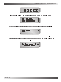
BARRETT 950 HF TRANSCEIVER
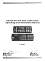
Barrett 950 HF SSB Transceiver
Operating and Installation Manual
© Barrett Communications
BCM95000/1
Head office:
European office:
Barrett Communications Pty Ltd
Barrett Europe Limited
10 Port Kembla Drive, Bibra Lake WA 6163
19 Lenten Street
P O Box 1214, Bibra Lake WA 6965
Alton, Hampshire
AUSTRALIA
GU34 1HG
Toll Free Tel: 1800 999 570
UNITED KINGDOM
Tel: (61-8) 9 434 1700
Tel: (44) 1420 542254
Fax: (61-8) 9 418 6757
Fax: (44) 1420 543373
PAGE 1
BARRETT 950 HF TRANSCEIVER
Introduction ................ ................ ................ ................ ................ ................ ................6
Operation ...................... ................ ................ ................ ................ ................ ................7
Front panel description ........... ................ ................ ................ ................ ................7
Power/volume control ............. ................ ................ ................ ................7
Mic. Socket ............. ................ ................ ................ ................ ................7
Status LED's ........... ................ ................ ................ ................ ................7
Display .................... ................ ................ ................ ................ ................8
Key pad .................. ................ ................ ................ ................ ................9
Channel change ...................... ................ ................ ................ ................ ................10
Channel up/down .................... ................ ................ ................ ................10
Direct channel entry ................ ................ ................ ................ ................10
Selective Calls - alerting other stations ................... ................ ................ ................12
Selcall ..................... ................ ................ ................ ................ ................12
Sending a selcall ..................... ................ ................ ................ ................12
Receiving a selcall .................. ................ ................ ................ ................14
All call ..................... ................ ................ ................ ................ ................14
Group call ............... ................ ................ ................ ................ ................15
Sub group call ......... ................ ................ ................ ................ ................15
Beacon call ............. ................ ................ ................ ................ ................16
Sending a beacon call............. ................ ................ ................ ................16
Receiving a beacon call .......... ................ ................ ................ ................17
Sending an emergency selcall ................ ................ ................ ................18
Transceivers receiving an emergency call .............. ................ ................18
Telcalls - direct dial telephone calls ........ ................ ................ ................ ................19
Beacon call ............. ................ ................ ................ ................ ................19
Sending a Telcall ..................... ................ ................ ................ ................19
Preset dialling ......... ................ ................ ................ ................ ................19
Direct dialling .......... ................ ................ ................ ................ ................21
Last number redial .................. ................ ................ ................ ................23
Hang-up call............ ................ ................ ................ ................ ................23
Scanning channels ................. ................ ................ ................ ................ ................25
Halting scan ............ ................ ................ ................ ................ ................25
Selcall Scan ............ ................ ................ ................ ................ ................26
Signal strength scan (SSL scan) ............. ................ ................ ................26
Voice (syllabic) scan ............... ................ ................ ................ ................26
Enabling channels into scan tables ......... ................ ................ ................27
Clarifier ................... ................ ................ ................ ................ ................ ................28
Mute types .............. ................ ................ ................ ................ ................ ................29
Audio (syllabic) mute ............... ................ ................ ................ ................29
Selcall mute ............ ................ ................ ................ ................ ................29
Signal strength mute ............... ................ ................ ................ ................29
Mode selection ........ ................ ................ ................ ................ ................ ................30
LSB mode ............... ................ ................ ................ ................ ................30
USB mode .............. ................ ................ ................ ................ ................30
AM mode ................ ................ ................ ................ ................ ................30
CW mode ................ ................ ................ ................ ................ ................30
AFSK mode ............ ................ ................ ................ ................ ................30
Alarm operation ...................... ................ ................ ................ ................ ................31
International marine radiotelephone two-tone alarm ............... ................31
RFDS alarm ............ ................ ................ ................ ................ ................31
Testing the alarm .................... ................ ................ ................ ................31
Sending an Alarm ................... ................ ................ ................ ................31
Transmit frequency monitoring ................ ................ ................ ................ ................32
PAGE 2
BARRETT 950 HF TRANSCEIVER
Tune........ ................ ................ ................ ................ ................ ................ ................32
Scrambler ............... ................ ................ ................ ................ ................ ................33
RF output power ..................... ................ ................ ................ ................ ................34
Advanced selective call functions ........... ................ ................ ................ ................35
Requesting another transceivers GPS position ....... ................ ................35
Sending your GPS position to another transceiver ................ ................37
Pagecall .................. ................ ................ ................ ................ ................39
Status selcall (Statcall) ............ ................ ................ ................ ................40
Selective call history ............... ................ ................ ................ ................43
Accessing selcall history ......... ................ ................ ................ ................43
Making a call from the history buffer ....... ................ ................ ................43
Types of selcall history ............ ................ ................ ................ ................43
Tuning receiver ....... ................ ................ ................ ................ ................ ................45
Tuning ..................... ................ ................ ................ ................ ................45
Scanning the tunable receiver ................ ................ ................ ................46
Menu functions ........ ................ ................ ................ ................ ................ ................48
Menus ..................... ................ ................ ................ ................ ................ ................48
Open menu ............. ................ ................ ................ ................ ................ ................48
Identification ............ ................ ................ ................ ................ ................48
Noise blanker .......... ................ ................ ................ ................ ................49
Display back-light levels .......... ................ ................ ................ ................49
Display back-light options ....... ................ ................ ................ ................50
Display options ....... ................ ................ ................ ................ ................51
Battery level ............ ................ ................ ................ ................ ................52
Protected menu ...................... ................ ................ ................ ................ ................53
RF pre-amplifier ...................... ................ ................ ................ ................53
Set Scan Rate ......... ................ ................ ................ ................ ................54
Set Scan Dwell ....... ................ ................ ................ ................ ................54
Set Signal Strength threshold Level (SSL) .............. ................ ................54
External control options .......... ................ ................ ................ ................55
Transmit over beep ............... ................ ................ ................ ................56
Transmit timeout ..................... ................ ................ ................ ................56
Clarifier Limit ........... ................ ................ ................ ................ ................57
Set Selcall I.Ds. ...................... ................ ................ ................ ................57
Set Selcall Pre-amble ............. ................ ................ ................ ................58
External alarm type ................. ................ ................ ................ ................58
Scrambler - hardware option enable ....... ................ ................ ................59
Silent mode ............. ................ ................ ................ ................ ................59
GPS type ................ ................ ................ ................ ................ ................60
500Hz Filter - hardware option enable .................... ................ ................60
Scan resume time ................... ................ ................ ................ ................61
Microphone Up/Down buttons ................. ................ ................ ................61
Cloning and programming transceivers .................. ................ ................62
Cloning ................... ................ ................ ................ ................ ................62
Remote / Local configuration .................. ................ ................ ................66
BITE menu .............. ................ ................ ................ ................ ................67
Transceiver lock ...................... ................ ................ ................ ................69
To lock out (disable) a transceiver ........... ................ ................ ................69
To un-lock a transceiver .......... ................ ................ ................ ................70
Programming functions ................... ................ ................ ................ ................71
Programming steps ................. ................ ................ ................ ................ ................71
PAGE 3
BARRETT 950 HF TRANSCEIVER
Automatic Link Establishment - ALE - option ............... ................76
ALE system overview .............. ................ ................ ................ ................ ................76
Operation overview ................. ................ ................ ................ ................ ................76
Commence ALE scanning ...................... ................ ................ ................ ................77
Receiving an ALE call directed to your transceiver ................. ................ ................78
Calling another ALE station .................... ................ ................ ................ ................79
Making an telephone call via an ALE equipped Barrett 960 telephone
interconnect ........... ................ ................ ................ ................ ................ ................82
Closing an ALE link................. ................ ................ ................ ................ ................85
ALE menus ............. ................ ................ ................ ................ ................ ................86
ALE default ............. ................ ................ ................ ................ ................87
Sounding ................ ................ ................ ................ ................ ................87
Link quality decay time............ ................ ................ ................ ................88
Sounding Signal Length .......... ................ ................ ................ ................89
Bit Error Rate (BER) threshold ................ ................ ................ ................90
Golay threshold ....... ................ ................ ................ ................ ................90
Bad word count ....... ................ ................ ................ ................ ................91
Call Retry Limit ....... ................ ................ ................ ................ ................91
LQA averaging ....... ................ ................ ................ ................ ................92
ALE silent mode ...................... ................ ................ ................ ................93
ALE fill mode ........... ................ ................ ................ ................ ................94
ALE disable ............. ................ ................ ................ ................ ................94
Installation ................... ................ ................ ................ ................ ................ ................95
General ................... ................ ................ ................ ................ ................ ................95
Introduction ............. ................ ................ ................ ................ ................95
Unpacking and inspection ....... ................ ................ ................ ................95
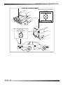
Fixed station installations ........ ................ ................ ................ ................ ................96
Transceiver position ................ ................ ................ ................ ................96
Operating convenience ........... ................ ................ ................ ................96
Air circulation .......... ................ ................ ................ ................ ................96
Proximity of transceiver to antenna ......... ................ ................ ................96
Power supply .......... ................ ................ ................ ................ ................96
Voltage drop............ ................ ................ ................ ................ ................97
Protection fuse ........ ................ ................ ................ ................ ................97
Antenna .................. ................ ................ ................ ................ ................97
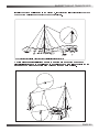
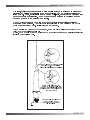
912 Single Wire Broadband Dipoles ....... ................ ................ ................98
912 Multiwire Broadband Dipoles ........... ................ ................ ................100
913 series helical dipoles ........ ................ ................ ................ ................102
915 wire dipole ........ ................ ................ ................ ................ ................104
Barrett 911 Automatic Antenna Tuner for base station installations ........106
Mobile installations ................. ................ ................ ................ ................ ................108
Transceiver position ................ ................ ................ ................ ................108
Safety ..................... ................ ................ ................ ................ ................108
Convenience ........... ................ ................ ................ ................ ................108
Strength .................. ................ ................ ................ ................ ................108
Air circulation .......... ................ ................ ................ ................ ................108
Obstruction ............. ................ ................ ................ ................ ................109
Power wiring ........... ................ ................ ................ ................ ................109
Antenna .................. ................ ................ ................ ................ ................110
Antenna mounting ................... ................ ................ ................ ................110
Antenna feed cables ............... ................ ................ ................ ................110
Voltage standing wave ratio (VSWR) ...................... ................ ................110
Noise suppression .................. ................ ................ ................ ................111
Interference suppression kit .................... ................ ................ ................111
PAGE 4
BARRETT 950 HF TRANSCEIVER
Ignition systems ...................... ................ ................ ................ ................111
Coil to battery wiring ............... ................ ................ ................ ................111
Battery charging system ......... ................ ................ ................ ................112
Alternator / generator to battery wiring .................... ................ ................112
Alternator to regulator control wire .......... ................ ................ ................112
Other regulator wires .............. ................ ................ ................ ................112
Other noise sources ................ ................ ................ ................ ................112
General noise suppression tips ............... ................ ................ ................113
914 series manual tap whip antenna ...................... ................ ................114
910 automatic tuning mobile antenna ..................... ................ ................117
Marine Installations .................... ................ ................ ................ ................ ................121
General ................... ................ ................ ................ ................ ................121
Antenna selection ................... ................ ................ ................ ................121
Antenna .................. ................ ................ ................ ................ ................121
Transceiver and tuner mounting.............. ................ ................ ................121
Ground (earth) system ............ ................ ................ ................ ................121
Corrosion ................ ................ ................ ................ ................ ................122
Portable Operation .................. ................ ................ ................ ................ ................124
Auxiliary connector .............. ................ ................ ................ ................ ................126
Overview of HF operation ............... ................ ................ ................ ................128
Accessories ................ ................ ................ ................ ................ ................ ................132
Accessory interface .................... ................ ................ ................ ................ ................132
Cable assembly .......... ................ ................ ................ ................ ................ ................133
Universal mounting cradle .......... ................ ................ ................ ................ ................133
Fan unit ...................... ................ ................ ................ ................ ................ ................134
Side-plate kits ............. ................ ................ ................ ................ ................ ................135
19" rack mount conversion kit .................... ................ ................ ................ ................136
Interference suppression kit ....... ................ ................ ................ ................ ................137
PAGE 5
BARRETT 950 HF TRANSCEIVER
Introduction
The Barrett 950 transceiver is a sophisticated yet easy to operate, 450 channel HF SSB
transceiver with a frequency range of 1.6 to 30 MHz. Designed to operate in the most arduous
environments, as encountered in off road vehicles, vessels and aircraft, the Barrett 950 will
provide many years of efficient and trouble free service.
The Barrett 950 supports features such as selective call (Selcall), direct dial telephone
connection to base stations fitted with telephone interconnect systems (Telcall) , GPS location,
ALE (Automatic Link Establishment), data transmission and remote diagnostics. These
features
make the Barrett 950 HF transceiver one of the most economical and versatile HF
transceiver available today.
The Barrett 950 transceiver, has catered for the increased use of HF data transmission for
Internet email access and point to point data applications, by providing a comprehensive data
modem interface port, high speed transmit to receive switching, a high stability frequency
standard option and an efficient inbuilt cooling system option.
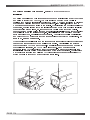
The Barrett 950 transceiver is available in a local (desktop) configuration for base station
applications or in a remote control (trunk mount) configuration for mobile applications. A
combination of both of these configurations allows the 950 to be controlled from two positions,
simultaneously if required.
Operating from 12 volt (13.8 VDC) DC supplies, the transmitter is rated at 125 watt PEP in voice
mode and is protected from over-voltage or reverse voltage application.
All 450 channels are available to be field or workshop programmable. Auxiliary features such as
selcall, telcall, scanning, mute status, alarm system etc. can be individually enabled or disabled
for every channel as required to suit your operation.
Teamed with other matching Barrett 900 series products which include antennas, power
supplies, vehicle tracking packages and HF modems , the Barrett 950 HF transceiver becomes
a powerful tool, providing solutions to many long distance communication requirements.
PAGE 6
BARRETT 950 HF TRANSCEIVER
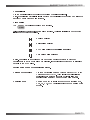
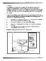
Operation
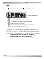
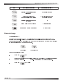
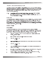
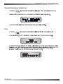
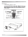
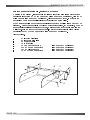
Front panel description
Status LED's
Display
Power/volume knob
ON - VOL
TX
RX
LSB
AM
BARRETT
USB
CHAN 1
CLAR 2
FREQ 3
CHAN
CLAR
FREQ
4
5
6
8
TX FREQ
9
950
MENU
STAT RQ
ALARM
Mic Socket
SEL
TEL
CHAN
SEND
PROG
END
SCRAM
BEACON
MUTE
GPS RQ
TUNE
GPS
CLEAR
MODE
7
Key pad
SCAN
PWR
0
Key pad
Power/volume control
The Barrett 950 transceiver is turned on by rotating this control clockwise. Turn the control
clockwise until volume is set to correct level.
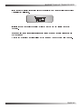
Mic. Socket
The microphone supplied with the Barrett 950 is inserted here.
Status LED's
This group of LED's indicates the mode currently in use. When receiving the green Rx LED
is illuminated, when transmitting the red Tx LED is illuminated. The operating mode of the
transceiver is indicated by the remaining LED's. (i.e. USB, LSB, AM).
PAGE 7
BARRETT 950 HF TRANSCEIVER
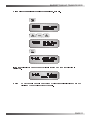
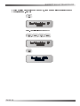
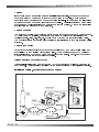
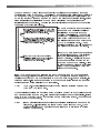
Display
“ ” if scrambler option enabled, “ ” (channel)normally shown
`
Channel Number
Channel usage label
Automatic tuning antenna selected
RF power output section (low power shown)
Mute type (audio mute shown)
Scan table (this channel is assigned to scan table 2)
Selcall format (CCIR 493 format selected)
The Barrett 950 uses a supertwist 2 line by 16 character liquid crystal display (LCD).
The LCD provides the user with current status information of the transceiver including :-
Channel number
Channel frequency
Local characteristics
Channel usage
(parameters unique to the channel in use.)
Global characteristics
PAGE 8
Mode of operation
(parameters that affect all channels.)
BARRETT 950 HF TRANSCEIVER
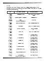
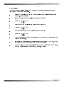
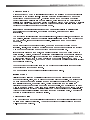
Key pad
There are 20 keys on the keypad. Most keys have multiple functions assigned to them
depending on when the key is pressed. Key functions are listed below followed by a detailed
description of their functions.
Key
Key Primary function
Secondary function
Selcall alarm reset
Menu access, send request
status
Selcall / telcall / ALE initiate
Selcall history
Alarm
Emergency selcall send
Alarm test
Direct channel change
Send selcall / telcall / ALE
Mute select
Send GPS position request
Program channel
Hang-up telcall
Tune mode
Send GPS position data
Channel up
General scroll key
Numeric key 1"
Channel down
General scroll key
Numeric key 4"
Clarifier up
General scroll key
Numeric key 2"
Clarifier down
General scroll key
Numeric key 5"
Receiver tune up
General scroll key
Numeric key 3"
Receiver tune down
General scroll key
Numeric key 6"
Turn scrambler on / off
Numeric key 7"
Mode select
USB, LSB, AM, CW, AFSK
Numeric key 8"
PAGE 9
BARRETT 950 HF TRANSCEIVER
Key
Key Primary function
Secondary function
Display channel transmit
frequency
Numeric key 9"
Start scan, hold for 2
seconds select scan table
Enable / disable scan
Numeric key 0"
Delete character or abort
function
-
High or low power select
Decimal point
Future and custom functions
Beacon call
Channel change
Channel up/down
Pressing the channel up or down key will select respectively the next higher or lower
programmed channel. Holding down either of the keys will cause the rate of the channel
change to increase. The channel up/down keys on the microphone have the same function
as the channel up/down keys on the keypad.
Channel up
Channel down
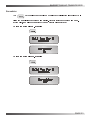
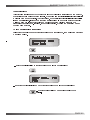
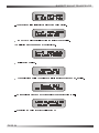
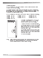
Direct channel entry steps
-
press the
key
-
enter the channel number required, using the numeric keys, channel range is from
1 to 9999 inclusive.
-
PAGE 10
press the
Note:key again
Channel zero cannot be selected .
BARRETT 950 HF TRANSCEIVER
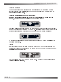
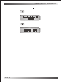
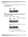
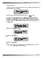
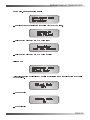
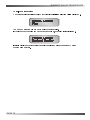
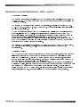
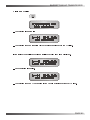
Using direct channel entry to select channel 101- example.
If the channel selected has not been previously programmed then the following is
displayed:-
Note:
Empty channels can only be accessed by direct channel selection and are not
displayed when scrolling through channels.
PAGE 11
BARRETT 950 HF TRANSCEIVER
Selective Calls - alerting other stations
Selcall
Selcall is a digital system of signalling between HF transceivers. Each transceiver is
assigned an individual ID (identification) and can be called using this ID.
Note:-
For selcall functions to operate the transceiver must be fitted with the selcall /
telcall option and the channels enabled for selcall operation.
If ALE is in used refer to the ALE section for details on the integration of the ALE
and normal selcall.
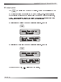
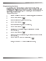
Sending a selcall
-
select the channel on which to send the selcall.
-
listen for traffic on that channel, if no traffic is heard then continue.
-
press the
-
enter the desired destination ID using the numeric keys.
key.
Note:- If you dont enter a new destination ID at this stage and proceed to the next
step the default destination ID ( the last received selcall callers ID or the last
selcall sent ID) will be sent.
-
press the
key.
-
wait for the selective call to be sent.
-
listen for revertive tone from the called station that indicates the call was
successful.
Entering the desired destination ID
Destination ID range is from 0000 to 9999 inclusive (the destination ID
must
be 4 digits
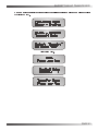
long)
All call*
Group call*
Sub-group call*
*Note:
will be decoded by stations XX00 - XX99 (up to 100 stations)
will be decoded by stations XXX0 - XXX9 (up to 10 stations)
Only available if the destination unit has all call, group call or sub-group call
enabled.
PAGE 12
will be decoded by stations X000 - X999 (up to 1000 stations)
BARRETT 950 HF TRANSCEIVER
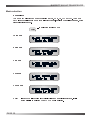
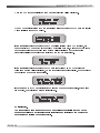
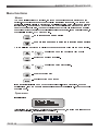
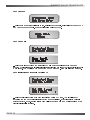
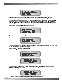
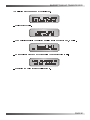
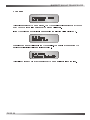
Sending a selcall to station 4321 - example
Note:- Last selcall sent was to 1234
Note:- If no selcall has been programmed on the channel in use an error message will be
generated as indicated below:-
PAGE 13
BARRETT 950 HF TRANSCEIVER
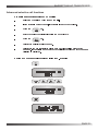
Receiving a selcall
When the transceiver has a selcall enabled channel selected the transceiver monitors
incoming selective calls (selcalls). (If more than one channel is to be monitored then the
scan function should be used.)
Receiving a selcall directed to your transceiver
If an incoming selcall's destination ID matches the unit's selcall ID an audible alarm is
sounded, mute is opened and the display shows the call as follows:
The alarm will sound for thirty seconds and then time out. To stop the alarm before the time
out and acknowledge the call press PTT or any key. If the alarm times out the message "Call
received" will be displayed periodically on the bottom line of the display as follows:
To cancel the "Call received" message either press the clear key or send a selcall back to
the calling transceiver.
All call
If the first digit of the incoming call's destination ID is the same as the unit's selcall ID and
the last three digits of the destination ID are all zero (eg: 9000) then the mute is opened and
the display shows the following:
The mute will stay open for 20 seconds then time out. Once timed out the "Call received"
message will not be displayed.
PAGE 14
BARRETT 950 HF TRANSCEIVER
Group call
If the first two digits of the incoming call's destination ID are the same as the first two digits
of the unit's selcall ID and the last two digits of the destination ID are zero then an audible
alarm is sounded, the mute is opened and the displays shows the call as follows:-
The alarm will sound for three rings in 2 seconds, then leave the mute open for an additional
20 seconds then time out. To stop the alarm and/or the mute open press PTT or any key.
Once timed out the "Call received" message will not be displayed.
Sub group call
If the first three digits of the incoming call's destination ID are the same as the first three
digits of the unit's selcall ID and the last digit of the destination ID is zero then an audible
alarm is sounded, the mute is opened and the displays shows the call as follows:-
The alarm will sound for 5 seconds, then leave the mute open for an additional 20 seconds
then time out. To stop the alarm and/or the mute open press PTT or any key. Once timed out
the "Call received" message will not be displayed.
PAGE 15
BARRETT 950 HF TRANSCEIVER
Beacon call
The "beacon call" function allows the user to determine the signal quality between two
transceivers fitted with the selcall function.
Sending a beacon call
-
select the channel on which to send the beacon call.
-
listen for traffic on that channel, if no traffic is heard then continue.
-
press the
-
enter the desired selcall destination ID using the numeric keys. (xx99 for a
key.
660/960 telephone interconnect, where xx is the 660/960 I.D.)
-
press the
-
wait for the beacon call to be sent.
-
listen for the beacon revertive tones.
-
repeat steps until the channel with the best signal path is found.
Note:-
The beacon revertive tones are different to a normal selcall revertive and are a
series of 4 tones.
PAGE 16
key.
BARRETT 950 HF TRANSCEIVER
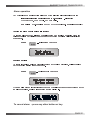
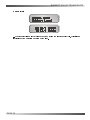
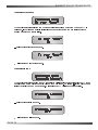
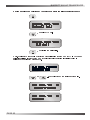
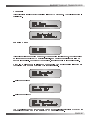
Sending a beacon call to station 4321 - example
Note:- Last selcall sent was to 1234
Receiving a beacon call
When a transceiver receives a beacon request call, it responds by transmitting the beacon
call revertive tones. The beacon request call is not saved in the selcall history buffer.
PAGE 17
BARRETT 950 HF TRANSCEIVER
Sending an emergency selcall
An emergency selcall sequence can be sent from transceivers that have emergency call
channels enabled using the Barrett PC based programming system.
When the emergency call is activated the 950 transceiver sends an selcall, with a specific
emergency call format, twice on each channel programmed in the emergency call sequence
and continues to then repeat this sequence until the transceiver is switched off. If no
emergency channels have been programmed into the transceiver then the emergency call
will be made on the current channel only, but will continue to send emergency calls until the
transceiver is switched off. When a revertive from a receiving transceiver is heard pressing
the PTT will exit the emergency call procedure and stay on the channel the revertive was
heard on.
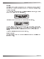
To activate the emergency call sequence:Press
Press
hold for 2 seconds
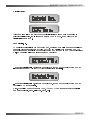
Transceivers receiving an emergency call
Barrett transceivers that receive the emergency selcall emit a distinctive audio alarm and
display the following:-
If the transceiver sending the emergency selcall is fitted with a GPS receiver the position will
also be displayed as illustrated below :-
And:-
PAGE 18
BARRETT 950 HF TRANSCEIVER
Telcall’s - direct dial telephone calls
Transceivers equipped with telcall can direct dial telephone numbers and receive calls from
telephone users through a Barrett 660/960 telephone interconnect system. The 660/960 is a
radiotelephone interface, designed specifically for HF use. The 660/960 allows any Barrett
transceiver fitted with a telcall selective calling facility to access the telephone network
without operator assistance.
Note:-
For telcall functions to operate the transceiver must be fitted with the selcall /
telcall option and the channels enabled for selcall operation.
If ALE is in use refer to the ALE section for details on the integration of the ALE
and normal selcall and telcall.
Beacon call
Channel selection is a critical factor in using the 660/960 telcall system. To enable channels
to be evaluated the 660/960 telephone interconnect has a beacon facility which allows a
station in an HF network to send a special selcall code that causes the 660/960 to send a
beacon signal. The quality of the beacon signal received by the HF out-station is indicative
of the quality of communication that can be expected on the channel in use. (refer to Selcall
(selective call) section - Beacon call).
Sending a Telcall
Preset dialling
To access preset telephone numbers on the Barrett 660/960 a standard selcall is
transmitted from the Barrett 950. The first two digits of the destination ID must be the same
as the first two digits of the 660/960 self ID being called. The second two digits correspond
to one of the 98 preset numbers stored in the 660/960 telephone interconnect.
-
select the channel to be used to make the call (refer to Selcall (selective call)
section -
Beacon call)
-
listen for traffic on that channel, if no traffic then continue
-
press the
-
enter the selcall number corresponding to the preset telephone number required
key
using the numeric keys
-
press the
key
-
when the selcall has finished sending, listen for revertive tones that indicate the
call was successful.
-
if the call was successful then wait for a telephone connection to be made. When
the call has been answered, the user can talk as normal.
-
after the call is complete or the line is busy the user should hang up the line.
(Refer to Selcall (selective call) section -Hang-up
call")
PAGE 19
BARRETT 950 HF TRANSCEIVER
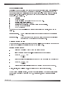
Making a call to preset telephone number 58, via a 660/960 telephone interconnect
whose ID is 6099 - example
Note:- Last selcall sent was to 1234
PAGE 20
BARRETT 950 HF TRANSCEIVER
Direct dialling
To access the direct dialling facility of the Barrett 660/960 telephone interconnect the
transceiver must be fitted with telcall.
-
select the channel to be used to make the call (refer to Selcall (selective call
-
listen for traffic on that channel, if no traffic then continue
-
press the
-
enter the 660/960 destination ID using the numeric keys
-
press the
-
enter the telephone number to dial using the numeric keys
-
press the
-
when the telcall has finished sending listen for revertive tones that indicates the
section - "Beacon
call")
key
key
key
call was successful.
-
if the call was successful then wait for telephone connection to be made. When
the call has been answered, the user can talk as normal.
-
after the call is complete or if the line is busy the user should hang up the line.
(refer to Selcall (selective call) section -
"Hang-up call")
PAGE 21
BARRETT 950 HF TRANSCEIVER
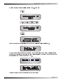
Making a direct dial call to telephone number 61894341700, via a 660/960 telephone
interconnect whose ID is 6099 - example
Note:-Last selcall sent was to 1234
PAGE 22
BARRETT 950 HF TRANSCEIVER
Last number redial
To use the last number redial facility press the
key twice, the last telephone
number sent will now be displayed, now press the
key and the telcall sequence
will be re-sent.
Hang-up call
When a call has been completed the caller must "hang
up"
by sending a hang up code to
the Barrett 660/960.
-
press the
key
-
enter the selcall ID of the 660/960 being called, using the numeric keys
-
press the
-
when the hang-up selcall has completed transmitting, listen for hang-up revertive
key
signal, confirming the hang up was successful, if not heard repeat the above
procedure.
PAGE 23
BARRETT 950 HF TRANSCEIVER
Hanging up call to a 660/960 with ID of 6099 - example
PAGE 24
BARRETT 950 HF TRANSCEIVER
Scanning channels
The Barrett 950 can be programmed to scan up to 450 channels. Pressing the scan key
initiates scanning. Only channels that have been enabled will be scanned. Holding the scan
key down for 2 seconds or more will allow the user to select which scan table is to be
scanned. Use the scroll keys to select the scan table required then press the scan key again
to select it.
Selecting scan table one and initiating scanning - example
... to start scan
To abort scanning press PTT or any other key other than the scan key.
Halting scan
The Barrett 950 will halt scanning for the following reasons:-
The channel has selcall enabled and a selcall signal is received.
-
Signal strength level mute is selected and a signal with a level greater than the
pre-set threshold level is received.
-
Audio (syllabic) mute is selected and a voice signal is detected.
PAGE 25
BARRETT 950 HF TRANSCEIVER
Selcall Scan
When a selcall signal is detected, and the channel has selcall enabled, no matter which
mute type is selected the transceiver will stop scanning and decode the selcall signal.
If the selcall was decoded for this transceiver the audio alarm will sound and the following
will be displayed:-
If no other action is taken, i.e. the transceiver is unattended then the transceiver will
revert to scan and display the following:-
Beeping and alternating with :-
If PTT is operated or any other key, apart from the scan key, is pressed then the
transceiver will select the channel on which the selcall was received as the current
working channel and allow the operator to talk to the station calling.
Signal strength scan (SSL scan)
If the signal strength mute is active and a signal with a level greater than the pre-set
threshold is received the scan will halt. Scan will remain halted while the signal level stays
above the preset threshold. Once the signal decreases below the pre-set threshold level, for
a period greater than the scan dwell period, scanning will resume.
Voice (syllabic) scan
If the audio mute is active and the mute is opened scanning will halt. Scanning will remain
halted while the audio mute is open. Once the mute closes, for a period greater than the
scan dwell period, scanning will resume.
PAGE 26
BARRETT 950 HF TRANSCEIVER
Enabling channels into scan tables in transceivers with channel programming locked
out.
-
Select the channel you wish to enable into the scan table.
-
press the
key
-
press the
key
-
use the
key to select the scan table required by selecting the
symbol corresponding to that scan table. This symbol is displayed on the bottom line of the
display in the 2nd character position.
Scan table 1 enabled for this channel
Scan table 2 enabled for this channel
Scan table 1 & 2 enabled for this channel
No symbol in this position on the display indicates this
channel will not be programmed for scan.
-
press the
key to save this change
PAGE 27
BARRETT 950 HF TRANSCEIVER
Clarifier
The clarifier is used to compensate for received signals that are off frequency.
The receiver can be clarified in steps of 1Hz to frequencies from -1KHz and +1KHz of the
assigned channel frequency, depending on programming. To shift the clarifier use one of the
following keys
or
Pressing either of the above keys once will display the clarifier as follows
Release the key pressed then press it again to begin adjusting the clarifier. Holding the key
down will accelerate the clarifier rate of change until maximum rate of change is achieved or
the clarifier limit is reached. To clear the clarifier value, first bring up the clarifier then press
the
PAGE 28
clear
key to zero the value.
BARRETT 950 HF TRANSCEIVER
Mute types
Pressing the mute key will select the mute function required. A character indicating the mute
function selected is positioned on the second line of the display at the third column from the
left.
Audio (syllabic) mute
When the audio mute is enabled the mute opens only when speech is detected.
Selcall mute
When the selcall mute is enabled the mute opens after a selcall sent to the unit has been
received and decoded successfully.
Signal strength mute
When the SSL mute is enabled the mute only opens when the received signal strength
exceeds the nominated threshold level (see menu functions -
set SSL level").
PAGE 29
BARRETT 950 HF TRANSCEIVER
Mode selection
Mode select
The mode key selects the mode of operation eg LSB, USB, AM, CW or AFSK. The mode
key will temporarily set the mode for a selected channel, until the channel is changed, or the
transceiver is turned off.
... to select the required mode
LSB mode
USB mode
AM mode
CW mode
AFSK mode
Note:
If the 500Hz filter option is physically fitted and enabled in software, it will
automatically be selected when AFSK mode is selected.
PAGE 30
BARRETT 950 HF TRANSCEIVER
Alarm operation
Any channel can be assigned with either one of the following alarm signalling formats
International marine radiotelephone two-tone alarm
- alternating
2200Hz/1300Hz, 500mS cycle, 50% duty cycle.
RFDS alarm
two-tone alarm 880Hz + 1320Hz continuous. (Australian use only)
Testing the alarm (marine alarm illustrated)
To test the alarm encoder, select an channel programmed for alarm operation, press and
release the alarm key within two seconds and the programmed alarm will be audible from
the speaker.
Press
... for less than 2 seconds
Sending an Alarm
To transmit the alarm, select a channel programmed for alarm operation, hold in the alarm
key for a period greater than two seconds.
Press
... for longer than 2 seconds
When an alarm transmit or test is attempted on a channel that has not been programmed for
an alarm operation, no alarm is generated and the display is:-
To cancel alarm - press any other button or key.
PAGE 31
BARRETT 950 HF TRANSCEIVER
Transmit frequency monitoring
When the
is pressed the transceiver will receive on the transmit frequency of a
split transmit / receive frequency channel and the following will be displayed:-
When the key is released the transceiver reverts to normal operation.
Tune
When the
is pressed the transceiver will transmit full power carrier on the
channel selected, at the
Suppressed Carrier Frequency (SCF)
of that channel.
When the tune key is released the display will indicate the forward and reverse power being
delivered to the load (antenna) connected to the transceiver. This giving an indication of the
antenna VSWR. The example below shows a load (antenna) with a poor VSWR,
indicated by a low forward power and the high reverse power:-
PAGE 32
BARRETT 950 HF TRANSCEIVER
Scrambler
The
key toggles the scrambler on or off if the physical scrambler option PCB is
fitted and enabled in the programming section. (refer to protected programming menu Scrambler, and also to the Barrett PC based programming software)
To turn the scrambler on - example
To turn the scrambler off - example
PAGE 33
BARRETT 950 HF TRANSCEIVER
RF output power
The
key toggles the RF output power setting. The high power setting is 125 watt
PEP (voice) and the low power setting is 25 watt PEP (voice). Note:- the transceiver low
power setting is sometimes set to a different value dependant on customer requirements.
Note:If a channel was programmed for low power during channel programming
the selection of high power using the method above is disabled
To select high power if low power was previously selected - example
To select low power if high power was previously selected - example
The lower power symbol,
PAGE 34
, will appear on the display.
BARRETT 950 HF TRANSCEIVER
Advanced selective call functions
Requesting another transceivers GPS position
-
select the channel on which to send the call.
-
listen for traffic on that channel, if no traffic is heard then continue.
-
press the
-
enter the desired destination ID using the numeric keys
-
press the
-
wait for the selective call to be sent.
-
wait for the remote transceiver unit to send back its position data or error
key.
key.
message. If the unit times out before the position is received an error message
will also be displayed.
Making a GPS request call to station with ID 4321 - example
PAGE 35
BARRETT 950 HF TRANSCEIVER
Once the GPS request selcall has been sent the following will be displayed:-
When GPS data is received from the transceiver being requested for GPS data the display
will be similar to that shown below:-
If the transceiver being requested for a GPS position is fitted with a GPS receiver, but
cannot retrieve GPS data from it (due to lack of satellite data etc), a timeout occurs in the
remote transceiver and the following message will be displayed on the requesting
transceiver display on receipt of the reply from the remote transceiver:-
If the transceiver being requested for GPS data is not fitted with a GPS receiver the
following message will be displayed, on the requesting transceiver display, upon receipt of
the reply from the remote transceiver:-
If no response to a GPS request is forthcoming from the remote transceiver, after a fixed
time period, the following message is displayed:-
Special note:The transceiver being requested for GPS data will automatically respond to the
request but will have no visual or audio indications noticeable to the operator or
persons in the vicinity of the transceiver.
PAGE 36
BARRETT 950 HF TRANSCEIVER
Sending your GPS position to another transceiver
-
select the channel on which to send the call.
-
listen for traffic on that channel, if no traffic is heard then continue.
-
press the
-
enter the desired destination ID using the numeric keys
-
press the
-
wait for the selective call to be sent.
-
the remote transceiver unit will send revertive tones confirming its receipt of your
key.
key.
GPS position data. If you do not hear the revertive tone, try again or try another
channel and try again.
Sending your GPS position to a to station with ID 4321 - example
...transceiver is loading data from its GPS receiver.
PAGE 37
BARRETT 950 HF TRANSCEIVER
...transceiver is sending its GPS data.
If the transceiver is fitted with a GPS receiver, but cannot retrieve GPS data from it (due to
lack of satellite data etc), a timeout occurs the following message will be displayed:-
PAGE 38
BARRETT 950 HF TRANSCEIVER
Pagecall
Pagecall is a system that allows messages of up to 32 characters to be sent to a Barrett 950
transceiver from a Barrett 950 transceiver connected to a PC fitted with pagecall software.
Receiving a pagecall
Upon successfully decoding an incoming pagecall an audible alarm is sounded, the mute is
opened and the display shows the call as follows:-
This display is held for 3 seconds then the message received is displayed:-
The alarm will sound for thirty seconds and then time out. To stop the alarm before the time
out and acknowledge the call, activate the PTT or press any other key. If the alarm times out
the display will periodically flash the "call
received "
message on the bottom line of the
display.
To clear the "Call
received "
message press the clear key.
Sending a pagecall
Pagecalls are initiated through the computer control interface refer to the pagecall software
instructions manual.
PAGE 39
BARRETT 950 HF TRANSCEIVER
Status selcall (Statcall)
Statcall is a system that allows the status of any Barrett transceiver fitted with selcall to be
accessed by another Barrett 950 or Barrett 940 transceiver. The status is sent from the
remote transceiver as a selcall with the extra status information stored within the selcall
structure. Information retrieved, that can be used for remote diagnosis of transceiver
performance, is as follows:-
Selcall ID
-
Software version
-
Option level fitted and radio type (950 / 940 / 930 etc.)
-
Receive state battery voltage
-
Last transmit state battery voltage
-
Signal strength indication of received status request selcall.
-
Forward power output level
-
VSWR of antenna
There are two types of statcall that a Barrett 950 transceiver can receive, these are as
follows:-
Status request:-
when a calling transceiver has requested the status of the receiving
unit.
Status revert:-
where a Barrett 950 has sent out a status request and the unit called
has responded by sending back the status bytes.
Receiving a status request
When the Barrett 950 receives a status request the call is not acknowledged to the user but
a status revert call is automatically sent back to the calling unit.
Sending a status request
-
select the channel on which to send the status request
-
listen for traffic on that channel, if no traffic is heard then continue
-
press the
-
enter the desired destination ID between 0000 and 9999 using the numeric keys
-
press the
-
wait for return call containing status to be received and decoded by the 950.
Note:-
key
key
All call, group call and sub-group call numbers will not return a status.
When a status selcall is received, the data is not only displayed on the transceiver display
but output as a series of bytes from the RS-232 interface. (refer
Section )
PAGE 40
Computer Control
BARRETT 950 HF TRANSCEIVER
Making a status request call to station 4321 - example
After the status request selcall has been sent the following will be displayed:-
When the transceiver requested for status has completed its return status selcall and it is
received successfully the status information will be displayed as follows (to step through the
status display frames faster press any key):-
Displays version of software fitted in remote transceiver
PAGE 41
BARRETT 950 HF TRANSCEIVER
Displays supply voltage to remote transceiver during receive and transmit modes.
Displays signal strength of status call received by the remote transceiver and the forward
power transmitted by the remote transceiver when sending the status revert selcall.
Displays the reverse power of the antenna connected to the remote transceiver.
If the transceiver being requested for a status does not respond the display will show the
following message after a timeout period:-
PAGE 42
BARRETT 950 HF TRANSCEIVER
Selective call history
Whenever a selcall, telcall, all call, group call, sub group call, pagecall, statcall or GPS call is
received the callers selcall ID and the channel number the call was received on are stored
in the selcall history buffer. Up to twenty calls can be stored on a first in last out basis.
Accessing selcall history
Select a selcall channel
... for at least 2 seconds.
Now release the selcall key and the transceiver will be in selcall history mode. Use the
general scroll keys to scroll through the available selcall history. If there is no selcall history
then the following message will appear on the display:-
To abort selcall history mode activate PTT or press the clear key. If there is selcall history
the top line of the display shows the channel the call was received on, the selcall ID of the
calling unit and the history buffer count.
Making a call from the history buffer
To make a call when scrolling through the selcall history buffer perform the following steps:-
select the call to be answered with the scroll keys
-
press the send key
The Barrett 950 transceiver will change to the channel the logged call was received on and
initiate a call sequence.
Types of selcall history
Normal selcalls, all calls, group calls and sub group calls are all displayed in the following
format in selcall history :-
Telcalls are displayed as follows
:-
PAGE 43
BARRETT 950 HF TRANSCEIVER
Pagecalls are displayed as follows :-
... to display pagecall message:-
Statcalls are displayed as follows:-
... to display statcall information:-
Etc.
PAGE 44
BARRETT 950 HF TRANSCEIVER
Tuning receiver
The 950 transceiver can be used as a tunable receiver. The receiver can be tuned in steps
ranging from 1 Hz up to 10 MHz.
Entering tuning receiver mode
or
Tuning
To tune the receiver use the clarifier keys to position the cursor under the digit representing
the frequency increment required then use the frequency up or down key to tune the
receiver at the increment selected.
Tune receiver from 10000.000 kHz to 10500.000 kHz - example
or
to position cursor under digit to change
... until 5 is displayed in the digit position above the cursor
When you have finished using the tuning receiver
press the
key to return to the previous operating channel.
PAGE 45
BARRETT 950 HF TRANSCEIVER
Scanning the tunable receiver
The Barrett 950 can scan any range of frequencies from 500 KHz to 30 MHz with a
frequency step down to 1 Hz.
Setting up scan frequencies
To set up the frequency scan parameters on the Barrett 950, enter the tuning receiver mode,
then:-
... hold down until the following is displayed:-
Enter a new frequency, using the numeric keys, to set the first scan limit boundary - example
below shows Scan Limit 1 set to 12 MHz:.
... until display below appears
Note:-
The frequency of 12000.000 may not appear as shown above, this indicates the
last scan limit boundary programmed was 12000 kHz which will not always be the
case
PAGE 46
BARRETT 950 HF TRANSCEIVER
Enter a new frequency, using the numeric keys, to set the second scan limit boundary - the
example below shows Scan Limit 2 set to 30 MHz:-
... until display below appears
Enter the step increment required in Hz i.e. entering 100 will select scan increments of
100 Hz.
... the display will revert to the tuning receiver display :-
... will commence scanning using the parameters set above:-
The transceiver will halt scanning for the following reasons:
-
Signal Strength Level (SSL) mute is selected and a signal with a level greater
than the pre-set threshold is received.
-
Audio (syllabic) mute is selected and a voice signal is detected.
PAGE 47
BARRETT 950 HF TRANSCEIVER
Menu functions
Menus
The menu is divided into two sections, the open menu section and the protected menu
section. Both sections are used to set or display transceiver parameters. The open menu
section is available directly to operators as no critical operation parameters can be changed
in this section. The protected menu section has some critical parameters and you need a
password to enter this area. The password is fixed and very simple but is used as a barrier
to stop inadvertent changing of the critical transceiver parameters. It can be totally barred, if
operationally required, by PC programming.
to enter the open menu section
for more than 2 seconds to enter the protected menu section
Use the following sequences to display or change parameters of items in the menu section.
or
to select the menu item required to view or edit
... enters the menu item for editing.
or
to select the parameter required.
... to save the parameter
... to exit out of the menu system
If the transceiver is left in menu mode the transceiver will, after a preset time, sound an
audible alarm, flash the message "use
scroll keys"
and eventually time-out back to normal
operating mode.
Open menu
Identification
This displays the transceiver model, software version number, the option pack fitted and the
transceiver selcall ID, (if selcall is fitted) as follows :-
PAGE 48
BARRETT 950 HF TRANSCEIVER
Noise blanker
This menu item allows the user to enable or disable the noise blanker on the transceiver.
The noise blanker is used to reduce repetitive impulse noise.(eg vehicle ignition noise)
... selects noise blanker on
... selects noise blanker off
Display back-light levels
... selects display back-light intensity level 1
... selects display back-light intensity level 2
... selects display back-light intensity level 3
PAGE 49
BARRETT 950 HF TRANSCEIVER
Display back-light options
... selects a display back-light time out time of 5 seconds from last key press
... selects a display back-light time out time of 30 seconds from last key press
... selects display back-light always on.
... selects display back-light always off.
PAGE 50
BARRETT 950 HF TRANSCEIVER
Display options
selects the display the channel usage information in both receive and transmit.
... selects the display of signal strength level in receive and the channel usage information in
transmit.
... selects the display of channel usage information in receive and the forward power level in
transmit.
... selects the display of signal strength level in receive and forward power level in transmit.
PAGE 51
BARRETT 950 HF TRANSCEIVER
Battery level
... the transmit voltage is the voltage recorded during the last transmit cycle, this giving a
indication of the batteries capacity under load.
PAGE 52
BARRETT 950 HF TRANSCEIVER
Protected menu
Refer to page 48 for the method of entry and the method to display or change parameters of
items in this protected menu section.
Enter the password using the numeric keys, then press the
key.
The password is 1234. Note:- the password is published as it is only used to provide
protection from making inadvertent changes to more critical parameters during normal
operation of the transceiver. If no access to protected menus is to be allowed to operators,
the protected menus can be barred using the Barrett PC based programming system.
RF pre-amplifier
Selects the RF pre-amplifier on or off.
... selects RF Pre-amplifier on
... selects RF Pre-amplifier off
Note:-
In later versions of 900 series transceivers this function has been removed and
the RF Pre-amplifier is always switched on.
PAGE 53
BARRETT 950 HF TRANSCEIVER
Set Scan Rate
... selects the scan rate applicable to non-selcall scan channels, selectable between 100mS
and 5 seconds per channel - the example below selects 500mS.
Set Scan Dwell
... selects the length of time the transceiver dwells on a channel after scan has been
stopped by signal strength level (if signal strength level mute is set) or voice activity (if audio
mute is set). The dwell time can be set from 1 to 10 seconds - example selects 5 seconds.
Set Signal Strength threshold Level (SSL)
... select the level at which scan stop is activated during SSL scan. The level is set by
adjusting the number of signal strength arrows on the display - example selects 5 signal
strength arrows. Note:- setting this to high will prevent the mute from opening unless a very
high level signal is received.
PAGE 54
BARRETT 950 HF TRANSCEIVER
External control options
... enables the use of a Barrett 516/916 antenna select units or external devices requiring
BCD coded channel information. (0000 = Channel 1, 0001= Channel 2, 0010 = Channel 3
etc to 1111 = Channel 16)
Note:-
This option disables the external alarm operation - all the
options below have the external alarm enabled.
... enables the use of a Barrett 510/910 Automatic Tuning Mobile Antenna.
... enables the use of a Barrett 511/911 Automatic Antenna Tuner
... enables the use of Barrett 975 series linear amplifiers.
...this feature enables the use of the optional second antenna socket that can be fitted to the
rear of the 950 transceiver. When this option is selected and a jumper on the PA PCB is
fitted, as described in the 950 technical manual, the transceiver receive input and
transmitter output is directed to either Antenna socket 1 or Antenna socket 2 on a channel
by channel basis as dictated by channel programming i.e. ANT1 or ANT2 selected.
Note:- Any antenna not requiring transceiver control can be used with the "Aux
option. I.e. Base station antennas, 914 manual tapped whip antennas etc.
ant fitted"
PAGE 55
BARRETT 950 HF TRANSCEIVER
Transmit over beep
When this feature is selected the 950 transceiver transmits a short tone when the PTT is
released. It provides an audible indication to the operator at the remote station that the
station has stopped transmitting.
... selects transmit over beep on.
selects transmit over beep off.
Transmit timeout
When this feature is enabled the 950 transceiver will disable the transmitter if the PTT (push
to talk button on the microphone) is held on for more than 1.5 minutes i.e. if the microphone
is inadvertently jammed under a seat. Releasing the PTT will reset the transmitter.
... selects transmit timeout on.
selects transmit timeout off.
PAGE 56
BARRETT 950 HF TRANSCEIVER
Clarifier Limit
This menu item allows the user to set the clarifier limits on land mobile channels with
selective call disabled , the limits can be set from 50Hz to 1KHz - example shows the
clarifier limit set to 150Hz.
Set Selcall I.Ds.
Two selective call self IDs can be programmed, one is the normal ID used as the self ID on
channels with Barrett standard or CCIR 493 (WA2 in Australia) format programmed. The
second is used as the self ID on channels programmed for use with RDD (Radphone Direct
Dial, an Australian telephone interconnected HF service)
... enter the selcall self ID1, using the numeric keys, for use on channels programmed for
Barrett standard and CCIR 493 (WA2 in Australia ) format selcall.
... enter the selcall self ID2, using the numeric keys, for use on channels programmed for
Australian RDD format selcall.
Note:- the self ID must not be set to X000, XX00 or XXX0 as these are reserved selcall
numbers for all call, group-call or sub-group-call.
PAGE 57
BARRETT 950 HF TRANSCEIVER
Set Selcall Pre-amble
Sets the length of the selcall preamble. The length of preamble is set dependant on the
number of channels being scanned. The preamble can be set from 1 to 10 seconds. Allow
500mS for each selcall channel to be scanned plus one second, E.g. to scan 8 selcall
channels :- 500mS x 8 + 1 sec. = 5 seconds - the example below illustrates a pre-amble
time set to 5 seconds.
External alarm type
... selects which type of alarm signal is generated on the External Alarm, pin 17 on the
auxiliary connector.
... selects latched alarm, the alarm output will be continuously active for 30 seconds and
then turn off. This sequence will occur unless the PTT is activated or the clear key is
pressed during the sequence.
... selects the pulsed alarm, the alarm will turn on after 15 seconds and remain on for 15
seconds, then will turn off. This sequence will occur unless the PTT is activated or the clear
key is pressed during the sequence.
PAGE 58
BARRETT 950 HF TRANSCEIVER
Scrambler - hardware option enable
...enables software control of the scrambler hardware when fitted.
... selects scrambler hardware PCB option fitted
... selects scrambler hardware PCB option not fitted
Silent mode
This option enables or disables any audible annunciation tones associated with front panel
key operation.
... tones enabled
... tones disabled
PAGE 59
BARRETT 950 HF TRANSCEIVER
GPS type
Selects which type of GPS receiver is to be used for position information, either the
internally fitted GPS receiver option Barrett P/Ns BCA90030 or BCA95002 or an external
GPS receiver connected to the NMEA 0183 compliant port on pins 8 and 20 of the auxiliary
connector. Note:- when an external GPS is connected the functions normally associated
with pin 8, linear amplifier ALC input and pin 20, auxiliary digital input are disabled and not
available. Note: the external GPS receiver must be outputting the NMEA 0183 RMC
sentence to be compatible with the Barrett 950.
... selects internal GPS receiver, if the internal GPS receiver is installed
... selects external GPS receiver, if an external GPS receiver is connected to the NMEA port
on the transceiver s auxiliary connector .
500Hz Filter - hardware option enable
... select if 500Hz filter option is fitted to the transceiver, this will cause the hardware to
select this filter in AFSK mode.
select when 500Hz filter option
PAGE 60
is not fitted
to the transceiver.
BARRETT 950 HF TRANSCEIVER
Scan resume time
Enabling this feature, by specifying a scan resume time, the Barrett 950 transceiver will
resume scanning the scan table previously selected at a time after the last key press
specified by the scan resume time selected. The example below will cause the 950
transceiver to resume scanning 1 minute after the last key press :-
Microphone Up/Down buttons
The channel up/down buttons on the microphone can be enabled or disabled using this
function.
... microphone up/down buttons enabled
... microphone up/down buttons disabled
PAGE 61
BARRETT 950 HF TRANSCEIVER
Cloning and programming transceivers
This feature in the 950 transceiver is used to copy the configuration of one 950 transceiver
to another using the serial interface on the rear 25 pin D connector or to receive
programming information from the Barrett PC based 900 series transceiver programming
system.
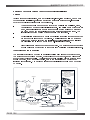
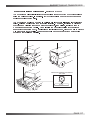
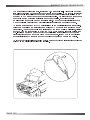
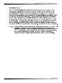
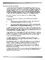
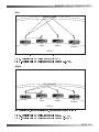
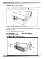
Cloning
The following steps are necessary to copy the configuration of one 950 transceiver to
another :-
Fit the DB25" to DB25" cloning cable, Barrett P/N BCA90024 to the auxiliary
connector on each transceiver.
-
Switch on both transceivers.
Picture of two transceivers connected together with cloning lead
PAGE 62
BARRETT 950 HF TRANSCEIVER
On the master transceiver (transceiver containing the information to be cloned)
select
the cloning menu:-
Alternating with:-
PAGE 63
BARRETT 950 HF TRANSCEIVER
On the slave transceiver (transceiver to receive information)
select the cloning menu:-
Now the two selcall self IDs of the slave transceiver must be entered:-
Enter selcall self ID1, using the numeric keys, for use on channels programmed for Barrett
standard and CCIR 493 (WA2 in Australia ) format selcall.
Enter selcall self ID2, using the numeric keys, for use on channels programmed for
Australian RDD format selcall.
Note:- the self ID must not be set to X000, XX00 or XXX0 as these are reserved selcall
numbers for all call, group-call or sub-group-call.
PAGE 64
BARRETT 950 HF TRANSCEIVER
If the transfer of cloning information is unsuccessful both the master and slave transceiver
will display the following:-
If this is the case the cable connection should be checked and the cloning procedure
repeated.
Programming a 950 transceiver using the Barrett PC based programming software
P/N BCA90035
Refer to the operating manual supplied with the Barrett PC based programming software.
PAGE 65
BARRETT 950 HF TRANSCEIVER
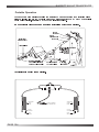
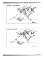
Remote / Local configuration
This feature allows the Barrett 950 transceiver to be used in remote site configurations using
other 900 series Barrett products such as the 972 remote site controllers and the 974
system integration system
... selects local receive and local transmit, i.e. normal transceiver operation.
... selects remote receive and local transmit, i.e. the transceiver transmits through the local
antenna but the receive signal is input as an audio signal from a remote receiver through the
600 ohm balanced audio input port on pin 11 and 24 of the accessory connector on the rear
of the 950 transceiver.
... selects local receive and remote transmit, i.e the transceiver receives through the local
antenna but the transmitter is disabled and transmit audio is output to modulate a remote
transmitter through the 600 ohm balanced audio output port on pin 12 and 25 of the
accessory connector on the rear of the 950 transceiver.
.
... selects both of the states above. i.e. the 950 transceiver operates as a console not as a
transmitter and receiver.
PAGE 66
BARRETT 950 HF TRANSCEIVER
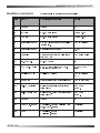
BITE menu
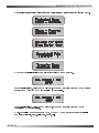
The BITE menu allows the user to self test different functions of the 950 transceiver. There
are four BITE functions that can be tested as illustrated below :-
... receiver basic function test, this sets the transceiver so a known internal signal source is
present in the receiver, a signal strength is recorded, the level of which is used to confirm
the receiver is functioning.
... selcall decoder test, an internally generated signal is generated in the receiver on the
mark and space frequencies of the selcall decoder. The test checks that the selcall decoder
output is correct with respect to the mark and space frequencies.
... audio mute test, an internally generated signal is generated, the test checks that the
audio mute opens in response to this signal.
... receiver SSL mute test, an internally generated signal is generated in the receiver . The
test checks that the SSL mute opens in response to this signal.
PAGE 67
BARRETT 950 HF TRANSCEIVER
... ALE test, if the ALE option is fitted, the test checks communications to the ALE processor.
... RS-232 test, a plug must be fitted to the auxiliary connector with pins 2 and 3 connected
together. This test checks that the RS-232 port is operational.
... VCO lock test checks that the VCO remains in lock to a channel frequency of 30.5MHz
If the above tests pass the following is displayed :-
If the tests fail the following is displayed :-
PAGE 68
BARRETT 950 HF TRANSCEIVER
Transceiver lock
This function enables a network operator to lock out (disable) a transceiver on the network,
that for instance is being operated illegally, by sending it a special selcall (selective call) with
a disable code embedded in it. The transceiver, upon receiving this selcall (selective call) is
locked out (disabled). It cannot be operated again until a PIN number is entered correctly
within 10 attempts. If the correct PIN number is not entered within 10 attempts, the
transceiver can only be re-enabled, for normal operation, by using the Barrett PC based
programming software.
To lock out (disable) a transceiver
Select the channel you suspect the transceiver to be operating on, then select the protected
menu item below:-
.
... enter the selcall self ID or the transceiver to be locked out (disabled)
... enter the confidential pin number of the transceiver to be locked out (disabled)
... the transceiver will now be sending the lock out
selcall.
PAGE 69
BARRETT 950 HF TRANSCEIVER
To un-lock a transceiver
On the transceiver receiving the lock out (disable) selcall the following will be displayed :-
You can now enter the pin number to unlock the transceiver.
If you input the wrong PIN number more than 10 times, the following is displayed :-
If this is displayed the transceiver can only be unlocked using the Barrett PC based
programming software.
PAGE 70
BARRETT 950 HF TRANSCEIVER
Programming functions
950 transceivers will be delivered in a locked or unlocked state depending on local
legislative requirements. If your transceiver is unlocked proceed as described below using
the internal programmer, if locked you must use the 950 dealer PC based software system.
950 transceivers may however be cloned, even when locked, from each other using the
cloning cable. (see cloning section)
Programming steps
-
select the channel to be programmed (Operation section - direct channel change)
-
press the programming key
-
enter the receive frequency, using the numeric keys.
-
press the programming key
-
enter the transmit frequency, using the numeric keys.
-
press the programming key
-
select first page of channel parameters, see setting first page of channel
parameters below.
-
press the programming key
-
select second page of channel parameters, see setting second page of channel
parameters below.
-
press the program key to store the new information
Note :-
The microphone PTT or clear key will abort the change.
PAGE 71
BARRETT 950 HF TRANSCEIVER
Setting the first page of channel parameters :Selcall enable and format select
The
key selects the selcall format required for the channel being
programmed. Select the letter or symbol corresponding to the selcall format required. This
letter or symbol is displayed on the bottom line of the display in the 1st character position.
Barrett Australia format selcall is selected.
CCIR 493 (WA2 Australia) format selcall is selected.
Australian RDD format selcall is selected.
When no letter or symbol is displayed in this position, no selcall is selected on the channel
being programmed.
Scan enable
Use the scan key to select the scan table required. Select the symbol corresponding to the
scan table required. This symbol is displayed on the bottom line of the display in the 2nd
character position.
Scan table 1 enabled for this channel
Scan table 2 enabled for this channel
Scan table 1 & 2 enabled for this channel
No symbol displayed in this position indicates this channel will not be programmed for scan.
Low power
The
key selects the RF power setting required.
The low power symbol
will be displayed on the bottom line in the 4th character position.
when low power is selected for this channel. No symbol in this position indicates that normal
high power is selected.
PAGE 72
BARRETT 950 HF TRANSCEIVER
Channel label
Use the general scroll keys to select the required channel usage label.
Note:- the selection of available labels depends on what labels were programmed using the
Barrett PC based programming software.
Alarm setting
The
key selects the alarm type required.
Select the letter corresponding to the alarm required. The letter is displayed on the bottom
line in the 3rd character position.
No alarm selected
Marine alarm selected
RFDS alarm selected
(Australian use only)
User defined alarm selected
Note:-
User alarm is an option and can be programmed in the factory to customer
requirements to any two tone alarm combination, if the option is not programmed this alarm
defaults to the RFDS alarm.
Setting second page of channel parameters :Antenna Socket Select
The tune key toggles between Antenna socket 1(ANT 1) and
Antenna socket 2 (ANT2). This will only be available if the
optional second antenna socket is physically fitted and
enabled using Barrett PC based programming software.
Operating mode
Use the mode key to toggle through to mode required (LSB,
USB, AM, CW, AFSK) as indicated in the mode section of the
screen.
PAGE 73
BARRETT 950 HF TRANSCEIVER
Programming example
Programming channel 101 to 6850.0 KHz, lower sideband, selcall enabled, entry of the
channel into scan table one, low power on transmit, RFDS alarm and label 'BARRETT'.The
example assumes that channel 101 was already selected by direct channel selection (see
Operation section - direct channel change) and was not previously programmed.
... to enable selcall
PAGE 74
BARRETT 950 HF TRANSCEIVER
... to enable scan table one
until 'R' is shown, to select RFDS alarm
to select low power
or
to select channel label
until LSB is displayed
PAGE 75
BARRETT 950 HF TRANSCEIVER
Automatic Link Establishment - ALE - option
ALE system overview
The Barrett Automatic Link Establishment (ALE) controller option simplifies the operation of
HF networks, the ALE option automating many of the procedures necessary to establish and
maintain an HF link.
The Barrett ALE controller option provides complete inter-operability as required by FEDSTD-1045 and U.S. MIL-STD-188-141A standards. The option is installed internally within a
Barrett 950 transceiver.
HF network stations equipped with ALE controllers automatically scan a preselected set of
channels, listening for ALE calls. If sounding is selected stations at random send out
sounding calls to other stations. These signals are analysed for link quality and stored in
the sounded stations. All stations gradually build up a table of parameters which
determines best channels to use to link between specific stations. These tables are used by
the a ALE controller to determine the best channel to connect on when commanded by its
operator to communicate with another station.
The Barrett ALE controller s powerful memory stores up to 10,000 sets of LQA information,
100 channel configurations, 20 self-address configurations and 100 other address
configurations.
Operation overview
The ALE network parameters are determined by a network supervisor, this person programs
all the transceivers in the network with the required addressing and channel information
using the ALE fill program. This is a PC based program used to transfer pre-determined
network information into each transceiver. A separate manual is provided as a guide to ALE
network setup and for the operation of ALE fill program.
As ALEs prime purpose is to automate many of the procedures necessary to establish and
maintain an HF link, it is only necessary for the operator to enter the station he wishes to call
and activate ALE call sequence as described in the following section. There is also the
facility to change some ALE parameters, this is not usually done in the field and sometimes
this section is locked out. The section titled ALE menus describes these functions.
PAGE 76
BARRETT 950 HF TRANSCEIVER
Commence ALE scanning
... key for 2 seconds
or
... to select the scan type required.
... to select this (ALE) scan type.
to commence ALE scanning.
... your transceiver will now be ALE scanning and ready to accept ALE calls, receive
soundings and transmit soundings, if soundings are enabled on your transceiver.
Whilst ALE scanning the following messages may be displayed:-
... occurs when your station receives and ALE sounding from another station in the network.
... occurs when your station transmits a sounding, your station would have sounding
enabled.
PAGE 77
BARRETT 950 HF TRANSCEIVER
Receiving an ALE call directed to your transceiver
... a station is calling you and you are transmitting back linking information.
... your station is now receiving more linking information from the calling station.
.
... the link is successful, an audible alarm will sound after which you can start
communication with the station that called you.
... the link was unsuccessful.
you are linked to another station and you attempted to change channels.
PAGE 78
BARRETT 950 HF TRANSCEIVER
Calling another ALE station
... to select ALE call.
... to display the station list.
Note:- the previous two steps only occur if the channel is also programmed for CCIR-493
based selective call use, if not programmed for selective call the station list display below is
selected by the first key press above:-
or
...to scroll through the station address list.
PAGE 79
BARRETT 950 HF TRANSCEIVER
Either
or
Or
select a new self ID.
to this point if using the default self ID.
... the ALE call sequence has commenced.
... you are waiting for a response the called station.
... the called station has replied and you are acknowledging.
... you now have a link established with the station you are calling.
PAGE 80
BARRETT 950 HF TRANSCEIVER
The following error messages may be displayed:-
... the link attempt failed.
... when selecting a self ID you selected a self ID that is not programmed, a null ID.
... no channels are programmed for the station you are attempting to call.
... the station you called rejected the link attempt.
PAGE 81
BARRETT 950 HF TRANSCEIVER
Making an telephone call via an ALE equipped Barrett 960 telephone interconnect
to select ALE call.
to display the station list.
Note:- the last two steps only occur if the channel is also programmed for CCIR 493 based
selective call use, if not programmed for selective call the station list display below is
selected by the first key press above:-
or
PAGE 82
...to scroll through the station address list.
BARRETT 950 HF TRANSCEIVER
Either
or
Or
select a new self ID.
... to this point if using the default self ID
... the ALE call sequence has commenced.
PAGE 83
BARRETT 950 HF TRANSCEIVER
... you are transmitting linking information to the called station.
you now have a link established with the station you are calling.
The following error messages may be displayed:-
the link attempt failed.
when selecting a self ID you selected a self ID that is not programmed, a null ID.
... no channels are programmed for the station you are attempting to call.
... the station you called rejected the link attempt
PAGE 84
BARRETT 950 HF TRANSCEIVER
Closing an ALE link
... your station closes the link
... your station resumes scanning (if you were in scanning before the ALE link).
If the station you are linked to closes the link the following will be displayed:-
... remote station closes link.
... your station resumes ALE scanning (if you were in scanning before the ALE link).
PAGE 85
BARRETT 950 HF TRANSCEIVER
ALE menus
This option enters the ALE menu system. The ALE controller option Barrett P/N BCA95001
or BCA95002 must be fitted before the ALE system will operate.
If the ALE option has not previously been enabled the following will be displayed :-
Pressing the menu key will enable the ALE controller. The next time you enter the ALE
section the first display will be as indicated below :-
This will now appear when ever you enter the ALE menu as it is the first menu item.
PAGE 86
BARRETT 950 HF TRANSCEIVER
ALE default
This option is to reselect factory defaults within the ALE processor. The following screen is
0displayed:-
Sounding On/Off
This option switches sounding on and off. When sounding is switched off, your transceiver
no longer send or receives ALE sounding signals, and cannot update its in formation on
network link analysis. For correct ALE operation, sounding should be left on all the time.
Note :- If ALE silent mode is selected on, the sounding On/Off option setting is ignored and
your station does not send or receive ALE sounding signals.
... selects sounding on
... selects sounding off
The ALE select Sounds Off Or Sounds On on a channel basis determined by the way the
channel was programmed by the Barrett ALE PC based fill program.
PAGE 87
BARRETT 950 HF TRANSCEIVER
Link quality decay time
This option sets the artificial decay time for the link quality information that is stored in the
link quality table within the ALE processor.
The decay can be disabled or set to between 1 and 8 hours.
Switching the sounding off and setting a decay time of two hours would result in the record
of a perfect channel (100% channel quality) decaying to an unusable channel (0% channel
quality) over a period of two hours .
PAGE 88
BARRETT 950 HF TRANSCEIVER
Sounding Signal Length
This option sets the length of the sounding transmission, in seconds, for each channel in the
scan group.
When an ALE station sends sounding signals, a separate signal is transmitted for each
channel in the scan group. The ALE station sends these signals sequentially. The total
length of the sounding transmission is the product of the sounding signal length and the
number of channels.
If the sounding signal length is set to 10 seconds and the scan group contains seven
channels, the ALE station takes 70 seconds to complete sounding transmission.
The default sounding signal length is the minimum setting (under five seconds). The
maximum setting is 100 seconds.
PAGE 89
BARRETT 950 HF TRANSCEIVER
Bit Error Rate (BER) threshold
This option sets the value of the BER threshold used in the BER testing routine.
The value can be set in the range 0 to 48.
BER testing is a method of error detection for ALE word transmission. ALE stations send
and receive ALE link controlling information in blocks of data called ALE words. An ALE
word consists of a 3-bit preamble and a 21-bit data field.
The result of BER error testing is used as part of the decision process to determine if an
ALE link can be established using the current channel.
The higher the BER value of a transmitted ALE word, the greater the error. A BER value of
0 indicates perfect reception of an ALE word. The maximum BER value of 48 indicates that
all bits of the ALE word were bad.
If a received ALE word contains more errors than the BER Threshold, the ALE processor
rejects the word.
Golay threshold
This option sets the value of the Golay threshold used in Golay testing.
Golay testing is an additional method of error detection for ALE word transmission. The
result of the Golay testing is used as another part of the decision process to determine if an
ALE link can be established using the current channel.
The higher the Golay value calculated for a received ALE word, the greater the error.
The value can be set between 0 and 4.
PAGE 90
BARRETT 950 HF TRANSCEIVER
Bad word count
This option sets the maximum number of sequentially received bad ALE words which are
allowed before the ALE processor decides that the quality of the current channel is too poor
to establish an ALE link. A bad word is a word that has exceeded either the BER or Golay
Threshold.
The value can be set between 0 and 4.
If the test fails during the process of establishing the ALE link, the call aborts and the
transceiver returns to scan mode.
Call Retry Limit
This option controls the number of times the ALE station tries to establish an ALE link using
each channel in turn form the scan group.
The limit can be set between 0 and 98. If 99 is selected this is interpreted as no limit.
On each selected channel, two attempts are made to establish a link before going onto the
next preferred channel, where two more attempts are made and so on, until all channels in
the scan table have been tried (unless a link is established).
The sequence is then repeated dependent upon call retry limit set above.
Note: Retry duration can be made up to one minute per channel.
PAGE 91
BARRETT 950 HF TRANSCEIVER
LQA averaging
This option sets the method used to update an existing link quality value stored in ALE
processor memory when the new link quality value is worse than the stored value.
The option can be set to :-
replace the old values with the new values
-
replace the old values with different weighted averages of the old values and new
readings.
Averaging reduces the effect that one bad reading might otherwise have on a perfect
channel. If a new reading is better than an old value, the old value is replaced by the
reading. There are different averaging formulas available as indicated below :-
Averaging formula 1
Averaging formula 2
Averaging formula 3
Replace the old values with the new readings
PAGE 92
BARRETT 950 HF TRANSCEIVER
ALE silent mode
This option selects the silent mode of operation required.
ALE operates normally both transmitting and receiving sounds (if enabled).
ALE transmit mode is disabled (silent mode), the ALE controller does not respond to
incoming ALE calls and does not send or receive sounding signals even if sounding is
switched on.
Note:- You can still make ALE calls in this mode.
The ALE will operate as described in the mode above but only on channels programmed for
Tx disable mode(silent mode) by the Barrett ALE PC based fill program.
PAGE 93
BARRETT 950 HF TRANSCEIVER
ALE fill mode
This option is used to enable the 950 transceiver to accept network data from the
Barrett PC based ALE fill program. Refer to the Barrett ALE fill software manual for
details.
ALE disable
This option will disable the ALE option.
PAGE 94
BARRETT 950 HF TRANSCEIVER
Installation
General
Introduction
This handbook provides instructions for the installation of land based HF communication
equipment. The contents cover both base station and mobile installations.
Most of the installation work can be performed by non-technical personnel if they carefully
follow the instructions given in this handbook. It is however recommended that the
completed installation be checked by a suitably qualified technician. In some equipment
configurations, technical adjustment is required for the equipment to operate correctly.
Note:-
Some equipment has specific instructions supplied with it. When this occurs
those instructions over-ride the general guidance of this handbook, and must be
followed in detail.
Unpacking and inspection
When unpacking the transceiver, check the contents against the packing note provided.
Before discarding the carton, check that all accessories have been removed and are not
mislaid in the packing material. Inspect the equipment for any transit damage. If damage
has occurred notify your supplier immediately and gain their advice on further action. Failure
to do this could affect the warranty covering the equipment.
PAGE 95
BARRETT 950 HF TRANSCEIVER
Fixed station installations
Transceiver position
The following should be considered when choosing a position for the transceiver.
Operating convenience
The transceiver should be placed so that the operator is comfortable and any facilities he
may require can be easily accessed.
Air circulation
Most transceivers rely on air flow around cooling fins to dissipate heat generated by the
transmitter. The mounting position must allow free air flow around these fins.
Proximity of transceiver to antenna
When using RG-58 coaxial cable from the transceiver to the antenna a cable length of no
more than 30 metres is recommended. Should a run of more than 30 metres be required it is
recommended that a low loss coax such as RG-213 or RG-8 be used.
It is recommended that the transceiver chassis is connected to ground using the bolt on the
rear panel to stop pick-up of unwanted noise from local power supplies and electrical
equipment.
Power supply
All Barrett transceivers require a supply voltage of 13.8 VDC . In most vehicles or vessels
this is available from the battery, in the case of vehicles with a 24V system a 24V to 12V
converter rated at 25 amps should be used (Barrett P/N BCA90014). In fixed station
installations where 240/220/120/115 VAC mains power is available, a Barrett 922 power
supply should be used. In base station installations where no mains is available a Barrett
901 solar power supply is available.
Note:
Some installations use an AC battery charger to float charge the supply battery.
Battery chargers can produce electrical noise from the rectifier diodes. This noise
causes a static type of interference in the receiver. It may be necessary,
therefore, to switch off the battery charger whilst the transceiver is in use. If float
charging of batteries is required for installations with unreliable ac power supply, it
is recommended that a Barrett 922 be used as this provides a boost and float
charge facility to maintain a battery without the noise problem described above.
PAGE 96
BARRETT 950 HF TRANSCEIVER
Voltage drop
The average current consumption of the transceiver is low but during transmission of voice
peaks, high current is needed for short intervals. This means that the power supply cable
must be heavy enough to supply these short duration current peaks without excessive
voltage drop. Preferably use only the power cable supplied with the transceiver. If extra
cable is required use a cable with a conductor square area of no less than 8mm. Unwanted
voltage drop will also occur if incorrect wiring techniques such as poor choice of connection
points and incorrect use of terminal lugs are used.
Protection fuse
The transceiver is provided with adequate internal protection. However, the fitting of an
external fuse is considered necessary, not for protection of the transceiver itself, but to
ensure that in the event of damage to the cable, a fire risk does not exist. The fuse used
must be installed in the active wire as close as possible to the battery, and must be of a type
which has a low voltage drop at the peak currents expected.
In-line 3AG glass fuses are not suitable. An HRC fuse cartridge rated a 25 amps 240v
(Barrett P/N BCA90012) is recommended.
Antenna
The antenna is a most critical part of the complete radio installation. It must accept the
output power from the transmitter, radiate that power with minimum loss and in the receive
mode, accept weak signals for input to the receiver.
Incorrect antenna installations will yield poor system performance and are often the cause of
complaints of poor transceiver performance.
A range of antennas is available from Barrett to suit most small fixed stations. Detailed
instructions are included with each antenna.
PAGE 97
BARRETT 950 HF TRANSCEIVER
912 Single Wire Broadband Dipoles
- Barrett P/N BC91201
Barrett 912 single wire broadband dipoles are ideal for base stations that require operation
on multiple frequencies through out the HF spectrum using a single antenna.
The 912 antenna can be mounted either in a horizontal or inverted 'V' configuration as
illustrated in the following diagrams. In the horizontal configuration the major radiation
direction is broadside to the antenna. When mounted in the inverted 'V' configuration the
antenna becomes fairly omnidirectional. In the horizontal configuration the minimum
distance between the masts is 49 metres and the recommended mast height is 15 metres.
In the inverted 'V' configuration the recommended mast height is 15 metres and at this
125 watt standard single wire broadband dipole
height the 2 metre stub masts are each installed at a minimum of 19 metres from the mast
base. In locations with limited space the antenna can be mounted with the ends past the
load resistors drooped down towards the ground. White nylon supports located just past the
load resistors are provided to attach halyards for this configuration. In this configuration the
minimum distance between masts is reduced to 33 metres. Support towers may be either
lattice masts as illustrated, tubular telomasts or other support structures that may be
available locally. It is recommended that the halyards used to support the antenna be either
UV stabilised dacron chord or wire rope and that pulleys should be of stainless steel
construction.
PAGE 98
BARRETT 950 HF TRANSCEIVER
Install the antenna as illustrated in the diagrams, in the inverted 'V' configuration the eye on
the top of the balun is used to attach the support halyard.
125 watt standard single wire broadband dipole in an inverted "V"
As with all antenna installations ensure the antenna is as far from sources of
electrical interference as possible and in a position that makes it impossible for the
antenna to come in contact with high voltage overhead mains wiring.
125 watt standard single wire broadband dipole in a limited space configuration
PAGE 99
BARRETT 950 HF TRANSCEIVER
912 Multiwire Broadband Dipoles
- Barrett P/Ns BC91200, BC91202 and BC91203
Barrett 912 broadband dipoles are ideal for base stations that require operation on multiple
frequencies throughout the HF spectrum using a single antenna.
125/500 watt multi wire broadband dipole
The Barrett 912 antenna can be mounted either in a horizontal or inverted 'V' configuration
as illustrated in the following diagrams. In the horizontal configuration the major radiation
direction is broadside to the antenna. When mounted in the inverted 'V' configuration the
antenna becomes fairly omnidirectional. In the horizontal configuration the minimum
distance between the masts is 32 metres and the recommended mast height is 15 metres.
In the inverted 'V' configuration the recommended mast height is 15 metres and at this
height the 2 metre stub masts are each installed at a minimum of 19 metres from the mast
base. In this configuration the mast must have an offset or out-rigger bracket, at least 0.8
metres long, to hold the antenna away from the mast. Support towers may be either lattice
masts as illustrated, tubular telomasts or other support structures that may be available
locally. It is recommended that the halyards used to support the antenna be either UV
stabilised dacron chord or wire rope and that pulleys should be of stainless steel
construction.
PAGE 100
BARRETT 950 HF TRANSCEIVER
Install the antenna as illustrated in the diagrams, in the inverted 'V' configuration the eye on
the top of the balun is used to attach the support halyard. In the horizontal configuration the
balun hangs below the antenna.
125/500 watt multi wire broadband dipole in an inverted "V" configuration
As with all antenna installations ensure the antenna is as far from sources of
electrical interference as possible and in a position that makes it impossible for the
antenna to come in contact with high voltage overhead mains wiring.
1000 watt Multi Wire Broadband Dipole
PAGE 101
BARRETT 950 HF TRANSCEIVER
913 series helical dipoles
- Barrett P/Ns BC91301 to BC91305
913 series helical dipole antennas are compact and easily installed, having extremely
narrow bandwidth characteristics and a performance approaching that of a wire dipole when
used at frequencies over 4.5 MHz. The helical dipole antenna is fed by a single coaxial
feeder and can accommodate up to 5 frequencies.
3 frequency helical dipole
The 913 helical dipole requires a 50mm diameter mounting pole. This pole should be long
enough to place the helical dipole at least 5 metres above any obstruction. Alternatively the
helical dipole can be mounted on top of a mast or tower. Make sure that the site selected
for the antenna is as far from any source of electrical interference as possible and that under
no circumstances it can come in contact with high tension power lines.
After mounting the helical dipole hub on the mounting pole, remove the front circular cover,
pass the coaxial cable through the hole at the bottom of the hub. Screw the UHF connector
into the balun. Now screw the helical dipole elements onto the hub. Each element has its
frequency marked on the brass ferrule used to screw the element onto the hub. Assemble
the helical dipole elements in the positions on the hub as indicated by the diagram enclosed
in the hub. Failure to assemble the helical dipole as indicated in this diagram will cause
tuning problems.
PAGE 102
BARRETT 950 HF TRANSCEIVER
Hub detail
3 frequency helical dipole
Helical dipoles are manufactured to specific frequencies, but may require fine tuning after
installation. To enable this the dipole elements have an adjustable length tip to allow fine
tuning for optimum VSWR during installation. Install the antenna in its final position and
check the VSWR on each of the frequencies that the antenna was manufactured for.
Should the VSWR be greater than 1.5:1 the antenna will require adjustment. If a tunable
transmitter is available, determine on each frequency the helical dipole was manufactured
for, at what frequency the best VSWR is obtained. If this occurs at a frequency below the
required frequency then the tips will have to be shortened on the pair of elements
corresponding to that frequency. If the best VSWR occurs on a frequency higher than the
required frequency then the tips will have to be lengthened. Adjust both ends by an equal
amount and repeat the above sequence until an optimum VSWR is obtained. If a tunable
transmitter is not available use a method of trial and error to adjust the length of the tips, a
little at a time, until an optimum VSWR is obtained. Remember always adjust each pair of
elements by the same amount at each adjustment.
PAGE 103
BARRETT 950 HF TRANSCEIVER
915 wire dipole
- Barrett P/N BC91500
Single frequency wire dipole antennas, spot-tuned to the required operating frequency(s),
are the most efficient antennas for use in HF base stations. They are simple to install and
have a relatively narrow bandwidth.
Single frequency wire dipole
Dipole antennas should be mounted at least 1/2 wavelength from the ground. Dipoles may
be mounted either between two towers or in an inverted "V" configuration (requires only one
mast). As a guide, when installing the masts, the length between insulators of a half wave
wire dipole is 142/(frequency of dipole in MHz) metres. To this an allowance should be made
for extra insulators and halyards.
i.e. a 3.7MHz dipole - length between the insulators = 142/3.7 =38.38 metres.
Wire dipoles supplied by Barrett Communications are pre-cut to a specified frequency but
have adjustable ends. These adjustable ends allow fine tuning for optimum VSWR during
installation. To fine tune a dipole install the antenna in its final position and check the
antenna VSWR. Should the VSWR be greater than 1.5:1 the antenna will require
adjustment.
Single frequency wire dipole in an
inverted "V" configuration
PAGE 104
BARRETT 950 HF TRANSCEIVER
If a tunable transmitter is available, determine at what frequency the best VSWR is
obtained. If this occurs at a frequency below the required frequency the dipole is to long, if
it occurs on a frequency higher than the required frequency then the dipole is to short. Drop
the dipole and adjust both ends by an equal amount and repeat the above sequence until an
optimum VSWR is obtained. If a tunable transmitter is not available use a method of trial
and error shortening or lengthening the dipole ends, a little at a time, until optimum VSWR is
obtained. Remember to always adjust each end by the same amount as the other every
time.
Several single frequency wire dipoles positioned between
two towers.
PAGE 105
BARRETT 950 HF TRANSCEIVER
Barrett 911 Automatic Antenna Tuner for base station installations
Antenna
Various antenna configurations, such as vertical whips, long-wires and loops, can be used
for base station installations, using the Barrett 911 automatic antenna tuner. In general
however the following points should be considered:The antenna should be mounted as far away as possible from buildings, trees,
-
vegetation and sources of electrical interference. If metallic masts or supports are
used, arrange insulators to ensure the antenna is spaced at least 2 metres from
the mast. Remember the radiating part of the antenna starts at the tuner. The
-
location of the bottom portion of the antenna is very important.
-
Horizontal wire antennas have maximum radiation broadside to the antenna when
the frequency is less than 1/4 wavelength. Radiation is at a minimum at the end
points of the antenna. Inverted "V" installation of horizontal antennas minimises
the directivity and is recommended for omni-directional coverage.
High voltages are present on the antenna system. The antenna tuner and antenna
-
should be located or protected so that there is no possibility of accidental contact.
Transceiver and tuner mounting
The transceiver should be mounted in a suitable position allowing easy operator access.
The antenna tuner should be mounted, preferably out of the weather, and as close to the
ground (earth) point as possible. The interconnect cable supplied with the antenna tuner
should be routed, away from other cables, back to the transceiver and connected as
indicated in the diagram. The maximum interconnect cable length should be no more than
25 metres.
REMOTE CONTROL HEAD
SUPPLIED STANDARD WITH
930/950 REMOTE CONTROL
(TRUNK MOUNT)
TRANSCEIVER OR AS AN OPTION
IF DUAL CONTROL IS REQUIRED
WITH A 930/950 LOCAL CONTROL
TRANSCEIVER
ANTENNA
STANDARD INTERFACE
SUPPLIED WITH 911
ANTENNA TUNER
911
AUTOMATIC
ANTENNA
TUNER
6 METRE REMOTE
CONTROL CABLE
WITH 930/950
OPTIONAL
ACCESSORY
INTERFACE
P/N BCA90016
6 METRE CABLE & CONNECTORS
SUPPLIED WITH 911
ANTENNA TUNER
CABLE & CONNECTORS
SUPPLIED WITH
911 ANTENNA TUNER
OPTIONAL 10 or 6 METRE EXTENSION
CABLE WITH CONNECTORS
P/N BCA90032/40
+13.8V
GND BLACK
PAGE 106
6 METRE POWER CABLE
SUPPLIED WITH TRANSCEIVER
HEAVY DUTY FUSE
& HOLDER P/N BCA90018
BARRETT 950 HF TRANSCEIVER
Ground (earth) system
The ground (earth) system is a key part of the overall antenna system and consequently the
system operation. An inadequate ground system is the primary cause of poor performance
and tuning problems. There is little point in installing the antenna unless a good ground
system can be provided. In areas of good ground conductivity (ie. ground always damp), an
effective ground can be made through a grounding rod. This should be approx. 3 metres in
length and should be installed as close to the tuner as possible. Several rods bonded
together will improve the ground contact. In some cases metal water pipes may be used as
a ground providing:-
The water pipe is close to the tuner and the water pipe enters the ground close to
the tuner.
-
There are no joints or couplings in the pipe that will increase the resistance path
to ground.
-
The water pipe enters soil with good conductivity.
-
A low resistance joint is made with the water pipe.
Frequently the ground conductivity will not be sufficient to provide a satisfactory ground for
the Barrett 911 tuner. This will almost certainly be the case in well drained sandy soils or on
rock. In these cases a counterpoise must be used as a ground system. This will also be
the case in rooftop installations where no existing ground plate (such as metal roofing
exists). A counterpoise can consist of radial wires or a mesh made of materials such as
chicken wire. If radial wires are used the counterpoise should consist of at least 8 to 10
radial wires, each radial being at least 5 metres in length. When radials or mesh are used at
ground level it is recommended that they be buried a few centimetres below the surface.
Electrical checkout
After mechanical installation is complete select the highest frequency to be used on the
transceiver. A directional watt-meter such as a bird model 43 should be inserted in the
coaxial transmission line between the transceiver and the tuner. The tune mode on the
transceiver is then energised (refer to the transceiver user manual). Upon application of RF
energy, the tuner should start to tune, indicated by the 'clattering' of the tuner relays. After a
few seconds the relay noise will cease, the transceiver should indicate a successful tune
and the watt-meter reflected power should indicate a low value consistent with a VSWR of
better than 2:1. Now select the lowest desired frequency on the transceiver and repeat the
above procedure. The result should be the same, except that the tune cycle may take
somewhat longer. If the above procedure does not give the results as indicated check that
the antenna length and connections are correct and re-check all ground (earth) connections.
Note:-
When received, the Barrett 911 automatic antenna tuner memory system will
usually not have any pre-stored tuning information appropriate to your
installation. To allow the 911 to 'learn' its tuning information simply proceed
from one channel to the next allowing the normal tune cycle to take place.
Each successful tune is 'memorised' so that when that channel is reselected the tuner will almost instantaneously retune to that frequency.
PAGE 107
BARRETT 950 HF TRANSCEIVER
Mobile installations
Transceiver position
The following points must be considered when mounting the transceiver.
Safety
It is essential that the transceiver be mounted in a place where it cannot cause injury to the
occupants of the vehicle in the event of a motor vehicle accident.
For this reason overhead mounting is not generally recommended and "under dash"
mounting must take into account the possibility of injuring the legs of front seat occupants.
Convenience
The chosen position for the transceiver or control head, (if a remote controlled model is
used) should be one which allows convenient operation.
Positions which are often used are:
-
on the transmission hump
-
in place of the glove box
-
behind the seat
-
under the dash board (if safe)
Where a remote controlled transceiver is used, only the control head need be mounted
convenient to the operator. The transceiver may be mounted under a seat, in the luggage
compartment or any other out of the way place within the vehicle (which allows for sufficient
cooling).
All equipment should be positioned in such a way that convenient access for maintenance is
provided.
Strength
It must be assumed that the vehicle will be used on rough roads and in many cases off road.
Hence mounting of equipment must take into account the severe vibration and shock that
can be expected.
Transceivers may only be mounted to structural components of the vehicle body and not on
dress panels or plastic interior panels. In some cases, the area around the transceiver
mounting may need reinforcement.
Precautions should be taken to ensure fixing screws etc. cannot vibrate loose.
Air circulation
Most transceivers rely on air flow around cooling fins to dissipate heat generated by the
transmitter. The mounting position must allow free airflow around these fins.
PAGE 108
BARRETT 950 HF TRANSCEIVER
Obstruction
The installation of a transceiver into a vehicle should not inhibit the normal use of the
vehicle. Before finally selecting equipment positions, check that normal operation of
steering, foot pedals, gear change, hand brake etc. are not impeded, and that heater or airconditioning outlets, glove box and doors are not obstructed. Always check that the drilling
of mounting screw holes will not damage electrical wiring, heater hoses or hydraulic lines.
Power wiring
Connect the red positive and black negative wires from the transceiver power cable to the
positive and negative terminal of the battery. Do not connect to the ignition switch or internal
fuse panels as vehicle wiring to these points is of insufficient current capacity, causing
voltage drop and possible noise interference.
-
fit a suitable HRC cartridge fuse (Barrett P/N BCA90012), as near as practicable
to the battery connection in the positive (red) wire.
-
route the power cable away from high tension ignition wiring.
-
secure the power cable, either to other wiring or the vehicle body, with suitable
cable ties.
-
where wiring passes through bulkheads, provide appropriate protection to
prevent insulation being damaged.
Installation details - 950 transceiver and 914 series antenna
REMOTE CONTROL HEAD
SUPPLIED STANDARD WITH
930/950 REMOTE CONTROL
(TRUNK MOUNT)
TRANSCEIVER OR AS AN OPTION
IF DUAL CONTROL IS REQUIRED
WITH A 930/950 LOCAL CONTROL
TRANSCEIVER
914
SERIES MANUAL
TAPPED WHIP
ANTENNA
6 METRE REMOTE
CONTROL CABLE
WITH 930/950
EXTENSION SPEAKER
AND MICROPHONE SUPPLIED
STANDARD WITH REMOTE HEAD
HEAVY DUTY
BASE AND SPRING
P/N 91400
+13.8V
6 METRE COAXIAL CABLE
AND CONNECTORS
P/N BCA90013
GND BLACK
6 METRE POWER CABLE
SUPPLIED WITH TRANSCEIVER
HEAVY DUTY FUSE
& HOLDER P/N BCA90018
PAGE 109
BARRETT 950 HF TRANSCEIVER
Antenna
In any radio system an effective antenna installation is essential. Because of the need to
reduce the size of HF antennas so that they can be fitted to a vehicle, mobile antenna
bandwidth becomes quite narrow and hence tuning is critical. In most cases the only tuning
adjustment that can be effected is adjustment to position. Particular attention must be given
to the antenna position if satisfactory performance is to be obtained. Refer to the instructions
supplied with the antenna you have selected.
Antenna mounting
The antenna mounting must provide a strong secure anchorage for the base of the antenna.
To obtain maximum radiation, the antenna base
must
be well bonded electrically to the
vehicle chassis. Paint, dirt, rust, etc. should be removed from the respective fixing points.
The mounting point must provide a low resistance electrical path to the main vehicle metallic
structure.
Antenna feed cables
Antenna feed cables should be run (as far as possible) away from other vehicle wiring and
especially away from ignition high tension wiring. Where passing through body panels or
internal bulkheads, grommets must be used to protect the cables. Water-proof connectors
must be used when they are outside the vehicle.
Voltage standing wave ratio (VSWR)
After installation it is recommended that the VSWR of the antenna should be measured for
each channel. The instructions supplied with the antenna selected will detail this operation.
Installation details - 950 transceiver and 910 antenna
REMOTE CONTROL HEAD
SUPPLIED STANDARD WITH
930/950 REMOTE CONTROL
(TRUNK MOUNT)
TRANSCEIVER OR AS AN OPTION
IF DUAL CONTROL IS REQUIRED
WITH A 930/950 LOCAL CONTROL
TRANSCEIVER
STANDARD INTERFACE
SUPPLIED WITH 910
ANTENNA TUNER
910
AUTOMATIC
TUNING
MOBILE
ANTENNA
6 METRE REMOTE
CONTROL CABLE
WITH 930/950
OPTIONAL
ACCESSORY
INTERFACE
P/N BCA 90016
6 METRE CABLE & CONNECTORS
SUPPLIED WITH 910
ANTENNA TUNER
OPTIONAL 10 or 6 METRE EXTENTION
CABLE WITH CONNECTORS
+13.8V
P/N BCA 90032/40
CABLE & CONNECTORS
SUPPLIED WITH
910 ANTENNA
PAGE 110
GND BLACK
EXTENSION SPEAKER
AND MICROPHONE SUPPLIED
STANDARD WITH REMOTE HEAD
6 METRE POWER CABLE
SUPPLIED WITH TRANSCEIVER
HEAVY DUTY FUSE
& HOLDER P/N BCA90018
BARRETT 950 HF TRANSCEIVER
Noise suppression
Noise generated by motor or electrical accessories on the vehicle may cause objectionable
interference to the received signal. This noise enters the receiver either by means of the
battery leads or the antenna system. Providing that the recommendations concerning
battery wiring given earlier in this book are followed, noise injected via the battery lead is
unlikely to be significant. Most noise problems result from pick-up by the antenna. Practical
cures involve either preventing the noise from being generated or minimising it from being
radiated by the wiring connected to the noise source.
Interference suppression kit (Barrett P/N BCA90018)
is available to assist in noise
suppression and contains filters, suppressing capacitors, earth straps and fitting
instructions.
The techniques involved in noise suppression include re-routing of wiring, screening and the
use of filters. It is also necessary to maintain all electrical equipment in good working order
as worn brushes, loose connections and the like, will increase the amount of noise
generated.
Before attempting to cure a noise problem, the source (or sources) of noise must be
identified. Ideally, there should be no difference between background noise in the receiver
with motor and accessories on and that with motor and accessories off.
If a detectable difference does exist, turn off all accessories one by one until a change in
noise results. Continue, noting each contributing unit until there is no detectable difference
from the "all off" noise level. (For accessories such as alternator, motors, instruments etc.,
a wire or drive belt may have to be temporarily removed for this assessment). After
identifying each noise source, they can be worked on one at time until an acceptable level of
suppression is achieved.
Another approach to this problem is to remove or disconnect all possible sources of noise
then replace and suppress them in turn.
Some suggestions for suppressing particular noise sources follow:-
Ignition systems
All high tension wiring from the ignition coil through to the spark plugs should be kept as
short as practicable, clean, and as close to the engine block as possible. The cable should
be an impregnated neoprene resistive type and the coil must be either mounted on, or
immediately adjacent to, the engine block. The low tension wire from the coil to the
distributor contact breaker points must be as short as possible, and not included with other
wires in a harness or loom. This wire must be shielded if more than 300mm long. Twin flex
or 'figure eight' cable provides a suitable shield when connected in lieu of the original wire.
This method is useful for shielding other wires suspected of radiating noise. Do not ignore
the wire to an electric tachometer if one is fitted.
Coil to battery wiring
A low pass filter such as that supplied in the interference suppression kit or similar should
be fitted at the coil end of this wire. The earth connection of the filter should be short and
well-bonded to the coil body.
PAGE 111
BARRETT 950 HF TRANSCEIVER
Battery charging system
The charging system circuit, consisting of either generator or alternator and a regulator may
also be split into three parts:-
Alternator / generator to battery wiring
A low pass filter such as that supplied in the interference suppression kit or similar should be
fitted to the main battery lead at the alternator. The filter must be rated for the maximum
current available from the charging system. The earth lug of the filter should be attached to
the alternator body or the engine block.
Alternator to regulator control wire (generator field wire)
This wire carries switching pulses that often contribute noise to the receiver. Suppression
using capacitors or filters must not be attempted since damage to the regulator may result.
Separate the wire from all other wiring, keep it as short as possible and, if longer than about
300mm it should be shielded as described above.
Other regulator wires
These are normally adequately suppressed using good low-inductance bypass capacitors.
To be effective, these capacitors must connect to the wires to be suppressed and to chassis
with very short leads. For this reason, the 'pigtail' style of suppressor capacitor often used
with mf broadcast receivers is generally ineffective at HF.
Other noise sources
Electric motors
(windscreen wipers, fans etc.)
Small electric motors can usually be suppressed with good low inductance bypass
capacitors.
Engine instrumentation
Certain types of oil-pressure sensors and voltage regulators used in instrument systems
contain a vibrating or thermal cycling contact. These devices can only be suppressed by
isolating and screening or wiring in the same way as described for the alternator to regulator
control wire. Disc ceramic capacitors with short leads (protected with insulating sleeving)
are frequently useful but to prevent damage to instrument contacts, where the use of bypass
capacitors is attempted, values larger than 1nf should not be used.
PAGE 112
BARRETT 950 HF TRANSCEIVER
General noise suppression tips
When searching for sources of noise, some of their characteristics can be helpful in
identification:-
Petrol engine ignition noise and contact breaker noise is a sharp staccato 'plop'
varying with engine speed. It is only with this class of noise that the impulse noise
limiter incorporated within some transceivers is effective
-
Noise from other sources generally has a more 'mushy' sound. That from the
alternator/generator may only be troublesome over a limited range of engine
speed and can also be influenced by the state of charge of the battery.
-
The noise from instrument regulators may depend on the battery voltage, the
reading of the instrument and the length of time the system has been switched on.
For this reason, the search for noise sources must be done thoroughly to prevent
noise from apparently reappearing after the installation has been completed.
-
Electric motors generate a 'whining' sound. Do not forget to check windscreen
wipers, electric fuel pumps, heater and air conditioning fans and other motors
which operate only on an intermittent basis.
PAGE 113
BARRETT 950 HF TRANSCEIVER
914 series manual tap whip antenna
- Barrett P/N BC91401 to BC91424
Installation
914 series manual tapped whip antennas are mounted on vehicles using a heavy duty base
and spring (Barrett P/N BCA91400). The whip should be mounted on the vehicle in
positions such as those illustrated in the diagrams below. A bracket, fabricated to withstand
the forces and vibration that can be expected during off-road driving, should be used to
mount the antenna base and spring to the vehicle. When locating the mounting position for
the antenna, the ring located above the label at the bottom of the whip should be level with
the surrounding ground plane, eg. the bonnet of the vehicle or the roof of the vehicle.
Ensure that the mounting bolt on the base and spring is electrically bonded to the chassis of
the vehicle via a very low resistance path, ie. clean all joints to bare metal and use braid
earth straps if any non-metal joints are encountered. Use only good quality coaxial cable
and water proof UHF connectors (such as those supplied by Barrett Communications).
not use PL-259 UHF connectors.
Do
When running the coaxial cable from the antenna to the transceiver avoid sharp corners and
heat such as that generated by the manifold of the engine. After installing the antenna
check the antenna VSWR on each channel. Generally if the antenna has been mounted in
the positions as illustrated, the VSWR will be less than 1.6-1 and no adjustment is
necessary. If the VSWR is not lower than 2:1 the antenna to ground capacitance in that
installation is probably outside of the design range of the factory set tuning. Consideration
may be given to retuning the whip if the VSWR is so high as to cause the transmitter ALC
system to begin to reduce power (to protect the transmitter).
PAGE 114
BARRETT 950 HF TRANSCEIVER
For each frequency which will not tune correctly you will need to determine whether the
tuning is high or low in frequency. Generally any frequencies which will not tune will always
be out the same way. When the antenna is made most frequencies are deliberately made
on the low frequency side and adjusted upwards by the placement of "tuning rings".Tuning
rings are single short circuit rings of 20 amp fuse wire placed on the windings of an
individual part of the antenna. A tuning ring inductively raises the frequency of the section
of antenna over which it is placed.
IF
THE
HIGHEST
REQUIRES
FREQUENCY
ADJUSTMENT,
ON
INITIALLY
THE
WHIP
PLACE
THE
TUNING RING HERE AND SLOWLY MOVE UPWARDS
UNTIL A SATISFACTORY SWR IS OBTAINED.
It must be understood that the tuning of
an antenna on a particular vehicle or
installation may not hold for other
vehicles or installations. To determine
whether any particular frequency tap is
IF THIS FACTORY TUNING RING IS NOT FITTED AND
THE HIGHEST FREQUENCY ON THE WHIP REQUIRES
ADJUSTMENT INITIALLY PLACE THE TUNING RING
HERE
AND
MOVE
SLOWLY
UPWARDS
UNTIL
SATISFACTORY SWR IS OBTAINED.
A
high or low hold the tune key down on
the relevant frequency and observe the
VSWR on a suitable meter. Get an
assistant to slowly move his outstretched
arm closer to the antenna tap in use.
If the VSWR gets better then the antenna
is too high in frequency. This indicates
IF ONLY THE LOWEST FREQUENCY REQUIRES
ADJUSTMENT INITIALLY PLACE THE TUNING RING
HERE AND SLOWLY MOVE UPWARDS UNTIL A
SATISFACTORY SWR IS OBTAINED.
that there is insufficient antenna to
ground capacity. Usually this happens
when the antenna is mounted too far
away from the body of a vehicle. Either
re-site the antenna closer to the vehicle
or remove any tuning rings which are
already on the antenna.
If the VSWR gets worse when following the above procedure then too much capacity is
already present, this is frequently encountered when mounting the antenna too low on a
vehicle bumper bar or when mounting close to bodywork as in cab-over type vehicles. In
this case either re-site the antenna further away or add extra tuning rings to the frequency
sections affected until a suitable VSWR is obtained.
Note:
Truck cab-over installations usually produce distorted radiation patterns even
when the VSWR looks good.
When tuning is complete any new rings added should be coated with epoxy resin to secure
and protect the ring from damage. Five minute quick setting type epoxy is suitable. If rings
need to be removed they may be cut off using a sharp pair of side cutters. Take care not to
cut into the body of the antenna.
Note:
If the wander lead is damaged or lost and requires replacing the number on the
first tap eg. Wl-60 indicates the length of the wander lead was 60cm. When
making a replacement wander lead ensure it is made to this length to obtain
optimum performance.
PAGE 115
BARRETT 950 HF TRANSCEIVER
Operation Instructions
The 914 manual tapped whip antenna should now be screwed into the base and spring
mounted on the front of the vehicle.
operation frequency being used on the transceiver should now be selected on
the antenna . This is done with the supplied jumper lead as indicated in the diagram below
The
and the following example (Note:- this is an example only and your antenna will be
manufactured with different frequency taps.)
The 914 manual tapped whip antenna used in the example has the following frequencies:Channel 1
4030 kHz
Channel 2 4760 kHz
Channel 3 5190 kHz
Channel 4
5254 kHz
Channel 5 7180 kHz
Channel 6 8199 kHz
Channel 7
9134 kHz
Channel 8 9145 kHz
Channel 9 10567 kHz
Channel 10 14567 kHz
Illustrated is
914
a
manual
antenna
with
10
frequency
tapped
the
whip
highest
frequency being selected.
When using Channel 1, frequency 4030kHz, the
jumper lead should be removed from the bottom
antenna socket and stored in the vehicle.
On all other channels the jumper lead is required:For Channel 2 , frequency 4760kHz, the jumper is
plugged into the bottom socket then wound tightly
around the antenna and the other end plugged into
the socket marked 4760.
For Channel 3 , frequency 5190kHz, the jumper is
plugged into the bottom socket then wound tightly
around the antenna and the other end plugged into
the socket marked 5190.
An so on to channel 10.
Note:-
PAGE 116
It is important for correct operation of the whip antenna to have the right
frequency tap selected as indicated above and that the jumper lead is
wrapped tightly around the antenna between sockets.
BARRETT 950 HF TRANSCEIVER
910 automatic tuning mobile antenna
- Barrett P/N BC91000
The 910 antenna plugs directly into the rear auxiliary connector of 930 or 950 transceivers
using the cables supplied.
Important:-
930/950 transceivers must have the 910 antenna
option set during programming.
The 910 antenna should be mounted in positions similar to those illustrated in the diagrams
below. Select a position free from excessive vibration. A bracket, fabricated to withstand
the forces and vibration that can be expected during off-road driving, should be used to
mount the antenna to the vehicle. When locating the mounting position for the antenna
ensure that the antenna body, when flexing on its vibration mount, cannot come in to contact
with other parts of the vehicle. The antenna should be mounted as far from surrounding
objects on the vehicle as possible.
Preferred Mounting Positions
ABSOLUTE MINIMUM CLEARANCE
TOP VIEW
160mm
BULL BAR
PAGE 117
BARRETT 950 HF TRANSCEIVER
Acceptable Mounting Positions
ABSOLUTE MINIMUM CLEARANCE
TOP VIEW
BONNET
170mm
170mm
BULL BAR
ABSOLUTE MINIMUM CLEARANCE
TOP VIEW
REAR OF VEHICLE
160mm
PAGE 118
BARRETT 950 HF TRANSCEIVER
Caution:- Whilst the 910 automatic tuning mobile antenna is designed to withstand
vibration to military specifications on tyred vehicles, some mounting positions on
large prime-movers, particularly front mounted bull-bars, are subject to vibration that
far exceeds this specification. Do not mount the 910 antenna in positions such as
these as damage to the antenna may result.
A good earth (ground) to the main body of the vehicle is essential for efficient
operation of the antenna. To achieve this clean all joints to bare metal and use copper
braid earth straps if any non-metallic joints are encountered.
After mounting the main body of the antenna, screw the black coil onto the antenna body
followed by the stainless steel whip.
Note:-
Some models of the 910 antenna have a one piece spring and a stainless steel whip
in place of the coil and whip.
SCREW WHIP ONTO THREAD OF COIL
AND TIGHTEN. (NOT REQUIRED
WITH WHIP WITH INTEGRAL SPRING)
SCREW WHIP COIL ONTO TOP
THREAD OF ANTENNA OR IN THE
CASE OF THE WHIP WITH INTEGRAL
SPRING SCREW THE SPRING ONTO
THE TOP THREAD
A 5mm HOLE IS PROVIDED ON
THE MOUNTING STUD TO
ACCOMMODATE A PADLOCK
IF REQUIRED
PAGE 119
BARRETT 950 HF TRANSCEIVER
The antenna is supplied with a pre-terminated 1.5 metre cable tail. This should be routed
into either the engine compartment or boot (trunk) of the vehicle. A 6 metre pre-terminated
extension cable is supplied to connect the antenna to the transceiver (this cable may be
extended to 12 metres by use of another extension cable). The joint between the antenna
stub cable and the extension cable is in an exposed position, a butyl rubber self
amalgamating tape should be used to seal the joint. Do not wrap this joint if it cannot be
made completely water tight as water will collect in the joint and cause it to corrode.
To test the antenna attach a VSWR meter in line with the coaxial cable at the transceiver.
Select any channel on the transceiver and activate PTT or use the tune function # on the
transceiver. The antenna should tune (indicated by the sound of relays clattering), within 2
seconds. Use the tune function to check the VSWR of the antenna, it should be less than
2:1. If the tune sequence does not occur check all wiring thoroughly and check that the
transceiver is programmed for use with a 510/910 antenna. If the VSWR is not within an
acceptable limit check the earth (ground) bonding of the antenna base to the vehicle.
To secure the whip if driving under low objects secure the whip as illustrated in the diagram
below with the plastic clip and lanyard supplied.
PAGE 120
BARRETT 950 HF TRANSCEIVER
Marine Installations
General
The Barrett 911 automatic antenna tuner is designed for use in land base station and
maritime HF services. Primarily designed for operation with end-fed un-balanced antennas
such as whips and long wires, the tuner is built in a waterproof impact resistant, moulded
ABS plastic enclosure.
Antenna selection
The 911 automatic antenna tuner will operate into almost any end-fed antenna with a length
exceeding 2.5 metres, providing an effective ground (earth) is used. The antenna efficiency
will be proportional to the length of the antenna and will be maximum when the length of the
antenna approaches 1/4 wavelength. It is advisable to limit the wire antenna to 1/4 or 3/4
wavelength at the highest frequency to be used.
Antenna
On sailing vessels the antenna can either be an insulated backstay or a whip antenna
mounted vertically, usually on the stern. Best performance will be achieved by using an
insulated backstay as the radiating length will be longer than that available when using a
whip. The top insulator on the backstay should be approximately 300 mm from the mast and
the bottom insulator should be at eye level above the deck. The distance between insulators
should be greater than 10 metres and less than 35 metres. A whip antenna is generally
used on small to medium sized power vessels. There are different length whips to suit the
vessel length.
Transceiver and tuner mounting
Select a suitable position in the vessel to mount the transceiver. It should be a position that
is out of the weather and easily accessible to the operator, whilst as close as practical to the
13.8V DC power source. Mount the transceiver to a solid fixing point using the mounting
cradle. Make sure there is sufficient space at the rear of the transceiver to connect the
power and antenna cables.
The antenna tuner should be mounted as close to the antenna feed point as possible. In
metal vessels the length of the feeder from the antenna tuner to the feed-through insulator,
inside the vessel, should be kept less than 1 metre.
The antenna feed cable should be a suitable high voltage cable. Care should be taken to
avoid sharp points when terminating the cable to prevent corona discharges.
The interconnect cable supplied with the antenna tuner should be routed away from other
cables back to the transceiver and connected as indicated in the diagram overleaf.
Ground (earth) system
The ground (earth) system is a key part of the overall antenna system and consequently the
system operation. An inadequate ground system is the primary cause of poor performance
and tuning problems. There is little point in installing the antenna unless a good ground
system can be provided.
PAGE 121
BARRETT 950 HF TRANSCEIVER
Metal hulled vessels provide an almost perfect ground. The tuner ground terminal should
be connected directly to the hull using the shortest possible ground strap. The point of
connection to the hull should be prepared so that it is free of paint and rust to ensure a good
contact area with minimum electrical resistance.
Wooden or fibreglass vessels present more of a problem to ground. Ideally the vessel
should be fitted with an external copper ground sheet, connected to the interior of the vessel
by suitable stud or an earth plate ("E" plate Barrett P/N BCA91700)
If the vessel is yet to be constructed, then in the case of fibreglass vessels a thin copper
sheet with an area of not less than 4 square metres should be moulded into the hull during
lamination. A suitable heavy strap should be connected to the sheet and left free for earth
connection.
Should neither of these methods be available it will be necessary to bond as many large
metallic objects, such as the engine and propeller shaft, together to form a ground.
Whichever method is used the ground run from the ground system to the antenna tuner
should be as short as possible and use copper strap at least 50mm wide (wider if available).
Consideration must always be given to the problem of electrolysis. Severe structural
damage may occur if electrolysis is present.
Corrosion
All connections in marine situations are subject to corrosion and oxidation. To minimise this
all joints should be cleaned and have silicon grease applied before assembly. Under severe
conditions joints should be protected with self vulcanising rubber tape.
Installation details - 950 transceiver and 911 antenna tuner.
REMOTE CONTROL HEAD
SUPPLIED STANDARD WITH
930/950 REMOTE CONTROL
(TRUNK MOUNT) TRANSCEIVER
OR AS AN OPTION IF DUAL
CONTROL IS REQUIRED
WITH A 930/950 LOCAL CONTROL
TRANSCEIVER
ANTENNA
FEEDTHRU INSULATOR P/N BCA91701
STANDARD INTERFACE
SUPPLIED WITH 911
ANTENNA TUNER
6 METRE REMOTE
CONTROL CABLE
WITH 930R/950
911
AUTOMATIC
ANTENNA
TUNER
OPTIONAL
ACCESSORY
INTERFACE
P/N BCA 90016
6 METRE CABLE & CONNECTORS
SUPPLIED WITH 911
ANTENNA TUNER
CABLE & CONNECTORS
SUPPLIED WITH
911 ANTENNA TUNER
OPTIONAL 10 or 6 METRE EXTENTION
CABLE WITH CONNECTORS
+13.8V
P/N BCA 90032/40
GND BLACK
PAGE 122
EXTENSION SPEAKER
AND MICROPHONE SUPPLIED
STANDARD WITH REMOTE HEAD
6 METRE POWER CABLE
SUPPLIED WITH TRANSCEIVER
HEAVY DUTY FUSE
& HOLDER P/N BCA90018
BARRETT 950 HF TRANSCEIVER
Electrical checkout
After mechanical installation is complete select the highest frequency to be used on the
transceiver. A directional watt meter such as a Bird Model 43 should be inserted in the
coaxial transmission line between the transceiver and the tuner. The tune mode on the
transceiver is then energised (refer to the transceiver user manual). Upon application of RF
energy, the tuner should start to tune, indicated by the 'clattering' of the tuner relays. After a
few seconds the relay noise will cease. The transceiver should indicate a successful tune
and the watt meter reflected power should indicate a low value consistent with a VSWR of
better than 2:1. If the cover of the tuner is removed the PCB mounted 'tuned' LED should
be illuminated. Now select the lowest desired frequency on the transceiver and repeat the
above procedure. The result should be the same, except that the tune cycle may take
somewhat longer. If the above procedure does not give the results as indicated check that
the antenna length and connections are correct and re-check all ground (earth) connections.
Note:-
When received, the Barrett 911 automatic antenna tuner memory system will
usually not have any pre-stored tuning information appropriate to your
installation. To allow the 911 to 'learn' its tuning information simply proceed
from one channel to the next allowing the normal tune cycle to take place.
Each successful tune is 'memorised' so that when that channel is reselected the tuner will almost instantaneously retune to that frequency.
PAGE 123
BARRETT 950 HF TRANSCEIVER
Portable Operation
For temporary base station operation the Barrett 950 can be operated from batteries using
either a single wire, end fed, portable broadband antenna Barrett P/N BC91204 or a tactical
rapid deploy dipole, Barrett P/N BC91502 as illustrated below:-
End fed single wire broadband used in a typical temporary base station:-
NYLON
HALYARD
NYLON
LEADTHROUGH
12V BATTERY
LOAD CASE
POWER SUPPLY
16
TRANSCEIVER
M
ET
ER
S
HANG COUPLING
SECTION EITHER
3
M
ET
S
ER
8 METERS
VERTICALLY OR
AT AN ANGLE
USING A NYLON
BALUN
HALYARD
EARTH STAKE WITH
CROCODILE CLIP FROM
COAXIAL FEEDER
ANTENNA CLIPPED TO IT
TO TRANSCEIVER
INSULATOR
Tactical rapid deploy tuned dipole:-
INSULATING
CABLE
BOBIN
PAGE 124
COAXIAL FEEDER
TO TRANSCEIVER
INSULATING
CABLE
BOBIN
NYLON
HALYARD
NYLON
HALYARD
LEAD
WEIGHT
LEAD
WEIGHT
BARRETT 950 HF TRANSCEIVER
Inverted "V" Configuration
Sloping Configuration
PAGE 125
BARRETT 950 HF TRANSCEIVER
Auxiliary connector
(25 pin female "D" connector on rear panel)
Pin
Name
Description of function
Level
1
Ground
Ground
0V
2
Rx Data
RS-232 data input
True RS-232
3
Tx Data
RS-232 data output
True RS-232
4
External Power On
For use with Barrett 960 or ancillary
Low to activate
equipment.
5
External Speaker
External speaker output
0-10V
6
Tuned In
Antenna tune cycle complete input
Low going pulse
from 910 / 911
7
RS-232 Gnd.
RS-232 Ground
0V
8
ALC / Ext. GPS In
Ext. ALC from Linear Amp / Ext.
0-10V / NMEA
GPS Input (with pin 20)
0183
Auxiliary PTT input
Low to activate
9
Auxiliary PTT In
PTT
10
Scan Stop
Scanstop input from external modem
Low to stop scan
11
Bal. Tx Audio In
Balanced external Tx audio input
600 Ohms
(with pin 24)
0dBm.
Balanced un-muted Rx audio output
600 Ohms
(with pin 25)
0dBm.
0V
12
Bal. Rx Audio Out
13
Ground
Ground
14
Ant 0 / Pre-amp on
Channel no. output Octal bit 0 / 910
pre-amp on
15
Ant 1
Channel no. output
Octal bit 1
PAGE 126
- Note 2
- Note 2
Active low
Active low
BARRETT 950 HF TRANSCEIVER
Pin
Name
Description of function
Level
16
Ant 2
Channel no. output
Active low
Octal bit 2
17
18
19
- Note 2
External Alarm Out
Horn / Latched alarm out (selcall
/Ant 3
activated) / Ant 3
13.8 V Int Out
Interrupted 13.8 V for 910 Auto.
13.8V-0V /
Antenna
Active Low
Ant 0 / Pre-amp on
910 pre-amp on / Channel number
output Octal bit 0
20
- Note 2
- Note 2
Active low
Active low
Aux. dig. input / Ext.
Aux. dig. input / Ext. GPS Input
Active low /
GPS in
(with pin 8)
NMEA 0183
21
PTT / C-Mute Out
PTT Out / Receiver Cross Mute Out
Active low
22
CW Key
Input from CW Key
Low to activate
23
+13.8 V Fused Out
+13.8V Output to power auxiliary
13.8V @ 2 Amp.
equipment
24
Bal. Tx Audio In
Balanced external Tx audio input
600 Ohms 0dBm.
(with pin 11)
25
Bal. Rx Audio Out
Balanced un-muted Rx audio output
600 Ohms 0dBm.
(with pin 12)
Note 1:-
Pin 8 and Pin 20 - External GPS input is selected using a menu function or set
during programming when the software option required is fitted.
Note 2:-
These outputs provide channel information for use with antenna select units such
as the BARRETT 916. The outputs are octal coded 0 to FF representing the
least significant digit of the channel number selected. i.e. octal 0 for channel 1,
octal 1 for channels 2, octal 3 for channels 2, to octal FF for channel 16.
PAGE 127
BARRETT 950 HF TRANSCEIVER
Overview of HF operation
HF (High Frequency) is the radio spectrum with frequencies between 1.6 and 30MHz.
Within this radio spectrum an efficient form of transmitter modulation, SSB (Single Side
Band), is used. This, combined with the use of the ionosphere - a layer of ionisation gases
that resides between 100 and 700km above the earths surface, provides efficient, cost
effective communications over short, medium and long distances - without the need for
expensive re-transmission devices, such as the VHF or UHF repeaters or satellites, all of
which have on going operational costs and a reliance on a physical infrastructure.
In many remote areas , HF/SSB is the only form of communication possible.
HF propagation
When HF/SSB radio waves are generated by the transceiver there are usually two
components:-
The ground-wave, which travels directly from the transmitting antenna to the
receiving antenna following the contours of the earth.
-
The sky-wave, which travels upward and at an angle from the antenna, until is
reaches the ionosphere (an ionised layer high above the earths surface) and is
refracted back down to earth, to the receiving antenna.
Generally speaking, ground-wave is used to communicate over shorter distances usually
less than 50km. Because ground-wave follows the contours of the earth, it is affected by the
type of terrain it passes over. Ground wave is rapidly reduced in level when it passes over
heavily forested areas or mountainous terrain.
Sky-wave is used to communicate reliably over medium to long distances up to 3,000km.
Whilst the nature of sky-wave propagation means it is not affected by the type of terrain as
in ground waves it is affected by factors involving the ionosphere as described below.
Radio wave propagation illustrated
The following illustrations show the characteristics of ground-wave and sky-wave
propagation during day and night time. In each illustration the height of the ionosphere
above the ground is shown.
In both illustrations Station A communicates with Stations B, C and D. Propagation from
Station A to B is by ground-wave. The diagrams illustrate that the ground wave is not
affected by the time of day and the height of the ionosphere above the ground.
Propagation from Station A to C and D, however, is by sky-wave and as the diagrams
illustrate the sky wave is significantly affected by the time of day and the height of the
ionosphere above the ground.
Under each diagram there are recommended working frequencies listed. Please note that
these will vary according to time of year and other factors. They are intended only as a
guide and are subject to change.
PAGE 128
BARRETT 950 HF TRANSCEIVER
Day
IONOSPHERE
ON - VOL
ON - VOL
BARRETT
BARRETT
ON - VOL
BARRETT
BARRETT
ON - VOL
950
950
950
950
C
800km
B
20km
A
D
2000km
EARTH
The sun is higher, the ionosphere is higher, the best frequency to use is higher
A to B - Possible optimum working frequency is 3 MHz
A to C - Possible optimum working frequency is between 7 - 9 MHz
A to D - Possible optimum working frequency is between 13-16 MHz
Night
IONOSPHERE
ON - VOL
ON - VOL
BARRETT
ON - VOL
BARRETT
BARRETT
BARRETT
ON - VOL
950
950
950
950
A
C
800km
B
20km
D
2000km
EARTH
The sun is lower, ionosphere is lower, best frequency to use is lower
A to B - Possible optimum working frequency is 3 MHz
A to C - Possible optimum working frequency is between 5 - 7 MHz
A to D - Possible optimum working frequency is between 9 -12 MHz
PAGE 129
BARRETT 950 HF TRANSCEIVER
Factors which affect HF/SSB communications
There are a number of different factors which will affect the success of your communications
via HF/SSB radio. These are outlined below:-
Frequency selection
Frequency selection is perhaps the most important factor that will determine the success of
your HF/SSB communications.
Generally speaking the greater the distance over which you want to communicate, the
higher the frequency you should use.
Beacon call, a Selcall (selective call) function built into the Barrett 950 transceiver, makes
finding the correct frequency to use easy. Beacon call is based on the network transceivers
all having a selection of frequencies that will accommodate most ionospheric conditions.
When in standby the network transceivers scan these frequencies waiting for a call (Selcall
or beacon call) from another transceiver. The transceiver wishing to check for the best
frequency to operate on sends a Beacon Call to the station he wishes to contact. If his call
to the other station is successful he will hear a revertive call from the station he is calling,
indicating the channel he selected was suitable for the ionospheric conditions prevailing. If
he does not hear this revertive call or it is very weak, he tries on another channel until a
revertive call of a satisfactory signal strength is heard.
(Refer to Selcall (selective call) section of this manual for full details on Beacon call
operation.)
Time of day
As a rule, the higher the sun, the higher the frequency that should be used. This means that
you will generally use a low frequency to communicate early morning, late afternoon and
evening, but you will use a higher frequency to cover the same distance during times when
the sun is high in the sky (e.g. midday). You will need to observe the above rule carefully if
your transceiver has a limited number of frequencies programmed into it, as you may only
be able to communicate effectively at certain times of the day.
Weather Conditions
Certain weather conditions will also affect HF/SSB communications.
Stormy conditions will
increase the background noise as a result of static caused by lightning. This background
noise could rise to a level that will blank out the signals you are trying to receive.
Man-made electrical interference
Interference of an electrical nature can be caused by overhanging power lines, high power
generators, air-conditioners, thermostats, refrigerators and vehicle engines, when in close
proximity to your antenna. The result of such interference may cause a continuous or
intermittent increase in the level of background noise.
PAGE 130
BARRETT 950 HF TRANSCEIVER
System configuration and installation
The method in which your system is configured and installed will also affect the success of
your HF/SSB communications. Your choice of antenna system and power supply is critical.
Correct installation is also extremely important. An HF/SSB transceiver is generally installed
using different rules to those used to install VHF or UHF transceivers. Failure to correctly
install an HF/SSB system will greatly affect the communications quality you will obtain. Refer
to the installation section of this manual for details.
Your local Barrett representative will be able to assist with your system configuration and/or
installation.
Special note - HF communications compared with VHF or UHF short distance
communications
Communications on any HF/SSB transceiver will sound different to that on a VHF (Very High
Frequency) radio or UHF (Ultra High Frequency) radio or telephone. This is because of the
nature of HF propagation and the modulation methods used. On HF/SSB transceivers there
will always be background noise evident behind the signal you are receiving and this will
increase when there is electrical interference or thunderstorm activity in the area.
PAGE 131
BARRETT 950 HF TRANSCEIVER
Accessories
Accessory interface - Barrett P/N BCA90016
The BCA90016 accessory interface is provided to allow multiple interconnection to the 950
transceiver of items such as the 910 automatic tuning mobile antenna and an external GPS
receiver whilst still giving access for the use of CW keys, external speakers and external
alarms. The diagram below describes the pin functions of the connectors used on the
accessory interface.
CW Key
Automatic antennas
or tuners, 510/910
511/911
Headphones
Securing Screws
+13VDC-2Amps max
Ground
PAGE 132
Securing Screws
EXT. SPEAKER
CW KEY
EXT. GPS NMEA HIGH
EXT.ALM N/O
EXT. GPS NMEA LOW
EXT. ALM.COMMON
BARRETT 950 HF TRANSCEIVER
Cable assembly - Barrett P/N BCA90021
The BCA90021 cable assembly is available to interconnect the Barrett 950 transceiver and
ancillary units such as the 923 modem as illustrated below:-
Universal mounting cradle - Barrett P/N BCA90001
The BCA90001 universal mounting cradle is available to mount Barrett 900 series products
in vehicles or vessels
The cradle kit comprises the following parts:4 x M4 x 14 countersunk screws
(items marked A in diagram)
4 x Nylon capstans
(items marked B in diagram)
1 x Cradle assembly c/w catches
Assemble the cradle as per the diagram below:-
A
B
PAGE 133
BARRETT 950 HF TRANSCEIVER
Fan unit - Barrett P/N BCA90007
The fan unit can be fitted to a transceiver at time of order or retrofitted at a later date. To
retrofit the fan unit to a 950 transceiver:-
Disconnect the power from the transceiver and remove the top and bottom cover
of the transceiver.
-
Insert the wires from the fan unit through the hole in the power amplifier printed
circuit board. Slide the fan unit into the slots provided in the heatsink and the left
hand side plate.
-
Remove the screw on the PA transistor nearest to the pads used to solder the fan
thermostatic switch to (TH2). Replace this screw with the fan thermostatic switch
tab installed. Solder the wires from the fan thermostatic switch to the pads
provided at TH2 on the PA PCB
-
Solder the ends of the wires to the pads on the PA marked fan, red lead to the +
and black lead to the pad marked -
Kit comprises:1 x fan PCB
1 x fan thermostatic switch
PAGE 134
BARRETT 950 HF TRANSCEIVER
Side-plate kits - Barrett P/N BCA90025, BCA90026, BCA90027
Side-plate kits are available for stacking two, three or four 900 series units vertically. The
diagram attached illustrates the method of assembly of the two unit version. Place the two
units to be stacked together. Screw the side-plate onto each 900 series unit using the
M4 x 6 pan head screws, with M4 nylon washers placed under each screw.
BCA90025 kit comprises:4 x M4 x 6 pan head screws
(items marked A in the diagram)
4 x M4 nylon washers
(Items marked B in the diagram)
2 x 2 unit side-plates
(Items marked C in the diagram)
BCA90026 kit comprises:6 x M4 x 6 pan head screws
(items marked A in the diagram)
6 x M4 nylon washers
(items marked B in the diagram)
2 x 3 unit side-plates
(Similar to items marked C in the diagram)
BCA90027 kit comprises:8 x M4 x 6 pan head screws
(items marked A in the diagram)
8 x M4 nylon washers
(items marked B in the diagram)
2 x 4 unit side-plates
(Similar to items marked C in the diagram)
BCA90025 kit shown below:-
A
B
C
PAGE 135
BARRETT 950 HF TRANSCEIVER
19" rack mount conversion kit - Barrett P/N BCA90010
Referring to the diagram, first assemble the left and right hand side plates onto the front
panel rear side the ten M4 x 6 pan head screws (items marked B on diagram), with two M4
nylon washers (items marked C on diagram), placed under each screw. (make sure the
Barrett logo on the front panel is orientated correctly when assembling).
Screw the "D" handles on to the front panel using the screws supplied (items marked A on
diagram). When the assembly is complete mount the transceiver, power supply, modem or
antenna select unit into the unit from the rear, making sure the front panel mates into the
milled cut-out in the rear of the 19" front panel. Secure the transceiver in place with the
remaining four M4 x 12 pan head screws (items marked D on diagram).
Kit comprises:-
1 x left hand side plate
-
1 x right hand side plate
-
1 x 19" front panel
-
2 x "D" handles
-
4 x 3/16 pan head screws
(items marked A on diagram)
-
10 x M4 x 6 pan head screws
(items marked B on diagram)
-
20 x M4 nylon washers
(items marked C on diagram)
-
4 x M4 x 12 pan head screws
(items marked D on diagram)
B
C
D
A
PAGE 136
BARRETT 950 HF TRANSCEIVER
Interference suppression kit - Barrett P/N BCA90018
General
Satisfactory suppression cannot be achieved if faults exist in the vehicle or vessel to be
suppressed. Cracked distributor caps, worn commutators or burnt contacts may not yet be
seriously degrading vehicle performance but will generate very high radio frequency noise
levels. Before attempting to suppress noise, problems described above should be sought
out and rectified.
Interference suppression kit contains:-
Item
Qty
Description
Barrett P/N
1
1
Noise filter MAR-60A
7630
2
1
Noise filter MAR-ACE
7631
3
2
Earth straps
7633
4
1m
Earth cable
6518
5
4
8mm terminal lugs
7640
6
4
10mm terminal lugs
7641
7
6
Capacitors
1420
Ignition systems
Audible as a 'popping' noise - frequency varies with engine speed.
High tension
High tension wiring should be of the impregnated neoprene type. Suppression cables using
graphite powder in a paper core are not reliable. If necessary replace with a suitable set of
suppression cables recommended for the vehicle. All high tension wiring should be
separated from any other wiring and should be placed as close to the metal block of the
motor as practical to reduce radiation of any RF noise.
PAGE 137
BARRETT 950 HF TRANSCEIVER
Low tension
Ensure that the wire from the distributor points to the ignition coil is as short as possible and
that it is not loomed together with any other cables. If the wire length exceeds 300mm it
should be replaced by a screened wire. This may be coaxial cable with the shield
connected to ground or simply consist of a twisted pair of wires, one used for the
distribution/coil connection and the other earthed at
both
ends. Keep all wiring as short as
possible.
In some cases the wiring from battery to coil may require suppression. In this case use the
MAR-60A noise filter supplied in this kit.
Battery charging systems
Alternator or generator
Audible as a whine - frequency dependant on engine speed.
Fit an MAR-60A noise filter as supplied in this kit in series with the main charging output of
the alternator. If a satisfactory earth point cannot be found on or immediately adjacent to
the alternator then the alternator/filter connection should be screened.
Generators are treated in the same way as alternators.
Charge regulator
Audible as a 'sizzling' noise above engine idle speed. The alternator/regulator control
('field') wire should be removed from any other wiring by replacing with screened wire.
Capacitors should not be connected between this wire and ground as they may damage the
regulator.
Instrumentation
Some vehicles use thermal chopping regulators and/or sensors within their instrument
systems. These may be heard as a noise similar to the charge regulator which starts 5 to
20 seconds after the engine is started. This can be suppressed using capacitors on the
supply side and screening on the switched side of the device.
Accessories
Windscreen wipers, fans, and all other electrical accessories should be checked to ensure
they do not contribute RF noise. They can be suppressed using MAR-ACE filters or
capacitors and the installation method given in the MAR-ACE application note.
PAGE 138
BARRETT 950 HF TRANSCEIVER
Bonding
All metal objects on a vehicle or vessel should be bonded to one common earth with reliable
connections. Ensure that the body of a vehicle is connected to chassis by-passing any
rubber mounts that may be present. Heavy duty earth straps are supplied for this purpose.
Additional information for suppression of Toyota Land Cruisers with vibrating reed
oil pressure sensors
Many Toyota Land Cruisers have a vibrating reed oil pressure sensor. This unit generates
square waves which cause severe interference over the entire HF band. The oil pressure
sensor is usually located on the right hand side of the motor at the rear and down low
looking from the front of the vehicle. It is a circular device coloured dull yellow with a single
electrical connection on the end. To suppress this unit a 0.47uf single ended suppressor
should be used. (Supplied in this kit). Usually there are no bolts available in the area to
attach the earth side of the suppressor. If this is the case a 50mm hose clamp (also supplied
in this kit) should be fitted around the oil sensor body. The earth lugs on the 0.47uf
suppressor should be fitted under the clamp and the clamp tightened. The flying lead of the
suppressor should then be connected to the electrical terminal on oil sensor.
For more information regarding suppression refer to the Mobile installation section.
PAGE 139