1
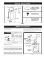
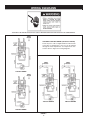
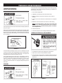
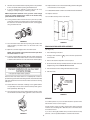
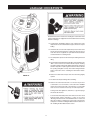
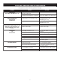
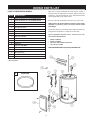
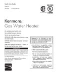
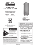
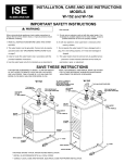
Instruction Manual
RESIDENTIAL POINT OF USE ELECTRIC
WATER HEATERS
FOR POTABLE WATER
HEATING ONLY
NOT SUITABLE FOR
SPACE HEATING
LISTED
GAMA certification applies to all
residential electric water heaters
with capacities of 20 to 120 gallons.
Input rating of 12 Kw or less.
ALL TECHNICAL AND WARRANTY QUESTIONS: SHOULD BE DIRECTED TO THE LOCAL DEALER FROM WHOM THE WATER HEATER WAS
PURCHASED. IF YOU ARE UNSUCCESSFUL, PLEASE WRITE TO THE COMPANY LISTED ON THE RATING PLATE ON THE WATER HEATER.
KEEP THIS MANUAL IN THE POCKET ON HEATER FOR FUTURE REFERENCE
WHEN EVER MAINTENANCE ADJUSTMENT OR SERVICE IS REQUIRED.
PRINTED IN THE U.S.A 0104
1
PART NO. 184735-000
SAFE INSTALLATION, USE AND SERVICE
Your safety and the safety of others is extremely important in the installation, use and servicing of this water heater.
Many safety-related messages and instructions have been provided in this manual and on your own water heater to warn you and
others of a potential injury hazard. Read and obey all safety messages and instructions throughout this manual. It is very
important that the meaning of each safety message is understood by you and others who install, use or service this water heater.
This is the safety alert symbol. It is used to alert you
to potential personal injury hazards. Obey all safety
messages that follow this symbol to avoid possible
injury or death.
DANGER
DANGER indicates an imminently
hazardous situation which, if not avoided,
could result in death or injury.
WARNING
WARNING indicates a potentially hazardous
situation which, if not avoided, could result
in death or injury.
CAUTION
CAUTION indicates a potentially hazardous
situation which, if not avoided, may result
in minor or moderate injury.
CAUTION
CAUTION used without the safety alert
symbol indicates a potentially hazardous
situation which, if not avoided, could result
in property damage.
All safety messages will generally tell you about the type of hazard, what can happen if you do not follow the safety message and
how to avoid the risk of injury.
IMPORTANT DEFINITIONS
•
Qualified Installer: A qualified installer must have ability equivalent to a licensed tradesman in the fields of plumbing, and electrical installation
of these appliances. This would include a thorough understanding of the requirements of the National Electrical Code and applicable local
electrical and plumbing codes (and tools necessary to confirm proper installation and operation of the water heater) as they relate to
the installation of electric water heaters. The qualified installer must have a thorough understanding of the water heater
Instruction Manual.
•
Service Agency: A service agency also must have ability equivalent to a licensed tradesman in the fields of plumbing, and electrical installation
of these appliances. This would include a thorough understanding of the requirements of the National Electrical Code and applicable local
electrical and plumbing codes (and tools necessary to confirm proper installation and operation of the water heater) as they relate to
the installation of electric water heaters. The service agency must have a thorough understanding of the water heater
Instruction Manual.
2
GENERAL SAFETY
3
INTRODUCTION
Thank You for purchasing this water heater. Properly installed and
maintained, it should give you years of trouble free service.
This application has been listed as complying with UL Standard for
safety UL174.
Abbreviations Found In This Instruction Manual:
2. The installation must conform with these instructions and the local
code authority having jurisdiction and the requirements of the power
company. In the absence of code requirements follow the current
edition of the NEC, National Electrical Code NFPA-70 which may be
ordered from: National Fire Protection Association, 1 Batterymarch
Park, Quincy, MA 02269.
•
ANSI - American National Standards Institute
•
ASME - American Society of Mechanical Engineers
•
GAMA - Gas Appliance Manufacturers Association
•
NEC - National Electrical Code
•
NFPA - National Fire Protection Association
•
UL - Underwriters Laboratories Inc.
3. If after reading this manual you have any questions or do not
understand any portion of the instructions, call the local utility or the
manufacturer whose name appears on the rating plate.
4. Carefully plan the place where you are going to put the water heater.
INSTALLATION OR SERVICE OF THIS WATER HEATER REQUIRES
ABILITY EQUIVALENT TO THAT OF A LICENSED TRADESMAN IN
THE FIELD INVOLVED. PLUMBING AND ELECTRICAL WORK ARE
REQUIRED.
PREPARING FOR THE INSTALLATION
1. Read the “General Safety” section of this manual first and then the
entire manual carefully. If you don’t follow the safety rules, the
water heater will not operate properly. It could cause DEATH,
SERIOUS BODILY INJURY AND/OR PROPERTY DAMAGE.
Examine the location to ensure the water heater complies with the
“Facts to Consider About the Location” section in this manual.
5. For California installation this water heater must be braced, anchored,
or strapped to avoid falling or moving during an earthquake. See
instructions for correct installation procedures. Instructions may be
obtained from California Office of the State Architect, 400 P Street,
Sacramento, CA 95814.
This manual contains instructions for the installation, operation, and
maintenance of the electric water heater. It also contains warnings
throughout the manual that you must read and be aware of. All
warnings and all instructions are essential to the proper operation of
the water heater and your safety. Since we cannot put everything
on the first few pages, READ THE ENTIRE MANUAL BEFORE
ATTEMPTING TO INSTALL OR OPERATE THE WATER HEATER.
6. Massachusetts Code requires this water heater to be installed in
accordance with Massachusetts 248-CMR 2.00: State Plumbing Code
and 248-CMR 5.00.
TABLE OF CONTENTS
SAFE INSTALLATION, USE AND SERVICE ..................... 2
FOR YOUR INFORMATION .............................................. 13
GENERAL SAFETY ............................................................. 3
Thermal Expansion .................................................. 13
INTRODUCTION ................................................................ 4
Strange Sounds .................................................... 13
Preparing for the Installation ..................................... 4
Operational Conditions ............................................ 13
TABLE OF CONTENTS ...................................................... 4
Smelly Water .......................................................... 13
TYPICAL INSTALLATION .................................................... 5
“Air” in Hot Water Faucets .................................... 13
MIXING VALVE USAGE ....................................................... 5
High Water Temperature Shut Off System .......... 13
LOCATING THE NEW WATER HEATER ........................... 6
PERIODIC MAINTENANCE ....................................... 14-16
Facts to Consider About Location ............................. 6
Temperature-Pressure Relief Valve Operation ..... 14
Insulation Blankets ..................................................... 6
Draining ..................................................................... 14
INSTALLING THE NEW WATER HEATER ..................... 6-9
Thermostat Removal/Replacement .................. 14,15
Optional Wall Mounting ........................................... 6,7
Water Piping ............................................................. 7,8
Element Cleaning/Replacement ....................... 15,16
Temperature-Pressure Relief Valve ...................... 8,9
Drain Valve Washer Replacement .......................... 16
Filling the Water Heater ........................................... 10
Service ....................................................................... 16
WIRING DIAGRAMS ......................................................... 10
LEAKAGE CHECKPOINTS .............................................. 17
WIRING ............................................................................. 11
TROUBLESHOOTING GUIDELINES .............................. 18
TEMPERATURE REGULATION ....................................... 12
REPAIR PARTS LIST ........................................................ 19
Temperature Adjustment ......................................... 12
WARRANTY .............................................................. INSERT
4
TYPICAL INSTALLATION
INSTALL SUITABLE DRAIN PANS
UNDER HEATERS TO PREVENT
DAMAGE DUE TO LEAKAGE.
REFER TO WATER HEATER
LOCATION ON PAGE 8.
INSTALL VACUUM RELIEF IN
COLD WATER INLET LINE AS
REQUIRED BY LOCAL CODES.
INSTALL THERMAL EXPANSION
TANK OR DEVICE IF WATER
HEATER IS INSTALLED IN A
CLOSED WATER SYSTEM.
FIGURE 1.
MIXING VALVE USAGE
Water (Potable) Heating: All models are considered suitable for
water (potable) heating only.
contractor. Consult a Qualified Installer or Service Agency. Follow
mixing valve manufacturer’s instructions for installation of the valves.
Before changing the factory setting on the thermostat, read the
“Temperature Regulation” section in this manual.
HOTTER WATER CAN SCALD:
Water heaters are intended to produce hot water. Water heated to a
temperature which will satisfy space heating, clothes washing, dish
washing, and other sanitizing needs can scald and permanently injure
you upon contact. Some people are more likely to be permanently
injured by hot water than others. These include the elderly, children, the
infirm, or physically/mentally handicapped. If anyone using hot water in
your home fits into one of these groups or if there is a local code or state
law requiring a certain temperature water at the hot water tap, then you
must take special precautions. In addition to using the lowest possible
temperature setting that satisfies your hot water needs, a means such
as a *mixing valve, shall be used at the hot water taps used by these
people or at the water heater. Mixing valves are available local plumbing
FIGURE 2.
5
LOCATING THE NEW WATER HEATER
damage to the structure. For this reason, it is not advisable to install the
water heater in an attic or upper floor. When such locations cannot be
avoided, a suitable drain pan should be installed under the water heater.
Drain pans are available from your local plumbing contractor. Such a
drain pan must have a minimum length and width of at least 2 inches
(51 mm) greater that the water heater dimensions and must be piped to
an adequate drain.
FACTS TO CONSIDER ABOUT THE LOCATION
Also, the water heater must be located and/or protected so it is not
subject to physical damage by a moving vehicle.
INSULATION BLANKETS
Carefully choose an indoor location for the new water heater, because
the placement is a very important consideration for the safety of the
occupants in the building and for the most economical use of the
appliance.
Whether replacing an old water heater or putting the water heater in a
new location, the following critical points must be observed:
Insulation blankets are available to the general public for external use
on electric water heaters but are not necessary with this product. The
purpose of an insulation blanket is to reduce the standby heat loss
encountered with storage tank heaters. Your water heater meets or
exceeds the National Appliance Energy Conversation Act standards
with respect to insulation and standby loss requirements, making an
insulation blanket unnecessary.
1. Select a location indoors as close as practical or centralized to the
water piping system as possible. The water heater should be
located in an area not subject to freezing temperatures.
Should you choose to apply an insulation blanket to this heater, you
should follow these instructions below. Failure to follow these
instructions can result in fire, serious personal injury, or death.
2. Selected location must provide adequate clearances (4”) for servicing
parts such as the thermostats, drain valve and relief valve. Adequate
clearance for servicing this appliance should be considered before
installation, such as changing the anodes, etc.
• Do not cover the temperature and pressure relief (T & P) valve with
an insulation blanket.
• Do not cover the instruction manual. Keep it on the side of the
water heater or nearby for future reference.
Installation of the water heater must be accomplished in such a manner
that if the tank or any connections should leak, the flow will not cause
• Do obtain new warning and instruction labels for placement on the
blanket directly over the existing labels.
INSTALLING THE NEW WATER HEATER
OPTIONAL WALL MOUNTING
WALL CONSTRUCTION AT THE POINT OF THE WATER HEATER
INSTALLATION MUST BE CAPABLE OF SUPPORTING AT LEAST 200
POUNDS.
As an example: if the water heater is to be installed on a wall of
gypsum board (dry wall) or other material not capable of supporting
the water heater filled with water, additional bracing will be necessary.
Two possibilities are shown, see Figure 3.
1. Using two sheet metal screws supplied, secure the top mounting
bracket to the top of the water heater.
FIGURE 4.
2. Using the remaining two sheet metal screws provided, secure the
bottom mounting bracket to the bottom of the water heater.
FIGURE 3.
6
HOTTER WATER CAN SCALD:
Water heaters are intended to produce hot water. Water heated to a
temperature which will satisfy space heating, clothes washing, dish
washing, cleaning and other sanitizing needs can scald and permanently
injure you upon contact. Some people are more likely to be permanently
injured by hot water than others. These include the elderly, children,
the infirm, or physically/mentally handicapped. If anyone using hot
water in your home fits into one of these groups or if there is a local
code or state law requiring a certain temperature water at the hot
water tap, then you must take special precautions. In addition to using
the lowest possible temperature setting that satisfies your hot water
needs, a means such as a *mixing valve, shall be used at the hot water
taps used by these people or at the water heater. Valves for reducing
point of use temperature by mixing cold and hot water are also available.
Consult a Qualified Installer or Service Agency. Follow manufacturer’s
instructions for installation of the valves. Before changing the factory
setting on the thermostat, read the “Temperature Regulation” section in
this manual.
FIGURE 5.
3. Determine the location on the wall, and then the height above the
floor which the wall securing bracket will be placed. Using adequate
screws, or nuts, and bolts (not supplied) fasten the wall securing
bracket to the wall.
This water heater shall not be connected to any heating systems or
component(s) used with a non-potable water heating appliance.
Toxic chemicals, such as those used for boiler treatment shall not be
introduced into this system.
Water supply systems may, because of such events as high line
pressure, frequent cut-offs, the effects of water hammer among
others, have installed devices such as pressure reducing valves, check
valves, back flow preventers, etc. to control these types of problems.
When these devices are not equipped with an internal by-pass, and no
other measures are taken, the devices cause the water system to be
closed. As water is heated, it expands (thermal expansion) and closed
systems do not allow for the expansion of heated water.
The water within the water heater tank expands as it is heated and
increases the pressure of the water system. If the relieving point of
the water heater’s temperature-pressure relief valve is reached, the
valve will relieve the excess pressure. The temperature-pressure
relief valve is not intended for the constant relief of thermal
expansion. This is an unacceptable condition and must be corrected.
It is recommended that any devices installed which could create a
closed system have a by-pass and/or the system have an expansion
tank or device to relieve the pressure built by thermal expansion in the
water system. Expansion tanks are available for ordering through a
local plumbing contractor. Contact the local water supplier and/or a
service agency for assistance in controlling these situations.
FIGURE 6.
WATER PIPING
NOTE: To protect against untimely corrosion of hot and cold
water fittings, it is strongly recommended that di-electric
unions or couplings be installed on this water heater when
connected to copper pipe.
7
If replaced, the valve must meet the requirements of local codes, but
not less than a combination temperature and pressure relief valve
certified as indicated in the above paragraph.
Figure 7 shows the typical attachment of the water piping to the water
heater. The water heater is equipped with 3/4 inch NPT water
connections.
The valve must be marked with a maximum set pressure not to exceed
the marked hydrostatic working pressure of the water heater
(150 psi = 1,035 kPa) and a discharge capacity not less than the water
heater input rate as shown on the model rating plate.
NOTE: If using copper tubing, solder tubing to an adapter
before attaching the adapter to the cold water inlet connection.
Do not solder the cold water supply line directly to the cold
water inlet, it will harm the dip tube and damage the tank.
For safe operation of the water heater, the relief valve must not be
removed from its designated opening nor plugged.
The temperature-pressure relief valve must be installed directly into
the fitting of the water heater designed for the relief valve. Position the
valve downward and provide tubing so that any discharge will exit
only within 6 inches (153 mm) above, or at any distance below the
structural floor. Be certain that no contact is made with any live electrical
part. The discharge opening must not be blocked or reduced in size
under any circumstances. Excessive length, over 30 feet (9.14 m), or
use of more than four elbows can cause restriction and reduce the
discharge capacity of the valve.
No valve or other obstruction is to be placed between the relief valve
and the tank. Do not connect tubing directly to discharge drain unless
a 6 inch air gap is provided. To prevent bodily injury, hazard to life, or
property damage, the relief valve must be allowed to discharge water
in quantities should circumstances demand. If the discharge pipe is not
connected to a drain or other suitable means, the water flow may
cause property damage.
FIGURE 7.
The Discharge Pipe:
TEMPERATURE-PRESSURE RELIEF VALVE
• Shall not be smaller in size than the outlet pipe size of the valve, or
have any reducing couplings or other restrictions.
• Shall not be plugged or blocked.
• Shall be of material listed for hot water distribution.
• Shall be installed so as to allow complete drainage of both the
temperature-pressure relief valve, and the discharge pipe.
• Shall terminate at an adequate drain.
• Shall not have any valve between the relief valve and tank.
This heater is provided with a properly certified combination
temperature - pressure relief valve by the manufacturer.
The valve is certified by a nationally recognized testing laboratory that
maintains periodic inspection of production of listed equipment of
materials as meeting the requirements for Relief Valves and Automatic
Gas Shut-off Devices for Hot Water Supply Systems, ANSI Z21.22 •
CSA 4.4, and the code requirements of ASME.
8
The temperature-pressure relief valve must be manually operated at
least once a year. Caution should be taken to ensure that (1) no one is
in front of or around the outlet of the temperature-pressure relief valve
discharge line, and (2) the water manually discharged will not cause
any bodily injury or property damage because the water may be
extremely hot.
If after manually operating the valve, it fails to completely reset and
continues to release water, immediately close the cold water inlet to
the water heater, follow the draining instructions, and replace the
temperature-pressure relief valve with a new one.
FILLING THE WATER HEATER
Never use this water heater unless it is completely full of water. To
prevent damage to the tank, the tank must be filled with water. Water
must flow from the hot water faucet before turning “ON” electrical
supply to the water heater.
To fill the water heater with water:
1. Close the water heater drain valve by turning the handle to the right
(clockwise). The drain valve is on the lower front of the water
heater.
2. Open the cold water supply valve to the water heater.
NOTE: The cold water supply valve must be left open when
the water heater is in use.
3. To insure complete filling of the tank, allow air to exit by opening the
nearest hot water faucet. Allow water to run until a constant flow
is obtained. This will let air out of the water heater and the piping.
FIGURE 8.
4. Check all water piping and connections for leaks. Repair as needed.
9
WIRING DIAGRAMS
TURN OFF THE HEATER ELECTRICAL SUPPLY BEFORE SERVICING ANY ELECTRICAL COMPONENTS.
OPTIONAL CORD SET WIRING (120 Volt and 240 Volt)
There may be a cord set supplied with the water heater
at the time of manufacture. If not one can be ordered
through the Parts Department; see “Repair Parts List”
section. Refer to Figure 9 for wiring diagrams.
120 VOLT WIRING
120 VOLT WIRING
240 VOLT WIRING
FIGURE 9.
10
240 VOLT WIRING
WIRING
1. Provide a way to easily shut off the electric power when working
on the water heater. This could be with a circuit breaker or fuse
block in the entrance box or a separate disconnect switch.
2. Install and connect a circuit directly from the main fuse or circuit
breaker box. This circuit must be the right size and have its own
fuse or circuit breaker.
3. If metal conduit is used for the grounding conductor:
A. The grounding electrode conductor shall be of copper, aluminum,
or copperclad aluminum. The material shall be of one continuous
length without a splice or joint.
Never use water heater unless it is completely full of water. To prevent
damage to the tank and heating element, the tank must be filled with
water. Water must flow from the hot water faucet before turning on
power.
B. Rigid metal conduit, intermediate metal conduit, or electrical,
metallic tubing may be used for the grounding means if conduit or
tubing is terminated in fittings approved for grounding.
You must provide all wiring of the proper size outside of the water
heater. You must obey local codes and electric company requirements
when you install this wiring.
C. Flexible metal conduit or flexible metallic tubing shall be permitted
for grounding if all the following conditions are met:
If you are not familiar with electric codes and practices, or if you have
any doubt in your ability to connect the wiring to this water heater,
obtain the service of a competent electrician. Contact a local electrical
contractor and/or the local electric utility.
•
The length in any ground return path does not exceed 6 feet.
•
The circuit conductors contained therein are protected by
overcurrent devices rated at 20 amperes or less.
•
The conduit or tubing is terminated in fittings approved for
grounding.
For complete grounding details and all allowable exceptions, refer to
the current edition of the NEC, National Electrical Code NFPA 70.
4. A standard 1/2” conduit opening has been made in the water heater
junction box for the conduit connections.
5. Use wire nuts and connect the power supply wiring to the wires
inside the water heater’s junction box.
6. The water heater must be electrically “grounded” by the installer. A
green ground screw has been provided on the water heater’s
junction box. Connect ground wire to this location.
7. Replace the wiring junction cover using the screw provided.
WATER HEATERS EQUIPPED FOR ONE VOLTAGE ONLY: This water
heater is equipped for one type voltage only. Check the rating plate
near the bottom access panel for the correct voltage. DO NOT use this
water heater with any voltage other than the one shown on the model
rating plate. Failure to use the correct voltage can cause problems
which can result in DEATH, SERIOUS BODILY INJURY, OR PROPERTY
DAMAGE. If you have any questions or doubts consult your electric
company.
If wiring from your fuse box or circuit breaker box was aluminum for
your old water heater, replace it with copper wire. If you wish to reuse
the existing aluminum wire, have the connection at the water heater
made by a competent electrician. Contact a local electrical contractor
and/or the local electric utility.
FIGURE 10.
11
TEMPERATURE REGULATION
Due to the nature of the typical water heater, the water temperature in
certain situations may vary up to 30°F (16.7 °C) higher or lower at the
point of use such as, bathtubs, showers, sink, etc.
TEMPERATURE ADJUSTMENT
Any water heater’s intended purpose is to heat water. Hot water is
needed for cleansing, cleaning, and sanitizing (bodies, dishes, clothing).
Untempered hot water can present a scald hazard. Depending on the
time element, and the people involved (adults, children, elderly, infirm,
etc.) scalding may occur at different temperatures.
To change the temperature setting:
NOTE:
1. Turn off the heater electrical supply. Do not attempt to adjust
thermostat with power on.
2. Remove the thermostat outer door and fold away the insulation
from the thermostat. Do not remove the plastic personnel protector
covering the thermostat.
HOTTER WATER CAN SCALD: Water heaters are intended to produce
hot water. Water heated to a temperature which will satisfy space
heating, clothes washing, dish washing, and other sanitizing needs
can scald and permanently injure you upon contact. Some people are
more likely to be permanently injured by hot water than others. These
include the elderly, children, the infirm, or physically/mentally
handicapped. If anyone using hot water in your home fits into one of
these groups or if there is a local code or state law requiring a certain
temperature water at the hot water tap, then you must take special
precautions. In addition to using the lowest possible temperature setting
that satisfies your hot water needs, a means such as a mixing valve,
shall be used at the hot water taps used by these people or at the
water heater. Mixing valves are available from your local plumbing
contractor. Follow manufacturer’s instructions for installation of the
valves. Before changing the factory setting on the thermostat, read
the “Temperature Regulation” section in this manual.
3. Using a flat tip screwdriver, rotate the adjustment knob to the desired
temperature setting.
4. Fold the insulation back in place, replace the outer door and turn on
heater electrical supply.
LO - Setting, approximately 95°F (35°C)
is recommended for vacations or
extended periods of no hot water.
THIS WATER HEATER IS EQUIPPED WITH AN ADJUSTABLE
THERMOSTAT TO CONTROL WATER TEMPERATURE. HOT
WATER TEMPERATURES DESIRED FOR AUTOMATIC
DISHWASHER AND LAUNDRY USE CAN CAUSE SCALDS RESULTING
IN SERIOUS PERSONAL INJURY AND/OR DEATH.
THE TEMPERATURE AT WHICH INJURY OCCURS VARIES WITH THE
PERSON’S AGE AND THE TIME OF THE EXPOSURE. THE SLOWER
RESPONSE TIME OF CHILDREN, AGED OR DISABLED PERSONS
INCREASES THE HAZARDS TO THEM. NEVER ALLOW SMALL
CHILDREN TO USE A HOT WATER TAP, OR TO DRAW THEIR OWN
BATH WATER. NEVER LEAVE A CHILD OR DISABLED PERSON
UNATTENDED IN A BATHTUB OR SHOWER.
HI - Is setting for the maximum hot water
usage approximately 140°F (60°C),
which can be supplied by the water
heater.
TEMPERATURE SETTINGS
It is recommended that lower water temperatures be used to avoid the
risk of scalding. It is further recommended, in all cases, that the water
temperature thermostat be set for the lowest temperature which
satisfies your hot water needs, see Figure 11. This will also provide
the most energy efficient operation of the water heater. The Thermostat
has been factory set between LO an HI which approximates 120°F
(49°C) unless specified differently by state requirements.
It is recommended that the dial be set lower whenever possible.
Temperature
Setting
160°F
150°F
140°F
130°F
120°F
KEEPING THE THERMOSTAT SETTING AT 120°F (49°C) WILL REDUCE
THE RISK OF SCALDS.
Figure 11 shows the approximate time-to-burn relationship for normal
adult skin.
(71°C)
(66°C)
(60°C)
(54°C)
(49°C)
Time to Produce 2nd & 3rd
Degree Burns on Adult Skin
About 1/2 second
About 1-1/2 seconds
Less than 5 seconds
About 30 seconds
More than 5 minutes
FIGURE 11.
12
FOR YOUR INFORMATION
bleach as needed. On systems where the odor is mild and does not
occur too rapidly, a monthly flushing may be sufficient. In more severe
cases, a system feeder would be more appropriate.
THERMAL EXPANSION
“AIR” IN HOT WATER FAUCETS
Water supply systems may, because of such events as high line
pressure, frequent cut-offs, the effects of water hammer among
others, have installed devices such as pressure reducing valves, check
valves, back flow preventers, etc. to control these types of problems.
When these devices are not equipped with an internal by-pass, and no
other measures are taken, the devices cause the water system to be
closed. As water is heated, it expands (thermal expansion) and closed
systems do not allow for the expansion of heated water.
HYDROGEN GAS: Hydrogen gas can be produced in a hot water
system that has not been used for a long period of time (generally two
weeks or more). Hydrogen gas is extremely flammable and explosive.
To prevent the possibility of injury under these conditions, we
recommend the hot water faucet, located farthest away, be opened
for several minutes before any electrical appliances which are
connected to the hot water system are used (such as a dishwasher or
washing machine). If hydrogen gas is present, there will probably be
an unusual sound similar to air escaping through the pipe as the hot
water faucet is opened. There must be no smoking or open flame near
the faucet at the time it is open.
The water within the water heater tank expands as it is heated and
increases the pressure of the water system. If the relieving point of
the water heater’s temperature-pressure relief valve is reached, the
valve will relieve the excess pressure. The temperature-pressure
relief valve is not intended for the constant relief of thermal
expansion. This is an unacceptable condition and must be corrected.
It is recommended that any devices installed which could create a
closed system have a by-pass and/or the system have an expansion
tank or device to relieve the pressure built by thermal expansion in the
water system. Expansion tanks are available for ordering through a
local plumbing contractor. Contact the local water heater supplier or
service agency for assistance in controlling these situations.
HIGH WATER TEMPERATURE SHUT OFF SYSTEM
A non-adjustable high temperature limit control operates before steam
temperatures are reached. The high limit is in the same area as the
thermostat and must be reset manually when it operates. BECAUSE
THE HIGH LIMIT OPERATES ONLY WHEN ABNORMALLY HIGH
WATER TEMPERATURES ARE PRESENT, IT IS IMPORTANT THAT A
QUALIFIED SERVICE AGENT BE CONTACTED TO DETERMINE
THE REASON FOR OPERATION BEFORE RESETTING.
STRANGE SOUNDS
Possible noises due to expansion and contraction of some metal parts
during periods of heat-up and cool-down do not necessarily represent
harmful or dangerous conditions.
OPERATIONAL CONDITIONS
SMELLY WATER
In each water heater there is installed at least one anode rod (see
parts sections) for corrosion protection of the tank. Certain water
conditions will cause a reaction between this rod and the water. The
most common complaint associated with the anode rod is one of a
“rotten egg smell” in the hot water. This odor is derived from hydrogen
sulfide gas dissolved in the water. The smell is the result of four
factors which must all be present for the odor to develop:
A. A concentration of sulfate in the supply water.
B. Little or no dissolved oxygen in the water.
C. A sulfate reducing bacteria which has accumulated within the water
heater (this harmless bacteria is nontoxic to humans).
D. An excess of active hydrogen in the tank. This is caused by the
corrosion protective action of the anode.
The anode rod in a new glass-lined water heater works rapidly to
protect the tank. After a period of time the anode action slows and the
odor may dissipate.
A smelly water condition (Rotten Egg Odor) in your Point of Use water
heater can , in most cases, be resolved or reduced with the addition of
sufficient amounts of chlorine to eliminate the bacterial growth inside
the tank. This can be accomplished through the installation of a chlorine
feeder to the system or the periodic flushing of the water heater with
13
•
Turn off the heater electrical supply. Do not attempt to reset thermostat
with power on.
•
Remove the two screws securing the outer door and remove door.
•
Fold back the insulation to expose the reset button opening.
•
Reset the high limit by pushing in the red button marked “RESET”.
•
Fold back the insulation so that it completely covers the thermostat
and element.
•
Replace the outer door.
•
Turn “ON” electric power to the water heater.
PERIODIC MAINTENANCE
TEMPERATURE-PRESSURE
RELIEF VALVE OPERATION
The water heater should be drained if being shut down during freezing
temperatures. Also periodic draining and cleaning of sediment from
the tank may be necessary.
1. Turn electrical supply “OFF”.
2. CLOSE the cold water inlet valve to the water heater.
3. OPEN a nearby hot water faucet and leave open to allow for
draining.
4. Connect a hose to the drain valve and terminate to an adequate
drain.
5. OPEN the water heater drain valve to allow for tank draining.
NOTE: If the water heater is going to be shut down and
drained for an extended period, the drain valve should be
left open with hose connected allowing water to terminate
to an adequate drain.
The temperature-pressure relief valve must be manually operated at
least once a year.
6. Close the drain valve.
When checking the temperature-pressure relief valve operation, make
sure that (1) no one is in front of or around the outlet of the temperaturepressure relief valve discharge line, and (2) that the water discharge
will not cause any property damage, as the water may be extremely
hot, see Figure 9.
7. Follow the instructions in the “Filling the Water Heater” section.
THERMOSTAT REMOVAL / REPLACEMENT
FIGURE 12.
If after manually operating the valve, it fails to completely reset and
continues to release water, immediately close the cold water inlet to
the water heater, follow the draining instructions, and replace the
temperature-pressure relief valve with a new one.
1. Turn “OFF” the electric power supply to the water heater.
2. Remove the outer door and fold back the insulation.
3. Lift out the tab as shown below to unclip the terminal cover from
the thermostat. The terminal cover can now be removed from the
thermostat.
If the temperature-pressure relief valve on the appliance weeps or
discharges periodically, this may be due to thermal expansion. You
may have a check valve installed in the water line or a water meter
with a check valve. Consult your local water supplier or service
agency for further information. Do not plug the temperature-pressure
relief valve.
DRAINING
FIGURE 13.
14
4.
Remove the two wires attached to the thermostat.
5.
Remove the thermostat from behind the thermostat bracket.
The water passing out of the drain valve may be extremely hot. To
avoid being scald, make sure all connections are tight and that the
water flow is directed away from any person.
6.
Disconnect wires from thermostat and slide out of the bracket.
4. Remove the two screws securing the outer door, and remove door.
7.
Place the new lower thermostat in the bracket making sure it fits
firmly against the tank.
8.
Attach the wires to the new thermostat.
NOTE: Some of the terminals may require straight-in wiring
through an eye-opening. If wires are now looped, recut
and strip wire 3/8” to a straight length and insert.
9.
FIGURE 16.
Put plastic terminal cover back in place.
5. Open the flap of insulation to expose the opening.
10. Fold back the insulation to cover the thermostat.
11. Replace outer door then turn the electric power on.
ELEMENT CLEANING / REPLACEMENT
FIGURE 17.
6. Lift out the tab as shown below to unclip the terminal cover from the
thermostat. The terminal cover can now be removed from the
thermostat.
To remove the element from the tank in order to clean or replace it:
1. Before beginning turn “OFF” the electric power supply to the water
heater.
2. Turn off the water supply to the water heater at the water shut-off
valve or water meter.
FIGURE 14.
3. Attach a hose to the water heater drain valve and put the other end
in a floor drain or outdoors. Open the water heater drain valve.
Open a nearby hot water faucet which will relieve pressure in the
water heater and speed draining.
FIGURE 18.
7. Disconnect the two wires on the element and unscrew the old
element from the tank.
FIGURE 15.
FIGURE 19.
15
8.
Clean the area around the element opening. Remove any sediment
from or around the element opening and inside the tank.
16. Replace terminal cover on thermostat making sure the locking tabs
on the terminal cover are in place.
9.
If you are cleaning the element you have removed, do so by
scraping or soaking in vinegar or a deliming solution.
17. Fold back the insulation so that it covers the thermostat and element.
18. Replace outer door.
NOTE: Replacement elements must (1) be the same voltage
and (2) no greater wattage than listed on the model rating
plate affixed to the water heater.
19. Turn “ON” electric power to water heater.
10. A new gasket should be used in all cases to prevent a possible
water leak. Place the new element gasket on the threaded side of
the cleaned or new element and screw into tank, securing tightly
using an element wrench.
FIGURE 20.
FIGURE 22.
11. Close the water heater drain valve by turning the handle to the
right (clockwise). The drain valve is on the lower front of the
water heater.
DRAIN VALVE WASHER REPLACEMENT
12. Open the cold water supply valve to the water heater.
(See Figure 23)
NOTE: The cold water supply valve must be left open when
the water heater is in use.
1. Follow “Draining” instructions.
2. Turning counter clockwise (
screw handle.
13. To insure complete filling of the tank, allow air to exit by opening the
nearest hot water faucet. Allow water to run until a constant flow
is obtained. This will let air out of the water heater and the piping.
), remove the hex cap below the
3. Remove the washer and put the new one in place.
4. Screw the handle and cap assembly back into the drain valve and
retighten using a wrench. DO NOT OVER TIGHTEN.
5. Follow instructions in the “Filling The Water Heater” section.
6. Check for leaks.
Never use this water heater unless it is completely full of water. To
prevent damage to the tank and heating element, the tank must be filled
with water. Water must flow from the hot water faucet before turning
“ON” power.
14. Check element for water leaks. If leakage occurs, tighten element
or repeat Steps 2 and 3, remove element and reposition gasket.
Then repeat Steps 10 through 14.
15. Reconnect the two wires to the element and then check to make
sure the thermostat remains firmly against the surface of the tank.
FIGURE 23.
SERVICE
If a condition persists or you are uncertain about the operation of the
water heater contact a service agency.
Use this guide to check a “Leaking” water heater. Many suspected
“Leakers” are not leaking tanks. Often the source of the water can be
found and corrected.
If you are not thoroughly familiar with your water heater and safety
practices, contact a qualified installer to check the water heater.
FIGURE 21.
16
LEAKAGE CHECKPOINTS
Read this manual first. Then before checking the water heater make
sure the electrical power supply has been turned “OFF” before checking
the tank for leakage.
*A. Condensation and dripping may be seen on pipes if the water
temperature is low in humid weather or pipe connections may be
leaking.
B. Small amounts of water from temperature-pressure relief valve
may be due to thermal expansion or high water pressure in your
area. If the valve is not piped to an open drain the released water
could be mistaken for a leaking heater.
*C. The temperature-pressure relief valve may be leaking at the tank
fitting.
E. The element may be leaking at the tank fitting. Turn electrical power
“OFF”, remove outer door, insulation block and pad. If leaking
around the element, follow proper draining instructions and remove
element. Reposition or replace gasket on element. Place element
into opening and tighten securely. Then follow “Filling the Water
Heater” instructions in the “Installing the New Water Heater”
section.
E. Water from a drain valve may be due to the valve being slightly
opened.
FIGURE 24.
*F. The drain valve may be leaking at the tank fitting.
*G. Water in the water heater bottom or on the floor may be from
condensation, loose connections, or the relief valve. DO NOT
replace the water heater until a full inspection of all possible
water sources is made and necessary corrective steps taken.
Leakage from other appliances, water lines, or ground seepage
should also be checked.
*
17
To check where threaded portion enters tank, insert cotton swab
between jacket opening and fitting. If cotton is wet, follow
“Draining” instructions in the “Periodic Maintenance” section and
then remove fitting. Put pipe dope or teflon tape on the threads
and replace. Then follow “Filling the Water Heater” instructions in
the “Installing the New Water Heater” section.
TROUBLESHOOTING GUIDELINES
These guidelines should be utilized by a qualified service agent.
Problem
Cause
WATER LEAKS
(See Leakage Checkpoints on 17)
Improperly sealed, hot or cold supply connection,
relief valve or drain valve.
Tighten threaded connections.
Leakage from other appliances or water lines.
Inspect other appliances near water heater.
Thermal expansion in closed water system.
Install thermal expansion tank
(DO NOT plug T&P valve).
Improperly seated valve.
Check relief valve for proper operation
(DO NOT plug T&P valve).
High sulfate or mineral content in water supply.
Drain and flush heater thoroughly, then refill.
Bacteria in water supply.
Chlorinate water supply.
Power supply to heater is not on.
Turn disconnect switch on or contact
electrician.
Thermostat set too low.
Refer to temperature regulation.
Heater undersized.
Reduce hot water use.
Incoming water is usually cold (Winter).
Allow more time for heat to reheat.
Leaking hot water from pipes or fixtures.
Have plumber check and repair leaks.
High temperature limit switch activated.
Contact dealer to determine cause. See
temperature regulation.
Thermostat set too high.
Refer to temperature regulation.
High temperature limit switch activated.
Contact dealer to determine cause. See
temperature regulation.
Scale accumulation on element.
Contact dealer to clean or replace element.
Sediment build-up on tank bottom.
Drain and flush thoroughly, then refill.
LEAKING TEMPERATURE
AND PRESSURE
RELIEF VALVE
HOT WATER ODORS
(CAUTION: UNAUTHORIZED REMOVAL OF THE
ANODE(S) WILL VOID THE WARRANTY FOR
FURTHER INFORMATION, CONTACT YOUR
DEALER)
NOT ENOUGH
OR
NO HOT WATER
HOT WATER TOO HOT
WATER HEATER SOUNDS
18
Solution
REPAIR PARTS LIST
Now that you have purchased this water heater, should a
need ever exist for repair parts or service, simply contact the
company it was purchased from or the manufacturer listed
on the rating plate on the water heater.
POINT OF USE ELECTRIC MODELS
Key No.
Part Description
1
Cord Set 120 Volt for use w/1440W element
2
Cord Set 240 Volt for use w/1500W element
Be sure to provide all pertinent facts when you call or visit.
3
Thermostat w/Hi-Limit*
4
Access Panel
5
Thermostat Cover
Selling prices will be furnished on request or parts will be
shipped at prevailing prices and you will be billed
accordingly.
6
Drain Valve
7
Junction Box Cover
8
Temperature -Pressure Relief Valve
9
Dip Tube & Gasket
10
Element Gasket
11
Thermostat Bracket
12
Elements
The model number of your Water Heater will be found on the
rating plate located above or adjacent to outer door.
WHEN ORDERING REPAIR PARTS, ALWAYS GIVE THE
FOLLOWING INFORMATION:
•
•
•
•
120 Volt / 1440 Watts
240 Volt / 1500 Watts
13
Mounting Bracket
14
Wiring Bushing
15
Drain Pan w/Side Drain
**
THIS IS A REPAIR PARTS LIST, NOT A PACKING LIST.
Instruction Manual
* NOTE: Special Point of Use thermostat only.
** Not Illustrated
15
MODEL NUMBER
SERIAL NUMBER
VOLTAGE AND ELEMENT WATTAGE
PART DESCRIPTION
DRAIN PAN
19
20