1
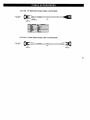
TM
LFI-3500 Series
Temperature Controllers
User’s Guide
2
LFI-3500 Series
Temperature Controller
User’s Guide
Publication number 92-130002D
© Copyright 1996, 1997, Wavelength Electronics, Inc.
P O Box 865, Bozeman, MT 59771
All Rights Reserved
Printed in U. S. A.
3
Thermoelectric Temperature Controllers
The 3500 series advanced design offers an unprecedented combination of features,
performance, and value. A variety of sensors including thermistors, IC sensors (AD590
and LM335), and RTDs are supported. A versatile I/O analog interface is provided at no
additional cost. Connect a standard 12 V fan to the 3500 series and cool your TE's
heatsink.
The fast PID control circuitry provides low noise, stable performance for even the most
stringent temperature control situations. With four proportional gains, two integral time
constants, and an optional derivative time constant, the PI/PID control loop can stabilize
virtually any load. The 3500 series utilizes Wavelength's "Smart Integrator" circuit to
reduce overshoot and improve settling time.
Extensive protection features are incorporated into the 3500 series to protect your
thermoelectric and temperature controlled device from damage. Easy to read LEDs
indicate temperature limit, open thermoelectric, and sensor open/short conditions.
Temperature and current limits are readily adjustable from front panel trimpots. For
additional safety, use the analog interface to disable an LFI-4500's laser diode driver
output if the temperature controller output is turned off for any reason.
Interlock any combination of LFI-3500 series temperature controllers or LFI-4500 series
laser diode drivers without additional hardware. Two or more modules mount into a 19"
rack with optional rack mount kits.
KEY FEATURES...
•
•
•
•
•
•
Ultra stable temperature control (< 0.002 °C)
Compatible with Thermistors, AD590, LM335, and RTDs
Four models deliver 15, 22, 25, and 40 W
Wide temperature control range from − 60°C to > +150°C
Easy to adjust operating temperature and current limit
Linear, low noise, bipolar current source
...THE WAVELENGTH ADVANTAGE
Low cost, flexible instrument
Fast PID control with "Smart Integrator" overshoot suppression
Adjustable "LOW" or "HIGH" temperature limit protection
Auxiliary thermistor monitors heatsink or ambient temperature
Connect an external fan and cool your TE's heatsink
Display thermoelectric voltage and current
Interlocking enclosures for complete laser drive solutions
Comprehensive Analog Interface includes:
TE V, TE I, TEMP SET, and ACTUAL TEMP outputs
Remote output ON/OFF control
External control of operating temperature
"Open Drain" ON/OFF and error status outputs
Directly integrates with LFI-4500 series laser diode drivers
Booster signal can drive higher powered amplifiers
4
LFI 3500 Series Selection Guide
Model
Description
LFI-3525
15 W, 2.5 Amp, 6 Volt, Temperature Controller
LFI-3526
22 W, 2.5 Amp, 9 Volt, Temperature Controller
LFI-3550
25 W, 5.0 Amp, 5 Volt, Temperature Controller
LFI-3551
40 W, 5.0 Amp, 8 Volt, Temperature Controller
Each model includes: 9&15 pin D-sub receptacles with shielded covers and hardware, user guide,
and AC power cord.
Cable - Selection Guide
Model
Description
Output cable, single connector (9 pin D-sub rec)
CAT-204
One end connectorized one end
unterminated
CAT-205
Output cable, double connector (9 pin D-sub rec's)
Both ends connectorized
All cables are 1 meter long.
Rack Mount Kits- Selection Guide
Model
Description
Rack mount kit for two LFI modules
RMK-502
Includes two
5 1/4" panels
RMK-503
Rack mount kit for three LFI modules
Includes one
1" panel and one
5 1/4" panel
RMK-504
Rack mount kit for four LFI modules
Includes two
1" panels
All RMK kits include (4)- 1/4-20 screws. No additional hardware is required to
attach rack mount brackets to LFI modules.
Thermistor Selection Guide
MODEL
R @ 25°°C
TCS-602
2.252 kΩ
Ω
TCS-605
5 kΩ
Ω
TCS-610
10 kΩ
Ω
TCS-620
20 kΩ
Ω
TCS-650
50 kΩ
Ω
TCS-651
100 kΩ
Ω
10 µA RANGE
− 60°° C
− 55°° C
− 45°° C
− 35°° C
− 18°° C
− 6°° C
to
to
to
to
to
to
− 12°° C
− 2°° C
+13°° C
+28°° C
+49°° C
+67°° C
100 µA RANGE
− 33°° C
− 20°° C
− 8°° C
+6°° C
+25°° C
+41°° C
to
to
to
to
to
to
+15°° C
+33°° C
+50°° C
+69°° C
+92°° C
+114°° C
5
Default Configuration from the Factory
The following are the factory default settings.
Rear Panel:
CONFIGURATION SWITCH:
OFF
1 2 3 4 5 6 7 8 9 10
ON
CONFIGURATION
Sensor setting: Thermistor, 100µA reference current
Loop Direction: NTC, for thermistors
PID Constants: P = 32, I = 1 second, D = OFF
Temperature Limit = HIGH
Front Panel:
LIMITS:
Temperature Limit: set at 7.72kΩ
(7.72kΩ corresponds to 30°C for a TCS-610 10kΩ thermistor)
Current Limit:
6
500 mA for LFI-3525 & LFI-3526
1 Amp for LFI-3550 & LFI-3551
TABLE OF CONTENTS
Default Configuration from the Factory ___________ 6
Safety Summary ______________________________ 8
Front Panel At a Glance _______________________ 10
Rear Panel At a Glance _______________________ 12
Preparing the Temperature Controller for Use_____ 15
Operating Guidelines _________________________ 16
Operation with Thermistors __________________ 16
Operation with the AD590____________________ 18
Operation with the LM335____________________ 20
Operation with RTDs________________________ 22
Set the Thermoelectric Current Limit __________ 25
Set the Temperature Limit ___________________ 26
Further Information___________________________ 28
Configure the PID Constants _________________ 28
Practical PID Setups ________________________ 30
Error and Status Indicators __________________ 31
Analog Interface ___________________________ 32
General Specifications ______________________ 34
Electrical Specifications _____________________ 35
Mechanical Specifications ___________________ 36
Cable Accessories__________________________ 37
Warranty ___________________________________ 38
7
Safety Summary
Do not install substitute parts or perform any unauthorized modification to the
product. Return the product to Wavelength Electronics for service and repair
to ensure that safety features are maintained.
Do not use this product beyond its specifications.
SYMBOL
DEFINITION OF SYMBOL
WARNING
Calls attention to a procedure, practice, or condition that could
possibly cause bodily injury or death.
!
ATTENTION
Ce symbole signale une procédure ou des conditions
dangereuses pouvant entraîner des blessures corporelles ou la
mort.
VORSICHT!
Nichtbeachtung der Hinweise können die körperliche
Unversehrtheit beeinträchtigen oder zum Tod führen.
NOTE!
Calls attention to a procedure, practice, or condition that could
possibly cause damage to equipment or devices being
operated by this equipment.
CAUTION Risk of Electric Shock
ATTENTION Risque d’Electrocution
VORSICHT Hochspannung
Earth Ground Symbol
Chassis Ground Symbol
8
NOTE!
Complete all operational steps in the order provided. Skipping
a step can result in damage to the device being controlled or
the Thermoelectric Module. Start with the section appropriate
to the type of sensor you are using
WARNING
For continued protection against fire, replace line fuse only with
fuse specified, type and rating.
!
ATTENTION
Pour une protection permanente contre les risques d’incendie,
ne remplacer les fusibles secteur que par des fusibles
conformes aux spécifications.
VORSICHT
Defekte Sicherungen sind nur durch die angegeben Typen und
mit den spezifizierten Werten zu ersetzen um die Sicherheit des
Gerätes zu gewährleisten.
CAUTION
RISK OF ELECTRICAL SHOCK. Do not power on this
instrument if the case is damaged or any of the covers or
panels are removed.
NO USER SERVICEABLE PARTS
INSIDE.
ATTENTION
Risque d’Electrocution. Ne pas mettre sous tension cet
instrument si le boîtier est endommagé ou si les capots ou les
faces sont retirés. Aucun composant réparable par l’utilisateur.
VORSICHT
Hochspannung.
Im Falle eines Gerätedefektes oder bei
geöffneter Verkleidung Netzstecker ziehen! Gerät kann und
braucht vom Anwender nicht gewartet werden.
CAUTION
POSSIBLE ELECTRICAL SHOCK OR FIRE HAZARD. Do not
expose the LFI Temperature Controller to rain or moisture. Do
not operate this instrument in the presence of flammable gases
or fumes.
ATTENTION
Risque d’électrocution ou d’incendie.
Ne pas exposer
l’alimentation LFI à la pluie ou à l’humidité. Ne pas utiliser cet
instrument en présence de gaz inflammable ou de fumée.
VORSICHT
Brandgefahr und Gefahr eines elektrischen Schocks! Setzen
Sie das Gerät nicht dem Regen oder der Feuchtigkeit aus.
Schalten Sie das Gerät in der Gegenwart entflammbarer Gase
oder Dämpfe nicht ein!
9
Temp Limit LED: This LED lights red whenever the load temperature exceeds the
limit temperature set by the Temp Limit Trimpot. The output current is switched off
when this error occurs.
Temp Limit Trimpot: This adjusts the Temp Limit Setpoint.
Sensor Error LED: This LED lights red whenever the sensor voltage is either
greater than 5V or less than 0.2V. This refers only to the feedback sensor, not the
auxiliary sensor. This condition can occur if the impedance of the sensor is too
high or too low, or if the sensor is disconnected from the Output Connector. The
output current is automatically switched off when this error occurs.
Output Section:
Output Enable Button:
This button enables and disables the thermoelectric
current source output. When the output is enabled, the current is determined by
the load conditions. If the output is disabled, the output current is brought to a very
low standby current. If an error occurs that shuts off the output, the button must be
pressed once to clear the error and again to enable the current.
Output On LED: This LED lights green whenever the output is enabled and current
flows through the TE module.
Adjust Potentiometer: This ten-turn linear potentiometer is provided to adjust the
Temperature Setpoint. It can adjust beyond the displayed temperature. See
page 33 (Pins 14 & 15 on the Analog Interface Connector -Temperature Monitor)
for more information.
Limit Current LED: This LED lights red whenever the output thermoelectric current
is limited to the adjustment set by the Limit Current Trimpot. This condition will
remain until the current required to achieve temperature falls below the Limit
Current Trimpot setting. This condition does not create an error to shut the output
off.
Limit Current Trimpot: This trimpot adjusts the thermoelectric Limit Current
Setpoint. Adjusting the trimpot clockwise increases the Limit Current.
Beeper: A single “beep” indicates when the output is turned on or off.
Display Section:
3 ½ Digit Display: This can be used to display the actual sensor temperature,
setpoint temperature, auxiliary zone temperature, output thermoelectric current,
thermoelectric limit current, and output thermoelectric voltage.
Display Select Switch: The position of this switch determines what value is
displayed on the 3 ½ digit LED display.
100µ
µA, 10µ
µA, and LINEAR: To display the resistance or temperature of the
sensor, the switch is set to one of these three positions. The first two positions
are for thermistors and RTDs. The switch position should be coordinated with
the reference current setting on the Configuration Switch on the rear panel.
The third position (LINEAR) is used for IC Sensors such as the LM335 or
AD590. To read the auxiliary sensor resistance, set the position to 100µ
µA and
hold in the Aux Sensor Button. To display the setpoint, set the position to the
one appropriate to the sensor being used and hold in the Display Set Button.
TE I: This position displays the amount of current being sourced through the
thermoelectric.
LIMIT I: This position displays the Limit Current Setpoint as set by the Limit
Current Trimpot.
TE V: This position displays the voltage across the thermoelectric.
11
Configuration Switch Bank:
This ten position switch bank configures the type of
sensor used, the feedback P, I, and D terms, and sets the
temperature limit to a HIGH or LOW limit.
OFF
1 2 3 4 5 6 7 8 9 10
ON
CONFIGURATION
Switches 1, 2, & 3: (10µA, 100µA, and 1000µA)
Determines reference current through the sensor. If more than one switch is ON, the
current will be the sum of the respective currents. These switches should always be
in the OFF position for AD590 sensors.
Switch Position
1
2
3
Reference Current
10µA
100µA
1000µA (1mA)
Switch 4: (AD590) In the ON position, this switch connects a 10kΩ resistance between
pin 5 (Sensor 1+) and pin 4 (Sensor -) on the output connector. This resistance will
create a voltage proportional to the current supplied by the AD590 sensor. This
should be in the OFF position for any other sensors.
Switch 5: (NTC/PTC) This switch determines loop polarity. Since a thermistor is a
negative temperature coefficient (NTC) sensor, the switch should be in the OFF
position when using a thermistor. The use of a PTC sensor, such as the LM335,
AD590, or RTD requires that this switch be in the ON position.
Switch 6: (Integral Term) This switch configures the integral time constant to be either
one or ten seconds. In the OFF position, the integral time constant is one second. In
the ON position, it is 10 seconds. The larger time constant should be selected for
those loads that cannot be stabilized using the one second time constant. See page
Error! Bookmark not defined. for a discussion of the P, I, and D terms.
Switches 7 & 8: (Proportional Term) Four gain choices are available- 16, 32, 64, and
84. The following table applies:
Gain
16
32
64
84
Switch 7
OFF
ON
OFF
ON
Switch 8
OFF
OFF
ON
ON
Switch 9: (Derivative Term) The LFI can operate as a PID or PI controller. In the OFF
position, the derivative term is removed. In the ON position, a differential time
constant of 250 milliseconds is used. The D term should be selected for large or hard
to stabilize loads.
Switch 10: (Temp Limit HIGH / LOW) The LFI can trigger an error to shut off the
output if the sensor temperature exceeds a HIGH temperature or falls below a LOW
temperature. The function of this switch changes depending on the type of sensor
used. The following table applies:
Temp Limit
LOW
HIGH
Sensor Type
NTC
ON
OFF
PTC
OFF
ON
Analog Interface Connector:
ANALOG
INPUT
50 Ω Terminator
1
8
9
15
BNC & 15 pin D-sub plug
ANALOG INTERFACE
Pins 1 & 2: (Mod+, Mod-) External analog input. The BNC input
is in parallel, but isolated by two 1kΩ resistors. Either of the
inputs can be used, but not simultaneously.
Pins 3 & 4: (Boost+, Boost-) Booster output.
Pins 5 & 6: (Err+, Err-) Connect to LFI-4500 laser diode drivers.
Pin 7: (Error Detect) Error status.
Pin 8: (On/Off Detect) On/Off status.
Pin 9: (Common) Common for pins 7, 8, & 10.
Pin 10: (Remote On/Off) Remote On/Off control.
Pin 11: (TE V) TE voltage monitor.
Pin 12: (TE I) TE current monitor.
Pin 13: (SET TEMP) Setpoint temperature monitor.
Pin 14: (ACT TEMP) Actual temperature monitor.
Pin 15: (Monitor Common) Common for pins 11-14.
14
Preparing the Temperature Controller for Use
Check the list of supplied items:
o One Power cord
o One 9 pin D-Sub receptacle (solder cup), hood, and connecting
hardware
o One 15 pin D-Sub receptacle (solder cup), hood, and connecting
o
o
þ
hardware
One AC Fuse installed
One AC Fuse is shipped separately.
This User’s Guide
Verify that the correct power-line fuse is installed and
the power-line voltage setting is correct.
The factory sets the following defaults based on the country of
destination for initial shipment:
Destination
Voltage Setting
Fuse Rating
US, Canada
UK
Continental Europe
Japan
115V
230V
230V
115V
2A
1A
1A
2A
For operation between 100 and 120VAC, install a 2 Amp slo-blow
5 x 20 mm fuse. Set the Voltage Select Switch to 115.
For operation between 220 and 240V operation, install a 1 Amp
slo-blow 5 x 20 mm fuse. Set the Voltage Select Switch to 230.
15
Step 4: Select the PID Constants
The most common PID settings for the AD590 are:
P - Gain = 64
I - Integral Time Constant = 10 seconds
D - Differential Time Constant = NONE
For more detailed PID setup, see page 28.
Step 5: Set the HIGH or LOW Temperature Limit
See page 26 for this operation detail.
Step 6: Adjust the LIMIT Current
See page 25 for this operation detail.
Step 7: Adjust the Temperature Setpoint
Rotate the Display Select Switch to the LINEAR position. The value displayed will be
the ambient temperature in Kelvin.
LINEAR IC Sensor Display Setting
Press and hold the Display Set Button. Rotate the Adjust Potentiometer until the
desired setpoint temperature is displayed.
Step 8: Enable the Output Current
Press and release the Output On Button. The Output On LED will light green. For a
small load, the Limit Current LED will briefly light red. More current is required to
initially change the load temperature than to maintain it once it is cool.
OUTPUT
ON
BEEP
19
Step 5: Set the HIGH or LOW Temperature Limit
See page 26 for this operation detail.
Step 6: Adjust the LIMIT Current
See page 25 for this operation detail.
Step 7: Adjust the Temperature Setpoint
Rotate the Display Select Switch to the LINEAR. The value displayed will be the
ambient temperature in Kelvin.
LINEAR IC Sensor Display Setting
Press and hold the Display Set Button. Rotate the Adjust Potentiometer until the
desired setpoint temperature is displayed.
Step 8: Enable the Output Current
Press and release the Output On Button. The Output On LED will light green. For a
small load, the Limit Current LED will briefly light red. More current is required to
initially change the load temperature than to maintain it once it is cool.
OUTPUT
ON
BEEP
21
Step 5: Set the HIGH or LOW Temperature Limit
See page 26 for this operation detail.
Step 6: Adjust the LIMIT Current
See page 25 for this operation detail.
Step 7: Adjust the Temperature Setpoint
Rotate the Display Select Switch to either the 10µA or 100µA position. The value
displayed will be the resistance of the RTD at ambient temperature. NOTE: Ignore
the decimal point on the 3½ digit display and the resistance of the RTD is
indicated in ohms.
RTD Display Setting
Press and hold the Display Set Button. Rotate the Adjust Potentiometer until the
desired setpoint resistance is displayed.
Step 8: Enable the Output Current
Press and release the Output On Button. The Output On LED will light green. For a
small load, the Limit Current LED will briefly light red. More current is required to
initially change the load temperature than to maintain it once it is cool.
OUTPUT
ON
BEEP
23
24
Configure the PID Constants
Switch 8
Switch 7
P
Switch 6
Setpoint +
Mod. Input
I
Sensor
Feedback
To Output
Power
Amplifier
Error Term
Switch 9
Error Amplifier
D
PID Processor
ERROR AMPLIFIER: The error amplifier section provides the difference
between the setpoint temperature and the actual temperature of the load
device as sensed by the temperature sensor. This difference is known as
the error term. This error term is fed to the PID processor. The range of the
setpoint temperature signal and the gain of the temperature sensor amplifier
typically determines the temperature range of the controller for a given
sensor.
The sensitivity of the error amplifier is determined by the temperature sensor
amplifier gain and the sensitivity of the temperature sensor. For example,
the error terms generated when using a 10kΩ thermistor and an AD590 at 15
°C are quite different. With a thermistor current source of 100µA, the
thermistor will produce a 76 mV/°C variation on the error term. The AD590
with a 10kΩ sense resistor will change the error term by 10 mV/°C. The
AD590 will allow you to operate over a wider temperature range than the
thermistor, but the thermistor will be more sensitive to temperature changes.
PID PROCESSOR: The PID processor section consists of a proportional
gain amplifier, an integrator, and a differentiator, all of which can be
implemented using simple op-amp circuits. In most PID controllers, the
integrator time constant (I) and differentiator time constant (D) are fixed and
only the proportional gain (P) is variable. Often, (D) is not even used, even
though it is necessary for an optimal system.
Simpler control loops utilize only the proportional gain stage. Proportional
controllers are inherently stable for low gains, but cannot produce a zero
error between the temperature setpoint and sensor feedback. A non-zero
error must be maintained to produce a finite output control signal. The
addition of the integrator function reduces the error to zero, but also reduces
the stability of the control loop. The integrator produces a finite output even
when the error term is zero because the output of the integrator is a function
28
Practical PID Setups:
Definitions:
Small Thermal Load: Qc < 5 Watts
Medium Thermal Load: 5 W < Qc < 20 Watts
Large Thermal Load: Qc > 20 Watts
Qc is the heat pumped from the TE’s cold surface.
Typical Settings for Thermistors
OFF
Small Thermal Load
1 2 3 4 5 6 7 8 9 10
P = 16, I = 1 sec, D = none
ON
OFF
Medium Thermal Load
1 2 3 4 5 6 7 8 9 10
P = 32, I = 1 sec, D = none
ON
OFF
Large Thermal Load
(cooling below ambient)
1 2 3 4 5 6 7 8 9 10
P = 32, I = 10 sec, D = none
ON
OFF
Large Thermal Load
(heating above ambient)
1 2 3 4 5 6 7 8 9 10
P = 64, I = 10 sec,
D = 250 msec
ON
Typical Settings for AD590 & LM335
OFF
Small Thermal Load
1 2 3 4 5 6 7 8 9 10
P = 32, I = 1 sec, D = none
ON
OFF
Medium Thermal Load
1 2 3 4 5 6 7 8 9 10
P = 64, I = 10 sec, D = none
ON
OFF
Large Thermal Load
1 2 3 4 5 6 7 8 9 10
P = 64, I = 10 sec,
D = 250 msec
ON
Typical Settings for RTDs
OFF
Small Thermal Load
1 2 3 4 5 6 7 8 9 10
P = 32, I = 10 sec,
D = 250 msec
ON
OFF
Medium Thermal Load
1 2 3 4 5 6 7 8 9 10
P = 64, I = 10 sec,
D = 250 msec
ON
OFF
Large Thermal Load
1 2 3 4 5 6 7 8 9 10
P = 84, I = 10 sec,
D = 250 msec
ON
These are recommended setups. Please consult Wavelength’s
Technical Note #201 for further examination of this topic.
30
Error and Status Indicators
Several LED indicators and a beeper are used to determine the status of the
controller.
Status Section
Power LED: This LED lights green whenever the AC Power Switch on the
front panel is depressed and AC power is supplied to the unit.
Temp Limit LED: This LED lights red whenever the load temperature
exceeds the Limit Temperature as set by the Temperature Limit Trimpot (see
page 26). The limit can be configured to trigger on a HIGH or LOW limit via
the configuration switch on the rear panel.
The output current is
automatically switched off when a Temp Limit condition occurs. Once the
error is corrected, the Output On Button must be pressed once to clear the
error and again to enable the output.
Open TE LED: This LED lights red whenever the voltage measured across
the thermoelectric module exceeds the compliance voltage of the LFI
controller. This condition can occur if the impedance of the thermoelectric is
too high for the amount of current being sourced through the device or if
there is no thermoelectric connected to the output connector. This condition
does not shut down the output current, and is only used to indicate a
possible output connection problem.
Sensor Error LED: This LED lights red whenever the main sensor voltage is
either greater than 5 V or less than 0.2 V. This condition can occur if the
impedance of the sensor is too high or too low for the sensing circuit, or if the
sensor is accidentally disconnected from the output connector. The output
current is automatically switched off when a Sensor Error condition occurs.
Once the error is corrected, the Output On Button must be pressed once to
clear the error and again to enable the output.
Output Section
On LED: This LED lights green whenever the Output On Button is toggled
on. This LED indicates that the output is now active and current will flow
through the output connector.
Limit LED: This LED lights red whenever the output thermoelectric current
is limited to the adjustment setting on the Limit Current Trimpot (see page
25). The output current will remain in this condition until the current required
to maintain temperature falls below the Limit Current Trimpot setting. This
condition does not switch the output current off.
Beeper: The LFI beeps once whenever the output is turned on or off.
31
Analog Interface
Pins 1 & 2: (Mod+, Mod-) An external analog signal can be directly connected to
these pins (or the Analog BNC Input) to remotely control temperature setpoint.
This input is configured to accept ± 10 V signals while withstanding inputs as
large as ± 40V. Any input on these pins is directly summed with the temperature
setpoint determined by the Adjust Potentiometer. Pins 1 & 2 are isolated from
the BNC Connector via 1kΩ resistors. This is to protect from accidentally
connecting two separate modulation input sources in parallel. The impedance of
this input is 60kΩ as measured across these terminals. A total of 30kΩ isolates
these inputs from pins 4 (Sensor -) and 7 (Fan Ground) on the Output
Connector. See the Transfer Function Table on page 33 for analog input
transfer functions.
NOTE!
If the thermistor or thermoelectric is earth
grounded - only the Analog Input BNC may
be used for remote control.
The shield side of the Analog BNC input is chassis grounded. Depending on
how the thermistor or thermoelectric is grounded, three options are available:
1. If the analog inputs are not used, install the 50 Ω terminator (provided with the unit)
on the BNC input.
2. If the thermistor or thermoelectric is not earth grounded, remove the 50 Ω BNC
terminator. The signal can be input through either the Analog Input BNC or the
Analog Interface Connector.
3. Only the Analog Input BNC may be used for controlling the temperature when
the thermistor or thermoelectric is earth grounded. Remove the 50 Ω BNC
terminator and replace it with the external modulation source.
Pins 3 , 4, & 15: (Boost+, Boost-, Monitor Common) These pins provide true
differential buffered outputs that can be used to drive an external power amplifier
to “boost” the power output of the controller. In this case, the thermoelectric is
connected to the booster power amplifier while the LFI controller provides the
PID temperature control. This signal is extracted from the PID section before the
current limit section. Either BOOSTER + or BOOSTER - can be referenced to
the MONITOR COMMON to provide the proper polarity to the external amplifier
for correct current flow through the thermoelectric. If BOOSTER + and
BOOSTER - are directly connected to the external amplifier, the amplifier’s gain
must be reduced by a factor of two since BOOSTER - is the complement of
BOOSTER +. Thermoelectric current and voltage must be monitored using the
external power amplifier electronics.
Pins 5 & 6: (Error+, Error-) These outputs were designed to connect to the
LFI-4500 series laser diode drivers. Complementary inputs on the laser diode
drivers are located on the LFI-4500 analog interface connector. Any LFI-4500
laser diode driver connected via these error lines will be disabled if the
temperature controller output is turned off for any reason (Output On Button or
Error shutoff). These outputs can source a maximum of 10 mA of current and a
total of three LFI-4500 laser diode drivers can be connected at one time.
NOTE!
LFI-4500’s output will NOT be disabled if
the LFI-3500 is in its powered off state
via its AC Power Switch.
Pins 7 & 9: (Error Detect, Common) This output is an open drain connection that
remains in a high impedance state while there are no errors that disable the
output. If an error occurs that disables the output, this output is forced into a low
impedance state with respect to the common connection (pin 9).
32
Pins 8 & 9: (On/Off Detect, Common) This pin is an open drain connection that
remains in a high impedance state when the output is disabled. When the
output is enabled, this output is forced into a low impedance state with respect to
the common connection (pin 9).
Pins 9 & 10: (Common, Remote On/Off) These pins can be used to enable and
disable the output current source and directly effect the front panel Output On
LED. A normally open momentary switch with switch bounce less than
500 msec can be connected to these pins. An open drain or open collector
output from a digital section can be used to trigger this input also, if the signal is
momentary and does not exceed 500 msec.
Pins 11 & 15: (TE V, Monitor Common) This pin provides a buffered
measurement of the voltage across the thermoelectric (pins 1 and 2 on the
Output Connector) and is referenced to pin 15. Its transfer function is 1 V / V.
This output is internally limited to 10mA maximum output current.
Pins 12 & 15: (TE I, Monitor Common) This pin provides a buffered
measurement of the current sourced to the thermoelectric through pins 1 and 2
of the Output Connector and is referenced to pin 15. Its transfer function is
1 A / V. This output is internally limited to 10 mA maximum output current.
Pins 13 & 15: (Temperature Setpoint, Monitor Common) This pin provides a
buffered measurement of the temperature setpoint determined by the Adjust
Potentiometer on the front panel and is referenced to pin 15. Its transfer function
is dependent on sensor choice and is given in the following table. This output is
internally limited to 10 mA maximum output current.
Pins 14 & 15: (Temperature Monitor, Monitor Common) This pin provides a
buffered measurement of the sensor voltage measured across pins 4 and 5 of
the Output Connector and is referenced to pin 15. Its transfer function is
dependent on sensor choice and is given in the following table. This output is
internally limited to 10 mA maximum output current. This output can be used to
measure output temperature that exceeds the display range as noted on page
35.
To convert the Temperature Setpoint and Actual Temperature Monitors to sensor
units of measure, use the following transfer functions:
TRANSFER FUNCTIONS:
Sensor
Bias Current
Thermistor
100µA
Thermistor
10µA
AD590 or LM335
NA
RTD
1000µA
NOTE!
Conversions
10 kΩ / V
100 kΩ / V
100 Kelvin / V
1 kΩ / V
The voltages on pins 11-15 are
also used to drive the front panel
3 ½ digit display. Faults or shorts
on these pins directly effect
measurements on the display.
33
LFI 3500 General Specifications
Power Supply:
115 or 230 VAC ±15% 50 or 60 Hz
(switch selectable on rear panel)
Maximum AC Input:
250VAC
Power Consumption:
160VA Peak
Size (W x D x H)
106 mm x 300 mm x 163 mm
(4.25" x 12" x 6.5")
Weight
4.5 kg (10 lb.)
Operating Temperature:
0 to ≤ 40°C
Storage Environment:
− 40 to +70°C
EMI and Safety:
CE Compliant
34
LFI-3500 ELECTRICAL SPECIFICATIONS
MODEL NUMBER
TEC OUTPUT
Output Control Loop Type
Maximum Output Current
Compliance Voltage
Maximum Output Power
Short Term Stability, 1 hr.Œ
Long Term Stability, 24 hr.Œ
Temperature Control Range•
DISPLAY
Resistance 100µA range
10µA range
Linear IC Sensors
TE Current
TE Voltage
TEMPERATURE SENSORS
Thermistor
(2 wire)
Range
2 - 50.00 kΩ
Bias
100 µA
LFI-3525
LFI-3526
LFI-3550
LFI-3551
Bipolar, PID
± 2.5 A
± 6V
15 W
< 0.002°°C
< 0.005°°C
−60 to > +150°C
Bipolar, PID
± 2.5 A
±9V
22 W
< 0.002°°C
< 0.005°°C
−60 to > +150°C
Bipolar, PID
± 5.0 A
±5V
25 W
< 0.002°°C
< 0.005°°C
−60 to > +150°C
Bipolar, PID
± 5.0 A
± 8V
40 W
< 0.002°°C
< 0.005°°C
−60 to > +150°C
0 - 19.99 kΩ
0 - 199.9 kΩ
0 - 1999 Kelvin
± 2.50 A
± 9.99 V max.
0 - 19.99 kΩ
0 - 199.9 kΩ
0 - 1999 Kelvin
± 2.50 A
± 9.99 V max.
0 - 19.99 kΩ
0 - 199.9 kΩ
0 - 1999 Kelvin
± 5.0 A
± 9.99 V max.
0 - 19.99 kΩ
0 - 199.9 kΩ
0 - 1999 Kelvin
± 5.0 A
± 9.99 V max.
Thermistor
(2 wire)
20 – 500.0 kΩ
10 µA
LM135/LM335 Ž
AD590/AD592 Ž
−55°C to + 150°C
1 mA
−25°C to + 105°C
+12 V, 10 kΩ sense
RTD
(2 wire)
200 - 5000 Ω
1 mA
Œ Stability quoted for a typical 10 kΩ thermistor at 100 µA sensing current.
• Temperature Control Range depends on the physical load, sensor type, and TE module used.
Ž Ranges quoted are typical. See Sensor Manufacturer specifications for complete operating temperature range and electrical characteristics.
35
MECHANICAL SPECIFICATIONS
36
WARRANTY
If you have any questions or comments, please call our technical staff
at (406) 587-4910. Our hours are 8:00 a.m. to 5:00 p.m. MT.
Wavelength warrants the LFI 3500 Series temperature controllers for
one year against defects in materials and workmanship when used
within published specifications.
This warranty extends only to
purchaser and not to users of purchaser’s product. If Wavelength
receives written notice of such defects during the warranty period, we
will either repair or replace products which prove to be defective. It is
purchaser’s responsibility to determine the suitability of the products
ordered for its own use. Wavelength makes no warranty concerning
the fitness or suitability of its products for a particular use or purpose;
therefore, purchaser should thoroughly test any product and
independently conclude its satisfactory performance in purchaser’s
application. No other warranty exists either expressed or implied, and
consequential damages are specifically excluded. The remedies
provided herein are the Buyer’s sole and exclusive remedies.
All products returned must be accompanied by a Return Material
Authorization (RMA) number obtained from the Customer Service
Department. Returned product will not be accepted for credit or
replacement without our permission. Transportation charges or
postage must be prepaid. All returned products must show invoice
number and date and reason for return.
The information contained within this document is subject to change
without notice. Wavelength Electronics makes no warranty of any
kind with regard to this material, including, but not limited to, the
implied warranties of merchantability and fitness for a particular
purpose. No part of this document may be photocopied, reproduced,
or translated to another language without the prior written consent of
Wavelength Electronics.
PHONE (406) 587-4910 FAX (406) 587-4911
email: [email protected]
P O BOX 865, BOZEMAN, MT 59771
38