1
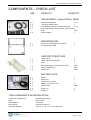
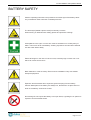
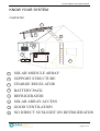
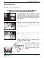
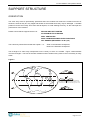
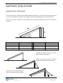
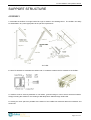
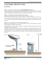
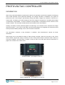
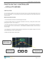
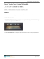
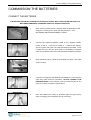
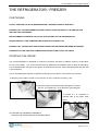
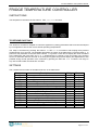
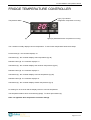
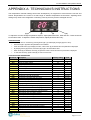
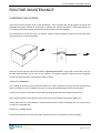
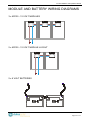
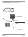
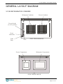
DULAS Solar Powered
VC150 Refrigerator/Freezer
Installation & Operation Manual
June 2010
VC150 Installation and Operation Manual
CONTENTS
SECTION
Page
KNOW YOUR SYSTEM
te c a
SOLAR
Component checklist
3
Battery safety
4
Preparation
Completed system
5
6
SOLAR ARRAY
Photovoltaic module assembly
7
Support structure orientation
Support structure assembly
8
10
Lightning protection
12
ELECTRICAL SYSTEM
Photovoltaic controller information and installation
Battery commissioning
13 - 18
19
THE REFRIGERATOR / FREEZER
Positioning and starting
Loading
20
21
Fridge temperature controller
Appendix A: technician’s instructions
22 - 24
25
Routine maintenance
26 & 27
SYSTEM DIAGRAMS
Photovoltaic module and battery layouts
28
System wiring diagram (Version 1)
System wiring diagram (Version 2)
29
30
General layout diagram
31
Electrical Schematic
Refrigeration circuit diagram
32
33
Page 2 of 34
VC150 Installation and Operation Manual
COMPONENTS – CHECK LIST
REF
PRODUCT
QUANTITY
SOLAR ARRAY (either 270W or 405W)
a. 1
a. 2
KD135 Solar Modules
10m Array Output Cable
a. 3
a. 4
0.5m Module Interconnect Cable Assembly
1 or 2
Bolt, Plain Washer, Nylon Washer, Penny Washer
a. 5
2 or 3
1
& Nut
Pack
Silicon Sealant
1
REFRIGERATOR
b. 1
DULAS VC150 Refrigerator / Freezer
1
b. 2
4m Refrigerator Cable
1
SUPPORT STRUCTURE
c. 1
Unirac rail kit
2
c. 2
Unirac high profile tilt leg kit
2
c. 3
c. 4
Feet
Bolt, Plain Washer, Spring Washer & Nut
4
Pack
c. 5
c. 6
Screws & Wall Plugs
Cable Clips
Pack
Pack
BATTERY PACK
d. 1
d. 2
Battery
Battery box
2
1
d. 3
d. 4
Photovoltaic controller
Battery to controller cable
1
1
d. 5
Spare Fuses
Pack
d. 6
d. 7
Cable Ties
Padlocks
5
3
TOOLS REQUIRED FOR INSTALLATION
Pozidriv No.2 Screwdriver
Slot-head Screwdriver
Pliers
Wire Cutters
Wire Strippers
Drill and Bits
Craft Knife
Hammer and Punch
Adjustable Spanner
Size 10, 11, 13, 14 & 17 mm Spanners
Page 3 of 34
VC150 Installation and Operation Manual
BATTERY SAFETY
Observe operating instructions and position them within sight of the battery! Work
only on batteries under instruction of skilled personnel!
The electrolyte (diluted sulphuric acid) is extremely corrosive
When working on batteries wear safety glasses and protective clothing!
Acid splashes in the eyes or on the skin must be washed out or off with plenty of
water. Then see a doctor immediately. Clothing exposed to acid should be washed
out with water without delay.
Electrical Danger! In the case of a short circuit, extremely high currents can occur
which can cause severe burns.
Block batteries or cells are heavy! Ensure secure installation! Only use suitable
transport equipment!
Explosion and fire hazard due to explosive gases escaping from the battery.
Caution! Metal parts of the battery are always live, therefore do not place items or
tools on the battery! Avoid short circuits!
No smoking! Do not expose the battery to an open flame, a glowing fire or sparks as
explosion and fire hazards exists.
Page 4 of 34
VC150 Installation and Operation Manual
KNOW YOUR SYSTEM
PREPARATION
Before commencing, some time should be dedicated to working out all the aspects concerned in the system
installation.
By following these simple instructions and spending a little time on each, the whole installation process
should be easier.
1)
Check that all components are present, familiarise yourself with them and make sure that everything
has been identified.
2)
Discuss and decide a position for the refrigerator, ensuring that it is well ventilated, dry and not in
direct sunlight. The colder the room, the better the performance.
3)
Work out a position for the solar array ensuring that it faces the correct direction, is at the correct tilt
angle (see page on support structure orientation), no shading will occur, it will not be damaged and it
is accessible for cleaning and maintenance.
4)
Work out the route for the solar array output cable, ensuring that there is sufficient length to reach
the charge regulator.
5)
Choose a position for the batteries that is well ventilated, dry, safe, not in direct sunlight and
accessible for topping up with distilled water. The colder the room the better the performance.
The system, when completely installed should look similar to the drawing below. Each component should
have a sensible, well thought out, safe location, allowing access for routine maintenance.
tec
a
SOLAR
Page 5 of 34
VC150 Installation and Operation Manual
KNOW YOUR SYSTEM
COMPLETED
1
2
3
t
eca
6
7
5
4
8
1
SOLAR MODULE ARRAY
2
SUPPORT STRUCTURE
3
CHARGE REGULATOR
4
5
BATTERY PACK
REFRIGERATOR
6
SOLAR ARRAY ACCESS
7
GOOD VENTILATION
8
NO DIRECT SUNLIGHT ON REFRIGERATOR
Page 6 of 34
VC150 Installation and Operation Manual
SOLAR ARRAY
KYOCERA MODULE ASSEMBLY
PLEASE READ ALL OF THE INSTRUCTIONS THOROUGHLY BEFORE COMMENCING
(FOR 12V WIRING LAYOUTS SEE ‘JUNCTION BOX WIRING DIAGRAMS’)
After ensuring that all the components are present, remove the
solar modules (a.1) from their cardboard boxes and lay them next
to each other on top of the cardboard, with glass facing down. Do
not step on the glass modules. BROKEN MODULES CANNOT BE
USED. Arrange the solar modules so that the junction boxes are all
on the same side.
Interconnect the modules with the cables provided (a.3). The
interconnect cable has a crimped ring terminal at each end which
are easily connected to the Kyocera junction boxes as illustrated
below in Figure 1, (remove plastic nut, screw gland in place,
replace plastic nut and connect cables.)
The array output cable (a. 2) must then be connected to the nearest
module (see System Wiring Diagram), brown or red wire to +, blue
or black wire to -. Ensure that there is sufficient cable to meet the
necessary distance then insert into the junction boxes as performed
previously.
Note : Due to new cable colour regulations brown or red can be
used for +ve and blue or black for –ve until 1/4/06 after which time
only brown and blue will be permissible.
Lift the cover of the junction box by
removing the four screws. Place the ring
terminal into position and tighten up the
terminal screw until it is gripped securely.
Replace the cover of the junction box with
the screws provided ensuring a moisture
proof seal.
Figure 1
Page 7 of 34
VC150 Installation and Operation Manual
SUPPORT STRUCTURE
ORIENTATION
The solar array must be permanently positioned where the modules will receive the maximum amount of
sunshine, however they are very fragile and should not be located where they may be damaged. A suitable
position must be found away from trees and tall objects, to avoid shading the array, as this will impair the
performance of the modules.
Please ensure that the support structure is:
SECURE AND NOT TWISTED
ACCESSIBLE FOR CLEANING
WELL VENTILATED
SAFE FROM SEVERE WEATHER CONDITIONS
NOT SHADED (BETWEEN 7 am & 5 pm)
The solar array should face towards the equator – i.e.
South in the Northern Hemisphere,
North in the Southern Hemisphere.
The tilt angle of a solar array is dependent on the country in which it is located. Figure 2 demonstrates
common tilt angles. The front of the solar modules must be cleaned every week or when necessary in dusty
areas.
Figure 2
PV Modules near the Equator should be positioned
with a slight (10-15 ) tilt fac ing North or South in order
to allow rain to run off them also keeping them c lean.
Page 8 of 34
VC150 Installation and Operation Manual
SUPPORT STRUCTURE
ORIENTATION CONTINUED
The support structure is made from pre-drilled galvanised steel angle. If your mounting area cannot be level
e.g. you have a sloping roof, then the correct angle must be made by adjusting the foot mounting holes.
Use the ratios below to calculate your appropriate angle and follow the diagrams to position the structure
accurately.
Required Angle (A)
Approx. Ratio (x : y)
Required Angle (A)
Approx. Ratio (x : y)
10°
6:1
30°
2:1
15°
4:1
35°
1.75 : 1
20°
3:1
40°
1.5 : 1
25°
2.4 : 1
45°
1.4 : 1
Changing the position or length of the Tilt
legs can alter module angles.
Always ensure that all bolts are secured
tightly after alterations have been made.
A protractor can be used to determine
if the correct angle has been acquired.
Page 9 of 34
VC150 Installation and Operation Manual
SUPPORT STRUCTURE
ASSEMBLY
1. Assemble the UniRac TLH High Profile Tilt Legs as shown in the drawing below. The UniRac can easily
be assembled in any order appropriate to the job site requirements.
TILT LEG
2. Use 3/8” hardware to assemble the UniRac and ¼” hardware to attach the PV modules to the UniRac.
3. UniRacs must be securely attached to roof rafters, ground footings or other secure structural features.
Simply screwing the UniRac to roof decking is not adequate to withstand high wind loads.
4. Leaving as much space as possible at the bottom of the UniRac will minimize debris accumulation and
snow load.
Page 10 of 34
VC150 Installation and Operation Manual
SUPPORT STRUCTURE
LOCATING MOUNTING FEET
5. The drawing below shows two options for setting the width of the Mounting Feet. If possible, mount a PV
module to the UniRails to determine the best attachment method for obtaining the proper distance between
the Mounting Feet.
TILT LEG
6. On UniRacs Tilt Leg Kits, rack tilt can be determined by:
A – Raising or lowering the Tilt Leg,
B – Moving the Tilt Leg up or down along the UniRail,
C – Adjusting the distance between the lower and upper Mounting Feet before final installation.
COMPLETED UNIRAC TLH HIGH-PROFILE TILT
LEGS INSTALLATION
(ADJUSTABLE LEG)
Page 11 of 34
VC150 Installation and Operation Manual
LIGHTNING PROTECTION
MEASURES
LEVEL 1 – NO PROTECTIVE MEASURES – NOT RECOMMENDED BY DULAS LTD
Failure to provide protection measures against lightning strike risks damage to the equipment. In the event
of lightning striking the roof mounted Solar Array, high voltage may be conducted towards the refrigerator
system. This high voltage may damage the electronic components of the system.
LEVEL 2 – LIMITED PROTECTIVE MEASURES (Normally Supplied)
We strongly recommend that at least this level of protection be installed – see figure 1.
Install an earth electrode (earth rod) (A) outside the building – the earth rod should be at least 2m long.
Connect the earth rod with good quality wire (at least 6mm²) to the Solar Array and support structure (wire
B). The earth wire should follow the shortest and straightest path between the support structure and the
earth rod.
LEVEL 3 - FULL LIGHTNING CONDUCTOR SYSTEM (Not Supplied)
Assess the risk of lightning strike. Look at other local buildings – are they fitted with lightning conductors?
Ask local people if TV aerials etc often get struck?
If the installation is at high risk of lightning strike then an additional lightning conductor and separate earth
rod should be installed – see figure 2.
In addition to level 2 protection, install a second earth electrode (D). The distance between the two earth
electrodes must be more than their length. Erect an Air Terminal or Lightning Conductor (D) next to the
second earth electrode. The Air Terminal must exceed the height of the Solar Array such that the Solar
Array falls within a 45º cone centred on the Air Terminal – this is the area that is protected by the Air
Terminal.
Figure 1.
Figure 2.
Page 12 of 34
VC150 Installation and Operation Manual
PHOTOVOLTAIC CONTROLLER
INFORMATION
When using Lead-Acid batteries in photovoltaic systems it is important to protect them against overcharging
which would otherwise cause permanent damage. The Charge Controller is installed in the system to
perform this task. Over-charge is prevented by limiting the battery voltage to a maximum of around 13.7
Volts at 25°C. The battery can be left charging at this ‘float’ voltage for long periods. The battery float voltage
is temperature compensated. In order to measure the temperature, a temperature sensor is built in to the
charge controller. The Controller should therefore be mounted close to the batteries.
Similarly, the battery must be protected against over-discharge. The Controller has an automatic low voltage
disconnect facility. In the event of the battery becoming discharged, the refrigerator will be disconnected
before permanent battery damage occurs. Re-connection is automatic.
The Photovoltaic Controller is fully automatic in operation. See manufacturer’s manual for further
information.
Dulas supply one of two different models of Steca Charge controller: either the PR series or the Tarom
series. Please compare the charge controller you have to the pictures below to determine which model you
have been supplied. The instructions on pages 14 and 15 refer to the PR series and the instructions on
pages 16 to 18 refer to the Tarom series.
STECA PR3030 – go to pages 14 and 15
STECA TAROM 235 – go to pages 16, 17 and 18
Page 13 of 34
VC150 Installation and Operation Manual
PHOTOVOLTAIC CONTROLLER
– STECA PR SERIES
STECA PR SERIES CHARGE CONTROLLER
OPERATION
The PR series controller is fully automatic in operation. See Steca manual for full information.
CONTROLLER FUNCTIONS
The display window on the front panel shows system information and error messages, the left button on the
front panel can be used to switch display windows or calling up settings and the right button is used as a
manual load switch, or confirmation button in the programme mode. The three displays, which are the most
relevant to the operation of the refrigerator, are as follows:
1. CORRECT OPERATION: Indicated by a smiling face in the display window. A sad face indicates a fault.
The reference number in the display can then be looked up in the manual to give the meaning of the error
and the cause/remedy.
2. STATE OF CHARGE: Indicated by the bar graph (SOC:) and a percentage on the display. When the
state of charge is 50% or less, icepacks should not be frozen.
3. LOAD DISCONNECTION: The refrigerator is disconnected when the state of charge drops to 30%. The
SOC bar value, or the voltage value, flashes. The face looks sad until the reconnection set point is reached.
THE LCD ALSO PERFORMS VARIOUS OTHER FUNCTIONS. CONSULT THE MANUFACTURER’S
HANDBOOK FOR FURTHER INFORMATION.
Page 14 of 34
VC150 Installation and Operation Manual
PHOTOVOLTAIC CONTROLLER
– STECA PR SERIES
INSTALLATION
The unit should be installed in a dry location with clear space around it, to allow heat generated at the rear of
the unit to be dissipated. The unit is fixed to the wall so that the terminals are at the bottom and the fins
running vertically.
INSTALLATION INSTRUCTIONS:
1. Fix the Photovoltaic Controller to the wall with plugs and screws.
2. Connect the battery cable to the central pair of terminals on the unit (2). Taking care to ensure correct
polarity (brown or red to +, blue or black to -).
3. The array output cable (a.2) must be connected AFTER the batteries, to the left hand pair of terminals on
the unit (1) (brown or red to +, blue or black to -). BE AWARE OF LARGE VOLTAGES. Cover the array or
connect at night.
4. The refrigerator is connected to the right hand pair of terminals (3) on the regulator, taking care to ensure
correct polarity (brown or red to +,blue or black to -).
5. Support the cables using the clips provided.
Display window for
system information
and error messages
Button for switching
display windows or
calling up settings
1
2
3
Manual load switch, or
confirmation button in
programme mode
Page 15 of 34
VC150 Installation and Operation Manual
PHOTOVOLTAIC CONTROLLER
– STECA TAROM SERIES
STECA TAROM SERIES CHARGE CONTROLLER
OPERATION
The Photovoltaic Controller is fully automatic in operation. See manufacturer’s manual for information.
CONTROLLER FUNCTIONS
1. STATE OF CHARGE: Indicated by a percentage at the top left of the display. When the state of charge
is 50% or less, icepacks should not be frozen.
2. LOAD DISCONNECTION: The refrigerator is disconnected when the state of charge drops below 30%.
Page 16 of 34
VC150 Installation and Operation Manual
PHOTOVOLTAIC CONTROLLER
– STECA TAROM SERIES
3. DISPLAY FUNCTIONS (for 35a and 45a)
BAT: Battery voltage
IN: Charge (PV) current
OUT:
Discharge
(fridge) current
SOC: Battery state of
This section
The rotating display goes through the following screens:
SOC
=
xx %
State of charge of the battery
U BAT =
xx V
Voltage of the battery
I accu
=
+ xx A
Battery current (charging is +ve)
I out
=
xx A
Fridge current
I in
=
xx A
Charge current
I mod
=
xx
A
Current available from PV
manual auto
System is in automatic mode
normal charge
Indicates ‘normal’ or ‘boost’ charge
fixed electrolyte
Controller is pre-set for sealed gel battery
4. The display also indicates various system faults and other functions. Consult the manufacturer’s manual
for further information.
Page 17 of 34
VC150 Installation and Operation Manual
PHOTOVOLTAIC CONTROLLER
– STECA TAROM SERIES
INSTALLATION
The unit should be installed in a dry location with clear space around it, to allow heat generated at the rear of
the unit to be dissipated. The unit is fixed to the wall so that the terminals are at the bottom and the fins
running vertically.
Installation Instructions
1. Fix the Photovoltaic Controller to the wall with plugs and screws.
2. Connect the refrigerator to the right hand pair of terminals (A) on the controller, taking care to ensure
correct polarity (brown or red to +,blue or black to -).
3. Connect the battery cable to the central pair of terminals on the unit (B), taking care to ensure
correct polarity (brown or red to +, blue or black to -).
4. Install the battery fuse.
5. Check the controller display is working, then connect the array output cable to the left hand pair of
terminals on the controller (C), (brown or red to +, blue or black to -).
6. Support the cables using the clips provided.
C
B
A
Page 18 of 34
VC150 Installation and Operation Manual
COMMISSION THE BATTERIES
CONNECT THE BATTERIES
THE BATTERY BOX MUST ALWAYS BE LOCATED IN A VERY WELL VENTILATED AREA AS THE
BATTERIES GENERATE HYDROGEN, WHICH IS AN EXPLOSIVE GAS.
1.
After choosing a final location, carefully place the batteries into the
empty box, ensuring not to lift by the terminal points. THE
BATTERIES ARE NOW EXTREMELY HEAVY.
2.
Connect the battery-to-regulator cable to the regulator FIRST,
brown or red to + and blue or black to – THEN to the battery.
Secure in place using the nuts, bolts and washers provided. Insert
a spare fuse (d.7) into the fuse holder on the battery-to-regulator
cable. Any problems refer to the manufacturers handbook provided.
3.
Apply petroleum jelly or similar to each battery terminal – this helps
avoid corrosion.
4.
Commence charging of the batteries immediately by connecting the
solar array cable to the PV Controller. DO NOT CONNECT THE
REFRIGERATOR as the batteries need an initial charging of two
good sunny days for optimum performance.
5.
Once the batteries are ready for operation (after two good sunny
days of charging), the refrigerator can be connected.
Page 19 of 34
VC150 Installation and Operation Manual
THE REFRIGERATOR / FREEZER
POSITIONING
DO NOT POSITION THE VC150 REFRIGERATOR / FREEZER IN DIRECT SUNLIGHT
ENSURE THAT THE REFRIGERATOR IS WELL VENTILATED, ESPECIALLY THE VENTILATION
GRILLES AND CONDENSER.
WE RECOMMEND LEAVING A 500mm GAP AT EACH END OF THE REFRIGERATOR
NEVER OBSTRUCT THE TEMPERATURE OR REGULATOR DISPLAYS
ENSURE THAT THE BATTERY BOX AND BATTERIES CAN BE INSPECTED WHEN NECESSARY
NEVER BLOCK THE CIRCULAR COMPRESSOR VENTILATION FAN AT THE FRONT
STARTING THE FRIDGE
The VC150 Refrigerator is designed for continuous operation, therefore an ON/OFF switch is not provided,
as it is not necessary. The VC150 Freezer however, does have an ON/OFF switch to allow for defrosting.
This is situated at the rear right of the cabinet, as viewed from the front, above the cable gland (see General
Layout Diagram).
The VC150 Refrigerator/Freezer is operational when the power cable is connected to the controller.
a) Strip the power cable to reveal 10 mm of brown or red (+) and blue or black (-) wire.
b) Insert the cable into the black strain relief gland, located at
the rear, see ‘Cable Entry’ in the General Layout Diagram.
c) Connect to + & - terminals on
opposite side of the strain relief
gland.
d) TIGHTEN THE TERMINALS SECURELY,
TIGHTEN THE STRAIN RELIEF GLAND SECURELY.
Page 20 of 34
VC150 Installation and Operation Manual
THE REFRIGERATOR / FREEZER
LOADING
IN ORDER TO KEEP INTERNAL TEMPERATURES OPTIMUM AND MINIMISE ENERGY
CONSUMPTION, ONLY OPEN THE LID WHEN STRICTLY NECESSARY AND ALWAYS REPLACE
INNER FOAM LIDS
The VC150 Refrigerator / Freezer has two compartments, see General Layout Diagram:
1) The smaller Freezer (ice pack) compartment to the left.
2) The larger Refrigerator (vaccine) compartment to the right.
ICE PACKS: When frozen ice packs are needed; switch the freezer ON, insert ice packs with basket into the
LEFT compartment. Ice packs must be in contact with the freezer compartment walls for efficient freezing.
A wire basket is provided to hold the ice packs against the walls of the compartment. Only three sides of the
compartment can be used for freezing ice packs as the fourth has the thermostat sensor mounted on it. The
sensor is protected by a small wire cage. Ice packs are removed by simply reaching inside the basket, and
sliding the ice packs up and out of the ice freezing area. Frozen ice packs can be stored in the space inside
the wire basket. The freezer can freeze nine ice packs simultaneously. Remember to switch the freezer
OFF when not in use – to save energy.
WARNING: STANDARD SYSTEMS ARE DESIGNED TO ONLY FREEZE 2.4 KG’s OF ICE
PER 24 HOURS, FREEZING MORE WILL FLATTEN THE BATTERIES.
VACCINES: The refrigerator compartment situated to the RIGHT is in constant operation. The wire baskets
in the refrigerator compartment are designed to prevent the contents of the compartment from touching the
cold sides, and to encourage the circulation of air. Good air circulation will help the refrigerator to maintain
an even temperature throughout the compartment. The contents of the compartment should be arranged to
allow good air circulation. In order to save energy, try to keep the lid open for as short a time as possible.
Try to allocate a certain space for each different type of vaccine, so that they may be located rapidly. Check
the vaccine labels and adhere to any special requirements, always use before expiry date (store older
vaccines on top).
WARNING : ALWAYS FOLLOW THESE VACCINE STORAGE GUIDELINES
= Refrigerator Wall
= Vaccine Box
= 15 mm Air Space
TOP VIEW
SIDE VIEW
Page 21 of 34
VC150 Installation and Operation Manual
FRIDGE TEMPERATURE CONTROLLER
Does the controller on your fridge/freezer
look like this?
If so go to page 23
Does the controller on your fridge/freezer
look like this?
If so go to page 24
Page 22 of 34
VC150 Installation and Operation Manual
FRIDGE TEMPERATURE CONTROLLER
INSTRUCTIONS
The temperature controller has four buttons: SET, <<-<, >->> and AUX.
TO BE DONE ONCE ONLY
The electronic controller is adapted to control the appliance by setting parameters that have been developed
by our engineers to ensure the correct internal operating temperatures.
The setup is accessed by pressing the buttons + SET + in succession and keeping them pressed
simultaneously for 3 seconds. The available parameters are shown in the table below. Press the button to
pass from one parameter to the next and the button to go back. Press SET to display the value correlated
to the parameter and press SET and or simultaneously to change it. Exit from setup is by pressing
AUX or is automatic after 30 seconds of not using the keypad. Set point SP display and adjustment is also
possible during normal operation of the controller by pressing the SET and or buttons. The range in
any case remains within the limits SPL and SPH.
SETTINGS
The controller has a number of variables as shown in the table below.
Parameter
SCL
SPL
SPH
SP
HYS
CRT
CDC
DFR
DTO
DDY
ATL
ATH
ATD
ACC
OS1
SIM
Description
Readout scale
Minimum temperature set point
Maximum temperature set point
Effective temperature set point
Thermostat hysteresis
Compressor rest time
Compressor regulation with sensor T1 failure
Defrosting frequency /24h
Defrosting duration
Defrosting display control
Low alarm differential
High alarm differential
Temperature alarm delay
Condenser periodic cleaning
Sensor T1 correction
Display slowdown
Fridge
2
4
4
4
3
3
5
1
1
1
-3
2
15
0
0
20
Freezer
2
-7
-7
-7
4
3
5
1
1
1
-8
3
15
0
0
20
Page 23 of 34
VC150 Installation and Operation Manual
FRIDGE TEMPERATURE CONTROLLER
Light (T1) indicates
refrigerator compressor is running
Temperature Alarm
(1)
Light (T2) indicates freezer compressor is running
The controller normally displays vaccine temperature. To see freezer temperature follow these steps:
Press button (1) - the controller displays ‘hi’
Hold button (1) - the controller displays max temperature (eg 08)
Release button (1) - the controller displays ‘Lo’
Hold button (1) - the controller displays the minimum temperature (eg 03)
Release button (1) - the controller displays ‘t1’
Hold button (1) - the controller displays vaccine temperature (eg 06)
Release button (1) - the controller displays ‘t2’
Hold button (1) - the controller displays freezer temperature (eg -6)
Do nothing for 10 seconds and the display reverts to vaccine temperature.
The temperature alarm has a sound warning (beep). To cancel press button (1)
Note: see appendix A for temperature controller settings.
Page 24 of 34
VC150 Installation and Operation Manual
APPENDIX A: TECHNICIAN’S INSTRUCTIONS
The temperature controller settings have been developed by our engineers to ensure that the vaccine and
freezer temperatures are correct for a wide range of ambient temperature environments. Adjusting these
settings may result in the refrigerator not working correctly and may result in damaged vaccine.
(1)
(2)
(3)
(4)
To adjust the vaccine storage temperature setpoint, adjust parameters SPL, SPH and SP1. These should all
be the same value. To adjust the freezer temperature, adjust parameter SP2 only.
CONFIGURATION
•
The setup menu is accessed by pressing button (4) + (1) until display changes (approx 6 secs).
•
With button (2) or (3) select the parameter to be modified.
•
Press and hold button (1) to display the value, when button (1) is released the next parameter is displayed.
•
By keeping button (1) pressed, use button (2) or (3) to set the desired value.
•
When button (1) is released, the newly programmed value is stored and the next parameter is displayed.
•
To exit from the setup, press button (4) or wait for 30 seconds.
CONFIGURATION PARAMETERS
Parameter Description
SCL
Readout scale
SPL
Minimum fridge setpoint
SPH
Maximum fridge setpoint
SP1
Fridge Setpoint
HY1
OFF/ON fridge differential
SP2
Freezer Setpoint
HY2
OFF/ON freezer differential
CRT
Compressor rest time
CT1
Compressor run with probe faulty
CT2
Compressor stop with probe faulty
CSD
Compressor stop delay after door open
DFR
Defrost frequency expressed in cycles/24 hours
DTO
Maximum defrost duration
DDY
Display during defrost
ATM
Alarm Threshold management (fridge)
ALA
Low temperature alarm threshold (fridge)
AHA
High temperature alarm threshold (fridge)
ATD
Delay before alarm temperature warning (fridge)
ADO
Delay before door open alarm warning
SB
Stand-by button enabling
DS
Door switch input enabling
INP
Temperature sensor selection
OS1
Fridge probe offset
T2
Second Probe
OS2
Freezer probe offset
TLD
Delay for min and max temperature logging
SIM
Display slowdown
ADR
Address for PC communication
Factory setting
2°C
03
03
03
03
-07
04
3
3
6
0
0
20
10
ABS
01
10
15
0
NO
NO
SN4
-02
YES
-02
5
20
01
Units
°C
°C
°C
°C
°C
°C
minutes
minutes
minutes
minutes
minutes
minutes
°C
°C
minutes
minutes
Flag
Flag
°C
Flag
°C
minutes
Page 25 of 34
VC150 Installation and Operation Manual
ROUTINE MAINTENANCE
CHECK TEMPERATURES
The temperature inside the refrigerator should be checked each morning and afternoon. The temperature
must be between 2°C and +8°C. If the temperature i s not within this range then something is wrong and the
vaccines will be unusable. Consult the W.H.O. Fault Finding and Repair of Photovoltaic Refrigerators
(provided with each refrigerator).
Check the temperature by placing a thermometer next to the temperature sensor (situated at the rear of the
right hand compartment) and closing the lid. After five minutes, remove the thermometer, read and record
the temperature on a relevant data sheet.
CHECK LIGHTS
Check that the warning lights on the Photovoltaic Charge Regulator are not lit, and that operation is normal.
If there is a problem then record this and refer to the W.H.O Fault Finding and Repair of Photovoltaic
Refrigerators (attached).
DEFROSTING
If there is a build up of ice (5 mm or more) on the walls of the freezer, then it must be removed by defrosting.
The refrigerator can be kept running, or cleaned at the same time.
WARNING: NEVER REMOVE ICE WITH KNIVES OR SHARP OBJECTS OR USE SCOURING POWDER,
ABRASIVE CLEANERS OR STEEL WOOL AS THIS WILL DAMAGE THE METAL PLATING AND
CAUSE CORROSION.
1.) If the refrigerator is to be cleaned, move the vaccines into another fridge or a cold box, which can ensure
the correct temperature is sustained throughout the defrosting process.
2.) Switch the freezer OFF (see General Layout Diagram).
3.) Open the outer lid, remove the appropriate inner lids, leaving the freezer for at least 30 minutes to warm
up.
4.) When possible, remove ice with fingers or wooden / plastic tools.
5.) Hand-warm water can be used to assist the defrosting process.
6.) Dry the ice compartment after the ice has melted and clean the vaccine compartment with soapy water,
then dry it carefully.
7.) Clean the outer lid seal (talcum powder can be sprinkled on it to prevent it from sticking).
8.) Switch the freezer back ON and close the lid.
9.) After 2 hours check the temperature. Wait until the inside temperature has fallen to between 2°C and
+8°C and the compressor has stopped running continu ously.
10.) Return the vaccines to the refrigerator and close the lids.
DEFROSTING MUST BE COMPLETED AS QUICKLY AS POSSIBLE, TO PREVENT
DAMAGE TO THE VACCINES
Page 26 of 34
VC150 Installation and Operation Manual
ROUTINE MAINTENANCE
CHECKING THE LID SEAL
The lid seal is the most likely area of heat penetration. If the lid hinges are wrongly aligned or the lid seal
damaged, the system will have to work harder to maintain the vaccine temperature. When the batteries run
out of energy the system will fail, therefore the lid seal must be checked regularly.
The easiest way to check your seal is to position a piece of paper between the lid and the wall, then after
closing the lid, try to remove the paper.
LID
PAPER
WALL
OF
Vc150
Check the seal in this way around the entire lid, especially the corners. If the paper moves easily, then the
lid seal needs attention, it may need to be re-glued or completely replaced, alternatively the refrigerator
hinges may need adjusting so that the lid is sitting correctly.
CHECK FOR SHADOWS
Any shading of the array (solar panels) will reduce it’s output, therefore the array must be checked three
times in one day, at 7 am, 12 midday and 5 pm, to ensure all possible shade sources are eliminated.
Cut back any bushes or trees which cause shading, seeking permission and explaining why firstly.
Move anything that has been placed in front of the array, and may block the sunshine falling on it.
If there have been any new buildings or structures erected which cause shadowing, then the array must be
moved to an unshaded area.
CHECK ALL CONNECTIONS
Check each electrical connection thoroughly, making sure every nut and bolt, are secured tightly.
Page 27 of 34
VC150 Installation and Operation Manual
MODULE AND BATTERY WIRING DIAGRAMS
3 x KD135 - 12 VOLT MODULES
2 x KD135 - 12 VOLT MODULE LAYOUT
2 x 6 VOLT BATTERIES
Page 28 of 34
VC150 Installation and Operation Manual
SYSTEM WIRING DIAGRAM (Version 1)
VC150 REFRIGERATOR / FREEZER
Module interconnect cable
Solar Module Array
Module Interconnect Cable
Array Output Cable
!
Photovoltaic
Controller
3530A
or 45A
Photovoltaic
charge
controller.
Fridge Power Cable
Battery Cable
Batteries
VC150 Refrigerator
Page 29 of 34
VC150 Installation and Operation Manual
SYSTEM WIRING DIAGRAM (Version 2)
VC150 REFRIGERATOR / FREEZER
Page 30 of 34
VC150 Installation and Operation Manual
GENERAL LAYOUT DIAGRAM
VC150 REFRIGERATOR / FREEZER
Refrigerator Condenser
Freezer Condenser
Freezer Switch
(in ‘ON’ position)
Power
Connection
Cable
Entry
Fuses
Freezer Compartment
VIEW FROM BEHIND
Refrigerator Compartment
VIEW FROM ABOVE
Page 31 of 34
VC150 Installation and Operation Manual
ELECTRICAL SCHEMATIC
VC150 REFRIGERATOR / FREEZER
Parts List
Compressors C1147
Compressor Controllers
Thermostats
Switch on Freezer only
Fan
BD 35
101N0210
AT-5BQ8L-1PS
CV465
E2076
Page 32 of 34
VC150 Installation and Operation Manual
REFRIGERATION CIRCUIT DIAGRAM
VC150 REFRIGERATOR
Capillary
(120’ x 0.031”)
Evaporator
(Assy No: EV8661)
Accumulator
(Part No: E L1027)
Suction
46” x 5/16”
Drier
(Part No: N1184)
Condenser
(Part No: N1111
or N1235)
M
Compressor C1147
(Part No: BD 35)
VC150 FREEZER
Capillary
(120’ x 0.026”)
Evaporator
(Assy No: Ev8662)
Accumulator
(Part No: E L1027)
Suction
72” x 5/16”
Drier
(Part No: N1184)
Condenser
(Part No: N1111
or N1235)
M
Compressor C1147
(Part No: BD 35)
Page 33 of 34
VC150 Installation and Operation Manual
For more information contact:
DULAS Ltd, Dyfi Eco Park, Machynlleth, Powys, Wales SY20 8AX
tel: +44(0)1654-705000 fax: +44(0)1654-703000 e-mail: [email protected]
website: www.dulas.org.uk
Page 34 of 34


![[ES] Smart Energy Control Manual de Instrucciones y de Uso](http://vs1.manualzilla.com/store/data/006255326_1-bcb3ba9c27cbad56c6ef2fe6103a1f45-150x150.png)