1
MITSUBISHI
VVVF TRANSISTOR INVERTER
- INSTRUCTION MANUAL -
0
A
.-
.
MlTSUBlSHl
ELECTRIC
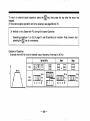
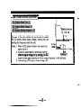
Introduction
Thank you for your purchase of MiBubishi Micro-Inverter FREQROL-2024-UL.
Before operating the inverter, read this manual carefully. Please deliver this instruction manual to the
actual user of the inverter.
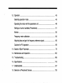
CONTENTS
h
Instructions
1. Precautions......................................................................................................
1
2. Block Diagram and Description ......................................................................
7
3 . Preparation before Operation .........................................................................
11
4 . Apparatus and Components to be Prepared before Operation ....................
13
5 . Installation .......................................................................................................
15
6. Wiring ...............................................................................................................
17
7 . Pre-OperationSettings ...................................................................................
26
.
9 . Using the Parameter Unit ...............................................................................
10. Parameter Unit Installation .............................................................................
11. Outline of Parameter Unit Functions ..............................................................
30
8 Operation.........................................................................................................
38
40
42
-
12. Operation .........................................................................................................
43
Selecting operation mode ...............................................................................
43
Operating the motor with the parameter unit .................................................
46
Settings of control variables (Parameters) ....................................................
51
Monitor .............................................................................................................
55
Frequency meter calibration ...........................................................................
64
Adjusting bias and gain for frequency reference signal ................................
66
Cautions for PU operation ..............................................................................
69
13. Details of Each Parameter..............................................................................
72
14. Maintenance and Inspection...........................................................................
102
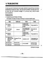
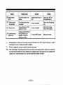
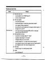
15 . Troubleshooting
..............................................................................................
109
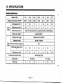
16. Specifications ................................................................................................
113
17. DIMENSIONS..................................................................................................
127
18 . Selection of Peripheral Devices .....................................................................
133
I
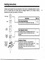
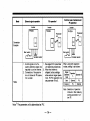
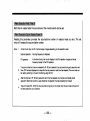
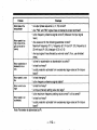
Handling Instructions
Improper use and operation may cause malfunction of the inverter or considerable reduction in service
life. In an extreme case, the inverter might be damaged. Handle the unit correctly, following
descriptions and notes in each section of this manual.
Power supply
~
~~
Instructlons
Fuses
BUR
I
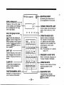
Supply Speclflcatlon
.Power
Use the inverter within its allowable power supply range.
I Refer to: I
P.113
Circuit
Breaker
Magnetic
contactor
(MC)
I
I
I
lnstallatlon of Reactor
For power factor improvement, or when installing the
Power factor
improving
AC reactor
(FR-BAL)
I
l
l
I l l
wiring distance of 10 m or shorter, use of a reactor is
recommended. Choose a reactor according to the inverter
model and size.
-'
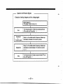
Handling Instructions
A
til
installation Location
The service life of the inverter depends on ambient
temperature. Ambient temperature should be as low as
possible, so that the allowable range may not be exceeded.
When housing the inverter in an enclosure, this point
should be considered.
p.9,, 5,,6
Wirlng
Miswiring might cause damage to the inverter. Keep a
sufficient distance between the control signal lines and the
main circuit so as not to cause noise interference.
P.9,20
Grounding
Motor
designed) to the output.
Use of such equipment may cause damage to either inverter or the
Ground the motor securely
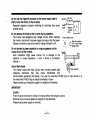
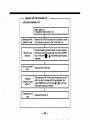
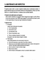
1. PRECAUTIONS
Use the Inverter wlthln the allowable ambient temperature range.
The service life of the inverter depends on ambient temperature.
Ambient temperature should be as low as possible, such that the
allowable range is not exceeded. Care should be taken for installation
direction and the environment.
(See page 1516.)
--
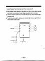
Do not perform Inverter contlnulty test.
When measuring isolation resistance of power line or motor, disconnect
connections to the inverter or short-circuit across terminals as follows.Pow
Do not perform a continuity test on the control circuit.
Conlinuily
tester
FREQROL
Motor
Continuity
tester
If power voltage Is applied to the output circuit of the Inverter, it will
be damaged.
If the power voltage is applied to terminals U, V, W, the inverter will be
damaged. Check to ensure that wiring and operation sequence (such as
commercial power source selector circuit) are correct. Do not supply a
voltage exceeding the allowable voltage range.
I .
-1-
~
Do not use the magnetic contactor at the power supply side to
start or stop the motor (or the inverter).
Repeated magnetic contactor switching for startktop may cause
inverter failure.
Do not access the inside of the inverter during operatlon.
The inverter has dangerous high voltage circuits. When checking
the inverter, disconnect the power supply and ensure that the power
indicator (commonly used as an electric charge indicator) is off.
0N.OFFI
oN’oFF+.,ON.OFF!
supply
P
Magnetic
o
contactor
~
A
(MC)
Power indicator lamp
\
/
When the indicator
/
\
charge exisIs.
Do not connect a power capacltor or surge suppressor on the
output circuit of the inverter.
Such installation might cause inverter trip or damage to the
capacitor or surge suppressor. If such a device is connected,
remove it.
I
r
About Radio Nolse
The inverter output and input circuits (main circuits) contain high
frequency harmonics that may cause interference with
communication equipment (AM radios). If so, use of a noise filter FR-BIF (only for input circuit) or a
line noise filter FR-BLF help to reduce the effects of noise.
Please contact your mitsubishi supplier for additional information.
IM PORTANT
COVER
Power must be removed for at least 3 minutes, before removing any covers.
Removal of any covers exposes the operator to live terminals.
Please ensure power supply is removed.
-2-
~
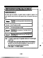
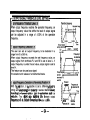
PRECAUTIONS ON USE
Carefully read the entire instruction manual.
1.
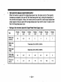
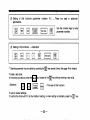
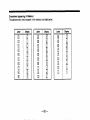
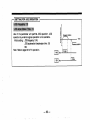
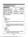
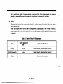
These parameters refer to maximum frequency when the Inverter is supplied.
When the inverter is supplied, the inverter output frequency is 60 Hz when the external frequency
reference signal is DC 5 V (1OV) or 20 mA. However, parameters (see below) that set the
maximum output frequency have a set value over 60 Hz.
Parsmetar number
Panmeter name
20
Frequency for 5 V input
39
Frequency for 20 rnA input
Control varlabie at shipment
‘60.5-63
HZ
.
‘ The parameter at shipment (60 Hz) that appears on pages 69,70 and 71 of this instruction
manual should be interpreted to be the above.
Note:
To adjust the relationship between the frequency reference signal and output frequency, follow the
setting procedures described on page 29 of this instruction manual.
-3-
r
~~
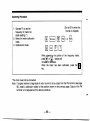
Inverter
(>10
Frequency reference potentiometer
(voltage signal)
Pr.20
( 2
( 0 - 5 V o r 0 - 1 0 V)
,.
5
Frequency reference signal
(current signal)
Pr.39
common
/’
-b4
(4-20mA)
-4I
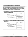
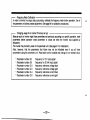
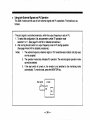
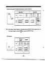
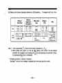
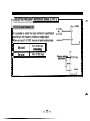
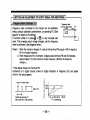
2. Operation of the Parameter Unit When Using the Output shutoff Function
When using the parameter unit in the external signal operation mode, pressing the P U O P key on
the parameter unit cannot select the P U operation mode if the output shutoff signal (MRS
terminal) and start signal (STF or STR terminal) are in the following conditions.
1.
After the operator turned the output shutoff signal ON while the start signal was ON, the operator has turned off the start signal alone.
.....
Start sianal
across terminals STF (STR) and SD
OutDut shutoff sianal .....
'across terminals MRS and SD
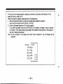
2.
I 1
OFF
I
n
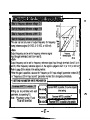
In the condition that the output shutoff signal alone was ON, the operator turned the start signal from ON to OFF.
Start signal .....
across terminals STF (STR) and SD
Output shutoff signal .....
across terminals MRS and SD
-5-
EF
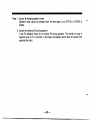
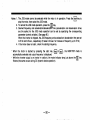
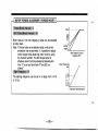
To select the PU operation mode:
First, break connection between terminals MRS and SD,then press the PU OP key.
Note: When the operator has changed the function of terminal MRS from ’output shutoff’ to ’second
accelerationldeceleration time selection’, it is possible to select the PU operation mode on the
condition that the start signal is OFF.
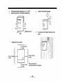
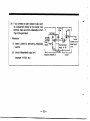
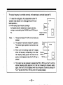
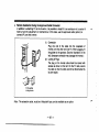
3. Attachlng the Front Cover
When attaching the front cover, locate the lower lugs first, into the main cover.
Bring the upper part of front cover to the main cover and press firmly.
it will “click” when in the correct position.
-6-
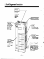
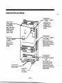
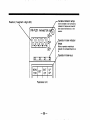
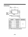
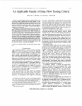
2. Block Diagram and Description
Front cover
To remove the
front cover, press
the latch and
ease the cover
forward.
/
Mounting hole (four positions)
Name plate
The name plate shows
type of series and
capacity in kW
(See next page.)
k.
The inverter type, capacity,
etc. are on the rating plate.
Front cover
B
Remove this cover to
expose the terminal
block. Power
be
removed.
w
-7-
supvlied. an accessory cover is
mounted in its place
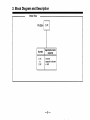
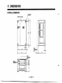
2. Block Diagram and Description
Model Size
FR-2024-
T
3.7K
I
Symbol
0.1 K
to
3.7K
Applicable motor
caeacltv
Inverter
capacity is shown
in kW.
-8-
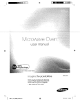
Inverter wlth the Front Cover Removed
I
I
1
Power indicator
lam0 (POWER)
The parameter unit or
connection cable is
connected through this
connector.
Lights up when power is
supplied. (Commonly
used for indicating
capacitor charge.)
Lights up when the
protective circuit is
activated.
1
1
Signals such as the start and
frequency reference signals are
transmitted through connections
to this terminal block.
Terminal block for
power supply and
motor
J
(page 20)
The input power source and
motor are connected to this
front cover
(two positions)
1
-9-
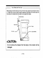
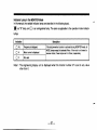
How to Remove the Front Cover
While pressing the removal latch(s) at the top of the front cover, ease the cover forward to remove
it. To attach the front cover, insert the lugs (two positions) at the bottom of of the front cover into
the sockets at the chassis bottom and press the cover against the chassis.
\
Press the latch
(8)
Ease the cover
Chassis
Front cover
<CAUTION>
Lug (two positions)
b
Do not remove the chassis from the body or the inverter will be
damaged.
-10I
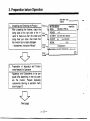
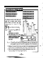
3. PreDaration before Operation
Applicable motor
capacity
1.
Unpacking and Checking the Product
After unpackina the inverter, check the
rating plate at-the right side of the inverter to make sure that the model and
rating meet your order. Also check that
the inverter has not been damaged.
Accessories, Instruction Manual
.
Type
7MlTSUBlSHl
MODEL
output
1
n
2.
INVERTER
FR-2024-0.75K-UL
POWER
1 HP
AC INPUT 3HP 2OOV-230V 50/60Hz
OUTPUT
5A
max 200-230V
SERIAL
0151
Input
ratina
1-
TC100A08 1 0 5 1
AMITSUBISHI
ELECTRIC CORPORATION
MADE I N J A P ~ N
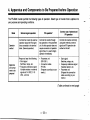
I 3
Preparation of Apparatus and Components Needed for Operation
Apparatus and Components to be prepared differ depending on how you operate the inverter. Prepare necessary
components referring to operation methods on page 13.
(Next page)
-11
-
stallation location, installation direction, and
surrounding space so as not to cause a reduction in the inverter service life or performance.
~~
4.
~
Wiring
Connect the power source, motor, and operation signal (control signals) to the terminal
block. Improper wiring may cause damage
to the inverter.
-12-
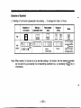
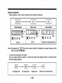
Mode
Common use of external end
PU oparatlon
PU opsrrtlon
External signal opemtlon
Inverter
Inverter
Inverter
I
FR-Z024
I
FR -2024
Parameter
unit
r"":
Connection
Example
El
:q
p"
! PU i
.
,
L.--..l
I
I
Start switch
Notes
I. A start signal and a fre-
I. See page 30 for parameter
quency reference signal are
required to run the inverter.
2. Connection of the parameter unit allows for PU operation, as well.
unit operating procedures.
?. When the inverter is
shipped, factory settings
allow external signal operations. For PU operation only
set parameter 79 to 2.
When using both operation
modes, setting is as follows:
I I
d; ;xE
Exteel
I
PU
External
Note: Selection of operation
mode A or 0 is made by
setting parameter number 79.
Note: The parameter unit is abbreviated as 'PU'.
-14I
1
Permissive ambient temperature:-1 0 to +5OoC
Measuring points of the ambient temperature.
t T v Q9
Measuring point
Location with explosive gases.
On surface of flammable material such as
wood.
.
or more
/
0
0
0
/
/
0
0
0
10 m m (112 inchcor more
/
/
/
/
/
-0
I0
10 mm (112 inch)
or more
0
/
,oo m m
( 4 inch)
’ Show Inverter outline
- 16-
6. WIRING
Wlrlng
When wiring the inverter, pay attention to the following points so as to avoid miswiring or misuse.
-Wiring
(1) Do not connect power supply to the output terminals (u,v,w), because such miswiring causes damaae to the inverter.
(2) Connect nothing across terminals P and PR except the discharging resistor for increased braking
(option). Never short-circuit these terminals.
(3) Use sleeved, shoulderless terminals for the terminals for power supply and motor.
(4) Common terminals SD,5, and SE on the control circuit terminal block are insulated from each
other. Do not ground these termlnals.
(5) Use shielded or twisted cables for wires connecting the control circuit terminals, and keep sufficient distance from the main or high voltage circuits (e.g., 200 V relay sequence circuit).
(6) When wiring, temporarily cover the vents on top of the inverter, to prevent pieces of wire from entering the inverter.
(7) When doing work such as rearrangement of wiring after operating the inverter, make sure that the
power indicator lamp is extinguished and at least two minutes has elapsed before working on the
inverter.
- 17-
h
-
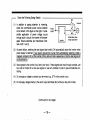
Check the Following Design Details
(1) In addition to paying attention to miswiring,
check the commercial power source selector
circuit shown In the figure on the right. If undesirable application of power voltage occurs
through such a circuit, the inverter will be damaged. Ensure electrical and mechanical interlock of MC 1 and 2.
Interlock
Power
supply
W
Undesirable power
(2) At power failure, retaining the start signal (start switch) ON automatically starts the inverter when
(3) Input signals to the control circuit are at low level. If these signals are input through contacts, use
two units of contact for at low level signals or use twin contacts in order to prevent defective contacting.
(4) Do not apply a voltage to contact input terminals (e.g., STF) of the control circuit.
(5) Do not apply voltage directly to the alarm output terminals (B,C) without a relay coil or lamp.
(Continued on next page)
-18-
I
h
(6) If you connect an open collector output such
as a sequencer directly to the inverter input
terminal, make sure that undesirable current
may not be generated.
e
r---.-l
ProtectivT--;-q
diode
,
n
Measures
(1) Insert a diode for preventing undesirable
current.
coupler
u v
MELSEC
(2) Use an independent output unit.
Sequencer MELSEC-A
(example: AY40A, etc. )
-19-
L
.
.
,
.
.
Inverter
Wlrlng of Power Supply and Motor
Terminal block '
Power supply
The Dower s u ~ ~ must
l v be connected to R. S. and T.
Never connect'it-to U, V, and W, or the inverter will be
m
--
e sequence, is not important.)
Connect the motor to U, V, and W.
With wires connected as shown in the above illustration, turning on the forward rotation switch (signal) will
rotate the motor counterclockwise viewed from the
loading shaft side.
Discharge resistor for
brake
(option)
Notes:
1. Terminal block
Terminal arrangement
as shown on the previous page.
Screw size .....M3.5 screws (FR-Z024-0.1 K to 1.5 K), M4 screw (FR-Z024-2.2 K,3.7 K)
Terminal specification
see description of terminal specification (page 120).
2. Using wire size
See Selection of Peripheral Devices (page 133).
3. The shape of terminal block differs according to inverter capacity.
4. Motor overload protection must be provided in accordance with the National Electrical Code.
5. This drive is not intended to provide overspeed protection.
.....
.....
-21
-
h
_ ~ _
~-
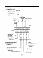
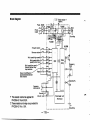
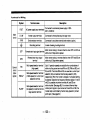
Wlrlng for Control Clrcult
Frequency meter
This resistor is not required
when meter is calibrated
with the parameter unit
Parameter C1
I C a l i b rtentlometer
a t i o np
o
l
1K 2W
Frequency reference
potentiometer
-Frequency reference
Alarm output
(Ib contact)
t t I I i I VI
c
B
Terminal block
SE
RUN
RL
I
I
I
Operation status output
(RUN: in operation)
(SU: up-to-frequency)
(FU: Frequency detection)
(See page 93 and 94.)
Multi..speed selection (low speed) or selection
of the external thermai relay input
(See page 80 and 91.)
io
SD
FM
RM
. . I.
2
5
RH
STF
1
I
SD
SD
4
STR MRS RES
1
1
.
1
f t t t f t t
'jLL
Multi-speed selection (middle speed) or selection of the current input
(See page 91 and 92.)
Multi-speed selection (high speed)
Reset
Output shutoff or selection of second
acceleration /deceleration
(See page 81.)
Start reverse rotation
Start forward rotation
-22-
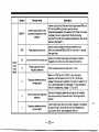
Notes: 1. Terminal block
Terminal arrangement as shown in the above illustration (two-row).
M3 screws
Screw size
2. Input and output specifications for terminals marked with an asterisk "I may be
controlled via the parameter unit.
3. Three terminals named SD are connected in the inverter.
.....
.....
- 23 -
h
,
.*_
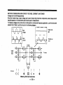
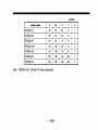
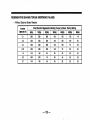
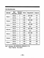
FOR USE WITH SINGLE-PHASE POWER SUPPLY
When the inverter is used with the single-phase power input, the ripple current of the capacitor
Increases as compared to the use with the three-phase power input, raising the temperature of
the converter and capacitor. Hence, the inverter cannot be used with a rated output single-phase
power supply but may be used with the single-phase power input which is lower in output current
than the three-phase power input.
*
Type
Rated output
current (A)
FR-2024
-0.1 K
FR-2024
-0.2K
FR-2024
-0.4K
FR-2024
-0.75K
FR-Z024
-1.5K
FR-Z024
-2.2K
FR-Z024
-3.7K
0.4
0.6
1.5
3
4
5
7
Rated output
voltage
Three-phase,200 to 230VAC, 50/60Hz
Power supply
voltage
Single-phase,200 to 23OVAC, 50/60Hz
Power supply
capacity (kVA)
AC input current (A)
0’4
1.1
0.8
1.5
2.5
4.5
5.5
9
2.4
4.5
7.6
11.2
12.9
17.4
-24r
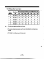
Notes on Use wlth Slngle-Phase Power Supply
*
(1) The single-phase power supply must be connected to the power supply side terminals R and
of the inverter.
S
(2) The inverter must be used with the power supply of sufficient power supply capacity. If the
power supply capacity Is small, the output voltage will be varied greatly by the load.
Single-phase AC power supply
200 to 230V
NFB
Motor
50 / 60HZ
Circuit Example1
-25-
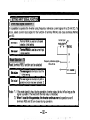
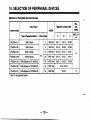
7. PRE-OPERATION SETTINGS
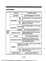
Principal parameters and descriptions are as follows. Set these parameters according to operational
requirements.
Setting Method: Use the parameter unit for setting parameters. See page 30 for
descriptions of settings.
-
D-crlptlon
Parsmetere
Related Functlons
Set the frequency reference voltage signals input across terminals 2 and 5.
DC 0-10 V
DC 0 5 V
Set parameter number 73 to 1.
Frequency reference signal
Select 5V or 1 O V
Set parameter nurnber 73 to 0.
4""
0-10 v
Input selection 5 V/10 V (parameter number 73)
II *
The inverter is set as
shown above when it
isshipped.
Note: Be sure to select the 0-5 VDC input if you connect a freauencv reference Dotentiometer (variable resistor).
(Continued on next page)
-26I
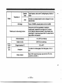
Parametem
Maximum output
frequency
Maximum
frequency
Minimum
frequency
Related Functlonil
Deecrlptlon
Set this parameter when you operate the inverter with a value
other than that set when the inverter is shipped. See below for
control variables set at shipment. If it is necessary to obtain output frequency higher than 60Hz, the maximum output trequency
reference must be changed.
‘(Control Variables Set at Shipment)
’ Voltage signal .....
60 Hz at 5 VDC (or 10 VDC)
’ Current signal .....
0 Hz at 4 mADC, 60 Hz at 20 mA
PU operation .......
up to the maximum frequency of
120 Hz
Frequency for input
voltage signal of 5 V
(parameter number 20)
Frequency for input
current signal of 20 mA
(parameter number 39)
Maximum frequency at
PU operation
(parameter number 1)
Set this parameter only when you set the maximum or minimum
-frequency.
* Maximum frequency
Although it is possible to set the maximum frequency within the
range indicated above, the inverter may not operate correctly if
the maximum frequency is set incorrectly.
Note:lf the minimum frequency is set, the motor will run at thc
minimum frequency by just turning the start signal on.
*
(Continued on next page)
-27-
(parameter number 1)
Minimum frequency
(parameter number 2)
A
Electronic thermal
relay
Acceleration/
Deceleration time
Descrlption
Related Functions
Set the relay in accordance with the rated current at the base
speed of the motor.
Note:Operation characteristics, are based on operation with i
standard squirrel cage motor. They are not applicable ti
special motors. If you use a special motor, mount an extei
nal thermal relay to protect your motor. This also appliei
to mutiple motors.
' Electronic thermal relay
If you perform acceleration/deceleration operation with a time
other than the value set when the inverter is shipped, change
the acceleration/deceleration time.
* Acceleration time
Value set at shipment: 5 sec.
Note:The set value is the time from start to the maximum outpu
frequency stated before.
-28-
(parameter number 9)
of applicable
load
(parameter number 14)
' External thermal relay
Input selection
(parameter number 46)
' Selection
(parameter number 7)
' Deceleration time
(parameter number 8 )
Second acceleration
/deceleration time
(parameter number 17)
' Second deceleration timc
26
(parameter number 47)
In order to monitor the output status accurately, calibrate the frequency meter before operation. Use of
the parameter unit allows precise adjustment. (See page 64 for calibration procedures.)
- Changing usage of an inverter (Previouly set up)
Because such an inverter might have parameters set previously according to a specific operation, reset
parameters before operation (reset parameters to values set when the inverter was supplied by
Mitsubishi).
The inverter may be factory reset on the parameter unit. (See page 61 for initialization.)
Note, however, that the parameters that follow may not be initialized even if you all clear
parameters using the parameter unit. Read each control variable and change it to a needed value.
' Parameter number 20
' Parameter number 39
*
'
Parameter number
Parameter number
Parameter number
Parameter number
C-2
C-3
C-4
C-5
'frequency
'frequency
'frequency
'frequency
'frequency
'frequency
for 5 V input signal'
for 20 mA input signal'
reference voltage bias'
reference voltage gain'
reference current bias'
reference current gain'
- 29 -
+
8 . OPERATION
Check Points before Swltchlng Power On
e
-
Check that the power lines are connected to terminals R, S, T. Also check that terminals are tight.
Check that the source voltage meets the rated value, and is not exceeding the specification of the
inverter. (See page 113 for specifications.)
Check that the setting of the maximum output frequency is within the load (machine) specification
range. (See page 78 for setting conditions.)
Check that short-circuit or ground fault do not exist in the output circuit or sequence.
B a s k Operating Procedures
After the inverter has been wired, follow the procedures on pages 31, 32 and 33 to check that it operates
correctly.
-30-
- Operation with External Signals
Example of setting frequency with
I
h
a voltage signal
Switch power on.
(The power indicator lamp is lit.)
4
Start
Turn the start switch on. (Short-circuit across terminals
STF and SD or STR and SD.) ' 1
I
Acceleration
Constant
4 speed
I
Slowly turn the variable resistor (frequency reference potentiometer) clockwise to the maximum position.
Deceleration
Slowly turn the variable resistor (frequency reference potentiometer) counterclockwise to the maximum position
'2,'3
stop
Turn the start switch off. (Open across terminals STF and
SD or STR and SD.) * 1
-31
-
I
I
- Operation with the Parameter Unit
Using the parameter unit.
Switch power on.
(The power indicator lamp is lit.)
I
Selecting the PU
operation mode
I
Setting output
frequency
i
I
Start and
ation
Frequency
change during operation .4
and
stop
Press the PU OP key to select the PU operation mode.
(The indicator lamp next to the PU OP key is lit.)
Enter the frequency value with which you want to operate
the inverter using the numeric keys, then press the WRITE
key, or hold down
or [Eluntil desired output frequency
is reached.
1
Press the FWD or REV key.
After pressing the PU OP key, enter the frequency value to
which you want to change, with the numeric keys, then
press theWRlTE key, or hold down [El or
until the desired output frequency is reached.
Press the STOP key. '3
-32I
Notes:
1.
2.
3.
4.
The inverter will not start if both forward and reverse rotation switches are turned on. If both
switches are turned on during operation, the inverter will decelerate and stop the motor.
If the start switch is turned off with the variable resistor turned clockwise to the maximum
position, the inverter will decelerate and stop the motor.
A high pitch sound is generated just before the motor stops, this is normal. The sound is
generated because the DC dynamic brake is in operation.
If the parameter unit is removed from the inverter during operation, normal operation wiii
continue, however, the motor cannot stop, therefore, do not remove the parameter unit
during operation.
,-
F
-33-
Using both External Signals and PU Operatlon
The 2024 inverter permits use of both external signal and PU operations. The details are as
follows:
The start signal is controlled externally, while the output frequency is set on PU.
1. To select this configuration, first, set parameter number 79 'operation mode
selection' to 11. (See page 51 and 52 for detailed procedures.)
2. After turning the start switch on, output frequency is set on PU during operation.
(See page 44 and 45 for detailed procedures.)
Notes: 1. The external frequency reference signal or PU forwardlreverse rotation and stop keys
are not accepted.
2. The operation mode lamp indicates PU operation. The external signal operation mode
cannot be selected.
3. If the start switch is turned on, the inverter is not switched to the monitoring mode
automatically. To monitor data, press the MONITOR key.
Start switch
I
Inverter
-34-
I
-
The start and multi-speed selection signals are externally controlled, while setting of multispeed is done by using the PU.
When the inverter is supplied, setting allows for this configuration.
1. After turning the start switch on, select multi-speed signal needed for operation
(short-circuit terminals RH-SD, RM-SD,or RL-SD).
2. Control multi-speed frequency on PU during operation.
If you selet high speed (short-circuit RH and SD), for example, a change in value of parameter number 4 'third speed setting (high speed)' alters speed during operation. (See page 48
and 49 for detailed operations.)
Note: Control variables of multi-speed other than those in-operation, may be changed during
operation.
Start switch
q
Inverter
M
- 35 -
The output frequency is controlled externally, while start/stop is controlled using.the PU.
1. To select this configuration, first, set parameter number 79
'operation mode selection' to 12. (See page 43 and 44 for detailed operations.)
2. While inputting output frequency (analog or
multi-speed selection stated above) signal externally,
runlstop is controlled by the FWD/REV and STOP key on
PU.
Notes:
1. The start terminals (STF, STR) on the inverter are
disabled.
2. The operation mode lamp indicates PU operation.
The external signal operation mode cannot be selected.
3. When not in the monitoring mode, the PU display
shows the frequency corresponding to the external frequency setting signal. Note that this frequency is not displayed unless the PU OP key is
pressed.
4.
i
1
d
Inverter
10
2
Frequency reference
potentiometer
1-1
Current input
selector
Inverter
The inverter may also be started by pressing the FWD or REV key of the PU, with the
external frequency setting signal set to 0, and then increasing the frequency setting
signal. (Note that O.01Hz is displayed when the set frequency is called by pressing the
PU OP key after the FWD or REV key of the PU has been pressed.)
-36-
.
.
In-operation Check Points
that the motor rotates in the correct direction.
Check that the motor does not generate unusual noises or vibration.
Check that the pointer of the frequency meter swings smoothly and correctly.
Check if the ALARM lamp lights, and the inverter stops (inverter trip).
See page 109 and 110 for causes and measures.
-37-
h
9. How to Use the Parameter Unit
Parameter unit, model FR-PUOI, is attached to the inverter (FR-Z series), or connected to the inverter with
the cable (option). The parameter unit permits the operator to set (read and write) various control variables
(parameters), and to monitor operational status and alarm messages through its readout.
In this manual, parameter unit FR-PUO1 is abbreviated as 'PU'.
-38-
A
‘R-PUOI PARAMETER
MOUNTING SCREW
By loosening two screws, the unit
can be separated from the inverter.
DISPLAY(READ0UT)
Frequency, motor
control variables, alarm message,
etc. are displayed by this 7-segment 4-digit readout.
VARIABLE INDICATOR LAMP
0
2nd or 3rd group function
key (2nd)
0
0
Control variable to be monitored (frequency, motor current, etc.) is indicated.
0
L OPERATION MODE KEYS
Press this key after pressing the
key to read or change (write)
con rot variables for the 2nd group
Operation mode can be selected
from: operation by the parameter
unit, operation by external signals,
readlwrite of control variables, monitoring frequency, motor current,
alarm messages.
Note: The parameter unit is abbreviated as ‘PU’
9
selected by
KEY after this
4
.b
SHIFT KEY
Variable (frequency, motor current,
alarm message) to be monitored is
shifted or 3rd group function is seIected.
FREQUENCY ADJUST KEYS
Whilst it is held down, frequency continuously increases or decreases.
4
CLEAR KEY
If incorrect key is pressed during
setting, it can be cancelled by
pressing this key.
FUNCTlONlNUMERAL KEYS
OPERATION KEYS
Direction of motor rotation can be selected and operation can be
stopped.
-I
L
Parameter No. of 1st group function and
value or frequency can be specified.
- 39 -
I
J
READlWRlTE KEYS
Variable setting can be read
h
10. INSTALLATION
The PU can be attached directly to the inverter, or connected to the inverter with the approved cable for
remb,te+in#aH$tion~on
an enclosure or control with the parameter unit held in the opetator’s hands. It can be
attached Waonnbetw even when the Inverter is in-operation.
DLrset Attachment to Inverter
Attach PU to the inverter front cover for use (it is electrically connected through the plug and
receptacle).
For Ffivetterswithout PU, replace the accessory cover on the inverter front cover.
I
o
(1) Connection
Engage the plug of PU with the inverter receptacle and
gently press the PU against the inverter.
(2) Securing the PU in position
Lightly tighten two screws to secure the PU in position.
- 40 -
Remote lnstallatlon Uslng the Approved Cable Connector
In addition to attaching PU to the inverter, it is possible to install it to an enclosure or to control it
held by hand for adjustment or maintenance. In this case, use the approved cable (option) to
connect PU and the inverter.
(1) Connection
Plug one end of the cable into the receptacle of
inverter, and the other end into PU. When plugging, fit
the guides to the grooves. (See the illustration on the
left.) (Improper connection may damage the inverter.)
(2) Locking of Plugs
The plug on the inverter side should be locked with
screws as shown on the left. On the PU side, secure
the cable so that the cable cannot be disconnected by
its own weight.
a:::::
Fit the guides
the grooves
to
Note: The extension cable, must be a Mitsubishi type, and is available as an option.
-41
-
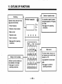
11. OUTLINE OF FUNCTIONS
Selection of operation mode
Monitoring
It is possible to select the external signal operation or PU operation mode.
See page 43 for operating
procedures.
Operation status and alarm message can be monitored.
Output frequency
Direction of motor rotation
Motor current
Operation mode
Alarm information
See page 55 for operating
procedures
-I
Motor control
The motor starts or stop or output frequency can be set by key
Operation on PU.
Setting of control variables
Jog operation is also available.
See page 51 and 52 for
Additional control variables can
be accessed and changed.
See page 51 and 52 for
operating procedures.
operating procedures.
I
1
-42I
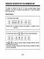
12. OPERATION
Selecting Operation Mode
How to Select Operation Mode:
1 . Operating the Inverter with External Signals (External Signal Operation)
When the inverter is supplied, it is set to this operation mode (when power is turned on, external
signal operation function), so it is not necessary to select operation mode on PU.
To select the PU operation mode from the external signal operation mode, press t h e m key.
2. Operating the Inverter with the Parameter Unit (PU Operation)
Press t h e p key to select the PU operation mode.
To select e external signal operation mode from the PU operation mode, press t h e m key.
3. Operating the Inverter Using both the External and PU Operation Modes To control the inverter
using the external and PU operation modes, for example, the start signal is input externally and
output frequency is set on PU, set parameter number 79 to 11 or 12. Such operation is available
only by this setting. See page 26 for detailed operating procedures.
-43-
,
Press the
key.
ul
Press the
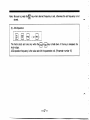
How to Set Operation Mode
L
PU
key.
I
1
It is possible to set only one mode of operation using either external signal or PU oparation.
When power is turned on, the set operation mode is selected, and selection of other operation
mode is prohibited.
-44-
I
Note: 1. Caution at changing operation mode
Operation mode cannot be changed when the start signal is on (STF-SD or STR-SD is
closed).
2. Caution for removing PU during operation
In the PU operation mode, do not remove PU during operation. The inverter will stay in
operation even if PU is removed. In that case, the operator cannot stop the inverter from
operating the motor.
-45-
OPERATING THE MOTOR WITH THE PARAMETER UNIT
The operator can startlstop the motor with PU, without any external frequency reference
potentiometer, or start switch. JOG operation is also available with PU. Follow the key operation
below to control the motor.
Operating Procedures
Frequency setting .....By repeating this procedure during operation, it is possible to vary the
rotation rate.
The increase (or decrease) of frequency is slow initially, after the key is pressed, but increases
as the key is held depressed.
-46-
Note: Be sure to press t h e m key when desired frequency is set, otherwise the set frequency is not
u
stored.
The motor starts and runs only while the
motor stops.
or
key is held down. If the key is released, the
El0
WD
REV
JOG operation frequency is the value set with the parameter unit. (Parameter number 15)
-47-
h
To return to external signal operation, press the
key, then press the key after the motor has
stopped.
(If the external signal operation cannot be selected, see page 69 and 70.)
(4) Method to Vary Speed with PU during Multi-speed Operation.
Operating procedure (1) or (2) on page 51 and 52 permits such variation. Note, however, that
pressing the
key is unnecessary.
Example of Operation
Example where 60 Hz is set for desired output frequency (from start to 60 Hz)
*
Set to 60 Hz
I
I
Stari
I
stoa
I
f
cation
1
1
"
'
'
I
I
-48I
,
.
I . i
I
*
Example where speed is changed during operation (from 60 Hz to 30 Hz):
h
Note: Direct setting of output frequency is impossible while the MONITOR mode indicator lamp is lit.
To set output frequency, press the PU key to cancel the MONITOR mode.
Ll
'
JOG Operation
Indication
I
o
i
a
a
i mlt
X o o k
X
I
-49-
I
Notes: 1. The JOG mode cannot be selected while the motor is in operation. Press the
key to
stop the motor, then select the JOG mode.
2. To cancel the JOG mode operation, press the q k e y .
3. Desired frequency and acceleration/deceleration ime (acceleration and deceleration times
are the same) for the JOG mode operation can be set by specifying the corresponding
parameter (control variable). (See page 90.)
When the inverter is shipped, the JOG frequency and acceleration/ deceleration time are set
to 5 Hz and 0.5 sec., respectively (it takes 0.04 sec. for increase of frequency up to 5 Hz).
4. If the motor does not start, check the starting frequency.
*
(m
When the motor is started by pressing the start key
o r m ) , the MONITOR mode is
automatically selected and output frequency is displayed.
While the inverter output is on (motor in rotation), the mode indicator lamp just above the
key
flickers (the same occurs during DC dynamic brake operation).
SETTINGS OF CONTROL VARIABLES (PARAMETERS)
The inverter has a variety of control functions. It is possible to choose individual parameters to alter or
check control variables.
The parameters(contro1 variables) are factory-set to run a standard AC induction motor, therefore
parameters should only reguire adjustment to suit individual application requirements.
Such as: AcceVDecel rates or min/max frequency are grouped into three categories, from 1st to 3rd
functions.
Setting procedures that follow differ according to this classification.
-
Setting procedures
(1) Setting of 1st functions (parameter numbers 0-9)
most often used.
.....These are
main function and are the
r-------I------------I------~----------------------
Parameter name (abbreviations) are indicated on the numeral keys (0-9).
-551
-
L
(2) Setting of 2nd functions (parameter numbers
applications.
(3) Setting of 3rd functions
lo-) .....These
are used in advanced
.....Calibration
*' Desired parameter may be called by pressing t h e B key several times. See page 49 for details.
To read a set value:
In the above procedure, press the
(Example)
READ
key instead of the
p]
key without entering a set value.
(The case of 2nd function)
To end or cancel settings:
To control the motor with PU at the middle of setting, or when settlng is complete, press the
-52-
key.
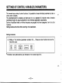
Examples of Operatlon
h
( 1 ) Setting of 1st Function (acceleration time setting)
Solsotton of
1st tunctlon
Key
Indi-
cation
1-gz;
0
;.,
;.0: /ov
Settlng of
eccelontlon time
.....To change from 5 sec. to 10 sec.
Read premnt
Change to
value
10 Sec.
mm
z
lJ
Write
p
J
*
l
W]rr-pTq m
lpl.11
(5 sec.)
Initial setting
Alternate
(1Osec)
Note: When another 1st function is to be set after setting a 1st function, the new desired arameter
can be called by just pressing the corresponding parameter key, so repressing t h e b key is
unnecessary.
-53-
/-.
(2) Setting of 2nd function (frequency reference for JOG operation)
Setting of
2nd funct'on
Of
frequency for
JOG operation
Read present
value
.....To change from 5 Hz to 10 Hz:
Change to
10 Hz
Write
Indication
Note: 1. A dot is placed after ,!D,-when the 2nd function is selected, ex. ( i-7 ,-.,)
2. When another 2nd function is to be set after setting a 2nd function, the new desired
parameter can be called by just pressing the 2nd key and specifying the parameter number,
so repressing the
key is unnecessary.
0
*
If changing parameter or reading is impossible:
See page 71 when an error message is displayed and a new value cannot be written.
-54-
MONITOR
Conditions of load such as output frequency and motor power, and information about activated
protectlve function at occurrence of an abnormality can be monitored with PU (by segment display and
LED lamps).
Type of Yonltored lnlotmatlon
I
I
I
monnored
Information
1 I
Unlt
Output frequency
Hz
Output current
A
Engineering Display Unit
Direction of rotation
I
I
-
In-operation
lndlcator devlce
Dleplay/operetlon/se~lng
In brief, etc.
I
Indicator
lamp
IVaJa;ble
indicator
I
In the MONITOR mode shift the display information with the
key
Readout and
variable indicator
lamp
Operation mode
indicator lamps
External signaVPU operation
1
I
I
Switched from the monitoring of the output frequency when
the function number 37 is set.
The lamp is lit at forward rotation and is flickering at reverse
rotation.
I
I
The lamp above the operation mode key corresponding to the
selected mode is lit. When the motor is running, the lamp
flickers, when stopping, the lamp is just lit.
MONITOR mode
Setting mode
I
JOG mode
I
-
IReadout
IIf the JOG meration mode is selected, 'JOG' is displayed.
-55-
I
Variable indicator lamps
Readout (7-segment 4-digit LED)
/-
Control variable to be monitored is
indicated. All lamps are turned off
when alarm information is on the
readout.
\
Operation mode indicator
/lamps
When an operation mode key is
pressed, the corresponding lamp is
lit.
/
Parameter Unit
-56-
Operation mode keys
lndlcator Lamp in the MONITOR Mode
In this manual, the variable indicator lamps are described in the following layout.
;e:is a "lit" lamp, and 0is an extinguished lamp. The same is applicable to the operation mode indicator
lamps.
lndlcatlon
Descriptlon
Frequency is displayed.
0 Hz
0A
Motor current is displayed.
0V
Not used.
If the stall preventionfunction is activated during MONITOR mode, all
MODE lamps except that selected flicker. If the motor is in forward or
reverse rotation, these lamps are lit or flicker, respectively.
Note 1: The engineering display unit is displayed when the function number 37 is set to any value
other than 0.
-57-
Example of Operation
*
Output frequency, motor current (constant), alarm condition (checking)
Motor current
Output frequency
Alarm condltlon
c 0
/
'do
'
/
I
-
A
'
ov
(6.5A)
(60 Hz)
Note: By pressing the
0 0
HZ
(Returns to the latest alarm.)
L7
SHIFT key when an alarm condition is indicated, the output frequency at the
time of the alarm IS isp ayed.
To check the stored alarm information:
Up to four alarm codes are stored. To check them follow the procedure below in the above alarm
condition displaying status.
I
Fl2nd latest alarm
................-
~ I - ~ I R E A D - - -................
- - --/ * /
READ
3rd latest alarm
Oldest alarm
-558-
(Returns to the latest alarm.)
I
Notes : 1. To erase an alarm code:
With an alarm code displayed, press the
@ key,
the
A
displayed code will be erased from memory, and the next code
will be displayed.
2. To check operatlon
At Occurrence of an alarm, the parameter unit automatically
conditions immediately
displays the activated protective function. In this condition if
before Occurrence of an
you press t h e m key (without resetting), output frequency
alarm:
is displayed. Thus it is possible to check output frequency
immediately before the alarm Occured. Motor current will also
be checked similarly, but these values will not be stored.
-59-
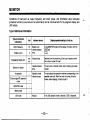
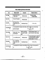
Dlsplay
--. Alarm
If failure occurs
during operation of the inverter, an alarm code is automatically displayed on the PU
readout as follows (See page 124 for details):
Code
DIaplay
c
1-1
/
cI -
EOC1
I E :2 I
I
c
L
1-1
I-
c
-?
Dwrlption
1
EOC2
EOC3
Inverter output current exceeded the overcurrent limit during acceleration.
I
I
inverter output current exceeded the overcurrent limit during constant-speedoperation.
Inverter output current exceeded the overcurrent limit during deceleration.
I
1
EOVT
Braking regenerative power from motor exceeded the regenerative overvoltage limit.
f-:1
I-/
1-1 1-1 II-
1
I-
1- (-1 1-1
1- I 1 1 I
Electronic thermal relay in the inverter was activated (current is below 150% of preset
current).
1’,
1-
I- I-/ II I 11
Electronic thermal relay in the inverter was activated (current is over 150% of preset
current).
c.
L
1-/
c
L
E. BE
Brake transistor in the inverter fault detection.
- 60 I
,
I
Dlaplry
Code
:/
I 7 /-I I -
1-
1-1 I I /
EOHT
1:
1-
1-1 1-
1-1 I
1
1I
1-
7 I:/
1-1 I
External thermal relay was activated.
Stall prevention function was activated during constant-speed operation and stopped the
I-
I
I E . a’1 1
I
De6crlption
L
E.PE
I-
EOPT
I
I
Data memory in the inverter and corresponding to parameter number is corrupted,
Indicates that the retry function has been activated or any error other than the error selected
by the retry selection has occurred and stopped the inverter.
-61
-
.-
Characters Appearlng In Readout
The alphanumeric which appear in the readout are listed below.
Letter
Dlsplay
- 62 I
~~~~~~~~~~
It is possible to reset (initialize) control variables to those set when the inverter is supplied except for
some parameters. This procedure is called ’ALL CLEAR’.
Operating procedure
1-
When writing is complete,
is displayed and flickers.
Note : The following control variables are not initialized through the all clear operation stated above.
~~~~
Parameter number
‘20
‘39
c-1
c -2
c-3
c-4
c-5
~~~~
~
~
~
Parameter name
Frequency for 5 V input signal
Frequency for 20 mA input signal
Frequency meter calibration
Frequency reference voltage bias
Frequency reference voltage gain
Frequency reference current bias
Frequency reference current gain
*These control variables set the maximum output frequency using external signal operation, and also
are reference frequencies for acceleration/deceleration time. After carrying out ALL CLEAR, check
these values and reset to optimum values.
- 63 -
h
FREQUENCY METER CALIBRATION
It is possible to calibrate any frequency meter connected to the frequency meter connection terminals,
FM and SD on the inverter, by operating the PU. If it is a digital indicator, pulse train signal frequency
may be adjusted.
Preparation (1) Connect the frequency meter across terminals FM and SD on the inverter. (Pay
attention to polarity matching.)
(2) If a calibration resistor has already been connected, remove it or adjust it so that its
resistance reads zero.
Frequency meter
Inverter
Calibration
resistor
- 64 -
Operatlng Procedure
(Set to 60 Hz when the
inverter is shipped.)
1. Operate PU to set the
frequency for meter fullscale reading. (*)
2. Select the meter calibration
mode.
3. Calibrate the meter.
of the frequency meter,
When the meter has been calibrated, press the WRI
key.
'The motor need not be connected.
Note: If a signal relative to magnitude of motor current is to be output from the FM terminal (see page
95),install a calibration resistor at the position shown on the previous page. Output of the FM
terminal is not adjusted with the above procedure.
-65-
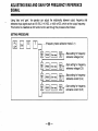
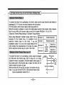
ADJUSTING BIAS AND GAIN FOR FREQUENCY REFERENCE
SIGNAL
,
-.
Using 'bias' and 'gain', the operator can adjust the relationship between output frequency and
leference input signals such as 0-5 VDC, 0-10 VDC, or 4-20 mA DC, which set the output frequency.
This function is classified as 3rd function and is set through the procedure that follows:
SETTI NO PROCEDURE
r
lwmp-lpJ7
.....(Frequency meter calibration mode C-1)
,..Bias setting for frequency
reference voltage ((3-2)
...Gain setting for frequency
1'
1
I.
I
reference voltage (C-3)
...Bias setting for frequency
reference current (C-4)
..Gain setting for frequency
reference current (C-5)
- 66 -
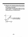
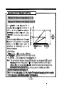
of Adjustment
-Example
Bias setting for frequency reference voltage .....when the reference voltage is 0 V, the output
-
frequency will be 10 Hz.
I
Output frequency
60Hz
F
-67-
Note: Setting should be made with voltage across the frequency reference input terminals 2
and 5 using 5 V (or 10 V) or with input lines disconnected. (When setting characteristics
shown in the illustration on the previous page.)
If a voltage is being applied, output frequency relative to that voltage is set. In the above
procedure, for example, if 1 V is being applied across terminals 2 and 5, output
characteristics become as shown in the illustration below (solid line).
10 Hz
/
?
,
. A
0
1'v
If you want to set 0 Hz against 1 V
input, set 0 Hz in the above procedure.
I
5'v
-68-
CAUTIONS FOR PU OPERATION
Pay attention to the following points so as to avoid incorrect setting or entry of a wrong value during
PU operation.
Cautlona
Operation
Motor control
by PU Operation
la
Becomes effective only after pressing the PU key.
When PU is in the monitcr mode (when the indicator lamp above the MONITOR key is lit),
setting the ou ut frequency is impossible.
Press the PU key to leave the monitor mode and enter a new value.
LJ
An error indication (Err.) will be displayed, or the value you entered will not be written under
the conditions that follow :
(1)
When you have entered a value exceeding the maximum or minimum frequency
(setting value for parameter number 1 or 2) :
(2) When prohibition of parameter entry is effective (parameter number 77 is set to 1) ;
(3)
When PU is in the external signal operation mode (the indicator lamp above the
key is lit) :
(4)
When PU is in the monitor mode (stated above). (Note, however, step setting is
possible.)
M
JOG Operation
(1)
The JOG Operation is not available when the motor is running.First, stop the motor to
perform the JOG Operation.
(2) If the motor does not start, check whether the JOG Operation frequency is lower than
the start frequency (parameter number 13).
-69-
Opmtlon
Writing values
Ceutlonr
1.
Writing is effective only when PU is in the PU Operation mode, accordingly, it is ineffective
in the external signal Operation mode. (Set values can be read in either mode.)
2.
Writing is impossible when the motor is running. First, stop the motor to write values. The
following parameters, however, may be written even when the motor is running.
3.
Writing values
1
(1)
Multi-speed setting (speed 1-7) ...... Parameters number 4-6, 24-27
(2)
PWM mode ...... parameter number 10 (only in the PU Operation mode)
Setting values cannot be written under the conditions that follow (an error message will be
displayed) :
(1)
When PU is in the external signal Operation mode;
(2)
When the motor is running (except the above two parameters):
(3)
When prohibition of parameter entry is effective;
(4)
When a number not on the parameter list is selected:
(5)
When a value exceeding the setting range i5 entered;
(6)
When a value exceeding the maximum or minimum frequency is set.
When an error message is displayed, press t h e [ E ] k e y , or repeat the procedures from
the first sten
- 70 I . 1
Operation
Reading values
Monitor
Common -Operation
mode.
Maximum number of
I
Cautlonr
1.
It is possible to read the set values for the 1st and 2nd functions in both PU and external
Operation modes.
In addition, reading is possible if the motor is running.
2.
Reading the set values for the 3rd functions is possible only when the inverter is in PU
Operation mode.
1.
When the Operator uses the PU to control the motor, pressing the start key (FWD or REV)
after setting frequency automatically selects the monitor mode.
Selecting PU or external signal Operation
Pressing the PU key (or rn key) is not allowed for mode change under the conditions
that follow :
m m
digits stored and the
(1)
When the motor is running ;
decimal point.
(2)
When the start signal (across terminals STF and SD or STR and SD) for the external
signal Operation is ON.
(3)
When Operation mode (parameter number 79) is set to PU operation or external
signal Operation.
Switching on the power of the inverter after switching it off or resetting (across terminals
RES and SD) the external Operation mode. (Initial setting)
The maximum number of digits for entry is four. If this is exceeded, the first digit is
disregarded. (Example : Pressing 12345 will be set as 2345.)
Pressing. 1 for 0.1, as is done for a calculator, is regarded as 1, and the decimal point will
be disreaarded. Do not omit a 0.
-71
-
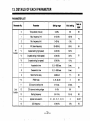
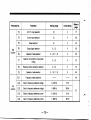
13. DETAILS OF EACH PARAMETER
PARAMETER LIST
-72I
'
Parameter No.
1
I
16
Jog acceieration/deceleration time
17
2nd acceIeratiotVdecelerationtime
18
19
Setting range
Parameter
I
I
High-speedmaximum frequency
Base frequency voltage
0,0.1-3600
initial eettttlng
S~C.
0,0.1-3600 sec., 9999
1
I
120-360Hz
Oto500V, 9999
I
I
page:
0.5 sec.
90
9999
81
120Hz
9999
1
I
78
84
20
Frequency a 5 V input voltage
1-360 HZ
60 Hz
78
21
Stall prevention level
0-200%
150%
88
Multi-speed setting (speed 4)
0-360 HZ,9999
9999
*25
Multi-speed setting (speed 5)
0-360 Hz, 9999
9999
‘26
Multi-speed setting (speed 6)
0-360
Hz,9999
9999
*27
Multi-speed setting (speed 7)
0-360 Hz, 9999
9999
29
Acceleration/deceleration pattern selection
0,1 , 2
0
82
37
Engineering display unit display
0,2, 4,6, 8, 10, 11 to 9998
0
101
39
Frequency at 20 mA input
1-360 HZ
60 Hz
78
42
Up-to-frequency sensitivity
1-1 00%
1 0%
94
2nd
*24
function .
91
h
Parameter
No.
Parameter
Setting range
lnltlal setting
43
Output frequency detection
0.5-360 HZ
6 Hz
44
Output frequency detection at reverse
rotation
0.5-360 Hz, 9999
9999
53
Retry execution count display erase
0
0
100
95
69
I
Refer to
page:
94
1
Parameter set by the manufacturer. Must not be set.
70
FM output terminal function selection
0,1
0
72
Current monitoring output gain
0-200%
150%
-74I
I
ParameterNo.
I
I
Parameter
Setting range
1
initial setting
I
73
5 V/10 V input selection
0, 1
0
77
74
Current input selection
0%1
0
92
75
Reset selection
0, 1
0
92
Output signal selection
0,1,2
0
93
79
Operation mode selection
0, 1,2, 11, 12
0
83
I I
Selection of prohibition of parameter
writing
2nd
function
76
77
- 75 -
I
O
Ig7
Notes : 1. Set values differ depending on inverter capacity.
2 . For parameters marked with a star, it is possible to change set values during operation. (Initial
setting)
3. Minimum setting step
Frequency ....................... 0.01 Hz. Note, however, if frequency is 100 Hz or higher, the
minimum setting step is 0.1 Hz.
Time ................................. 0.1 seconds. Note, however, if 0 is entered, 0.04 seconds is set.
Current ............................ 0.1 A
Yo ...................................... 1%
4. The set value of 9999 indicates that "the function is inactive."
.
.
.
.
-76I
SELECTING FREQUENCY REFERENCE SIQNAL (5 VHO V)
0-5 VDC
It is possible to switch the input (terminal 2) specification
according to the frequency reference voltage signal.
When you input 0-10 VDC, be sure to select appropriately.
I
I
Set value 0
Set value 1
1
0-10 VDC
common
i
For 0-5 VDC input
(initial setting)
I
For 0-1 0 VDC input
Frequency reference
potentiometer
10 (5 V only)
F
- 77 -
t
MAXIMUM OUTPUT FREQUENCY SETTINO
It is possible to set frequency for a
frequency reference signal of 5 VDC (or 10
VDC) or 20 mA from external equipment.
Accordingly, this is the maximum output
frequency in the external signal operation
mode.
Several accelerationldeceleration times can
be set for JOG operation or multispeed
setting is the time (ramp) taken for
acceleration or deceleration up to the
maximum frequency.
G
E.
fml
$
;
0 fm2
22
,O
P-J
------------
------ -----
FreqJenCy reference
signal
Outpu1
frequency
range
5 V(10 V) 20
mA
<initial Setting>
* Voltage signal .....60 Hz at 5 VDC (or 10 VDC)
Current signal .....0 Hz at 4 mA DC, 60 Hz at 20 mA DC
* PU operation .....Up to the maximum frequency of 120 Hz
Note: The set maximum frequency changes automatically if you change setting of 'gain for
frequency reference voltage signal' or 'gain for frequency reference current signal'
included in the 3rd functions (see page 43). Since this function has the same priority
level as that of 3rd function (C-3, C-5), priority is given to the latest set function.
This is to be set when running at 120 Hz or higher. The maximum frequency, parameter number
1 of the 1st function is automatically updated to this frequency.
-778I
SETTINO THE FREQUENCY LIMIT FUNCTION
Max. limit frequency
Min. limit frequency
Output frequency can be changed to desired
maximum andlor minimum frequency.
setting range
Frequency reference
signal
6
v(io v)
20 mA
Notes: 1. When performing an operation that requires setting of the minimum frequency limit, the
limit should be higher than the starting frequency (see page 85). The maximum frequency
limit may not be higher than 120 Hz.
2. When the minimum frequency limit is set, the motor will run at that frequency by switching
the start signal on.
Note: Set these limits only when you want to restrict higher or lower output frequency.
This parameter is set to prevent problems caused
by inappropriate reversing of motor rotation.
Note: If this selection is made, it prevents
forward or reverse rotation in the PU
operation mode as well as in the external
signal operation mode.
- 79 -
setttng
Dlrectlon of rotation
Both forward and reverse rotation
are available (initial settlng).
Reverse rotation is prevented.
Forward rotation is prevented.
I
,r-.
,
.
. ...
.
,
. .
..
.
.
When using Mitsubishi “constant torque motor“ that is
exclusive for the inverter drive, it is possible to set
electronic thermal relay for this motor. If you set
parameter number 14 to one of the values listed on the
right consider the characteristics of the load, the value
set for electronic thermal relay 9 is set for this motor.
setvalue
Constant
Set value
l1
Reduced torqueload
For
Set value 13
load
constant
Boost 0% at
reverse rotation
torque
elevation
Boost 0% at
forward
- 80 I
’
4ACCELERATlON/DECELERATION TIME SETTING I
The acceleration/deceleration time can be set to 0.04 sec.
or within a broad range from 0.1 sec. to 3,600 sec. The
acceleration time is the time (ramp) taken for acceleration to
the frequency (fm) set by the "frequency at 5 V Input voltage"
and
(see for
page
2nd14).
acceleration/
Time for acceleration
deceleration intime
the isJOG
similarly
operation
set.
Initial setting: 5 sec.
s
fm14
CL
;
f
3 0
; Acceleration
Time
Deceleration
time
time
If 0 is entered for acceleration time, 0.04 seconds is set.
Note: Time for S-shape acceleration/deceleration A (see the Illustration on the following page) is
the time (ramp) taken for reaching base frequency.
Selection of 2nd
acceleration/ deceleration time
r
contact
it is possible
point to
signal.
select
To2nd
do acceleration/
so, set the 2nd
deceleration
acceleratlonldeceleration
time by an external
time
0- MRS/RT
and close terminals RS and SD. Initial settlng : 9999 (Terminal MRSlRT
is used for output shutoff.)
To set deceleration time different from acceleration time : Set the
Inverter
acceleration time and deceleration time by parameter number 17 and
47, respectively.
Note: If parameter number 47 is set to 9999 (initial setting), acceleration and deceleration are
carried out in the same time set by parameter number 17.
-
-81
-
.
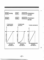
4SELECTING A
Set value 0
[Linear acceleration/
deceleration] (Initial
Setting)
C
C
E
L
E
R
It is the general
acceleration/deceleration mode in which
acceleration deceleration is linear up to
the frequency at 5 V input (fm).
A
~
~
ifm
:;f
output
Maximum
B
frequency
%G
o_s
t
Time
Set value 1
[S-shape acceleration/
deceleration A]
Set value 2
[S-shape acceleration/
deceleration B]
The acceleration/deceieration ramp is
steep where the motor output torque is
large and is gradual where the motor
output torque is small. The
acceleration/deceleration time may be
reduced.
Acceleration/deceleration show S-shape
characteristicsbetween output
frequencies 11 and f2. The time taken for
the acceleration/decelerationfrom 11 to
f2 is the same as that taken for linear
accelerationldeceleration.The S-shape
acceleration/decelerationB is
characteristically smooth.
-82-
,fb:
P
S f
o_€
Time
Base
frequency
OPERATION MODE SELECTION (EXTERNAL SIQNAL OR PU OPERATION)-
-/
1
h
i
The external signal and parameter unit operation modes are available for operation of the
inverter. Operation mode can be fixed to either operation mode, or both operation modes may be
used.
I
The parameter unit and external signal Operation modes are alternately used
value
(initial setting).
I
Set value 1
I Only the PU operation is available.
I
Set value 2
1
I
I
Only the external signal operation is available.
set
,'
Output frequency is set by the parameter unit. The start signal Is input as an
external input signal.
Set
12,
Output frequency is set by the external input signal. The start signal is input
from the parameter unit.
I
I
I
I
I
Notes: 1. It is possible to update values for this parameter number even in the external signal
operation mode.
*2. In this operation mode, output frequency setting and control of the start signal are
performed by using the external signal and parameter unit. When set value is 12,
output frequency is for analog signals and multi-speed setting.
3. Refer to page 30 37 for details of operation.
-
-83-
4
h
SETTING FREQUENCY FOR THE MOTOR RATED TORQUE (BASE FREQUENCY)
The base frequency (reference frequency at rated motor torque) can be set in accordance with
the motor ratina within the 2nd acceleration/deceleration time, parameter number 17 is set and
terminals RT a i d SD are closed. *
2nd acceleration1 deceleration
time selection
Base frequency setting range
-l-!
MRSIRT
Base frequency
I
Inverter
I
50
Note:
'1:
I
fO (base frequency) 3kO
Output frequency (Hz)
If the 2nd acceleration/decelerationtime, parameter number 14 (0 or 0.1 to 3600 sec.) is not set, this
function is not effective despite the 2nd V/F is set and terminals RT and SD are closed.
*2: At the setting of 9999 (factory setting), the maximum output voltage is the power supply voltage.
-84-
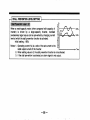
MOTOR TORQUE ADJUSTMENT (TORQUE BOOST)
Motor torque in the low-frequency range can be adjusted
to motor load.
Note: If the set value is excessively large, overcurrent
protection may be activated. It is possible to adjust
motor torque while observing motor current, using
the monitor function. The 2nd torque boost is
effective when the 2nd accelerationldeceleration
time 17 is set and terminals RT and SD are
closed.'
The starting frequency can be set in a range from 0.5 Hz
to 10 Hz.
frequency (Ht)
Output frequency
(H2)
a
d 0.5
Frequency reference signal
h
- 85 -
4SETTINQ APPLICABLE LOAD 1
It is possible to select output characteristics (V/F characteristics) that are optimum for the
application or load characteristics.
If you use the Mitsubishi constant torque motor, set values from 10 to 13 which are listed in the
right-hand table. By setting one of these values, it is possible to set electronic thermal relay
exclusively for the constant torque motor in the electronic thermal relay parameter number 9.
sa value
Output char.cteri.tlc8
0
Constant torque load (initial setting)
I l l
Reduced torque load
2
Elevation load (zero boost setting at reverse rotation)
3
Elevation load (zero boost setting at toward rotation)
10
Constant torque load
11
Reduced torque load
~
12
Elevation load (same as that of set value 2)
13
Elevation load (same as that of set value 3)
-86-
For the
constant
torque motor
(initial setting)
lset vaiue 10 I
pZiZGT1
p z q
or
boost
0
Set value 2
12 ....Wo
setting only at
reverse rotation
vl
boost
.
setting
,
only.
at
.~~
foward rotation
For reduced torque load
(fan, pump, e t a )
For constant torque load
(conveyor, carriage, etc.)
For elevation, constant torque load
100%
m
a
a
r"
->
Base frequency
Output frequency (Hz)
I
LI
a
a
0
0
Base frequency
Output frequency (Hz)
-087-
I
I
Base frequency
Output frequency (Hr)
When a small-capacity motor (when compared with capacity of
inverter) is driven by a large-capacity inverter, overload
(excessively large torque) can be prevented by changing current
level at which the stall prevention function is activated.
Initial setting : 150%
Notes: 1. Operating current ( O h ) is a ratio of the set current to the
rated output current of the inverter.
E
g
?
3. If the stall prevention Is activated, an alarm signal is not output.
- 88 -
DC DYNAMIC BRAKE ADJUSTMENT
Operating frequency
setting range
Accuracy of the stop position can be adjusted by setting
the DC dynamic brake torque (voltage), braking time, and
braking start frequency match the load.
DC brake
Notes: 1 , When the DC dynamic brake is not required, set
voltage
Voltage
brake time to 0.
2. If speed is decelerated by decreasing frequency
Operating time
reference signal voltage (or by pressing), the DC
dynamic brake starts operating at 0.5 Hz of output frequency. (initial setting)
3. Initial setting of DC dynamic brake voltage : 8%
Time
k
M
- 89 -
Time
SETTING FOR JOG OPERATION
1
Use of the parameter unit permits JOG operation. JOG
operation by external signal operation is not available.
lnitial setting : JOG frequency: 5 Hz
JOG acceleration/ deceleration time : 0.5
sec.
Note: Refer to page 46 for PU operation.
D
Time
, T o n b *
0
Reverse rotation
I
I
key
I
,
I
I
,
I
I
,
I
key
-90-
4MULTI-SPEED OUTPUT FREQUENCY SETTING I
I
1
By changing the external contact signal, each
speed can be selected (across terminals
RH-SD, RM-SD, and RL-SD). Each speed
(frequency) can be set ranging from 0 Hz t
360 Hz.
and
are not effective for this setting.
3
=
@l
Notes: 1. If speed 4 to 7 is set to9999 (initial
setting),
these speeds are not selected.
2. With 3-speed setting, if two or three
speeds are simultaneously selected,
priority is given to frequency of
lower signal.
7
me
Across
RH and SD
Across
Example: If RH and SD, and RL and SD are simultaneously turned on with high speed (RH)
and low speed (RL) set to 40 Hz and 50 Hz, respectively, 50 Hz will be selected.
3. Selection of the external thermal relay input makes the three-speed setting (low speed)
Invalid. To perform three-speed operation, set the function number 26. (RH RM)
4. When the multi-speed signal and external frequency setting signal are input, the
frequency setting for the multi-speed signal has priority.
-91
-
4
SETTING INPUT SIGNAL FUNCTION
I
It is possible to operate the inverter using frequency reference current signal (4 to 20 mA DC).To
do so, select current input signal for the function of terminal RM/AU and close terminals RM/AU
and SD.
Terminal RM/AU is used as multi-speed
I
Set value
,
Terminal RM/AU is used as current input
signal selection.
Reset (terminal RES) function can be selected.
I
The reset signal can be input at any time.
'1 (initial setting)
Set value
Set value
,
I
Current input
signal selection
RMIAU
I
Frequency reference signal
DC4-20 mA
I
-*
t
5
inverter
The reset signal can be input only after a
protective function has been activated. '2
Notes: *I.If the reset signal is input during operation, inverter output is shut off as long as the
signal is present. The electronic thermal relay is initialized.
'2. When 1 is set for this parameter, the inverter continues normal operation even if
terminals RES and SD are closed during operation.
-92-
4SELECTING OUTPUT SIGNAL FUNCTION I
Any one of "in-operation", "up-to-frequency", and "frequency detection" can be selected and
output as the open collector output signal (terminal RUNISUIFU).
- 93 -
-/
OUTPUT SIGNAL THRESHOLD LEVEL SETTlNd
I
Operation frequency
When output frequency reaches the operation frequency, an
output frequency value that shifts the level of output signal
can be adjusted in a range of k100% of the operation
frequency.
across terminals
The user can set an output frequency to be detected in a
range from 0 to 360 Hz.
When output frequency exceeds the set frequency value, an
output signal from terminals FU and SE is set to level L. If
output frequency is under the set value, output signal is set to
level H.
This feature can be used as a signal
for actuation and release of a mechanical brake.
With this function, it is possible to set a different actuating
timing with electromagnetic brake for reverse rotation (down)
from that for forward rotation (up) in applications such as
elevation. The initial value is 9999 that detects output
frequency of 6 Hz for both forward and reverse rotation.
su
and SE
6
Frequency t
be detectec
can be set e
Output signal
across
terminals FU
and SE
Forward
rotasion
detected 44
-941
.
Frequency to
be detected 43
Reverse
rotation
-1 SETTING AND ADJUSTMENT OF OUTPUT SIGNAL FOR MONITORING I
. ..... . . . .. .. . .. .. . . . . . . . . .. .
.
.
.
,
. .. . . .. . .
.
. .. .
..
.
Output terminal FM is used to connect an indicator that monitors
operating status. Output frequency or motor current (output
current) can be lndlcated by selecting either one.
I
Set value 0
Set value 1
I
Frequency to be detected. (initial setting)
t
I
Motor current (output current)
Output frequency
or motor current
. . .
.
If motor current is selected as the output from terminal FM, the
relationship between motor current and output signal can be
adjusted. Set current (%) against terminal FM's output of 1440 Hz.
Output frequency from terminal FM varies in proportion to the
current.
I
Set value
0-200
Ratio to the rated output current of inverter
(%)
~
Initial setting : 150%
t
I
Motor current (%)
-95-
150
4 SETTING AND ADJUSTMENT OF OUTPUT SIONAL FOR MONlTORlNQ I
Frequency meter connected to the inverter can be calibrated,
without using a calibration potentiometer, by operating PU. (See
page 64 for details of the metho
In function number C-1, p r e s s a or [?I to vary the pulse train
cycle. Then average output voltage changes, and the frequency
meter is calibrated. (See diagrams below.)
' Frequency
meter
Notes: 1. When the inverter is shipped, it is set so that terminal FM outputs 1440 Hz signal at
60 Hz of output frequency.
2. When measured with a multimeter, voltage across terminals FM and SD indicates
approximately 5 V at the maximum output frequency. (Without the frequency
indicator.)
Pulse Signal Output from Terminal FM
Connection of a digital counter allows for digital indication of frequency (Hz) and speed
(mhin). (Not actual speed.)
d
0.41 msec (fixed)
Approx. 8 V
f
Variable by parameterC-1
(Max. pulse rate : 1536 cyclelsec.)
L
initial setting)
-96I
'
60 Hz 64 Hz
360 Hr
SETTING BIAS AND QAlN FOR FREQUENCY REFERENCE SIQNAL
n
The user can set any level of output frequency for frequency
(ramp) reference signal (0-5 VDC, 0-10 VDC, or 4-20 mA).
<Bias>
Output frequency can be set for frequency reference signal
0
Frequency
5v
0
reference signal 10 V
input through terminals 2 and 5 (or 4 and 5).
4
20 mA
<Gain>
Output frequency can be set for frequency reference signal input through terminals 2 and 5 (or 4
and 5). When frequency reference signal is 0, the signal is judged to be 5 V (or 10 V) or 20 mA.
Refer to page 29 for details of the setting method.
'When this gain is specified, value set for "frequency at 5 V input voltage" (paremeter number 20)
or "frequency at 20 mA input current" (parameter number 39) is changed automatically.
i
Writing can be prohibited with each
parameter, by operating PU.
Note : 'Parameter number 77 and
79 can still be written.
Set value
Parameter WRITE is possible. (Only when stopped.)
(initial setting)
Set value 1
Parameter WRITE is prohibited.
Set value 2
Parameter WRITE is possible during operation.
-97-
h
4ADJUSTMENT OF TONE OF MOTOR SOUND I
/jl(i
Set value
Characteristics of tone of motor sound
Constant tone irrespective of output frequency
Monotone
(the
by other
SameFR-2
soundseries
as is generated
inverter)
Tone
that range.
is constant in the low frequency range, and changes above
I
Fixed frequency.
14, 15
Tone changes according to output frequency.
20-26
Constant tone irrelevant of output frequency
27-33
Tone is constant in low frequency range, and changes above that
range.
I
Complex sound
I
- 98 -
SETTINQ RETRY FUNCTION
I
Set value 0 No retry function (factory setting)
I
Set value 1 Retry is made at occurrence of regenerative overvoltage shut-off (OVT)
Set value 2 Retry Is made at occurrence of overcurrent shut-off (OCT)
Set value 3 Retry is made at occurrence of regenerative overvoltage shut-off (OVT) and overcurrent shut-off (OCT)
Alarm-lime Alarm Slgnal Output
Retry Count
Set Value
Not output
output
I
ltO1O
101 to 110
r
I
0
0
I
1 to10
1 to10
X
-99-
I
Wait time for restart after the occurrence of the inverter alarm can be set.
Reading this parameter provides the accumulative number of restarts made by retry. The set
value of 0 erases this accumulative number.
Note: 1.
At the time of retry, the PU monitor display changes depending on the operation mode.
External operation: Running frequency is displayed.
PU operation:
At the time of retry, the monitor display for the PU operation changes to the set
frequency display for the PU operation.
2.
If any error other than the error selected by Pr. 50 (retry selection) has occurred during retry execution wait
time, OPT remains displayed at a stop after the retry execution wait time has elapsed. (The error code can
be read by switching to the error monitoring using the PU.)
3.
After the time set in Pr. 52 (retry execution wait time) has elapsed, the inverter automatically starts
operation. When this function is used, therefore, the operator must be protected from hazard.
4.
The error code (OVT, OCT) that has occurred during retry is not stored. Only the error code at the end of
the retry execution count is stored.
- 100 -
Instead of the frequency (Ht), the
monitoring display can be changed to the
motor speed (rpm), load shaft speed, line
speed (m/min), etc. The motor speed
displayed is the synchronous speed
Set value 0
Set values 2 to 10
(number of motor poles is input)
Set values 11 to 9998
-101
-
Output frequency (Hz)
display (factory setting)
Motor speed (rpm) display
Load speed display'
14. MAINTENANCE AND INSPECTION
The general purpose inverter is a piece of equipment consisting mainly of semiconductor elements. To
prevent troubles occurring due to environmental conditions such as high temperature, humidity, dust, intense
vibration, etc. or component deterioration, it is necessary to carry out periodic inspection.
Precautlon durlng Malntenance and Inspection
After the power is switched off, the capacitor remains charged at high voltage for a while. Remove
the front cover and wait until the POWER lamp (see page 9) on the printed circuit board is turned
off, then (approximately 2 minutes later) begin maintenance and inspection.
inspection Points
(1)
(2)
Daily Inspection
In general, check the following points during operation.
(a) The motor operates properly.
(b) The environment is normal.
(c) The cooling system is normal.
(d) There is no unusual vibration or noise.
(e) There is no overheating or discoloration in any component.
During operation, check inverter input/output voltage with a multimeter.
Periodic Inspection
Check the following periodicallywith the inverter removed from mains circuit.
(a) Check that the cooling system is in good condition. Clean air filters, of cabinet, etc.
(b) Screws, bolts, nuts, and other fasteners may become loose with time due to vibration, thermal expansionlretraction etc. Check carefully and tighten loose screws and other fasteners.
(c) Check if any conductor or insulator is corroded or damaged.
(d) Measure insulation resistance.
(e) Check the cooling fan, smoothing capacitor, and relay. If any component is defective, replace it.
- 102 -
~~~
~
Insulation Resistance Test with Continuity tester (Power must be turned off)
(a) Before checking insulation resistance of the external circuit with a continuity tester, disconnect
wires from all inverter terminals so that test voltage is not applied to the inverter circuits.
(b) Conduct the insulation resistance test on the inverter main circuit only. Do not conduct the test on
the control circuits.
(c) To check the control circuits for continuity, use a multimeter (high resistance range). Do not use a
continuity tester or buzzer to check.
Motor
Power supply
Continuity tester
-
-L
Insulation Test with
Continuity tester
Grounding terminal
- 103 -
r
l
Replacement of Parts
The inverter is assembled using many electronic components such as semiconductor elements.
From their physical properties, it is expected that the following parts will deteriorate with time leading to failure or degradation in performance of the inverter. Replace these parts periodically for
maintenance purpose.
(1) Cooling Fan
The codling fan is used to cool down heating elements such as semiconductor elements in the
main circuit. It has bearings of rated service life of 20,000 hours, however, this varies from 10,000
to 35,000 hours depending on ambient temperature. Accordingly, if your system is continuously operated, it is necessary to replace the cooling fan every two or three years. As well, if an abnormal
sound or vibration is detected during inspection, the cooling fan should be replaced.
(2) Smoothing Capacitor
A large capacity aluminum electrolytic capacitor is used in the direct current circuit of the main circult. The capacitor performance degradation is affected by ripple current. Although this degradation
depends on ambient temperature and operating conditions, it should be replaced after 5 years of
operatlon if the inverter is used in an air-conditioned, normal environment.
As degradation of capacitor is greatly accelerated after a specific period, check the capacitor at
least Once a year (if it is close to the end of service life, it is recommended to check the capacitor
every 6 months at the longest). The criteria for visual checking are as follows.
1. Case condition : expansion of the case side or bottom
2. Sealing condition : conspicuous curvature, heavy cracks
3. Safety valve condition : too much expansion or actuation.
4. Other conditions such as cracks in exterior, discoloration, or leakage.
- 104 -
As a quantitative method, if measured static capacity is 85% of the rated capacity, the capacitor
should be replaced. Equipment for measuring capacitance is commercially available.
(3) Relays
Because imperfect contact occurs, relays should be replaced according to total makebreak operations (service life).
Refer to the table below for the criteria for replacement of parts used in the inverter. In addition,
such components have a short service life, for example, lamps, should be replaced during periodic
inspection.
Parts
I
I
Cooling
I
I
Smoothing capacitor
I
Table 1. Inverter Parts for Replacement
Typical replacement
cycle
2-3years
5 years
Replacernant Procadure
I
I
Replace the parts. (Determine after inspection.)
I
Replace the parts. (Determine after inspection.)
I
Determine after inspection.
Relays
- 105 -
i
l
l
,
METHOD OF MEASURING MAIN CIRCUIT VOLTAGE, CURRENT, AND POWER
Voltage and Current Measurements
Since the inverter input, output voltage and current include high harmonic components, data (measurement
results) depend on the instruments and circuits used in measurement.
To measure voltage and current with an instrument for commercial frequency application, use the instrument
selected from Table 2, and the circuits in the following diagram.
Input
voltage
Input
current
3-phaW
power
To motor
supply
U
tnstrumsnts
t t
K K
t
u
t
U
t t
[r;;\lK#
Mmsurlng Polnts and Instruments
- 106 -
+t
Table 2. Measurlng Polnts and Instruments
Item
Line voltage
Vl
Input current
I
m a w r i n g Point
P1
power factor
Pfl
Output voltage
VP
Output current
12
lnrtwmsnt
Across R and S, S and
T, and T and R
Movingiron type
R, S, and T line current
Movingiron type
On R, S, and T, and
across R and S, and S
and T
Electrodynamic type
I1
Input power
I
I
Remark (Crlterlon)
Commercial voltage
180-253V 50/60HZ
P1 =w11 +w12
To be calculated from the equation shown below, after line voltage, input current and input
Pfl = +loo%
P
power are measured.
1
and v, and
W, and Wand U
Across
U, V, and W line current
Rectifier type (Moving
iron type is not acceptable)
- I1
Difference between phases is f l % or
less of the maximum output voltage.
Moving-iron type
Current should be equal to or less than
the inverter rated current. Difference
between phases is 10% or less.
Electrodynamic type
P2 = w21 + w22
Output power
p2
On U, V, and W, and
across U and V, and V
and W
Input power factor
To be calculated from the equation shown below similarly to the case of the input power facP
tor.
Pf2 = +loo%
pf2
2
- 107 -
- 12
I
Item
Frequency reference
signal
Measuring Point
Across 2 and 5
.
Across 4 and 5
Power supply for frequency reference
Instrument
Moving coil type (multim. eter, etc.) (resistance50k ohm or larger)
Across STF and SD,
STR and SD, RH and
SD, RM and SD, RL and
SD, OH and SD, RT and
signal
Remark (Crlterlon)
DCO-5 VIO-10 V
DC4-20 mA
Approx. 5 VDC at the maximum frequency (without freauencv meter)
Across FM and SD
Start signal
Selecting signal
Reset signal
I
Across 10 and 5
Frequency meter signal
Output shutoff
I
I
I
AcrossRESandSD
Across MRS and SD
Error alarm signal
Across B and C
When opened, 20 to 30 VDC:
when closed, 1 VDC or less.
'
com-
I
I
Moving coil type (such
as multimeter)
Continuity checking
When normal, 8-C is closed: when
error, B-C is opened.
- 108 I
I 7:
'I.
'
''
mon
15. TROUBLESHOOTING
If a fault occurs and the inverter does not work properly, determine the cause referring to the following
troubleshooting list and apply the remedy. If the cause cannot be identified in accordance with the list,
the inverter has a fault, a component is damaged, or if you have any inquiry, contact the nearest
service representative.
-
TROUBLESHOOTING
(1) Troubleshooting by the Parameter Unit Display.
The Parameter Unit Display will indicate the following error codes and possible causes;
Display
Posslblo cause
Checkup
Is accelerationtm fast?
Is output short-circuitedor
OC1: Acceleration
overcurrent '1
OC2: Constant speed
overcurrent '1
I
II
THM: Overload alarm
THT: Overload alarm
Prolong acceleration time.
grounded?
Overcurrent
OC3: Deceleration
overcurrent '1
OVT: Regenerative overvoltage shutoff (deceleration time set
improperly)
Remedy
Overvoltage in DC output
circuit
I Motor thermal relay
I Inverter thermal relay
1s load changed suddenly?
Is output short-circuitedor
grounded?
Eliminate sudden load
change,
Is decelerationtoo fast?
Is output short-circuitedor
grounded?
Prolong deceleration time.
Is deceleration too
Prolong deceleration time.
(It should meet load GD'.)
Is motor overloaded?
Lighten load. Change
motor/inverter capacity.
k
(Continued on next page)
- 109 -
I
Checkup
I
Is brake operating duty correct?
I
DIsplay
I
BE:
I
OOT: External thermal
relav activated
The external thermal relay
is activated.
Is motor overheated,
OLT: Stall prevention
Longlasting action of stall
prevention function
Is
PE: Parameter memory
element error
Capacity of the memory dement (EEPROM) is exceeded or the memory
element has trouble.
Too many WRITE cycles?
E;lak!ransistor
I
The brake transistor is defective.
I
overloaded?
1
Remedy
Reduce load W@ and
brake omratina dutv.
Reduce load and operating
dutv.
Lighten load. Change
motor/inverter capacity.
Replace the inverter.
Overload protection functions when the cooling fan stops (for FR-2024-1.5K to 3.7K), check the cooling fan, as well (If
the cooling fan is normal, it rotates when power is supplied).
This error is displayed if the system includes the optional brake resistor.
2.
Note: When undervoltage or instantaneous power failure has occurred, alarm display and alarm output are not provided but
the inverter itself is protected from faults. Depending on the operating status (load magnitude, during acceleration/deceleration, etc.), overcurrent protection, etc. may be activated when the power is restored.
1.
-110-
I
I
I
Problems and Check Polnts
Checkups
Problem
Motor does not start
(1) Check the main circuit.
' Is power applied? (Is the POWER lamp lit?)
* Is motor connected correctly?
(2) Check input signals.
' Is the start signal present?
* Are both start signals for forward and reverse rotation present?
Is the frequency reference signal zero?
* Are terminals AU and SD closed when the frequency reference signal is in
the range from 4 to 20 mA?
*
Is the output shutoff (across terminals MRS and SD) or reset signal
(across terminals RES and SD) ON?
(3) Check parameter set values.
' Is prevention of reversing rotation (Pr. 78) set?
' Is operation mode setting (Pr. 79) correct?
* Is bias/gain setting (C-2 to C-5) correct?
' Is starting frequency (Pr. 13) higher than the output frequency?
Is any frequency value set for each operation (such as 3-speed operation)
zero? Especially check if the maximum frequency is zero.
(4) Check load.
* Is load too heavy? Is the shaft physically locked?
(5) Others
' Is an ALARM lamp lit?
-111
-
Problem
Motor rotates in the
wrong direction
Checkups
*
Is output phase sequence (U, V, W) correct?
' Are
'FWD' and 'REV' signal lines connected to correct terminals?
' Is the frequency reference signal correct? (Measure the input signal
Motor speed is too
high or low with regard to the set frequency
*
*
Motor acceleration or
deceleration is er-
level.)
Are values set for the following parameter correct?
Maximum frequency (Pr.l), frequency at 5 V input (Pr. 20), frequency at
20 mA input (Pr. 39),biaslgain (C-2 to C-5)
Are input signal lines affected by external noise? (If so, use shielded
wires.)
Is time for acceleration or deceleration too short?
ratic.
' Is load too heavy?
' Is stall protection activated from excessively large value set for torque
Motor speed is unstable
- IsIs the
load changing?
frequency reference signal stable?
Motor current is too
large
'
boost?
*
Is load too heavy?
is torque (manual) setting value too large?
Is the maximum frequency setting value correct? Is it too small?
Motor speed is not
' Is load too heavy?
accelerated.
Is stall protection activated from excessively large value set for torque
boost?
Note: Parameter is abbreviated as Pr.
*
-112I
'
'
16. SPECIFICATIONS
Model FR-2024
0.1K
0.2K
0.4K
0.75K
1.5K
2.2K
3.7K
Applicable motor capacity HP (kW) '1
1/8(0.1)
1/4(0.2)
1/2(0.4)
l(0.75)
2(1.5)
3(2.2)
5(3.7)
0.3
0.6
1.2
2
3.2
4.4
6.8
1.5
3
5
8
11
17
Rated capacity (kVA) '2
Output
Rated output current (A)
0.8
ratings
Rated overload current '3
150% for 60 seconds, 200% for 0.5 seconds (inverse time characteristics)
Rated output voltage '4
3-phase 200-230 V
Rated input AC voltage
3-phase 200-230 V, 50/60 Hz
Permissive voltage
180-253 V, 50/80 HZ
POwer
supply
I
Permissive frequency regulation
325%
o,4
Power supply capacity (kVA)
'5
I
Rated input current (A)
Protective structure (JEM 1030)
I
1.2
I
I
2.1
1.5
I
4.3
2.5
I
7.1
I
11.4
9
5.5
4.5
I
15.7
I
24.3
Enclosed type (IP 20)
Cooling system
Weight (Kg)
0.8
Self-cooling
0.7
0.7
-113-
0.0
Fan cooling
1.1
1.5
2.2
2.2
Notes :
'1.
The listed values are the maximum applicable capacity for a standard squirrel-cage type
motor (4P).
In general, the rated current of applicable motor shall not exceed the rated output current.
'2.
The listed rated capacity is for 230 V output voltage.
*3. The value (%) for the rated overload current is its ratio to the rated output current of the
inverter.
'4.
The output voltage cannot exceed the supply voltage.
'5.
The power supply capacity varies depending on impedance of the power circuit (including
input reactor and power line). Provide power supply capacity of the specified value or larger.
-114I
'
I
Common Specifications
h
Control method
Sinusoidal PWM control system
Output frequency
0.5 to 360 Hz (starting frequency: 0.5 to 10 Hz variable)
Frequency resolution
Frequency accuracy
0.01
Analog
input
1/500 of maximum frequency (at 5 V input), 1/1000 of maximum
frequency (at 10 V or 4-20 mA input)
PU
Digital setting Max. 0.01% of preset output frequency (-10 to +50 "C), when set
on PU
Max. *0.5% of maximum output frequency (25% *lO°C)
Analog setting
Controller
speclfications
Base frequency selectable within 50-360 Hz, constant torqua or
reduced torque pattern is selectable.
characteristic
I
Hz (less than 100 Hz), 0.1 Hz (100 Hz or higher), when set on
Digital
input
I
Toraue boost
Manual torque boost setting (090%) available
I
0.04 seconds and from 0.1 to 3600 seconds can be set.
AcceleratiotVdecelerationcharacteristic
(Acceleration and deceleration times may be set individually.)
Linear or S-shape modes are selectable.
Regenerative O.lK, 0.2K ...15O%Min., 0.4K, 0.75K ...100%Min., 1.5K ...50%Min.,
braking torque 2.2K, 3.7K ...20% Min.
Braking torque
'6
Dc dynamic
brake
Actuation frequency (0 to 60 Hz),actuation time (0 to 10 sec.), and
voltage (0to 10%) can be set.
Actuation current level (0 to 200%) can be set.
Stall prevention actuation level
-115-
r"
0 to 5 VDC, 0 to 10 VDC, 4 to20 mA
Frequency reference signal
Forward and reverse rotation can be individually set.
Start signal
I
Multi-speedselection
7 -
signals
I
Current input selection
selection
I
1
Output shutoff
Reset
status
Outout
signal
Up to 7 speeds can be selected (frequency can be varied during
operation).
input
0.04 seconds and 0.1 to 3600 seconds can be set. (Acceleration
and deceleration times may be set individually.)
Selection of input of frequency reference current signal from 4 to
120 mA
Built-in function
I
Selection of input of external thermal relay actuating signal
I
Inverter output shutoff
I
Actuated and retained protective function is canceled.
In-operation (RUN), upto-frequency (SU), and frequency detection
(FU) can be selected.
I b contact point signal output
Alarm
Monitor '7
I
_____I
Second acceleration/
deceleration time setting
External
Operational
specifications
I
I
I
For analog (full scale 1 mA) or digital (1440 Ha60 Hz) indicator
MaxJMin. frequency limit setting, bias/gain setting, electronic
thermal relay for constant torque motor, operation mode setting,
output thermal function selection, output signal actuating point
,setting. FM thermal output selection, sub-motor second basic
'function setting (torque boost, base frequency,
I acceleration/deceleration time), freauencv meter calibration, etc.
-116-
I
I
Parameter unit
Display
I
Operation
status
Output frequency, motor current '8, setting frequency, direction of
rotation
Alarm
Information on actuated protective function is displayed. For alarm
ccdes all stored.
LED disolav
Protective, alarm and warming functions
Environmental
conditions
I
I
Overcurrent shut-off (during acceleration, deceleration,
constant-speed), regenerative overdoltage shut-off, overload
shut-off (electronic overcurrent protector), brake transistor alarm,
undervoltage'l0, instantaneous power failure.10, external thermal
relay activation, stall prevention
Ambient temperature
-10 to +5OoC (non-freezing)
Ambient humidity
90% RH (non-condensing)
Storage temperature *Q
-20 to +65%
Atmosphere
I
IPower on (POWER). actuated Drotective function (ALARM)
To be free from corrosive gases, inflammable gases, oil mist, or
dust.
I
Altitude, vibration
Below 1000 in above the sea level, less than 5.9 m/s2 (0.6 0 ) .
(Conforms to JIS Cog11.)
-117-
,----i
*e,
Magnitude of braking torque is not continuous regenerative torque, but shown as the average
deceleration torque (which varies according to motor loss) when the motor alone was decelerated
from 60 Hz in the shortest time. BU type brake unit is not compatible. If a brake resistor is used,
braking toque for models 0.4K to I.5K is approximately 150%, and that for models 2.2K and 3.7K is
approximately 100%.
'7.
Monitor signal for output frequency or for motor current can be selected. Use the parameter unit
(parameter number 70) to select output signal specification.
'8.
Motor current may not be correctly indicated depending on operation status (during
acceleration/deceleration,light load, etc.).
*9. This temperature range is applicable for short time temperature change such as transportation.
'10, When undervoltage or instantaneous power failure has occurred, alarm display and alarm output are
not provided but the inverter itself is protected.
-118-
Block Dlagram
r---.
;- L .R. t - ;Brake resister '1
!(option)
Forward rotation
Reverse rotation
Multi speed(high speed)
Output shutofVSecond
aoceierationldecelerati
time selection
Frequency
reference pot
I ',
". ,%.
Parameter unit
FR-PUO1
*1 This resistor cannot be applied for
FR-2024-0.1
K and 0.2K.
'2 These resistor and relay are provided for
FR-2024-0.1
K to 1.5K.
L
-119-
- -- -- -- - ~ - - - . - - L G r o u n d i n g
Symbol
I
2oo-
Inverter output terminals
Connected to three-phase squirrel cage motor.
P.PR
Brake resistor terminals
Connected to exclusive external brake resistor (option).
&
Grounding terminal
STR
-
Of
u.v.w
STF
Control
circuit
(input
signal)
Descrlptlon
AC power supply input terminals Connected commercial
power
230 V, 50/60 Hz
R.S.T
Main
circuit
I
Termlnal name
RH
I
I
Forwardstart input
I
Inverter chassis grounding terminal
terminal Motor starts rotating in forward direction when STF and SD are
short-circuit. Stops when opened.
Reversal start input signal
terminal
Motor starts rotating in reverse direction when STR and SD are
short-circuit. Stops when opened.
Multi-speedselection terminal
(high speed)
Up to 7 operation speeds are available from combinations of
short-circuitingacross terminals RH and SD.RM and SD,and
RL and SD. Terminals RM and RL are used as a current input
selection (AU) and external thermal relay selection (OH),
respectively. When the inverter is shipped, multi-speed setting
is selected. Operation by frequency reference s!gnal of 4 to 20
mADC is possible only when terminals AU and SD are
short-circuited. (See page 92.) If an external thermal relay
contact point signal is input across terminals OH and SD,the
inverter stop is controlled by thermal relay operation (contact
point open). (See page 80.)
RM'AU'
Multi-speed selection
terminal
(middle Teed) Or current input
selection terminal
RL/OH*
Multi-spmd Selection terminal
o
(l, speed) or external thermal
relay selection
-120-
Terminal name
Symbol
Deacrlptlon
I Inverter outDut is shut off bv short-circuitina terminals MRS and
I
shutoff Or 2nd
accelerationldecelerationtime
selection
Output
I
I
RES
Control
circuit
(input
signal)
SD
10
I
I
I
I
1
15 VDC. Allowable maximum load current: 10 mA
IWhen 0 to 5 VDC (or 0 to 10 VDC) is input, the output
Frequency reference
(voltagesignal)
I
4
1
input Common for contact output signal and frequency indicator.
Insulated from common circuit of inverter control circuit.
Power supply terminal
for
freauencv reference
I
2
Used to cancel actuated and retained protective circuit.
Short-circuitterminals RES and SD for more than 0.1 seconds,
then open them.
Reset signal input terminal
Common terminal for
SD. Terminal MRS is commonly used as tce 2nd
acceleration/deceleration time selection (RT). When the inverter
is shipped, it is set to output shutoff. By short-circuiting
terminals RT and SD. 2nd acceleration/decelerationtime can be
selected. (see page 61.I
frequency is at the maximum at 5 V (or 10 V) of the input
voltage. The output is in proportion to the input. To select 5 V or
10 V, use the parameter unit. (SeeDaw 77.) Input reoistance:
I10k ohm. Allowable max. voltage: iO i (or 20 V)
Common for frequency reference input signal. Not insulated
Common terminal for frequency
from common circuit of the control circuit. Do not ground this
reference
terminal.
4 to 20 mADC input. When the inverter is shipped, it is adjusted
Frequency referenceterminal to output 0 Hz at 4 mA and 60 Hz at 20 mA. Allowable max.
(current signal)
inwt current: 30 mA. h u t immdance: 250 ohm.
-121
-
Control
circuit
(output
signals)
1
RUN
SUFU
SE
FM
Terminal name
Description
Error alarm output terminal
lb' contact output indicating that base has been shut off by the
nverter protection function. Error: B and C open, normal: B and
2 close. Contact capacity:
230 VAC, 0.3 A: 30 VDC,0.3A
3ne of the following three types of output can be selected
and used.
For the inverter in-operation (RUN) signal terminal, the
signal is 'L' when the inverter output frequency is higher
than start frequency, and 'H' without output and during
DC dynamic brake operation.
* For the up-to-frequency signal terminal, the signal is 'L'
Operating status output terminals
when the inverter output frequency reaches the preset
frequency. The signal is 'H' during
acceleration/deceleration,or stopped.
For frequency detection terminal, the signal falls to 'L' i f
current exceeds the optionally set detection frequency,
and 'H' if current is under that frequency.
Open collector output. Allowable load: 24 VDC, 0.1A
Open collector common terminal
Frequency indicator connection
terminal
Sommon to RUN, SU, and FU. Insulated from common circuit
31 the inverler control circuit.
Nhen the inverter is shipped, the signal is set so that about 5
VDC (FMeSD opened) is output when the inverter output
irequency is 60 Ht. The output voltage is proportionalto the
Dutput frequency and has pulse train waveform that allows
:onnection of a digital indicator. Pulse of 8 V is output at a
frequency of
1440 HU60 Hz (See page 95.)
- 122I
,
Note :
' With these terminals, select required specification from two types of Input specifications for use.
The selection is made from the parameter unit. Multi-speed selection has priority over the
-
frequency reference analog signal.
h
- 123 -
Protectlve Functlonr
The inverter has the following protective function built in it to protect itself. If a protective function is
activated, inverter output is shut off, an alarm message is displayed, and an alarm signal is output. The
motor stops after coasting. To restart the motor, the inverter should be reset.
Funotlon
Overcurrent
shut off
Regenerative
ovewo,tage shut off
Overload
shut off
Electronic
thermal
relay ('1)
Motor
Indlccltlon
(Parameter unlt)
Da8crlptlon
When 200% or more of the inverter rated output current flows
during acceleration, deceleration or constant speed operation,
this protective circuit is activated to stop the inverter. This
protective function is also activated when the cooling fan in
the inverter fails.
In
acceleration
In constant
speed
operation
In
deceleration
if regenerative energy at braking causes DC voltage of the main circuit in the
inverter to exceed the rated value, the protective circuit will be activated to
shut off the inverter output.
The electronic thermal relay in the inverter detects overheating of motor
caused by overload or reduction in cooling capacity during constant speed
operation, and shuts off inverter output. Provide a thermal relay on the
inverter output side when running a multipole motor or several motors.
i
When 150% or more of the inverter rated output current flows but the
Inverter overcurrent shut off is not activated (under 200%), the electronic thermal relay
functions and shuts off inverter output to protect the output transistor.
- 124 -
L
1-11-
uc
,
I (oc3)
-1
Function
lndlcatlon
(Parameter unit)
Descrlptlon
~~
~~
When an external thermal relay for motor overheat protection or thermal relay
Ixternai thermal relay embedded in motor is activated (contact open), inverter output will be shut
signal input (‘2)
off. Even if the relay contact point is restored, the inverter wili not be restarted
unless it IS reset.
~
Brake transistor fault
detection (‘3)
Stall prevention
Memory Error
~~
~
If trouble occurs with brake transistor, for example, amount of regenerative
energy from the motor is excessively large when connecting the optional
brake resistor, this function detects It and shuts off inverter output.
When 150% (‘4) or more of the inverter rated current flows to the motor
during acceleration (or constant speed operation), this function stops
increasing frequency (or reduces frequency) until the load current decreases,
to prevent the inverter from overcurrent tripping. When the load current has
decreased below 15G%, this function allows the inverter to return tc and
continue the previous operation. During deceleration, in contrast, if braking
duty exceeds the rated value, this function stops reducing frequency to
prevent the regenerative overvoltage shut off from being activated. When the
regenerative energy Is lower, this function continues deceleration again.
Memory in the inverter is corrupted.
- 125 -
I
indicator lamp
flickers.
I
Notes :
'1.
By resetting the inverter, the electronic thermal relay is initialized.
'2.
This function is effective only when 'external thermal relay input' is selected. (See page
80.)
'3.
This function is activated only when the optional brake resistor is connected.
"4.
The user can change the stall prevention threshold level, which is set to 150% when the
inverter is supplied.
Retainment of
alarm output signal
...
If the user opens the magnetic contactor (MC) at the power supply side of the
inverter when a protective function has been activated, power supply for the
control circuit of the inverter is disconnected and alarm output is not retained. If
the alarm output must be maintained, arrange a sequence that externally
maintains the alarm output signal.
Alarm indlcation
...
When a protective function is activated, the ALARM indicator lamp will be lit. If
the user use the parameter unit, the readout displays the above indication
automatically.
Resetting method
...
When a protective function is activated, inverter output shut off is maintained, and
the inverter will not restart unless it is reset. Turn off the power supply, then turn
it on again, or close reset terminals RES and SD for more than 0.1 seconds, then
open them. If terminals RES and SD are kept closed. 'Err." flickers on the readout
signaling reset condition.
- 126 -
17. DIMENSIONS
EXTERNAL DIMENSIONS
h
2-$5 hole
With
parametel
unit
14
..........................
I
- I.
0
.-u4
With
j parameter
iunit
Wiring
clearance
h
- 127 -
A
AA
C
F
K
FR-2024-0.1 K
105
93
66
31
4
Inverter modes
FR-Z024-0.2K
105
93
66
31
4
FR-Z024-0.4K
105
93
76
41
5
FR-2024-0.75K
140
128
86
51
5
FR-Z024-1.5K
140
128
116
81
5
FR-Z024-2.2K
200
188
126
84.5
5
~
I FR-2024-3.7K
I
200
I
188
I
126
I
84.5
Note : FR-Z024-1.5K.,
2.2K and 3.7K have a cooling fan.
- 128I
I
5
I
PARAMETER UNIT
4
t
I
1
(Y
0
c
k
L4
70
I
- 129 -
Unit:mm
Doecriptlon
Item
/ -
-I 0-+5OoC
Operating temperature
Ambient temperature
Storage temperature
I
Ambient humidity
I
-20-+65"C
I
Less than 90% RH
To be free from condensation
Environment
To be free oil mist, corrosive gas, and dense dust
Cooling method
Self-cooling
I
I
I
Connect to
I
I
I
I
FR-Z series inverter or special cable (FR-CBL)
Power supply
Fed from FR-2 series inverter
Connection
Direct installation to FR-2 series inverter or connection with special cable
Display
4-digit 7-segment LED readout and indicator lamps
Operation
24 operation keys (protected with polyurethane film)
Outside dimensions
150 mm (high)x 70 mm (wide)x 16 mm (deep)
Weight
0.1 kg
Max. WRITE cycles
100,000 cycles
-130-
I
~~~~~~
~~~
Connectlon Cable (option)
2
43.5
2-+3.5
-
I---
L
S
Inverter end
M
Parameter unit end
-131
-
FR-CBLO1
1
FR-CBL03
3
1
,
8
I
-I-
,
,
,
P
172
-7
I 1
Round head
crimb-stvle
terminal’l.25-4
’44.3 hole
‘
1
“!E
r
I
Invorter mod-
I
B n k . nelstor model
FR-2024-0.4K
MRS 120 W 200
FR-2024-0.75K
MRS 120 W 100
FR-2024-1.5K
MRS 12OW 60
FR-Z024-2.2K
MRS 120 W 60
FR-2024-3.7K
MRS 120 W 40
- 132 -
I
Allowable braking duty
-
3%
18. SELECTION OF PERIPHERAL DEVICES
FR-2024-0.75K
NON-20 (BUSS)
20
NF30 IOA
SKI8
S-K21
S-K21
FR-2024-1.5K
NONJO(Buss) or OTI(G0ULD)
30
NF30 15A
SK21
SK25
S-K50
FR-2024-2.2K
NON-40(Buss) or OTP(G0ULD)
40
NF30 15A
S-Kl1,S-KIP
FR-2024-3.7K
NON-BO(Buss) or OTB(G0ULD)
60
NF3030A
S-K20
K5
- 133-
12
,-
Notes : 1. Select MCCB model according to the power supply
capacity.
2. Motor cable size applies to 20 m or less wiring
distance.
3. The inverter power supply circuit does not require
an MC, however, if you install an MC, it should be
selected in accordance with power supply capacity
and wiring distance as shown in the illustration on
the right. Applicable ranges A, 8, and C should be
observed. For FR-Z024-0.1K to 1.5K, select S-K
I O if a power factor improving AC reactor FR-BAL
is used.
Installation range for
power factor improvihg
AC reactor
Power
6
50 0
10
20
Wiring distance (m)
*Motor wiring distance must be under 200 m.
Note : It is assumed that the above
recommended wire size is
used for the power supply
circuit.
-134-
' If the inverter is connected close to a large capacity power
transformer (capacity: 500 kVA or larger, wiring distance:
10 m or smaller) or a phase advancer capacitor is used, an
excessive peak current may flow in the power supply input
circuit. That may cause damage to converter: In such a
case be sure to install the power factor improving AC
reactor FR-BAL (option).
NFB
Inverter
FR-BAL
R
-c-
U
$$;
._..__A
Power
Note : For FR-2024-0.1K and 0.2K, use a
0.4 kW power factor improving reactor.
ioo
500
I
I
0
10
Wiring distance (m)
- 135-
*
Short-Duration Rqenemtive Braking Torque (%) Boost Factory Sating
inverter
I
I
I
I
I
I
I
I
CrPaCkY (K)
~(Hz)
0.1
280
0.2
320
0.75
250
250
200
100
70
55
50
1.5
180
180
80
50
40
35
30
2.2
250
230
110
55
40
35
25
3.7
190
190
55
35
25
20
20
I
I
lO(Hz)
280
320
I
I
2O(Hz)
260
300
- 136 -
I
I
30(Hz)
180
150
I
I
40(Hz)
130
120
sO(Hz)
120
100
I
I
60(Hz)
110
90
With MRS External Brake Resistor (Option)
t
Short-Duration Regenerative Bnklng Torque (%) Boo& Factow Setting
inverter
Capacity (K)
Brake Resirtor
TYPO
0.4
MRS 120W 200
290
290
150
150
40(Hz)
150
0.75
MRS 120W 100
250
250
130
130
1.5
MRS 120W 60
160
160
110
110
2.2
I MRS120W60 I
250
MRS120W40
190
3.7
I
8(Hz)
I
I
I
I
lo(%)
240
190
I
I
I
2O(Hz)
160
120
1
I
I
30(Hz)
160
130
I
I
I
I
50(Hz)
I
60(Hz)
150
1 50
130
110
100
110
90
80
160
[
130
[
120
110
I
100
I
90
Note: 1. The braking torque depends on the efficiency, etc of the motor.
2. The above data indicates reference values for use of the inverter with the Mitsubishi's standard squirrel-cage
motor (4P).
3. The FR-Z024-0.1 K and 0.2K cannot used with the brake resistor.
- 137 -
--
'nve17ermode'
FR7024-0.1K
FR-ZO24-2.2K
Type of
I
Crimping terminelarl)
Crlmplng tools
9.7
AWG14
32957 or 32958
47387
7.3
AWG24
321017
46121
(Pound-Inch)
Main circuit
Control circuit
Main circuit
Control circuit
FR-Z024-3.7K
Wire size
Tormln8l blacks
I
14.6
7.3
321017
32959
~
~~~~~~~~
Main circuit
14.6
AWG10
32968
Control circuit
7.3
AWG24
321017
Note (*l): Manufacturer : AMP INCORPORATED, HARRISBURG, PA 17105
Phone : 717-564-0100 TWX : 510-657-4
- 138 -
1
47387
46121
59239