1
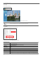
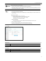
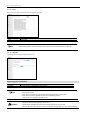
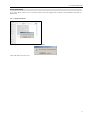
SNS-400/100 User’s Manual Thanks for purchasing the SNS-400/100. Before attempting to connect or operate this product, please read these instructions carefully and save this manual for future use. English Preface A brand that is integrated into Samsung's network products, stands for a convenient world (Polis) made safe (Police) through Samsung's superior network performance(Internet protocol). With products' clear digital images transmitted over the internet, real-time monitoring is possible anywhere with an internet connection. Easy remote control functions and the use of existing networks minimize installation costs. With , experience a world of convenience connected anytime, anywhere. Preface Thanks for purchasing the SNS-100/400 Network Server. This is a user instruction manual for high resolution D&N network server and the product mentioned here designates the high resolution D&N network server. The user who installs and operates the product should be aware of this manual and other manuals referred to by this manual before installation and operation for proper use. This manual and the software and hardware explained here are protected by copyright law. Therefore, the copy, reprint and translation to other languages in parts or full of this user manual without the express written consent of SamsungTechwin Co., LTD are not allowed aside for general use within the scope of the copyright law. 1 SNS-100/400 Network Server Contents Preface ............................................................................................................................................................1 Contents ..........................................................................................................................................................2 Note to User ....................................................................................................................................................4 FCC Compliance Statement............................................................................................................................4 Correct Disposal of This Product (Waste Electrical & Electronic Equipment) .................................................4 Product Warranty and Limitations ...................................................................................................................5 Warning Symbols ............................................................................................................................................5 Warning ...........................................................................................................................................................5 Caution ............................................................................................................................................................6 Ch1. SNS-100/400 Network Server Overview.......................................................................................................7 1.1. Introduction...............................................................................................................................................7 1.2. Features ...................................................................................................................................................7 Ch2. Product Description ......................................................................................................................................8 2.1. Components and Accessories..................................................................................................................8 2.2. Part Names ..............................................................................................................................................8 2.2.1. Front .................................................................................................................................................................. 8 2.2.2. Bottom ............................................................................................................................................................... 9 2.2.3. Back................................................................................................................................................................. 10 2.3. Recommended PC specifications .......................................................................................................... 11 Ch3. Installation and Setting ...............................................................................................................................12 3.1. Power Input ............................................................................................................................................12 3.2. Connecting to Monitor ............................................................................................................................12 3.3. Connecting to External Control Terminal................................................................................................13 3.4. Network Configuration and Connection Method.....................................................................................15 3.4.1. Configuration/connection using Web page ....................................................................................................... 15 Ch4. How to Use Web Viewer..............................................................................................................................18 4.1. How to Use Web Viewer.........................................................................................................................18 4.1.1. Login ................................................................................................................................................................ 18 4.1.2. Web Viewer Screen ......................................................................................................................................... 18 4.2. Using Administration Page .....................................................................................................................21 4.2.1. Initialization Screen after Connecting ............................................................................................................... 21 4.2.2. Live .................................................................................................................................................................. 22 4.2.3. Basic ................................................................................................................................................................ 22 4.2.4. Network............................................................................................................................................................ 23 4.2.5. User ................................................................................................................................................................. 24 4.2.6. Pan / Tilt / Zoom............................................................................................................................................... 25 4.2.7. Motion Detection .............................................................................................................................................. 26 2 Contents 4.2.8. Alarm/Sensor....................................................................................................................................................27 4.2.9. Record..............................................................................................................................................................28 4.2.10. Time ...............................................................................................................................................................29 4.2.11. LOG................................................................................................................................................................30 4.2.12. Upgrade .........................................................................................................................................................30 4.2.13. System Reboot...............................................................................................................................................31 Ch5. Troubleshooting...........................................................................................................................................32 Appendix A. DDNS Usage....................................................................................................................................34 Specifications.................................................................................................................................................36 For more information on network manager program, please see network manager quick guide and manual Note file enclosed with CD. 3 SNS-100/400 Network Server Note to User This machine’s electromagnetic waves have been registered as suitable for business purposes; the retailer and consumer should be aware of this registration. If in the case of wrongful purchases, please exchange the product for a home use product. Samsung Techwin cares for the environment at all product manufacturing stages to preserve the environment, and is taking a number of steps to provide customers with more environment-friendly products. The Eco mark represents Samsung Techwin’s will to create environment-friendly products, and indicates that the product satisfies the EU RoHS Directive. FCC Compliance Statement Caution : Any changes or modification in construction of this device which are not expressly approved the party responsible for compliance could void the user’s authority to operate the equipment. NOTE: This equipment has been tested and found to comply with the limits for a Class A digital device, pursuant to part 15 of the FCC Rules. These limits are designed to provide reasonable protection against harmful interference when the equipment is operated in a commercial environment. This equipment generates, uses, and can radiate radio frequency energy and, if not installed and used in accordance with the instruction manual, may cause harmful interference to radio communications. Operation of this equipment in a residential area is likely to cause harmful interference in which cause the user will be required to correct the interference at his own expense. Correct Disposal of This Product (Waste Electrical & Electronic Equipment) (Applicable in the European Union and other European countries with separate collection systems) This marking shown on the product or its literature, indicates that it should not be disposed with other household wastes at the end of its working life. To prevent possible harm to the environment or human health from uncontrolled waste disposal, please separate this from other types of wastes and recycle it responsibly to promote the sustainable reuse of material resources. Household users should contact either the retailer where they purchased this product, or their local government office, for details of where and how they can take this item for environmentally safe recycling. Business users should contact their supplier and check the terms and conditions of the purchase contract. This product should not be mixed with other commercial wastes for disposal. 4 Product Warranty and Limitations Product Warranty and Limitations The manufacturers of this product are not liable for anything related to sales of this product and do not consign third parites with any authorities that would make them held responsible instead of the manufacturer. The product warranty does cover accidents, negligence, abuse, or improper use for the product in whole or in any parts. Additionally, the manufacturer does not provide warranty for any additional parts or pieces that were not supplied by the manufacturer. The warranty is valid for one year from the purchase date. During the period, the warranty does not cover the malfunctions in the below areas. y Malfunction due to user’s negligence y Dismantlement or replacement by the user y Connection to alternate power source y Malfunction due to natural disasters (fire, flood, tsunami, etc.) y Replacement due to wear and tear y Instability of network Warning Symbols Before attempting to connect or operate this product, please read these instructions carefully and save this manual for future use. Danger : Misuse or wrongful operation of the product may result in death, injury or bring about other fatal results. It indicates absolute caution when operating. Caution : Misuse or wrongful operation of the product may result in slight injury or damage to the product. It indicates caution when operating. Note : Indication that the user needs to be aware of certain matters, or will find matters helpful in operating the product. Warning Before Setup y Please set up the proper voltage before connecting to power source. y Please be sure the power is turned off before setup. y There is risk of shock or fire; be sure to avoid setup in places with high humidity. y To prevent shocks, please connect the ground wire. y Unauthorized assembly forbidden. Assembly requires experience and technical skills, and unauthorized assembly has fire and shock risks. Always contact one of our agents for assembly. . y Do not install install on an unsturdy surface. There are risks of falling. 5 SNS-100/400 Network Server During Use y When opening the product cover, there is a risk of electric shock. Only a professional should open the cover. y Please use only in an environment with standard temperature and humidity. y Please do not plug in multiple products to a power source; it is often the cause of fires. y Please do not place water or heavy objects on the product; it is often a cause of malfunction. y Please do not use in a location with propane gas, gasoline or other flammable substances to avoid risk of explosion or fire. y Please do not touch the power plug with wet hands to avoid electric shock. y Do not pull on the power plug with too much force; a damaged plug may cause electric shock or fires. y Do not connect the RJ-45 cable to a terminal by constraint. y Stop use in the case of smoke or irregular heat. It may cause fires. y Random replacement of built-in lithium battery with other types of batteries may cause explosion. The battery must be replaced by the same battery. The used batteries shall be disposed carefully because they can cause environment pollution. y It is dangerous to put the battery in fire, heat or short circuit it. y Do not use batteries by recharging them. Disassembly and Cleaning y There is a risk of malfunction, shock or other dangers. Please do not disassemble or attempt to fix the product. y To prevent malfunction or shock, please do not use a wet cloth or oil-based cleaning product to clean the product exterior. Clean the exterior of the product with a dry cloth. Caution y Do not install under extreme temperature conditions Use only under temperature conditions between -0°C and +40°C. Provide good ventilation when using in high temperature conditions. y Do not drop and avoid shocks and vibration. This may cause malfunctions. y Do not install in areas exposed to rain, water or radiation. Moisture inside of the product may cause malfunctions. y Do not disassemble the product arbitrarily. After services will not be provided for arbitrarily disassembled products. y Please check the created network place first, before trying to connect to a network. y Please use only the power adapter that is provided with the product. y Please check national laws to be sure that using the product for monitoring purposes is not illegal. 6 1.1. Introduction Ch1. SNS-100/400 Network Server Overview 1.1. Introduction The SNS-100/400 is a high-tech network server that uses MPEG-4 codec technology to allow high compression rates and clear picture quality by allowing for high frame rates to be transmitted through the network. By using the network, remote connection, monitoring, and control is possible from any location for simple use; additionally, set-up requires only a network. The SNS-100/400 network server utilizes embedded software solutions (Embedded Web Server, Embedded Streaming Server, Network Protocol) developed by SamsungTechwin, and guarantees performance and safety while offering various solutions through Internet integration. 1.2. Features Monitoring Screen It sends real-time 120fps MPEG-4 data and shows single and partitioned screens (partition screen available only for SNS-400). The monitor output supports 1 composite unit. Screen Text Display Functions Using the texts displayed on the monitor screen, the camera functions can be adjusted. Motion Detection Even without an external motion sensor, this product detects motion and sends a signal. Therefore, by connecting to the alarm device, monitoring can be performed much more efficiently. Alarm and interoperation Motion Detection function is interoperated with Alarm, pictures can be transmitted via e-mail or FTP. USB Recording/Search When a USB memory device is attached to the server, events can be recorded and the recorded events can be searched directly from the webpage. High Data Compression Rate The high data compression rate based on the MPEG-4 allows high speed transmission and even from the same network bandwidth, it can send relatively more frames. Bi-directional audio and video transmission Video and bi-directional audio can be transmitted in real time and recording and playing are possible through the network manager installed on user’s PC. Additional Functions - NTSC/PAL auto detect and PTZ control is available. 7 SNS-100/400 Network Server Ch2. Product Description 2.1. Components and Accessories Server Main Frame I/O Connection POW Terminal ER N ETWO RK VID EO 12 34 SENS OR 12 3 4 SNS-4 00 Users Manual / Wall Bracket CD / Quick Guide Cross Cable DC 12V Adapter 2.2. Part Names 2.2.1. Front SNS-100 ① POWER Shows whether server power is connected. ② NETWORK When Network LED flickers, it means that the network is operating normally. ③ VIDEO Displays whether video input is detected. ④ SENSOR Shows SENSOR input. ⑤ USB USB terminal. 8 SNS-400 2.2. Part Names 2.2.2. Bottom SNS-100 SNS-400 ⑥ WALL BRACKET Connection Use this when fixing the product to the WALL BRACKET. Use the WALL BRACKET as seen in the below figure. y Remove the Foot on the bottom and connect the support to the WALL BRACKET. y SNS-100 Bottom Connection Diagram SNS-100 Dimensional Connection Diagram y With Wall Bracket attached The Wall Brackett is provided together with the server. When installing support, please see the above user’s Caution manual. 9 SNS-100/400 Network Server 2.2.3. Back SNS-100 SNS-400 ⑦ Video Input Server’s BNC video input connection terminal. ⑧Video Output Server’s BNC video output connection terminal. ⑨ Audio Input/Output IN: Audio input terminal where sound is entered to the network server. Accessories such as microphones can be connected here. OUT: Audio output terminal where sound comes out from the network server. Accessories such as speakers can be connected here. ⑩ ETHERNET Connects to 10/100 Mbps Ethernet. Use standard RJ-45 connectors to connect to Ethernet. ⑪ TERM SWITCH The switch named TERM is for selecting the RS-485/422 connection and turning the termination resistor on and off. - RS-485 select (ON: 1, 2) - RS-422 select (OFF: 1, 2) - Apply termination resistor (ON: 3, 4) ⑫ RS-485/422 Installs serial cable connected to camera that controls pan/tilt/zoom functions. ⑬ RS-232C Connection terminal to RS 232-C communication device. ⑭ ALARM Alarm Input (I): Connecting infrared sensors or other external sensor equipment. Alarm Output (O): Connecting bright light, or other relay equipment. ⑮ Power Terminal for connecting designated power. 16 Reset ○ When pressed for 5 seconds, all settings are initialized. 17 Grounding ○ Terminal for grounding product. 10 2.3. Recommended PC specifications For the sake of safe activation, we recommend to use a grounding cable and connect the grounding terminal Note and cables at the back of the product. 2.3. Recommended PC specifications Items CPU Main Memory HDD VGA OS Web Browser Resolution Network DirectX Specifications Pentium IV 3.0GHz or higher processor 1GB or higher RAM More than 120GB when recording 128M or higher recommended Window 2000, XP, 2003, Vista Internet explorer 5.5 or higher 1024*768 or higher 10/100 Base-T Ethernet 9.0C or higher 11 SNS-100/400 Network Server Ch3. Installation and Setting 3.1. Power Input DC Power Only DC12V power may be supplied to this product. When using an adapter different from the one supplied by us (DC12V/4A), make sure that it is DC12V/2A or higher. DC Only For SNS-400, the recommended adapter specs are DC12V/2A, therefore, only use standard adapters. Chart 0-1 When the copper wire’s resistance is [20℃(68℉)] Copper Wire Size (AWG) #24(0.22㎟) #22(0.33㎟) #20(0.52㎟) #18(0.83㎟) Resistance (Ω/m) 0.078 0.050 0.030 0.018 DROP Voltage(V/m) 0.028 0.018 0.011 0.06 y As seen in Chart 3-1, a voltage drop occurs and thus, in the case that the adapter output wire’s length is excessively connected to the network, a problem can occur with the network server. ※ Server Operation Voltage: DC 12V±10% ※ Depending on the type and manufacturer of the voltage load wire described in the above chart, there may be a deviation. 3.2. Connecting to Monitor Connect the video output terminal on the back of the product to the monitor input terminal. SNS-100 Network Server Monitor y Connection methods may differ depending on the used monitor and peripheral devices, so please refer to the users’ manual. y Always connect after turning the device’s power off. 12 3.3. Connecting to External Control Terminal 3.3. Connecting to External Control Terminal SNS-100 SNS-400 The input sequence of the terminal from the left is TERM, RS-485/422, RS-232C, SENSOR IN and RELAY OUT. Use a ‘-‘ driver to loosen the I/O connection terminal and remove the wire covering. After pushing in the removed portion, fixate it by tightening the screw. RS-485/422 Connection T VIDEO IN MONITOR + DC 12V - AUDIO IN ETHERMET TERM AUDIO OUT RS-485 I 422 RS-232C SENSOR IN RELAY OUT RS-485/422 according to TERM SWITCH connection TERM ON OFF 1,2 RS-485 RS-422 3,4 Termination Resistor ON Termination Resistor OFF RS-485/RS-422 Connection VIDEO IN MONITOR + DC 12V - VIDEO IN AUDIO IN ETHERMET TERM MONITOR AUDIO OUT RS-485 I 422 RS-232C SENSOR IN + DC 12V - AUDIO IN RELAY OUT ETHERMET T TERM AUDIO OUT RS-485 I 422 RS-232C SENSOR IN RELAY OUT + RS-485 RS-422 Termination Resistor Connection VIDEO IN MONITOR + DC 12V - AUDIO IN ETHERMET TERM AUDIO OUT RS-485 I 422 RS-232C SENSOR IN RELAY OUT T 13 SNS-100/400 Network Server RS-232C/SENSOR IN Connection Connect the RS-232C/SENSOR IN terminal and use as shown below. VIDEO IN MONITOR DC 12V + - AUDIO IN ETHERMET TERM AUDIO OUT RS-485 I 422 RS-232C SENSOR IN RELAY OUT VIDEO IN MONITOR + DC 12V - AUDIO IN ETHERMET 1 ○ 2 ○ 3 ○ TERM AUDIO OUT RS-485 I 422 RS-232C RS-232C SENSOR IN SENSOR IN RELAY OUT SENSOR IN S1 S2 S3 S4 GND 1 Input O - - - O 2 Input - O - - O 3 Input - - O - O 4 Input - - - O O 1, 3 Input O - O - O 1, 2, 3, 4 Input O O O O O For SNS-400 Input S1 VIDEO IN CH1 CH2 Input S2 CH3 MONITOR MONITOR CH4 1 ETHERMET ETHERMET TERM TERM 2 3 + AUDIO IN 1 DC 12V +- DC 12V - 2 4 AUDIO OUT RS-485 I 422 RS-485 I 422 RS-232C RS-232C SENSOR IN 3 RELAY OUT SENSOR IN AUDIO IN 4 AUDIO OUT RELAY OUT Input S1, S3 Input S1, S2, S3, S4 Input S3 Input S4 y In case of selecting Normal Open at setup menu: In case of contact type, it is short and in case of active type, sensor input acts at “LOW” level. y In case of selecting Normal Close at setup menu: In case of contact type, it is open and in case of active type, sensor input acts at high impedance status(open collector). RELAY OUT Connection Connect the RELAY OUT terminal and use as shown below. VIDEO IN MONITOR + AUDIO IN ETHERMET 14 TERM AUDIO OUT RS-485 I 422 RS-232C SENSOR IN RELAY OUT DC 12V - 3.4. Network Configuration and Connection Method NC CM Normal Close RELAY OUT O O - Common - O - Normal Open - O O Relay Out 1 NO Relay Out 1, 2 3.4. Network Configuration and Connection Method 3.4.1. Configuration/connection using Web page 1. Please connect user’s PC to SNS-100/400 network server using cross cable. To configure network, the internal IP must be registered in the user’s PC. Note After pressing internet protocol (TCP/IP) properties, press the ‘advanced’ button to go into advanced configurations. - Add with 192.168.1.XXX. 15 SNS-100/400 Network Server 2. Please launch Web browser on user’s PC and enter the below IP address and press the <Enter> button. Connect to Webviewer login window of SNS-100/400 network server. SNS-100 default address 3. Note 4. The initial ID and password is ID: admin, PW: 11111111 Please configure according to the network environment where SNS-100/400 network server will be installed and push <Save> button to save the configuration. ① LAN / xDSL/ DHCP Configuration 16 SNS-400 default address Please login with administrator’s authorization and move to ‘Setup-Network’ page. 3.4. Network Configuration and Connection Method Item LAN Use xDSL Video Quality Description When network product is connected to normal local LAN or when connected to static IP, the network data to be allotted to the IP is configured. When using xDSL dynamic IP, enter the ID and PW. When automatically receiving IP through DHCP server, the DHCP functions are activated. ‘DHCP’ is used in the LAN environment where the DHCP is activated. Generally, for mid/large scale, DHCP servers are operated through LAN and for small-scales, IP sharers use DHCP functions. ② Port Configuration Item Port Setting Description The connection port and http, ftp port configurations can be set here and the DDNS use can be checked. Use DDNS changes its IP address every time the user attempts to connect to the ISP and when the product is Note connected to a cable modem or xDSL modem. In this case, the user cannot know the changed IP address. When a product that uses dynamic IP is registered on the DDNS server, when wishing to connect to the product, the changed IP address can be easily recognized. In order to register the IP address to the DDNS server, set Use DDNS as Enabled. 17 SNS-100/400 Network Server Ch4. How to Use Web Viewer 4.1. How to Use Web Viewer 4.1.1. Login To connect to the login page, click the ‘move to Webpage’ button on Network Manager or enter SNS-100/400 network server IP address on the internet web browser and press the enter key. Enter user ID and password and push <Login> button, it then moves to the appropriate Web page. Note Default value is ID: admin, PW: 11111111 If you click <Guest> button, it moves to WebViewer page under the Guest authenticated status. However, administrator has to permit guest access for this. If you logged in first in administrator mode, please change the password of administrator. It can prevent Note other users from connecting to the administration page. 4.1.2. Web Viewer Screen Web Viewer screen is composed of menu area for video configuration and screen area for displaying input video. 18 4.1. How to Use Web Viewer Controls Flip Image Vertical reversal of channel screen Stretch Image When selecting resolution with Half D1 and CIF, stretches channel screen to resolution D1 size. Save Image Saves channel screen to ‘JPEG file’. Quad 4 Converts to 1 split / 4 split screens (applied only to 4 channel server) Channel Video server channels (applies only to 4 channel servers) - CH1 ~ CH4 Compression Video compression mode (the mode of compressing video) - MPEG, JPEG Resolution Video resolution (the size of video screen transmitted) - NTSC : D1(704x480), Half D1(704x240), CIF(352x240) - PAL : D1(704X576), Half D1(704X288), CIF(352X288) Frame Rate The number of maximum video frames transmitted per second. - Designated by user between 1 ~ 30 Quality Video quality setting - Very High, High, Middle, Low, Very Low Pause Stops image temporarily. OSD Displays related OSD information. Displays the title Removes the title Deinterlace On/off function of Deinterlace. 19 SNS-100/400 Network Server Screen where Deinterlace is not applied Screen where Deinterlace is applied Deinterlace is a function to adjust the video quality softly by eliminating the border line which was made by an Note interlace function. The interlace function draws an even line and an odd line of the Image one after the other. Camera Setup Pop up button for adjusting camera OSD. Camera OSD control button is displayed Camera OSD is displayed Instruction for Camera OSD control button <↑>, <↓> button Moves selection displaying arrows up and down on camera OSD menu. <←>, <→> button Changes configuration of selected field on camera OSD menu. <Set> button Used when moving to a selected field’s lower menu or when setting a selected item. <Exit> button Used when going to the upper menu of a selected field or when terminating OSD. 20 Caution Camera can be controlled only when connected to the RS-485’s configuration communication terminal. Note For camera configurations and configurations, please see the ‘Camera Manual’. 4.2. Using Administration Page PTZ Control PTZ Control Functions Screen where camera PTZ control window is displayed - The left/right slide bar can control focus (left slide bar) / zoom (right slide bar) - The “+” displayed in the middle can be pressed using the mouse as the base point of the Pan / Tilt and it will Pan /Tilt according to that point. 4.2. Using Administration Page 4.2.1. Initialization Screen after Connecting When connection is successful, the below screen will be displayed. 21 SNS-100/400 Network Server 4.2.2. Live Goes to Web Viewer Page. [Web Viewer live screen] Note In order to set detailed user menu, press the above setup menu button. 4.2.3. Basic Configures basic information for the network server. The boxes shown in red are configured only in SNS-400. Video/Audio Setup Item Compression Type Video Size Video Quality Video Frame Rate Video Channel Audio-In Channel Audio-Out Channel Max User Count MIC Sensitivity 22 Description Video compression mode (Compression mode of video in the network server) Selects the screen size. Selects the quality of video screen. In case of low speed internet, lower the video quality to see seamless video. Configures the number of transmitted frame per second in the camera. Selects the video channel to be used in the camera. Selects whether to use the audio input channel in the camera or not. Selects whether to use the audio output in the camera or not. Configures the number of users who can be connected to the camera through the network(1~20 persons) Audio amplifying function Configures Low for the microphone which has amplifying function and High for the microphone which has 4.2. Using Administration Page Item Description no amplifying function. (In case of Line-In signal, configure Low) Product Information Item Model Mac Address Camera Name Channel 1 Name Location Description Memo Description Displays model name of the network server. Displays MAC Address of the network server. Configures name of the network server and it helps to classify several network servers. Network server’s channel name can be set and when it is 4 channels, there are up Channel 1, 2, 3 and 4 names. Enters the place where the network server is installed. Enters the description for the network server and the related section. Enters the contact information for the network server administrator. 4.2.4. Network Configures the network data of the network server. Network Configuration According to the user’s network environment, it is classified as LAN, xDSL or DHCP. Item Description In case the network server is connected to the local network or xDSL with a static IP address, configure network information to be assigned to the network server. In case of xDSL with a dynamic IP address, enter password in User Name and Password field. This case is selected in case of using IP sharing box/ cable modem. LAN xDSL DHCP Port/DDNS Configuration Item Description Connection Port Port used for controlling communication with network server. (Default : 4000) HTTP Port/FTP Port Port used for connecting to network server’s webpage and FTP functions. (Default : http=80, ftp=21) Choose whether you use DDNS server. IP address for dynamic IP can continuously change, but if you use DDNS, you can connect to the server regardless of the changing IP address. Use DDNS 23 SNS-100/400 Network Server 4.2.5. User This sets password change for administrator or user registration. Item Description Administrator Password Change Change password of administrator(The initial administrator password is 11111111) Guest Setup User clicks ‘Guest’ button to decide whether allowing guest to connect to Main Viewer from the login page. You can register new user or delete, and set up user’s authority(applied only to 4 channel servers) Current Users ※ Setup User Authority User’s authorities set up at ‘Current User’ are as follows. Item Description Video Use video related setup function (Compression, Resolution, Framerate, Quality) Controls Audio – In Use Pan, Tilt, Zoom, Audio output, Alarm output Audio Input Whether relevant account is used(If not checked, log-in not permitted) Example 1) In case control function is limited (Do not check Controls box) ※ Pan, tilt, zoom, audio output, alarm output function icon is inactivated Example 2) In case video function is restricted (When Video is not checked) 24 4.2. Using Administration Page ※ Compression, Resolution, Framerate, Quality set up icon is inactivated. 4.2.6. Pan / Tilt / Zoom Configures items for the network server’s PTZ functions. Pan / Tilt / Zoom Setup ◊ PTZ Camera Configuration Item Description Channel Select channel where camera is installed (applied only to 4 channel servers) PTZ Display OSD Display Preset Swing Group Device ID Set whether to display PTZ control tool on screen Set whether to display OSD menu in camera Register/use selected preset or delete registered preset Set whether to activate in set swing mode Set whether to activate registered group mode Select ID allotted to camera and differentiate camera to be controlled Mode Select the connected camera’s protocol per manufacturer and model Note - Pan/Tilt Swing group motions are supported only by our protocol. - Up to eight different presets for the zoom camera are supported. 25 SNS-100/400 Network Server ◊ RS485/422 Setup Item Description Baud Rate Data Bit Parity Bit Stop Bit Set the data transmission speed per second Set the data transmission bit Select error-check method when data is displayed Set insert bit when data transmission is completed Caution When RS-485/422 setup configuration is incorrect, the PTZ camera motion may not work. See the users’ manual for the connected camera and carefully configure it accordingly. ◊ Swing Setup Item Description First Preset / Second Preset Mode Speed Duration Designate the two presets to be used in swing mode Select movement method between the two points((Pan/Tilt Swing) Set movement speed Sets the stop time at one preset point ◊ Group Setup Item Description Group No. Preset No. Travel Speed Dwell Time Sets the desired group number Sets each point’s preset number Sets the travel speed between each point interval Sets the stop time at each position 4.2.7. Motion Detection This sets up motion detection function of the network server. ◊ Motion Detection Configuration Item Channel Set Grid Display Select Area MD Enable MD Sensitivity 26 Description Used when selecting the channel. (Applied only to 4 channel servers.) Basic grid, used to choose area on the screen, is displayed or hidden. When selecting motion detection area, click <Select All> button to select all areas, or click <Deselect> button to cancel the selected area. Decide whether you use motion detection function. Setting up sensitivity to detect motion to adjust input video by situation. You can select 1-5, and 5 is the highest. 4.2. Using Administration Page - After setting is complete, click the Set button to apply the settings. Note 4.2.8. Alarm/Sensor This sets up necessary information when using alarm function by attaching sensor to network server. For SNS-100 For SNS-400 Alarm/Sensor Setup ◊ Digital In (Sensor) Setup Item Description Sensor Type Types of sensors are ‘Normal open’ and ‘Normal close.’ This selects up type of connected sensor. ◊ Digital Out (Relay / Alarm) Setup Item Description Relay Set up Relay Out responding when event is recognized by connected sensor or Motion Detection (MD) Set up time to operate relay. It defines the period from the time when sensor detects event to the time when relay is released. In case event occurs by sensor or Motion Detection (MD) on the screen, decide whether transferring related information to FTP. Duration FTP In case event occurs by connected sensor or Motion Detection (MD) on the screen, decide whether transferring related information by e-mail. E-mail FTP / E-mail Setup Set up FTP server and e-mail information to which related information is transferred in case alarm occurs. ◊ FTP Setup Item FTP FTP Server Name Home Directory User ID User Password Description Enters the FTP server or Domain IP address. Set up home directory to save relevant data at FTP server. Enter ID to connect FTP server. Enter PW to connect FTP server. 27 SNS-100/400 Network Server ◊ E-mail Setup Item Description Recipient E-mail Address 1 Recipient E-mail Address 2 SMTP Server Name ID Password Mail Subject Mail Body You can designate up to two e-mail address receiving data when alarm occurs. In case you use outside e-mail server, enter the name of the outside e-mail server. Enter ID to connect the outside e-mail server. Enter PW to connect the outside e-mail server. Enter the subject of mail to be transferred. Enter the body of mail to be transferred. If motion is detected, the contents transferred by e-mail or to FTP are varied according to the set-up of ‘Video Compression’ at Admin page (Basic). Note MPEG : Video length is set by ‘Duration’ of ‘Digital Out (Relay/Alarm) Setup’. File extension is ‘ste’, you can play this by ‘SLiM Player’. JPEG : JPG type image file attached. 4.2.9. Record Record Page Item Description USB Memory Size Displays the entire capacity of the USB memory. USB Memory Recordable Size Displays the capacity possible for recording for the USB memory. USB Memory Free Size Displays the remaining capacity of the USB memory. Button for playing the video Button for stopping the video Button for pausing the video Save video as JPG file Event Recording Video List 28 Event video list saved in the USB memory saves 5 seconds of pre-record and 5 post records. 4.2. Using Administration Page Caution USB memory must be attached before operating the system. USB 2.0 memory sticks are recommended. Number of users possible for simultaneously using Record is limited to 1. During initial operation of the product, USB memory initialization begins and during initializing, the record function cannot be used.(1Gb: 2~3 minutes) USB save function method. Note The file system supports FAT and FAT32 It is saved in the SNS_DATA folder and depending on the usable capacity; the number and sizes of the files can change USB save function specs. Interoperation with events (MD, V-Loss, Sensor) - Saves pre and post 5 seconds of the corresponding channel - MPEG (saves as set frame), JPEG (1 page / 1 second) - When audio is on, the audio is also saved REPEAT RECORDING - When all storage space is used, it deletes old save data and begins a new save cycle. Up to 1,000 events can be saved. It saves it in the same resolution as that of the LIVE screen (D1, HD1, CIF) SanDisk and TRANSCEND products are recommended for the USB memory. 4.2.10. Time Current Time Item Date Time Description Current setup date displayed on network server. Current setup time displayed on network server. Time Setup Item Set Manually Time Server Description Adjust network server time manually. Set up address of time server for Server 1 - 5. 29 SNS-100/400 Network Server 4.2.11. LOG Recent activities made for network server are displayed in a log. Item Clear Description Delete logs. Note When checking Send Log to Administrator E-mail, logs are sent to the administrator e-mail at 04:00 4.2.12. Upgrade Upgrade program of SNS-100/400 network server. System Upgrade Configuration. Item Firmware Description Upgrade firmware of SNS-100/400 network server. Upgrade methods are as shown below. Note - Check current version. Press ‘search‘ and select the latest version firmware file and press the ‘send’ button. When ‘send’ is pressed, upgrades are done and it automatically reboots. Lastly, check if it is changed to the latest version. -Upgrades should be performed only by technicians. Caution - Always perform upgrades after connecting the product and PC with a cross cable. - When the network is disconnected or power is turned off during upgrades, the product may be damaged. 30 4.2. Using Administration Page Factory Mode Setup If you click <Reset> button, server is returned to initial value when shipped from the factory after confirmation procedure by administrator. 4.2.13. System Reboot Server is rebooted after confirmation procedure of administrator. Click <OK> button to reboot server. 31 SNS-100/400 Network Server Ch5. Troubleshooting Before Calling for Malfunctions If there are problems in operation, please refer to the items below. If the problem persists, please contact the agent you purchased this product from Problem Nothing appears on the screen. Solution Please check the power connection. Please check the video signal line connection. Check if there is anything wrong with the video signals entered to the network server. Open MS-DOS window to check whether SNS-100/400 network server is connected to the network. In case of ping 192.168.0.100, replace it with IP address set up at server ※ In case of ping 192.168.0.100, replace it with IP address set up at server. The video image is not clear. Please check if the lens is clean. Please clean the lens with a clean cloth or brush. Please adjust the contrast feature of the monitor. Please make sure that the screen is not exposed directly to bright light. Please move the angle or location of the image if necessary. Please readjust the back focus of the connected camera. The screen is dark. Please adjust the contrast feature of the monitor. Check if the terminals are properly set between the systems. Please check if an auto iris lens is being used and adjust the brightness level. There is a problem with operations. The surface is too hot and black stripes appear on the screen. Does the power supplied to the server sway away from standards or change depending on the time? The MOTION DETECTION function is not working. Please check if 'MOTION DETECTION' mode is turned on. Please check if the MD LEVEL is too low. Please check the setting of the MD AREA. The screen flickers too much. Check if the connected camera faces directly into the sun or lights. Audio is not working Please check the audio is selected from admin page. Check if the cables are properly connected. Please check speaker volume from the viewer. In case input sound through microphone at Viewer is not outputted through Audio Out of server, please check whether Audio Out channel is selected at admin page. Or check whether microphone is available at Viewer. Please check audio driver is working in user’s PC. Video is stopped Please check whether network cable of SNS-100/400 network server is correctly connected. In case user uses hub or IP router, check whether these network equipments are working properly. Open MS-DOS window and check whether SNS-100/400 network server is connected to the network. No image from web viewer Click ‘refresh (shortcut; F5) ’ button at browser to recall the page Check whether power of server and network cable is properly connected. Check whether computer is connected to network. If you use a hub or router, check whether such equipments are properly operated. (Note: Open MS-DOS window and enter network server IP at ping 192.168.1.100.(120)) Connect to Admin page to check whether video output is selected. No network connection from Network Manger, dedicated viewer Network Manger 32 Please check MAC address and IP address of SNS-100/400 network server. Check whether network cable is properly connected. (Note : Use ping command) Check whether connecting to Admin page is available. 4.2. Using Administration Page Problem Solution Image transferred to FTP or by E-mail cannot be viewed Video may not be viewed since Divx codec is not installed in user’s PC. Divx codec can decode video compressed with MPEG4. Download and install the latest Divx codec, and check video. http://www.divx.com/divx/download When camera cannot be controlled for Pan/ Tilt/ Zoom Check the camera / speed dome protocol. When the contents stored on the USB memory does not appear Make sure not to remove it when it is being saved on the USB When product data is not displayed in the local network Check the network cable’s connection status. See if the proper model and manufacturer is selected at the mode. Inspect the cables connected to the device. Check if the USB is properly connected. Make sure that capacity display is accurate on the Record Page. Press the reset switch on the back of the product for 5 seconds and factory initialize the product to check. 33 SNS-100/400 Network Server Appendix A. DDNS Usage Step2) Register the equipment after login. Registration process of DDNS is as following: Step1) Complete the registration form in iPOLiS website. The website is ‘www.samsungipolis.com’. Figure A-4. Login Figure A-5 The list of registered equipment. Figure A-1. Website of iPOLiS Figure A-6. The list of registered equipment. Figure A-2. Membership Registration: SIGNUP Figure A-7. Product Registration.(Confirm repetition certainly at domain registration.) Figure A-3. Membership Registration: Input your information. 34 Appendix A. DDNS Usage Step3) Configure DDNS information in the equipment. y Click the part of Network Configuration in website of Network Server. Step4) Confirm the connection status of relevant product in product list of iPOLiS website. y Click “USE DDNS” in order to do “Enable” and input the address of DDNS Server. (Default: www.samsungipolis.com ) y Enter the ID and Password that is written when register product is in iPOLiS website.. Figure A-8. The List of Product. Be able to confirm the information of connected equipment if click <check> button of ‘Product information’. The Configuration of DDNS in SNP-100/400 is Completed. Figure A-9. Product information Move to Login website of relevant product if click <view> button of ‘ view’. The buttons which are <Edit> and <Delete> of ‘product management’ move to relevant page through input password to item that fertilize or erase information of registered equipment in List of product. Only, ‘ID(Domain)’ of product should establishes again as ‘ID(Domain)’ after deleting because it can’t be fertilized. Figure A-10. Edit/Delete 35 SNS-100/400 Network Server Specifications Specifications SNS-400 SNS-100 Video Input BNC(X4) BNC(X1) Video Output BNC(X1), Quad Display BNC(X1), Loop Out Output Video Format MPEG4 / MJPEG Selectable Output Resolution Frame Rate NTSC : 704 x 480(D1), 704 x 240(Half D1), 352 x 240(CIF) PAL : 704 x 576(D1), 704 x 288(Half D1), 352 x 288(CIF) Max 120 fps (CIF) Max 30 fps (D1, CIF) Max 30 fps (D1) Video Compression Stage 5 stages (Very Low, Low, Middle, High, Very High) Audio Format Bi-directional audio, 8KHz ADPCM Ethernet 10/100Mbps Protocol HTTP, TCP/IP, PPPOE, FTP, SMTP, DHCP, DNS, DDNS, NTP Dynamic IP Supports XDSL and DHCP DDNS Supports DDNS Max, User S/W I/O Specs 20 Users PC Viewer Network Manager (DVR/Server/IPCam Integrated Manager S/W) Web Page Web ActiveX Control SDK Embedded Web Server Audio Input Mini Jack(X4), Mono, Line or Mic level Audio Output Mini Jack(X1), Mono Ethernet RJ-45 Connector(X1) : 10/100 Base Ethernet Sensor Input Terminal(X4) Terminal(X2) Relay Output Terminal(X4) Terminal(X2) Serial Interface RS-422/485 Terminal(X1), RS-232C Terminal(X1) USB Port USB 2.0 (Front, For Flash Memory Storage) Supports 3rd party SDK Power source DC12V±10%(AC Adapter included) Power consumption App. 12W Operating Environment -10℃ to +50℃ / 30% to 80% RH Dimensions 190mm(W) × 45mm(H) × 135mm(D) Weight (main frame) App. 845g 36 App. 8W App. 765g CD(X1) - - I/O connector (X2) - Wall Bracket(X2) - AC adapter(X1) - - AC power cord(X1) - Accessories Mini Jack(X1), Mono, Line or Mic level User Manual(X1) Ethernet Cross Cable(X1) SAMSUNG TECHWIN CO.,LTD. SAMSUNG OPTO-ELECTRONICS UK, LTD. 145-3, Sangdaewon-dong, Jungwon-gu, Seongnam-si, Gyeonggi-do, 462-120, Korea Tel: +82-31-740-8151~8 Fax: +82-31-740-8145 Samsung House, 1000 Hillswood Drive, Hillswood Business Park Chertsey, Surrey KT16 OPS Tel: +44-1932-45-5308 Fax: +44-1932-45-5325 www.samsungcctv.com www.samsungipolis.com P/No.: Z6806.0825.01C