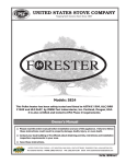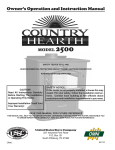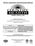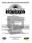
1
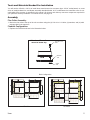
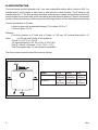
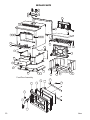
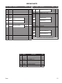
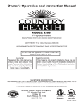
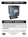
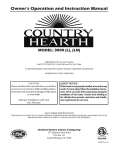
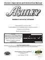
Owner’s Operation and Instruction Manual
MODELS: AFS4150, AFS6500
SAFETY TESTED TO UL 1482 and ULC-S627
US ENVIRONMENTAL PROTECTION AGENCY PHASE II CERTIFIED WOODSTOVE
WASHINGTON STATE APPROVED
MOBILE HOME APPROVED (U.S. ONLY)
CAUTION!
Please read this entire manual before you
install or use your new room heater. Failure
to follow instructions may result in property
damage, bodily injury, or even death.
Improper Installation Could Void
Your Warranty!
SAFETY NOTICE:
If this heater is not properly installed, a house
fire may result. For your safety, follow the installation instructions. Never use make-shift
compromises during the installation of this
heater. Contact local building or fire officials
about permits, restrictions and installation
requirements in your area.
SAVE THESE INSTRUCTIONS
STATES ST
OV
TED
NI
USSC
COMPANY
E
U
THIS MANUAL WILL HELP YOU TO OBTAIN EFFICIENT, DEPENDABLE SERVICE FROM THE HEATER, AND ENABLE YOU
TO ORDER REPAIR PARTS CORRECTLY. KEEP IN A SAFE PLACE FOR FUTURE REFERENCE.
United States Stove Company
227 Industrial Park Road
P.O. Box 151
South Pittsburg, TN 37380
TESTED &
LISTED BY
AFS4150 Report #: 215-S-29b-4
AFS6500 Report #: 215-S-23b-4
851823 rev A
CONGRATULATIONS!
You’ve purchased a heater from North America’s oldest manufacturer of wood burning products.
By heating with wood you’re helping to CONSERVE ENERGY!
Wood is our only Renewable Energy Resource. Please do your part to preserve our wood supply. Plant at least one
tree each year. Future generations will thank you.
The instructions pertaining to the installation of your wood stove comply with UL-1482 and ULC-S627 standards.
Combustible :
Model
Wood
Colors :
Metallic Black
Flue Pipe Diameter :
6” (152.5mm)
Flue Pipe Type: (Standard Single Wall or Double Wall):
Black or Blued Steel 2100°F (650°C)
Minimum Chimney Hieght :
12’ (3.7m)
Maximum Log Length :
21” (533.5mm)
Dimensions
Overall :
Depth x Width x Height :
AFS4150
20 1/2” x 27” x 31 3/4” (521mm x 686mm x 806mm)
AFS6500
25” x 27” x 31 3/4” (635mm x 686mm x 806mm)
Combustion Chamber :
Width x Depth :
AFS4150
22 3/4” x 12” (578mm x 305mm)
AFS6500
22 3/4” x 16 1/2” (578mm x 419mm)
Volume :
AFS4150
1.86 ft³ (.0527m³)
Cubic Feet:
AFS6500
2.69 ft³ (.0761m³)
Door Opening : Width x Height:
Pyroceramic Glass Door : (Viewing) Width x Height:
16” x 8” (406.5mm x 203mm)
13
13 /16” x 8 3/8” (351mm x 213mm)
Weight (lbs):
AFS4150
295 lbs (134kg)
AFS6500
345 lbs (157kg)
OPTIONAL ACCESSORIES
DESCRIPTION
PART #
Outside Air Intake Kit
50FAK
CAUTIONS:
• HOT WHILE IN OPERATION. KEEP CHILDREN, CLOTHING AND FURNITURE AWAY.
CONTACT MAY CAUSE SKIN BURNS.
• DO NOT USE CHEMICALS OR FLUIDS TO IGNITE THE FIRE.
• DO NOT LEAVE THE STOVE UNATTENDED WHEN THE DOOR IS SLIGHTLY OPENED.
• DO NOT BURN GARBAGE, FLAMMABLE FLUID SUCH AS GASOLINE, NAPHTHA
OR MOTOR OIL.
• DO NOT CONNECT TO ANY AIR DISTRIBUTION DUCT OR SYSTEM.
• ALWAYS CLOSE THE DOOR AFTER THE IGNITION.
2
Ussc
CUT HERE
"
WARRANTY INFORMATION CARD
Name__________________________________________ Telephone #: (_____)_____________
City____________________________________________ State_______ Zip_________________
Email Address __________________________________________________________________
Model # of Unit________________________________ Serial #___________________________
Fuel Type: qWood qCoal qPellet qGas
qOther _________________________
Place of Purchase (Retailer)______________________________________________________
City____________________________________________ State_______ Zip_________________
If internet purchase, please list website address___________________________________
Date of Purchase _______________________________________________________________
Reason for Purchase:
qAlternative Heat
qDecoration
qCost
qMain Heat Source
qOther _________________________
What was the determining factor for purchasing your new appliance?_______
I have read the owner’s manual that accompanies this unit and fully understand the:
Installation qOperation q and Maintenance q of my new appliance.
Print Name
Signature
Date
Please attach a copy of your purchase receipt.
Warranty not valid without a Proof of Purchase.
"
CUT HERE
Warranty information must be received within 30 days of original purchase.
Detach this page from this manual, fold in half with this page to the inside and tape
together. Apply a stamp and mail to the address provided. You may use an envelope if you choose.
You may register online by going to www.usstove.com
Ussc
All information submitted will be kept strictly confidential. Information provided will not be sold for advertising purposes.
Contact information will be used solely for the purpose of product notifications.
3
CUT HERE
"
Ê
Fold Here
Fold Here
É
Place
Stamp
Here
"
4
CUT HERE
United States Stove Company
P.O. Box 151
South Pittsburg, TN 37380
Ussc
Tools and Materials Needed For Installation
You will need a drill with a 1/8” bit to install sheet metal screws into connector pipe. A 5/16” socket/wrench or screw
driver to install pedestal trim, and blower assembly described below. A 1/2” socket/wrench to install flue collar. A noncombustible floor protector as specified in this manual. All chimney and chimney connector components required for
your particular chimney installation. For mobile homes, see page 13.
Assembly
Flue Collar Assembly:
1. Mount the flue collar to the top of the unit as shown using the (3) 5/16-18 x 1-1/2 bolts, (3) washers, and (3) weld tabs provided in the parts box.
Firebrick Configuration:
1. Replace the Firebrick as shown in the illustration below.
Side view of flue collar
mount to heater top
5/16-18 x 1-1/2
BOLT
HEATER
TOP
WELD
TAB
Brick Configuration
AFS4150
Ussc
AFS6500
5
BLOWER ASSEMBLY INSTRUCTIONS
THE BLOWER ASSEMBLY MUST BE DISCONNECTED FROM THE SOURCE OF ELECTRICAL
SUPPLY BEFORE ATTEMPTING THE INSTALLATION.
Step 1.
Fix the assembly to the back of the stove with the four screws provided.
THE BLOWER ASSEMBLY IS INTENDED FOR USE ONLY WITH A STOVE THAT IS MARKED
TO INDICATE SUCH USE.
DO NOT ROUTE THE SUPPLY CORD NEAR OR ACROSS HOT SURFACES!
PEDESTAL TRIM ASSEMBLY
Assemble trim pieces as shown with the screws
provided in the parts bag. Washers may not be
necessary.
After trim assembly, attach to the pedestal base at the
location shown using the screws provided.
6
Ussc
INSTALLATION
SAFETY NOTICE
• IF THIS STOVE IS NOT PROPERLY INSTALLED, A HOUSE FIRE MAY RESULT. TO
REDUCE THE RISK OF FIRE, FOLLOW THE INSTALLATION INSTRUCTIONS.
• CONSULT YOUR MUNICIPAL BUILDING DEPARTMENT OR FIRE OFFICIALS ABOUT
PERMITS, RESTRICTIONS AND INSTALLATIONS REQUIREMENTS IN YOUR AREA.
• USE SMOKE DETECTORS IN THE ROOM WHERE YOUR STOVE IS INSTALLED.
• KEEP FURNITURE AND DRAPES WELL AWAY FROM THE STOVE.
• NEVER USE GASOLINE, GASOLINE-TYPE LANTERN FUEL, KEROSENE, CHARCOAL
LIGHTER FLUID, OR SIMILAR LIQUIDS TO START OR “FRESHEN UP” A FIRE IN THIS
HEATER. KEEP ALL SUCH LIQUIDS WELL AWAY FROM THE HEATER WHILE IT IS IN
USE.
• IN THE EVENT OF A CHIMNEY FIRE, PUSH THE AIR CONTROL FULL CLOSED TO
DEPRIVE THE FIRE OF OXYGEN. CALL THE FIRE DEPARTMENT.
• DO NOT CONNECT TO ANY AIR DISTRIBUTION DUCT OR SYSTEM.
• A SOURCE OF FRESH AIR INTO THE ROOM OR SPACE HEATED SHALL BE PROVIDED
WHEN REQUIRED.
POSITIONING THE STOVE
It is very important to position the wood stove as close as possible to the chimney, and in an area
that will favor the most efficient heat distribution possible throughout the house. The stove must
therefore be installed in the room where the most time is spent, and in the most spacious room
possible. Recall that wood stoves produce radiating heat, the heat we feel when we are close to a
wood stove. A wood stove also functions by convection, that is through the displacement of hot air
accelerated upwards and its replacement with cooler air. If necessary, the hot air distribution from
the stove may be facilitated by the installation of a blower.
The wood stove must not be hooked up to a hot air distribution system since an excessive
accumulation of heat may occur.
A wood stove must never be installed in a hallway or near a staircase, since it may block the
way in case of fire or fail to respect required clearances.
Ussc
7
FLOOR PROTECTOR
Your wood stove should be placed on a 1 inch, non-combustible surface with a k factor of 0.84. For
multiple layers, add R-values of each layer to determine the overall R-value. The R value for the
required board is 1.2. The floor protector should be under the stove, twenty-six inches beyond the front
and six inches beyond each side of the fuel loading and ash removal opening. If there is a horizontal
section of chimney connector, the floor protector should go under it and two inches beyond each side
Convert specification to R-value:
k-factor is given with a required thickness (T) in inches: R=1/k x T
C-factor is given: R=1/C
Example:
If the floor protector is 4” brick with a C-factor of 1.25 over 1/8” mineral board with a “k”
factor of 0.29 the total R-value of the system is:
4” brick C=1.25, R=1/1.25=0.8
1/8” mineral board K=0.29, R=1/0.29 x 0.125=0.431
Total R = Rbrick + Rmineral = 0.8 + 0.431 = 1.231
Total R is greater than 1.2, the system is acceptable.
The floor protector should exceed the stove as follows:
Model
AFS4150
AFS6500
8
Front
25”
(635mm)
26”
(660mm)
Sides
8”
(203mm)
8”
(203mm)
Rear
6”
(152mm)
6”
(152mm)
Ussc
CLEARANCES TO COMBUSTIBLES
It is of utmost importance that the clearances to combustible materials be strictly adhered to during
installation of the stove. Refer to the tables below :
Single Wall Pipe (Double Wall Pipe)
B
C
D
E
22(20)
22.5(16.5)
32(30)
12(11)
Model
A
AFS4150
(508mm(356mm)) (559mm(508mm)) (572mm(419mm)) (813mm(762mm)) (305mm(279mm)) (559mm(533mm))
AFS6500
20(14)
12
(305mm)
20
(508mm)
16
(406mm)
30
(762mm)
10.5
(267mm)
F
22(21)
20
(508mm)
• Floor to ceiling height must be at least 7’ (2.13m) in all cases.
• Do not place any combustible material within 4’ (1.2m) of the front of the unit.
• The clearance between the flue pipe and a wall are valid only for vertical walls and for vertical flue
pipe.
• The chimney connector must not pass through an attic or roof space, closet or similar concealed
space, a floor, or a ceiling.
• In Canadian installation where passage through a wall, or partition of combustible construction is
desired, the installation must conform to CAN/CSA-B365.
• A flue pipe crossing a combustible wall must have a minimum clearance of 18” (457.2mm).
• To reduce flue clearances from combustible materials, contact your local safety department.
Ussc
9
CHIMNEY CONNECTOR (STOVE PIPE)
Your chimney connector and chimney must have the same diameter as the stove outlet (6”). If this
is not the case, we recommend you contact your dealer in order to insure there will be no problem
with the draft.
The stove pipe must be made of aluminized or cold roll steel with a minimum thickness of 0.021” or
0.53 mm. It is strictly forbidden to use galvanized steel.
Your smoke pipe should be assembled in such a way that the male section (crimped end) of the pipe
faces down. Attach each of the sections to one another with three equidistant metal screws.
The pipe must be short and straight. All sections installed horizontally must slope at least 1/4 inch
per foot, with the upper end of the section toward the chimney. Any installation with a horizontal
run of chimney pipe must conform to NFPA 211. You may contact NFPA (National Fire Protection
Association) and request the latest edition of the NFPA Standard 211.
To insure a good draft, the total length of the coupling pipe should never exceed 8’ to 10’ (2.4m
to 3.04 m). (Except for cases of vertical installation, cathedral-roof style where the smoke exhaust
system can be much longer and connected without problem to the chimney at the ceiling of the room).
There should never be more than two 90 degrees elbows in the smoke exhaust system.
Installation of a “barometric draft stabilizer” (fireplace register) on a smoke exhaust system is
prohibited.
Furthermore, installation of a draft damper is not recommended. Indeed, with a controlled combustion
wood stove, the draft is regulated upon intake of the combustion air in the stove and not at the exhaust.
10
Ussc
CHIMNEY
Your wood stove may be hooked up with a 6” factory built or masonry chimney. If you are using a
factory built chimney, it must comply with UL 103 standard; therefore it must be a Type HT (2100°F).
It is extremely important that it be installed according to the manufacturer’s specifications.
If you are using a masonry chimney, it is important that it be built in compliance with the specifications of the National Building Code. It must be lined with fire clay bricks, metal or clay tiles sealed
together with fire cement. (Round flues are the most efficient).
The interior diameter of the chimney flue must be identical to the stove smoke exhaust. A flue which
is too small may cause draft problems, while a large flue favours rapid cooling of the gas, and hence
the build-up of creosote and the risk of chimney fires. Note that it is the chimney and not the stove
which creates the draft effect; your stove’s performance is directly dependent on an adequate draft
from your chimney.
The following recommendations may be useful for the installation of your chimney:
1. Do not connect this unit to a chimney flue serving another appliance.
2. It must rise above the roof at least 3’ (0.9m) from the uppermost point of contact.
3. The chimney must exceed any part of the building or other obstruction within a 10’ (3.04m)
distance by a height of 2’ (0.6m).
4. Installation of an interior chimney is always preferable to an exterior chimney. Indeed, the
interior chimney will, by definition, be hotter than an exterior chimney, being heated up
by the ambient air in the house. Therefore the gas which circulates will cool more slowly,
thus reducing the build-up of creosote and the risk of chimney fires.
5. The draft caused by the tendency for hot air to rise will be increased with an interior chimney.
6. Using a fire screen at the extremity of the chimney requires regular inspection in order
to insure that it is not obstructed thus blocking the draft, and it should be cleaned when
used regularly.
Ussc
11
FACTORY BUILT CHIMNEY :
When a metal prefabricated chimney is used, the manufacturer’s installation instructions must be
followed. You must also purchase (from the same manufacturer) and install the ceiling support
package or wall pass-through and “T” section package, firestops (where needed), insulation shield,
roof flashing, chimney cap, etc. Maintain proper clearance to the structure as recommended by the
manufacturer. The chimney must be the required height above the roof or other obstructions for
safety and proper draft operation.
12
Ussc
MASONRY CHIMNEY :
Ensure that a masonry chimney meets the minimum standards of the National Fire Protection Association (NFPA) by having it inspected by a professional. Make sure there are no cracks, loose
mortar or other signs of deterioration and blockage. Have the chimney cleaned before the stove is
installed and operated. When connecting the stove through a combustible wall to a masonry chimney, special methods are needed.
Ussc
13
Combustible Wall Chimney Connector Pass-Throughs
Method A. 12” (304.8 mm) Clearance to Combustible Wall Member: Using a minimum thickness 3.5” (89 mm) brick and a 5/8”
(15.9 mm) minimum wall thickness clay liner, construct a wall passthrough. The clay liner must conform to ASTM C315 (Standard
Specification for Clay Fire Linings) or its equivalent. Keep a minimum of 12” (304.8 mm) of brick masonry between the clay liner and
wall combustibles. The clay liner shall run from the brick masonry
outer surface to the inner surface of the chimney flue liner but not
past the inner surface. Firmly grout or cement the clay liner in place
to the chimney flue liner.
Method B. 9” (228.6 mm) Clearance to Combustible Wall Member:
Using a 6” (152.4 mm) inside diameter, listed, factory-built SolidPak chimney section with insulation of 1” (25.4 mm) or more, build
a wall pass-through with a minimum 9” (228.6 mm) air space between the outer wall of the chimney length and wall combustibles.
Use sheet metal supports fastened securely to wall surfaces on all
sides, to maintain the 9” (228.6 mm) air space. When fastening
supports to chimney length, do not penetrate the chimney liner (the
inside wall of the Solid-Pak chimney). The inner end of the SolidPak chimney section shall be flush with the inside of the masonry
chimney flue, and sealed with a non-water soluble refractory cement. Use this cement to also seal to the brick masonry penetration.
Method C. 6” (152.4 mm) Clearance to Combustible Wall Member:
Starting with a minimum 24 gage (.024” [.61 mm]) 6” (152.4 mm)
metal chimney connector, and a minimum 24 gage ventilated wall
thimble which has two air channels of 1” (25.4 mm) each, construct
a wall pass-through. There shall be a minimum 6” (152.4) mm separation area containing fiberglass insulation, from the outer surface
of the wall thimble to wall combustibles. Support the wall thimble,
and cover its opening with a 24-gage minimum sheet metal support. Maintain the 6” (152.4 mm) space. There should also be a
support sized to fit and hold the metal chimney connector. See that
the supports are fastened securely to wall surfaces on all sides.
Make sure fasteners used to secure the metal chimney connector
do not penetrate chimney flue liner.
Method D. 2” (50.8 mm) Clearance to Combustible Wall Member: Start with a solid-pak listed factory built chimney section at
least 12” (304 mm) long, with insulation of 1” (25.4 mm) or more,
and an inside diameter of 8” (2 inches [51 mm] larger than the 6”
[152.4 mm] chimney connector). Use this as a pass-through for
a minimum 24-gauge single wall steel chimney connector. Keep
solid-pak section concentric with and spaced 1” (25.4 mm) off the
chimney connector by way of sheet metal support plates at both
ends of chimney section. Cover opening with and support chimney
section on both sides with 24 gage minimum sheet metal supports.
See that the supports are fastened securely to wall surfaces on all
sides. Make sure fasteners used to secure chimney flue line.
NOTES:
1. Connectors to a masonry chimney, excepting method B, shall extend in one continuous section
through the wall pass-through system and the chimney wall, to but not past the inner flue liner face.
2. A chimney connector shall not pass through an attic or roof space, closet or similar concealed
space, or a floor, or ceiling.
14
Ussc
OUTSIDE COMBUSTION AIR
Your wood stove is approved to be installed with an outside air intake which is necessary for a mobile
home. This type of installation is also required in air tight houses and houses with negative pressure
problems. You can purchase this option through your heater dealer. Make sure to specify the part
number mentioned in this booklet. Installation instructions are supplied with the air intake kit.
Outside combustion air may be required if :
1.Your stove does not draw steadily, smoke rollout occurs, wood burns poorly, or back-drafts occur
whether or not there is combustion present.
2.Existing fuel-fired equipment in the house, such as fireplaces or other heating appliances, smell,
do not operate properly, suffer smoke roll-out when opened, or back-drafts occur whether or not
there is combustion present.
3.Opening a window slightly on a calm (windless) day alleviates any of the above symptoms.
4.The house is equipped with a well-sealed vapor barrier and tight fitting windows and/or has any
powered devices that exhaust house air.
5.There is excessive condensation on windows in the winter.
6.A ventilation system is installed in the house.
For use in MOBILE HOMES (U. S. installations ONLY):
• WARNING! DO NOT INSTALL IN SLEEPING ROOM.
• CAUTION! THE STRUCTURAL INTEGRITY OF THE MOBILE HOME FLOOR, WALL, AND
CEILING/ROOF MUST BE MAINTAINED.
• INSTALL IN ACCORDANCE WITH 24 CFR, PART 3280 (HUD).
• USE A FACTORY BUILT CHIMNEY THAT COMPLIES WITH UL 103 STANDARDS;
THEREFORE IT MUST BE A TYPE HT (2100°F).
• USE A SPARK ARRESTER.
• THE STOVE MUST BE ATTACHED TO THE STRUCTURE OF THE MOBILE HOME. USE
THE FOUR(4) HOLES IN THE BOTTOM FLANGES OF THE HEATER’S PEDESTAL TO
SECURE THE UNIT TO THE FLOOR. THEN INTALL/RE-INSTALL THE TRIM.
Ussc
15
WOODSTOVE UTILIZATION
Your heating unit was designed to burn wood only; no other materials should be burned. Waste and other flammable
materials should not be burned in your stove. Any type of wood may be used in your stove, but specific varieties have
better energy yields than others. Please consult the following table in order to make the best possible choice.
TYPE
WEIGHT
PER CORD
EFFICIENCY
RANKING
SPLITS
MILLIONS
BTU’s/CORD
Hickory
63
4500
1.0
Well
31.5
White Oak
48
4100
.9
Fair
28.6
Red Oak
46
3900
.8
Fair
27.4
Beech
45
3800
.7
Hard
26.8
Sugar Maple
44
3700
.6
Fair
26.2
Black Oak
43
3700
.6
Fair
25.6
Ash
42
3600
.5
Well
25.0
Yellow Birch
40
3400
.4
Hard
23.8
Red Maple
38
3200
.3
Fair
22.6
Paper Birch
37
3100
.3
Easy
22.1
Elm/Sycamore
34
2900
.2
Very Difficult
20.1
Red Spruce
29
1800
.1
Easy
16.1
(LBS. CU. FT.,
DRY)
It is EXTREMELY IMPORTANT that you use DRY WOOD only in your wood stove. The wood should have dried
for 9 to 15 months, such that the humidity content (in weight) is reduced below 20% of the weight of the log. It is very
important to keep in mind that even if the wood has been cut for one, two or even more years, it is not necessarily dry, if
it has been stored in poor conditions. Under extreme conditions it may rot instead of drying. This point cannot be over
stressed; the vast majority of the problems related to the operation of a wood stove is caused by the fact that the wood
used was too damp or had dried in poor conditions. These problems can be:
- ignition problems
- creosote build-up causing chimney fires
- low energy yield
- blackened windows
- incomplete log combustion
Smaller pieces of wood will dry faster. All logs exceeding 6” in diameter should be split. The wood should not be stored
directly on the ground. Air should circulate through the cord. A 24” to 48” air space should be left between each row of
logs, which should be placed in the sunniest location possible. The upper layer of wood should be protected from the
elements but not the sides.
TESTING YOUR WOOD
When the stove is thoroughly warmed, place one piece of split wood (about five inches in diameter) parallel to the door
on the bed of red embers.
Keep the air control full open by pulling on it and close the door. If ignition of the piece is accomplished within 90 seconds
from the time if was placed in the stove, your wood is correctly dried. If ignition takes longer, your wood is damp.
If your wood hisses and water or vapor escapes at the ends of the piece, your wood is soaked or freshly cut. Do not use
this wood in your stove. Large amounts of creosote could be deposited in your chimney, creating potential conditions
for a chimney fire.
16
Ussc
THE FIRST FIRES
The fresh paint on your stove needs to be cured to preserve its quality. Once the fuel charge is properly ignited, only
burn small fires in your stove for the first four hours of operation. Never open the air control more than necessary to
achieve a medium burn rate.
Make sure that there’s enough air circulation while curing the stove. The odors could be smelled during the 3 or 4 first
fires. Never start your stove outside. You will not be able to see if you are over heating.
IGNITION
After making sure that the stove air intake controls are fully open (completely pull-out towards you), place several rumpled
sheets of paper in the centre of the combustion chamber. Place 8 to 10 pieces of small dry kindling wood over the paper
in the form of a tent. You may also place a few pieces of heating wood, but choose the smaller ones. No chemical product
should be used to light the fire.
Before igniting the paper and kindling wood, it is recommended that you warm up the chimney. This is done in order to
avoid back draft problems often due to negative pressure in the house. If such is the case, open a window slightly near
the stove and twist together a few sheets of newspaper into a torch. Light up this paper torch and hold it as close as
possible to the mouth of the pipe inside the combustion chamber to warm up the chimney. Once the updraft movement
is initiated, you are ready to ignite the stove by lighting the paper and kindling wood inside the combustion chamber.
When you have achieved a good bed of hot embers, we recommend the following burn procedures:
AFS4150
Primary Air Settings
(Slide Damper is located in center of stove under hearth plate)
(Damper Adjustment: Pulling out on damper increases air)
Electric Blower Speed Setting (Variable)
(Blower is on High when turned “ON”, Rotate clockwise until stop for “LOW”.)
Burn Rate
Adjust Damper from fully closed
Burn Time
Blower Speed
Low
1/4” (6.3mm)
@ 30 minutes
Low
Medium - Low
3/8” (9.5mm)
@ 30 minutes
Low
Medium - High
1/2” (12.7mm)
@ 30 minutes
Low
High
approx. 3” (76mm)
all minutes
High
AFS6500
Burn Rate
Adjust Damper from fully closed
Burn Time
Blower Speed
Low
1/32” (1mm)
@ 30 minutes
Low
Medium - Low
1/16” (1.5mm)
@ 30 minutes
Low
Medium - High
5/16” (8mm)
@ 30 minutes
Low
High
approx. 3” (76mm)
all minutes
High
CAUTION: Never alter the damper slide or the adjustment range to increase firing for any reason. Doing so could
result in heater damage and will void your warranty.
HEATING
Controlled combustion is the most efficient technique for wood heating because it enables you to select the type of
combustion you want for each given situation. The wood will burn slowly if the wood stove air intake control is adjusted
to reduce the oxygen supply in the combustion chamber to a minimum. On the other hand, wood will burn quickly if
the air control is adjusted to admit a larger quantity of oxygen in the combustion chamber. The air intake control on
your stove is very simple. If you pull on it out completely towards you, it is fully open. If you push on it until it stops the
combustion air is reduced to a minimum. Real operating conditions may give very different results than those obtained
during testing according to the species of wood used, its moisture content, the size and density of the pieces, the length
of the chimney, altitude and outside temperature.
Ussc
17
WARNINGS
• NEVER OVERFIRE YOUR STOVE. IF ANY PART OF THE STOVE STARTS TO GLOW RED,
OVER FIRING IS HAPPENING. READJUST THE AIR INTAKE CONTROL AT A LOWER
SETTING.
• THE INSTALLATION OF A LOG CRADLE or GRATES IS NOT RECOMMENDED IN YOUR
WOOD STOVE. BUILD FIRE DIRECTLY ON FIREBRICK.
• NEVER PUT WOOD ABOVE THE FIREBRICK LINING OF THE FIREBOX.
RELOADING
Once you have obtained a good bed of embers, you should reload the unit. In order to do so, open the
air controls to maximum a few seconds prior to opening the stove’s door. Then proceed by opening
the door very slowly; open it one or two inches for 5 to 10 seconds, before opening it completely to
increase the draft and thus eliminate the smoke which is stagnant in a state of slow combustion in
the stove. Then bring the red embers to the front of the stove and reload the unit.
For optimal operation of your wood stove, we recommend you to operate it with a wood load
approximately equivalent to the height of fire bricks.
It is important to note that wood combustion consumes ambient oxygen in the room .In the case of
negative pressure, it is a good idea to allow fresh air in the room, either by opening a window slightly
or by installing a fresh air intake system on an outside wall.
Creosote - Formation and Need for Removal - When wood is burned slowly, it produces tar and
other organic vapors, which combine with expelled moisture to form creosote. The creosote vapors
condense in the relatively cool chimney flue of a slow-burning fire. As a result, creosote residue
accumulates on the flue lining. When ignited this creosote makes an extremely hot fire. The chimney
connector and chimney should be inspected at least once every two months during the heating season
to determine if a creosote build-up has occurred. If creosote has accumulated (3mm or more), it
should be removed to reduce the risk of a chimney fire.
We strongly recommend that you install a magnetic thermometer on your smoke exhaust pipe,
approximately 18” above the stove. This thermometer will indicate the temperature of your gas
exhaust fumes within the smoke exhaust system. The ideal temperature for these gases is somewhere
between 275°F and 500°F. Below these temperatures, the build-up of creosote is promoted. Above
500 degrees, heat is wasted since a too large quantity is lost into the atmosphere.
TO PREVENT CREOSOTE BUILD UP
• Always burn dry wood. This allows clean burns and higher chimney temperatures, therefore less
creosote deposit.
• Leave the air control full open for about 5 min. every time you reload the stove to bring it back to
proper operating temperatures. The secondary combustion can only take place if the firebox is hot
enough.
• Always check for creosote deposit once every two months and have your chimney cleaned at least
once a year.
If a chimney or creosote fire occurs, close all dampers immediately. Wait for the fire to go out and
the heater to cool, then inspect the chimney for damage. If no damage results, perform a chimney
cleaning to ensure there is no more creosote deposits remaining in the chimney.
18
Ussc
ASH DISPOSAL
Ashes should be removed from the stove every few days or when ashes get to 2 to 3 inches deep.
Always empty the stove when it is cold, such as in the morning. Ashes should be placed in a metal
container with a tight fitting lid. The closed container of ashes should be placed on a non combustible
floor or on the ground, well away from all combustible materials, pending final disposal. If the ashes
are disposed of by burial in soil or otherwise locally dispersed, they should be retained in the close
container until all cinders have thoroughly cooled. Other waste shall not be placed in this container.
CAUTIONS:
• ASHES COULD CONTAIN HOT EMBERS EVEN AFTER TWO DAYS WITHOUT OPERATING THE
STOVE.
• THE ASH PAN CAN BECOME VERY HOT. WEAR GLOVES TO PREVENT INJURY.
• NEVER BURN THE STOVE WITH THE ASH TRAP OPEN. THIS WOULD RESULT IN OVER FIRING
THE STOVE. DAMAGE TO THE STOVE AND EVEN HOUSE FIRE MAY RESULT.
MAINTENANCE
Your wood stove is a high efficiency stove and therefore requires little maintenance. It is important
to perform a visual inspection of the stove every time it is emptied, in order to insure that no parts
have been damaged, in which case repairs must be performed immediately. Inspect and clean the
chimney and connector pipe periodically for creosote buildup or obstructions.
GLASS
• Inspect the glass regularly in order to detect any cracks. If you spot one, turn the stove off immediately. Do not abuse the glass door by striking or slamming shut. Do not use the stove if the glass
is broken.
• If the glass on your stove breaks, replace only with the glass supplied from your heater dealer.
Never substitute other materials for the glass.
• To replace the glass, remove the screws retaining the glass mouldings inside the door. Remove
the mouldings and replace the damaged piece with a new one. Perform the procedure backwards
after replacing. When replacing the glass, you should change the glass gasket to make sure you
keep it sealed.
• Never wash the glass with a product that may scratch. Use a specialized product, available in the
stores where wood stoves are sold. The glass should be washed only when cold.
GASKETING
It is recommended that you change the door gasket (which makes your stove door air tight) once
a year, in order to insure good control over the combustion, maximum efficiency and security. To
change the door gasket, simply remove the damaged one. Carefully clean the available gasket
groove, apply a high temperature silicone sold for this purpose, and install the new gasket. You may
light up your stove again approximately 24 hours after having completed this operation.
WARNING:
• NEVER OPERATE THE STOVE WITHOUT A GASKET OR WITH A BROKEN ONE. DAMAGE
TO THE STOVE OR EVEN HOUSE FIRE MAY RESULT.
PAINT
Only clean your stove with a dry soft cloth that will not harm the paint finish. If the paint becomes
scratched or damaged, it is possible to give your wood stove a brand new look, by repainting it with
a 1200° F heat resistant paint. For this purpose, simply scrub the surface to be repainted with fine
sand paper, clean it properly, and apply thin coats (2) of paint successively.
Ussc
19
REPAIR PARTS
18
19
16
20
17
36
R
15
11
2
3
4
5
6
7
12
10
13
8
28
14
9
26
1
27
29
30
35
34
33
31
32
23
24
22
25
21
Feed Door Assembly
6
1
5
7
8
9
3
4
2
20
Ussc
REPAIR PARTS
Key
Part No.
Description
1
2
3
4
5
6
7
69637MB
25080B
83508
83338
891373
83045A
83274
Feed Door Assy.
Feed Door Latch
5/16-18 x 3/4 Hex Head Bolt
5/16-18 Lock Nut
Door Hinge Pad
Washer, 3/8” ID x 7/8” OD
3/8-16 Lock Nut
86643
Tube, Secondary Air (Ø0.16
holes)
AFS4150
1
AFS6500
2
Tube, Secondary Air (Ø0.22
holes)
AFS4150
2
AFS6500
2
8
9
10
11
86645
891515
88146
88138
Model
Qty.
1
1
1
1
2
2
2
Retainer, Tube (1 per Secondary Tube)
Refractory Insulation
3-5
AFS4150
1
AFS6500
1
12
891516
Damper Slide
1
13
891517
Hearth Plate
1
14
891331
Spring Handle - Small
1
15
891828
Shield, Rear
1
16
17
18
19
20
40292A
88032
83432
83045
83431
Flue Collar
Flue Collar Gasket
5/16-18 x 1-1/2 Hex Head Bolt
Washer, 5/16” ID x 3/4” OD
Weld Tab
Ussc
1
1.7 Ft
3
3
3
Key
Part No.
21
89066
Firebrick (4.5 x 9 x 1.25)
22
23
24
25
891414
24103
891530
40561
Firebrick (2-1/4 x 9)
Firebrick (4-1/2 x 4-1/2)
Firebrick (4-1/2 x 7-1/2 )
Ash Plug
26
27
28
29
30
31
32
33
34
35
36
891777
891788
891778
891521
891523
891527
891137
40496
83466
891524
891779
891526
891780
891525
891841
Description
Pedestal Wrapper
Pedestal Bottom
Model
AFS4150
16
AFS6500
18
2
1
1
1
AFS4150
1
AFS6500
1
AFS4150
1
AFS6500,
1
Pedestal Back
Ash Pan
Handle
Corner Trim
8-32 x 1/4 Self Tapping Screw
Front Pedestal Trim
Right Side Pedestal Trim
Left Side Pedestal Trim
Qty.
1
1
1
2
8
1
AFS4150
1
AFS6500
1
AFS4150
1
AFS6500
1
AFS Blower Assembly
1
N/S = Not Shown
All components common except where noted.
Key
Part No.
Description
Qty.
1
2
3
4
5
6
7
8
9
25706
25692
83506
891135
88066
88087
891813
25465
83202
Feed Door, Painted (40564)
Handle, Painted (40515)
3/8 x 1-1/4 Roll Pin
Spring Handle - LG
Rope Gasket - 5/8”
Glass Gasket - 1/8 thk x 1” wide
Ceramic Glass
Bottom Glass Retainer
10-24 x 3/8 Pan Head Phillips Screw
1
1
1
1
5 Ft
4 Ft
1
1
4
21
Notes
22
Ussc
NOTES
Ussc
23
how to order repair parts
this manual will help you obtain efficient, dependable service from
your heater, and enable you to order repair parts correctly.
Keep this manual in a safe place for future reference.
When writing, always give the full model number which is on
the nameplate attached to the heater.
when ordering repair parts, always give the following information as shown in this list:
1. The part number
2. the part description
3. the model number: AFS4150
AFS6500
4. the serial number:____________________
united states stove company
227 industrial park road
p.o. box 151
south pittsburg, tn 37380
(423) 837-2100
WWW.USSTOVE.COM
24
Ussc