1
T
ECHNICAL INFORMATION
PRODUCT
P 1/ 19
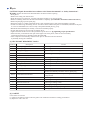
Models No.
EK7650H, EK7651H
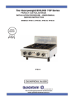
Description
Power Cutters 305mm (12"), 355mm (14")
CONCEPT AND MAIN APPLICATIONS
Models EK7650H and EK7651H are the world’s first 4-stroke power cutters.
Their main features are:
• Low fuel consumption, low noise and clean exhaust emission achieved
by 4-stroke engine
• Easy start-up with Automatic decompression, Primer pump and
Dimensions: mm (")
On/off choke combination switch with automatic half-throttle lock
EK7650H
EK7651H
• Low-vibration system with damper springs to absorb vibration from
engine to integrated front and rear handles.
Length (L)
761 (30)
780 (30-3/4)
Each wheel diameter is:
Width (W)
310 (12-1/4)
305mm (12") for model EK7650H
Height (H) 435 (17-1/8) 455 (17-7/8)
355mm (14") for model EK7651H
Specification
Specifications
Engine
Model
Type
Displacement: cm³ (cu.in)
Fuel
Max. output: kW
Max. torque: N.m
Engine oil
Fuel consumption: L/h (US oz/h)
Fuel tank capacity: L (US oz)
Rapid start
Starting (Spring-assisted recoil starter)
system
Decompression valve
Wheel diameter: mm (")
Max. cutting depth: mm (")
Dry weight*2: kg (lbs)
*1 Some countries: E10 or E25 gasoline
*2 without cutting wheel
EK7651H
EK7650H
4-stroke
75.6 (4.6)
Straight unleaded gasoline*1
3.0 (at 7,500 min.ˉ¹)
4.6 (at 5,500 min.ˉ¹)
SAE10W-30 oil
in the class SF or higher of API Classification
1.7 (57.5)
1.1 (37.2)
No
Automatic (Mechanical)
305 (12)
97 (3-13/16)
355 (14)
122 (4-13/16)
12.7 (28.0)
12.9 (28.4)
Standard equipment
Tool kit (Socket wrench 13-16, Hexalobular wrench, Slotted screwdriver and Tool bag)
Oil bottle (containing 220ml engine oil)
Water supply kit
Adapter ring (for some countries only)
Note: The standard equipment for the tool shown above may vary by country.
Optional
accessories
Filter set
Trolley kit
Oil bottle set (10 bottles of 220ml engine oil)
Diamond wheel
Abrasive cut-off wheel
P 2/ 19
Repair
CAUTION: Repair the machine in accordance with “Instruction manual” or “Safety instructions”.
Warning: Follow the instructions described below in advance before repairing:
• Wear gloves.
• Remove the cutting tool from the unit.
• When the engine is hot from use, cool down the engine enough or you can get burned.
• Remove remaining fuel from Fuel tank and Carburetor completely. [FLAMMABLE MATERIAL KEEP FIRE AWAY]
• Remove Spark plug cap from Spark plug.
• Repair the engine on a stable workbench and in a clean workplace kept as free of dust and debris as possible.
• In order to avoid wrong reassembly, draw or write down where and how the parts are assembled, and what are the parts.
It is also recommended to have boxes ready to keep disassembled parts by group.
• Handle the disassembled parts carefully. Clean and wash them properly.
• If some bolts and screws are too tight, use Impact driver.
• Tighten the bolts and the screws to the specified torque as shown in "[5] Tightening torque specifications".
• Each time after you mounted a main part of the engine such as the piston, check if it moves smoothly
without abnormal noise by manually turning the crankshaft.
• After completion of reassembly, check for loose parts or abnormal noise and vibration
by manually turning the crankshaft.
[1] NECESSARY REPAIRING TOOLS
Code No.
Description
Use for
1R003
Retaining ring pliers ST-2N for External ring removing Lock off lever
1R005
Retaining ring pliers RT-2N for Internal ring removing Cotter
1R030
Bearing setting pipe 25-17.2
1R223
Torque wrench shaft 20-90N·m
1R224
Ratchet head 12.7 (for 1R223)
1R288
1R290
1R291
1R308
Screwdriver magnetizer
Hexalobular bit VT-27 (6.35mm)
Retaining ring S and R pliers
Spring pin extractor 4.0
removing/ assembling Cotter
removing/ assembling Hexalobular bolt
removing/ installing Retaining ring R-40
removing Pin 5 from Rocker arm assembly
1R311
1R364
Retaining ring pliers
Flywheel puller
1R366
Feeler gauge set
removing Tubes
removing Flywheel
adjusting the gap between Ignition coil and Flywheel,
Rocker arm assembly and Valve section, Spark plug
1R372
Crank shaft lock bolt M10
1R389
Cotter removal attachment
holding the position of Piston/ preventing Crankshaft from
being rotated
removing Exhaust / Intake valve system
---
Socket/ Socket bit 17
removing/ installing Clutch
---
Socket/ Socket bit 24
removing/ installing Clutch
---
Wire brush
cleaning Spark plug
-----
Hex wrench 2.5
Wrench 8
assembling/ removing / adjusting M5 Hex socket head bolt
holding M5x9 Hex nut
press-fitting Ball bearing 6203LLU into Cutting device
assembling Clutch complete to Crankshaft
[2] GASKET
Once Gasket is removed:
(1) Clean up the mating surface where the gasket was installed to maintain its sealing performance.
(2) Replace it with a new one.
P 3/ 19
Repair
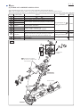
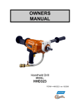
[3] LUBRICANT/ ADHESIVE APPLICATION
Apply the following grease/ oil to protect parts and product from unusual abrasion.
Note: After assembly, supply 220cc of 4-cycle engine oil from the inlet of machine before trial run.
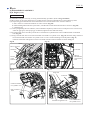
When disassembling the engine, put ThreeBond 1215 to the matching surface of Crank case and Cylinder block. (Fig. 66)
Item No.
Description
Use for
Amount
Lubricant
Retainer (2 pcs.) Contact surface with 119 and 120
109
Pin 5
Contact surface with the holes of Cylinder head assembly
112
Push rod (2 pcs.) Contact surface with the holes of Rocker arm assembly
117
Exhaust valve
119
Contact surface with the inner periphery of Valve guide
Intake valve
4-cycle Engine oil
120
a little
(API grade SM class)
Cylinder block
Contact
surface
with
Piston
123
complete
133
134
138
Cam lifter L
Cam lifter R
Oil seal 17
140
Crankshaft
complete
185
208
Oil seal L
Spiral spring
• Contact surface with Push rod
• Contact surface with Cam gear complete
Inner periphery
• Steel balls in Ball bearings 6204LU and 6204
• Hole of Connection rod to pass Piston pin in Piston
• Needle cage in the other hole of Connection rod
Inner periphery
Entire surface
Makita grease N No. 2
a little
4-cycle Engine oil
(API grade SM class)
a little
Makita grease N No. 2
a little
109
Fig. 1
112
Valve
guide
117
Cylinder head
complete
119
120
123 Cylinder block complete
(It consists of Cylinder block
and Crankcase)
Cylinder block
133
134
Starter assembly
140
Connecting
rod
138
Ball bearing
6204LU
Crankcase
185
Ball bearing
6204
208
P 4/ 19
Repair
[4] DISASSEMBLY/ASSEMBLY
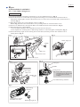
[4]-1. V-belt 5-800, Cutting device
DISASSEMBLING
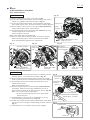
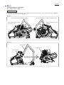
(1) Loosen two M8 Hex nuts slightly with Wrench 13-16 of a standard accessory. (Fig. 2)
(2) Release the tension on V-belt 5-800 by turning M6 Tensioning screw counterclockwise with Screwdriver.
The position of M6 square nut shows the tension level; as it comes close to the minus mark, the belt tension is
relieved. (Fig. 2)
(3) When Water supply set is on the machine, remove it. (Fig. 3)
Holder (Fig. 2) can be removed from Belt cover by turning clockwise/ counterclockwise to 90° .
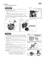
(4) Remove two M8 Hex nuts, then separate Belt cover and Hood section from the machine. (Fig. 4)
(5) When Hood section is disassembled:
1. Face the blade installation side of Spindle toward the ram of Arbor press.
2. Press Spindle out of Cutting device. Ball bearing 6203LLU is removed together with Spindle. (Fig. 5)
(6) Remove Retaining ring R-40 from Cutting device with 1R291, and then press the other 6203LLU out of
Cutting device. (Fig. 6)
Fig. 2
Fig. 3
Water supply set
Holder
M6 Square nut
Belt cover
M6 Tension screw
Minus mark
M8 Hex nut (2 pcs.)
Fig. 4
Fig. 5
Cutting device
Arbor press
Spindle
Hood section
V belt 5-800
Belt cover
M8 Hex nut
(2 pcs.)
Cutting device
Note: Another Ball bearing 6203LLU
and Retaining ring R-40 are left
in Cutting device as drawn
in Fig. 6.
One of Ball bearing 6203LLU
Fig. 6
Ball bearing
6203LLU
Cutting device viewed
from Belt cover side
Retaining ring R-40
P 5/ 19
Repair
[4] DISASSEMBLY/ASSEMBLY
[4]-1. V-belt 5-800, Cutting device (cont.)
ASSEMBLING
Assemble their parts by reversing the disassembly procedure.
(1) Assemble one of Ball bearing 6203LLU to Cutting holder, then snap Retaining ring R-40 into the groove of
Cutting device to secure the bearing.
(2) Insert Spindle into the other Ball bearing 6203LLU, then assemble them to Cutting device until they stop.
Note: Use two 1R030 as drawn in Fig. 7 so that their inner retainers of Ball bearings 6203LLU can be held without load
to the other portions.
This retains the proper tensions to their inner retainers.
(3) Insert Lock shaft into the place of Cutting device, then set Sliding disc and Impact plate. Push Lock shaft from
Belt cover side toward Blade installation side until the top bumps against Impact plate. (Fig. 8)
(4) Belt tension must be adjusted by turning M6 Tension screw clockwise until M6 Hex nut is aligned to a line between
plus mark and minus mark. (Fig. 9.)
(5) Holder of Water supply set can be set to Belt cover by turning clockwise/ counterclockwise to 90° .
Fig. 8
Fig. 7
[Belt cover side]
1R030 to hold the inner retainer
of Ball bearing 6203LLU
Impact plate
Lock shaft
Align the flat end of
Impact plate to that of
Hood complete.
1R030 to hold the inner retainer
of Ball bearing 6203LLU
Fig. 9
Holder
M6 Square nut
Belt cover
M6 Tension screw
Line
[Blade installation side]
P 6/ 19
Repair
[4] DISASSEMBLY/ASSEMBLY
[4]-2. Starter assembly
Fig. 10
DISASSEMBLING
M5x19 - Hexalobular
socket head bolt
(3 pcs.)
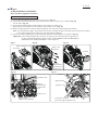
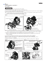
(1) Loosen three M5x19 - Hexalobular socket head bolts, then remove
Starter assembly. (Fig. 10)
(2) When Starter rope is not broken;
1. Make a slack of Starter rope then hook it on U-shaped notch of Reel.
(Fig. 11)
2. Be sure to loosen the spiral spring force by turn Reel clockwise to spin
Starter rope around Reel before the step (3). (Fig. 11)
(3) Loosen M6x20 Set screw with Phillips screwdriver No. 3. (Fig. 11)
(4) When Reel is removed from Starter case, insert a index finger carefully to
the reverse side of Reel and then remove Reel from Starter case with
Spiral spring attached. (Fig. 12.)
Fig. 11
Starter assembly (gray portion)
Fig. 12
Starter case
U-shaped
notch of Reel
Reel
Hold Spiral spring
by an index finger.
Starter rope
Reel
M6x20 Set screw
ASSEMBLING
(1) If Spiral spring pops out of Reel, put it back in place by setting
the outer end of Spiral spring in place in Reel first, then by winding
Spiral spring counterclockwise towards the center of Reel. (Fig. 13)
(2) Apply a little amount of Makita grease N No.2 to the whole surface
of Spiral spring.
(3) Put Starter rope through Starter case complete.
After passing the one end through Starter knob and Rope stopper,
tie the end as drawn in Fig. 14. Then cover the top of Starter knob
with Cap.
After passing the other end from the hole of Starter case to Reel,
tie the end in Reel.
(4) Wind Starter rope around Reel for the 2/3 length (When the whole
length is 1m, wind 66cm.)
(5) While setting the inner end of Spiral spring into the center slot of
Starter case, assemble Reel to Starter case properly.
(6) Tighten M6x20 Set screw with Phillips screwdriver No. 3. (Fig. 11)
(7) Make a slack of Starter rope then hook it on U-shaped notch of
Reel. (Fig. 11) Turn Reel counterclockwise to spin Starter rope
around Reel.
Important: Make sure that the proper spring force is effective to Starter
assembly by turning Starter knob by hand and it can be
returned back to the original position. (Fig. 15)
Even if Starter rope is pulled to the full, there is room to
rotate Reel because of Spiral spring performance.
Spiral spring
Fig. 13
Reel
Set the outer end of
Spiral spring here.
Spiral spring
Fig. 14
Cap
Rope stopper
Starter knob
Hole of Starter case
Fig. 15
P 7/ 19
Repair
[4] DISASSEMBLY/ASSEMBLY
[4]-3. Clutch, Ratchet
DISASSEMBLING
Fig. 16
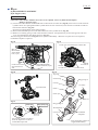
(1) Remove Cutting device. Refer to the clause of [4]-1.
(2) Loosen three M5x12 Hexalobular socket head bolts, then remove
Clutch cover together with Starter assembly. (Fig. 16)
(3) Loosen three M5x16 Hexalobular socket head bolts with 1R290
Clutch cover
and Cordless impact driver, and remove Ratchet complete. (Fig. 17)
(4) Remove M10-17 Hex lock nut by turning it counterclockwise by
Starter
using Cordless impact driver with Socket bit.
assembly
(5) Turn the hexagonal portion of Clutch holder clockwise by using
U-shaped notch
Cordless impact driver with Socket bit.
of Reel
Clutch complete is removed.
Note: Clutch holder has a left hand thread.
(6) Remove Clutch drum assembly by hand. No tools are required.
Remove Retaining ring R-35 from Clutch drum with 1R005.
M5x12 Hexalobular socket
Press down Ball bearing 6003LLU in Clutch drum.
head bolt (3 pcs.)
Fig. 17
Ratchet complete
M5x16 Hexalobular
socket head bolt (3 pcs.)
Fig. 18
M10-17
Hex lock
nut
Fig. 19
Hexagonal
portion (M16-24)
of Clutch holder
17mm flats width
Socket bit
24mm flats width
Socket bit
ASSEMBLING
(1) Put Spacer 17 and Clutch drum assembly to Crankshaft, then put Fig. 20
Crankshaft
the other Spacer 17 on Clutch drum assembly. (Fig. 20)
(2) Remove Spark plug and assemble 1R372 carefully to Cylinder
Spacer 17
block by hand to prevents Crankshaft from being rotated. (Fig. 21)
Clutch drum
(3) Turn Flywheel slowly and carefully by hand until the top of
assembly
1R372 contacts Piston.
Spacer 17
Note: Do not damage Piston.
(4) Turn the hexagonal portion of Clutch holder counterclockwise
with 1R223, 1R224 and 17mm flat width Socket in order to
tighten Clutch complete to the fastening torque 38N.m. (Fig. 20)
Note: • Do not use Cordless impact driver.
Clutch complete
• Do not turn the hexagonal portion with 1R372 taken
24mm flats width Socket
apart from Piston.
(Square drive: 12.7mm)
(5) Assemble M10-17 Hex lock nut to Crankshaft by reversing
the disassembling procedure shown in Fig. 18.
(6) Set Ratchet complete and three M5x16 Hexalobular socket head 1R224 1R223
bolts in place by reversing the disassembling procedure shown in Fig. 21
Fig. 17.
Cylinder block
(7) Assemble the rest in accordance with the clause of [4]-1.
1R372
Piston
P 8/ 19
Repair
[4] DISASSEMBLY/ASSEMBLY
[4]-4. Flywheel, Ignition coil
Fig. 22
DISASSEMBLING FLYWHEEL COMPLETE
(1) Loosen four M5x30 - Hexalobular socket head bolts, then remove
Fan cover. (Fig. 22)
(2) Remove M10 Flange nut from Crankshaft by turning counterclockwise
by using Cordless impact driver with 14mm flats width Socket bit.
(Fig. 23)
(3) Mount 1R364 on Flywheel complete, then put Screwdriver through
the center shaft of IR364. (Fig. 24)
(4) While holding the one of M6 bolts and center bolt with Water pump pliers
to prevent 1R364 from being rotated, turn Screwdriver clockwise.
When Flywheel is removed from Crankshaft, a snap sound is heard
because of their tapered fit.
Fig. 24
Fig. 23
14mm flats width
Socket bit
M10 Flange nut
M5x30 - Hexalobular socket
head bolt (4 pcs.)
Center bolt of 1R364
M6 bolt of 1R364
Crankshaft
Flywheel
Water pump
pliers
Screwdriver
ASSEMBLING FLYWHEEL COMPLETE
Fig. 25
(1) Remove grease from Crankshaft complete.
(2) After aligning the key slot of Flywheel complete with
Woodruff key in the keyway of Crankshaft complete,
mount Flywheel complete onto Crankshaft complete.
(Fig. 25)
(3) Assemble the rest by reversing the disassembly procedure.
Woodruff key
in key way of
Crankshaft complete
Key slot of
Flywheel complete
ADJUSTMENT THE GAP BETWEEN IGNITION COIL AND FLYWHEEL
0.3 up to 0.4mm is the proper gap between Ignition coil and Flywheel.
Refer to Fig. 26 and the following steps.
(1) Loosen two M5x16 Hexalobular socket head bolts on Ignition coil.
(2) Insert 0.3mm leaf of 1R366 between Ignition coil and the magnet of
Flywheel complete.
Ignition coil will be attracted to the magnet through the Feeler gauge.
Then, without removing the Feeler gauge, fasten Ignition coil to
the engine with two M5x16 Hexalobular socket head bolts.
First tighten 1 , the next, tighten 2 . The order is easy to keep
the proper gap.
(2) Remove 1R366. Then make sure that Flywheel complete does not
touch Ignition coil by turning it by hand.
Fig. 26
M5x16 Hexalobular socket head bolt
(2 pcs.)
1
2
0.3 up to
0.4mm
0.3mm leaf of 1R366
P 9/ 19
Repair
[4] DISASSEMBLY/ASSEMBLY
[4]-4. Flywheel, Ignition coil (cont.)
DISASSEMBLING IGNITION COIL
(1) Loosen M6x15 Thumb screw, then remove Top cover. (Fig. 27)
(2) Loosen four M5x40 Hexalobular socket head bolts, then remove Filter cover complete (Fig. 28)
and Air filter. (Fig. 29)
(3) Loosen M5x16 Hexalobular socket head bolt, then remove Cylinder cover.
Remove Plug cord of Ignition coil assembly from Cylinder cover. (Fig. 30)
(4) Remove Flag terminal on Lead unit end from Ignition coil with care to the breaking of Lead unit.
Note: It is recommend to apply “the principle of leverage.” Without being forced to pull, put the long noses of Pliers
on the edge of Ignition coil and lever up the flag terminal. (Fig. 31)
(5) Loosen two M5x16 Hexalobular socket head bolts, and then remove Ignition coil. Refer to Fig. 26.
Important: Unless the disassembling is necessary for repair, do not touch the bolts of Ignition coil.
In case of disassembling them, the hard work “ADJUSTMENT THE GAP BETWEEN
IGNITION COIL AND FLYWHEEL” will be required.
Fig. 28
Fig. 27
Fig. 29
M6x15 Thumb screw
Filter cover
complete
Top cover
Air filter
M5x40
Hexalobular
socket head
bolt (4 pcs.)
Fig. 30
Fig. 31
Lead unit
Cylinder cover
Flag terminal
M5x16
Hexalobular
socket head
bolt
Ignition coil
Ignition coil
Plug cord of
Ignition coil assembly
Long noses of Pliers
put on the edge of Ignition coil
P 10/ 19
Repair
[4] DISASSEMBLY/ASSEMBLY
[4]-5. Carburetor
Fig. 32
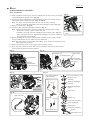
(1) After completion of the steps (1) and (2) on [4]-4, remove Grip cover by loosening
5.5x20 Hexalobular tapping screw. (Fig. 32)
(2) Loosen two M5x45 Hexalobular socket head bolts, then remove Carburetor and
Filter gasket from Carburetor mount. (Figs. 33 and 34)
Note: Use 1R311 to hold/ pinch Tubes to lever it up for easy removing.
Grip cover
Do not use the sharp edged Pliers that causes damage to Tubes. (Fig. 35)
(3) Remove Contact spring. (Fig. 36)
(4) Carburetor WT can be disassembled as shown in Fig. 37.
Note: • Check the components’ shrinkage, hardening or breakage due to aged
deterioration. If any, replace it with a new one.
5.5x20 Hexalobular tapping
• Carburetor for some countries is different from Carburetor WT. (Fig. 37)
screw
The components cannot be supplied individually because of the regulation
for compliance with standards.
(5) Before mounting the inner parts of Pump body assembly in place, make sure that
the tip of Inlet needle valve is neither worn nor deformed.
Note: The inner parts are not available individually. If you need some of the inner parts,
order Pump body assembly.
(6) Make sure that Inlet screen is not clogged, then set it back in place.
(7) Spray carburetor cleaner in all the fuel lines of Carburetor, then after several minutes,
wash out dirt and debris with clean gasoline.
Fig. 33
Fig. 34
Carburetor WT
Filter bracket
Carburetor gasket
Filter bracket
M5x45 Hexalobular socket head
bolt (2 pcs.)
M5x45
Hexalobular
socket head bolt
Fig. 35
Throttle linkage
(2 pcs.)
Fig. 37
Inner parts of Pump
body assembly
Metering lever pin
1R311
Tube
Screw
Screw assembly (4 pcs.)
Metering cover
assembly
Metering diaphragm
assembly
Metering diaphragm
gasket
The shape edges
damage Tubes.
Inlet screen
Fig. 36
Tank complete
Metering
lever
Spring
Limiter cap
Pump body assembly
Pump diaphragm
Pump gasket
Contact spring
Inlet needle valve
Pump body assembly
Spring
Idle adjust screw
Screw
P 11/ 19
Repair
[4] DISASSEMBLY/ASSEMBLY
[4]-5. Carburetor (cont.)
ADJUSTMENT OF CARBURETOR AFTER REPLACEMENT
Pull throttle lever fully after a while engine running at idle position. When there is Fig. 38
a problem with the engine quick acceleration, adjust H needle (Fig. 38) as follows:
(1) Warm up the engine by pulling the throttle lever fully for one minute.
(2) Keep engine idling and do fine adjustment of the idling speed by turning
H needle (Fig. 38) with a thin slotted screwdriver.
(3) Pull the throttle lever quickly. If Engine stall happens/ Engine does not reach
the maximum rpm, do step (4). If there are no problems with the engine quick
acceleration, go ahead to step (5).
(4) Unscrew H needle 1/8 turn (45°) with a thin slotted screwdriver.
Adjust H needle through the hole
After pulling the throttle lever fully with no load, retry the step (3).
near H mark with a thin slotted
(5) Push two Limiter caps (Fig. 37) into Carburetor with a flat top of rod.
screwdriver.
Note: It is not necessary to touch L needle.
ASSEMBLING
Fig. 39
Assemble by reversing the disassembly procedure. Be careful to the following points.
Sponge
• Align the ends of Sponge sleeve 9 and Breather on Tube 3-190. (Fig. 39)
sleeve 9
• Set Breather in place so that Tube 3-190 is fixed to the rib in Tank complete. (Fig. 40)
Breather
• Set Tubes, Choke linkage and Throttle linkage in place. (Fig. 41) Be careful to each
direction of the linkages.
Tube 3-190
Fig. 40
Fix the assembled part
drawn in Fig. 39 with
Lead wire holder in
Tank complete
Fig. 41
Tube 3-45 between Hose joint
and Carburetor
Perspective view
Lead unit (A)
Lead unit (B) between Contact
spring and Ignition oil
Carburetor
Hose joint
Tube 3-35 from
Hose joint to
Filter bracket
Tube 3-300 between
Carburetor and
Gasoline filter in
Tank complete
Lead unit (A) must be routed
under these ribs.
Tube 3-190
(Refer to Fig. 39.)
Contact spring on Lead unit
(B) end must be inserted
into these notches of ribs.
Tube 3-120 between
Primer pump and
Grommet on
Tank complete
Plate on Switch lever
Choke linkage Throttle linkage
Tube 3-190 between
Primer pump and
Carburetor
(Refer to Fig. 39.)
P 12/ 19
Repair
[4] DISASSEMBLY/ASSEMBLY
[4]-6. Throttle lever
Fig. 42
DISASSEMBLING
(1) Remove Pin 5 from the grooves on Tank complete by levering it up with a
slotted screwdriver. (Fig. 42)
(2) Expand the hinge portion for Throttle lever on Tank complete with 1R003.
(Fig. 43)
Throttle lever section can be removed as drawn in Fig. 44.
Fig. 43
Pin 5
Fig. 44
1R003
Pin 5
Throttle lever
Lock off lever
Expand the hinge portion carefully.
Torsion
spring 12
[4]-7. Engine block
DISASSEMBLING
Note: • It is highly recommended to drain the oil system of Engine block before starting disassembling
because the oil remaining there will drip out to delay your operation.
• When Piston section is repaired, it is necessary to remove Engine from Tank complete.
(1) Remove Hood section. Refer to Fig. 4 of [4]-1.
(2) Remove Carburetor. Refer to [4]-5.
Refer to Fig. 45 and do the following steps (3), (4), (5).
(3) Remove three Tubes’ ends that come from Cylinder block complete as follows:
• Tube 3-170 with Clamp to Rocker cover
• Tube 3-130 to Hose joint in Seal
• Tube 3-75 to Hose joint in Seal
(4) Remove Tube 5-70 with Clamp from Rocker cover.
(5) Loosen Hose clamp 30 then remove Suction line from Cylinder block complete.
Fig. 45
Tube 3-170
with Clamp
Rocker cover
Tube 5-70
with Clamp
Tube 3-130
Suction line
Seal with Joints
Tube 3-75
Cylinder block
Hose clamp 30
P 13/ 19
Repair
[4] DISASSEMBLY/ASSEMBLY
[4]-7. Engine block (cont.)
DISASSEMBLING
(6) Remove four M6x30 Hexalobular socket head bolts that fasten Front handle, Tank complete and Engine. (Fig. 46)
Engine block can be removed. (Fig. 47)
Fig. 46
[Viewed from Blade installation side]
[Viewed from Starter assembly installation side]
M6x30 Hexalobular socket
head bolt (3 pcs.)
M6x30 Hexalobular socket
head bolt
Fig. 47
Front handle
Engine block
Tank complete
P 14/ 19
Repair
[4] DISASSEMBLY/ASSEMBLY
[4]-8. Engine
DISASSEMBLING
(1) Remove Clutch complete and Clutch drum. Refer to [4]-3.
(2) Remove Flywheel. Refer to [4]-4. If necessary, remove Ignition coil.
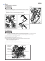
(3) Loosen five M6x25 Hexalobular socket head bolts, then remove Cutting arm from Cylinder block complete. (Fig. 48)
(4) Remove Exhaust muffler from Cylinder block complete.
Note: Although Spark arrester can be removed from Exhaust muffler, it is not permitted to replace Spark arrester only
because it functions as the integrated part with Exhaust muffler.
(5) Remove Oil case from Cylinder block complete. (Fig. 49)
Fig. 48
Fig. 49
Exhaust
muffler
Cylinder head
complete
Cylinder block complete
Cylinder block
Crank case
Spark arrester
M6x25 Hexalobular
socket head bolt (5 pcs.)
Cylinder
block
complete
Oil case
M5x16 Hexalobular
socket head bolt (4 pcs.)
Cutting arm
Note: Unless you repair Exhaust valves, Cam lifters, and Rocker arms, do the following steps. It is not necessary to
remove Cylinder block from Crank case (Fig. 49)/ Carburetor from Cylinder block complete (Refer to Fig. 34.)
(6) Remove two M6x20 Hexalobular socket head bolts on the upper side of Exhaust muffler.
Remove two M5x25 Hexalobular socket head bolts then separate Rocker cover complete from Cylinder head
complete. (Fig. 50)
(7) Loosen Hose clamp then remove Suction line from Cylinder head complete. (Refer to Fig. 41)
(8) Remove Cylinder head complete from Cylinder block, then pull out two Push rods. (Fig. 51)
Note: Do not failure to mix them up. It is recommend to distinguish Exhaust push-rod and Intake push-rod.
(9) Remove Cam gear cover (Fig. 52).
(10) Remove Cam lifter L and Cam lifter R. Then, remove Cam gear complete by pulling out Pin 5. (Fig. 53)
Fig. 50
Fig. 51
Rocker cover
M6x35 Hexalobular socket
M5x25 Hexalobular
complete
head bolt (4 pcs.)
socket head bolt
(2 pcs.)
Cylinder head complete
M6x20 Hexalobular
socket head bolt
(2 pcs.)
Do not touch this M6x20
Hexalobular socket
head bolt.
Fig. 52
Fig. 53
Cam lifter L
Cam gear cover
M5x16
Hexalobular
socket head
bolt (4 pcs.)
Push rod (for exhaust system)
Push rod (for intake system)
Cylinder block
Cam lifter R
Cam gear assembly
Cam gear
Fly weight
complete
Cam gear plate
Pin 5
Torsion spring 9
P 15/ 19
Repair
[4] DISASSEMBLY/ASSEMBLY
[4]-8. Engine (cont.)
DISASSEMBLING
Note: Cam gear assembly functions as automatic decompression valve system.
Valve is slightly open to release the compressed air in Engine at the starting time, before moving fly weight
by centrifugal effects. It means the insufficient setting of Cam gear assembly will cause engine stall/ extreme
reaction force at engine running due to too much load by the compressed air.
(11) Remove Pin 5 that sets Rocker arm assembly in place on Cylinder head complete. (Fig. 54)
Use 1R308 to push out Pin 5.
The distinction of Rocker arm assembly and Push rods (for use of the exhaust system/ intake system) enables you
shortens the repair process (Gap adjustment between Rocker arms and Retainers is even difficult, however, you can
adjust it by using 1R366. Refer to Fig. 68.
Fig. 54
the hole of Cylinder head complete
Rocker arm assembly
Pin 5
Exhaust
system
Cylinder head
complete
Exhaust
push-rod
Intake
system
Intake
push-rod
Note: Intake system of Rocker
arm has to be close to
the hole of Cylinder head
complete.
Important: Disassemble the parts in the room on Cylinder head complete before removing it and
clean the clogged portions in the following steps. You may repair successfully without
doing the step (5) and later in the next page.
(1) Remove Rocker cover complete, then push out Pin 5 on hinge for Rocker arms with 1R308 and remove Rocker arms.
(Refer to Figs. 50 and 54)
(2) Remove Spark plug. Turn Flywheel until Piston comes to the upper dead point by looking through Spark plug hole
on Cylinder head complete.
Note: Align the rib as a mark on Flywheel with the rib on Cylinder block as drawn in Fig. 55.
(3) Insert a bent Lead wire #16 into Combustion chamber through Spark plug hole so that Valves do not fall into
Combustion chamber. (Fig. 56)
(4) While compressing Compression spring 11 by pushing Retainer with 1R003 attached with 1R389, remove Cotter by
a thin bit magnetized by 1R288.
Routes in Cylinder head complete, the upper surface on Valves and the room on Cylinder head complete can be clean
through removal of four Cotters, two Retainers, and two Compression springs 11.
Fig. 55
Fig. 57
Rib on Cylinder block
Retainer (2 pcs.)
Cotter (4 pcs.)
Compression
spring 11 (2 pcs.)
Cylinder head complete
Rib on Flywheel
Fig. 56
Use Cotter removal
attachment to push
Retainer.
1R389
1R003
Note: Intake valve has to
be close to this hole
of Cylinder head
complete.
Intake valve
[viewed from the upper side of the room]
Exhaust valve
P 16/ 19
Repair
[4] DISASSEMBLY/ASSEMBLY
[4]-8. Engine (cont.)
DISASSEMBLING
Important: When Intake/ Exhaust valves have to be replaced, remove Cylinder head complete.
(Refer to previous page.)
(5) Loosen eleven Hexalobular socket head bolts on the bottom of Crank case (Fig. 58), then remove Crank case from
Cylinder block. As Liquid gasket makes Cylinder block stick on Crank case, insert and twist a slotted screwdriver
between the clearance. (Fig. 59)
Scrape away Liquid gasket on the mating surface.
(6) Pull out the assembled part of Crank shaft and Piston from Cylinder block. (Fig. 60)
(7) Remove one of Ring spring 12 with a thin slotted screwdriver, then push Piston pin from the opposite with care
so as not to damage the other Ring spring 12. (Fig. 61)
The following parts mentioned in Fig. 62 can be replaced individually. When the rest parts have to be replaced,
Crankshaft complete is required.
Fig. 58
Fig. 59
Crank case viewed from the bottom side
M5x16
Hexalobular
socket head
bolt (3 pcs.)
M6x30 Hexalobular
socket head bolt (8 pcs.)
Crank case viewed
from the bottom
side
Slotted
screwdriver
Slotted
screwdriver
Cylinder block
Fig. 62
Fig. 60
Top ring
Second ring
Ring spring 12
Oil ring
Oil seal L
Cylinder block
Piston
Piston pin
Flat washer 41
Fig. 61
Piston pin
Ring spring 12
Ring spring 12
Woodruff key 4
Piston
Insert a thin slotted screwdriver
from the depression on the rib
around Piston pin hole.
Oil seal 17
Crankshaft
complete*
*The components cannot be
supplied individually.
P 17/ 19
Repair
[4] DISASSEMBLY/ASSEMBLY
[4]-8. Engine (cont.)
ASSEMBLING ENGINE BLOCK
Note: Be sure to apply Makita grease N No.2/ 4-cycle engine oil in accordance with [3] LUBRICANT APPLICATION.
(1) Connect Piston with Crankshaft complete by inserting Piston pin into place; there is no front/back to Piston.
(2) Secure Piston pin by mounting Ring spring 12 onto each end of Piston pin.
Note: The ring gap of Ring spring 12 can be positioned at any angle to Piston pin.
(3) Install Oil ring in the grooves of Piston; Side rail first, Spacer next, then the other Side rail.
Important: Be sure to fit the three rings with the ring gaps at 120 degrees to one another as shown in the left of Fig. 63.
(4) Install Second ring first then Top ring in the groove of Piston.
Important 1: Be sure to fit the two rings with the ring gaps at 180 degrees to each other as shown in the right of Fig. 63.
Important 2: Second ring has a taper face and must be installed with the large diameter facing Oil ring. (Fig. 64)
Distinguishing between Top ring and Second ring & Discriminating the larger diameter of Second ring:
If both of the two rings are new and unused,
• You can distinguish from their appearances; there is a red marking on the side face of Second ring as shown in
Fig. 65 while not on the side face of Top ring.
• You can face the large diameter of Second ring by placing Second ring with the red marking on your right and
with the ring gap near you as shown in Fig. 65.
If both of the two rings are used and the white marking of Second ring is rubbed off, carefully press the side face of
the two rings to the inner wall surface of Cylinder. You will be able to distinguish the two rings or to discriminate the
large diameter of Second ring through the differences in contact feelings that the different side faces make.
(4) Remove oil/grease from the mating surface of Cylinder block and Crankcase.
Then apply ThreeBond 1215 to the mating surface of Crankcase as shown in Fig. 66.
Note: ThreeBond 1215 must not be applied to Oil supply routes.
Apply 4-cycle engine oil to the cylinder portion of Cylinder block, and then while compressing Piston rings, mount
Cylinder block onto Crankcase.
(6) Tighten eleven Hexalobular socket head bolts in a crisscross pattern. (Refer to Fig. 58.)
(7) Do not forget to set Exhaust port spacer in place on Muffler installation side of Cylinder head complete. (Fig. 67)
Fig. 63
ring gap
Oil ring
ring gap
Top ring
Side rail
Second ring
ring gap
Spacer
Side rail
ring gap
This mark can be
ignored for
assembling
EK7650H/ EK7651H.
ring gap
Fig. 64
Fig. 65
Top ring,
with barrel face
Second ring,
with taper face
Side rail
Spacer
Side rail
Oil ring
Second ring
red marking
Fig. 66 [Crankcase viewed from top]
Fig. 67
Portion to apply
ThreeBond:
indicated in gray
Oil supply routes
Cylinder head complete
Exhaust port spacer
P 18/ 19
Repair
[4] DISASSEMBLY/ASSEMBLY
[4]-8. Engine (cont.)
DISASSEMBLING
(8) Assemble Cam gear section by reversing the disassembly procedure. (Refer to Fig. 53 and 52.)
(9) Move Piston to the upper dead point in Cylinder block by turning Crankshaft slowly and carefully by hand.
(10) Adjust the gap between Rocker arms and Exhaust valve section/ Intake valve section as follows:
A. Put 0.1mm or 0.15mm leaf of 1R366 on Valve section. (Fig. 68)
B. While holding M5x9 Hex nut by Wrench 8, turn M5 Hex socket head bolt with Hex wrench 2.5. (Fig. 68)
C. Check the gap.
(11) After pretightening the nuts and bolts, turn Crankshaft complete by hand to move Crank portion two or three turns,
check the gap again, if the proper gap is obtained, tighten the nuts and bolts firmly.
(12) Lead unit that comes from Stop switch has to be fastened to Cylinder block with 6x30 Hexalobular socket head
bolt. (Fig. 69)
(13) Plug cord and Tube have to be fixed with Lead wire holders on Cylinder cover. (Fig. 70) And then, Plug cord has to
be fixed with Lead wire holders on Cylinder cover to route it without slacking toward Flywheel. (Fig. 71)
Lead unit connected with Ignition coil has to be fixed with the Lead wire holders as drawn in Fig. 71.
Fig. 68
Fig. 69
1R366
Hex wrench 2.5
Wrench 8
Lead unit
M5 Hex
socket
head bolt
M6x30
Hexalobular
socket head
bolt
M5x9
Hex nut
Fig. 70
Fig. 71
Plug cord
Lead unit
Lead wire holders
on Cylinder cover
Plug cord and
Tube
Terminal of Ignition coil
Lead wire holders
on Cylinder cover
P 19/ 19
Repair
[4] DISASSEMBLY/ASSEMBLY
[4]-9. Ignition system (cont.)
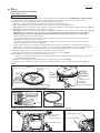
CHECKING SPARK PLUG
WARNING !!
• When a spark is produced, high-voltage current is delivered from Ignition coil to Spark plug.
It is, therefore, very dangerous to pull Recoil starter knob with your hand on Ignition cable.
Be sure to keep your hands off from Ignition cable when checking for spark.
• Fuel is extremely flammable and fuel vapors are explosive.
Therefore, clean up spilled fuel before starting to check for spark.
Also, be careful not to do the check near Carburetor.
(1) Remove Plug cap from Spark plug, then Spark plug from Cylinder head complete with the supplied socket wrench.
Note: If the electrodes of Spark plug are wet, wipe them with a rag then dry them with an air blower.
(2) Using a wire brush, carefully clean up carbon deposits (if any) from the electrodes and the ceramic insulator around
the center electrode.
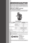
(3) Adjust the electrode gap to 0.5mm by carefully bending the side electrode. Fig. 42
Use Feeler gauge set (1R366) to check the gap width:
between the center electrode and the side electrode, insert 0.5mm leaf
side electrode
of Feeler gauge set. (Fig. 42)
(4) Install another Spark plug into spark plug hole to prevent air/fuel mixture
from leaking outside of engine.
Electrode gap
must be 0.5mm.
(5) Connect the removed Spark plug with Plug cap, then ground the threads
of Spark plug to a proper metal part of the engine.
(6) With Stop switch on, pull Recoil starter knob gently and check for spark.
center electrode
Note: It is hard to see the spark in a bright location.
Therefore, be sure to do the check in a shady but well-ventilated place.
(7) If spark is not produced, replace Spark plug with a new one,
then check for spark by following the procedure (1) to (6) once again.
[5] Tightening torque specifications
Application
(for fastening A to B)
A
1
2
3
B
Cushion
Cutting arm
Cutting arm
Tank complete
Cylinder block complete
Belt cover
Front inner holder
4
Fastener
Tightening
torque (N.m)
M6x30 Hexalobular socket head bolt
M6x25 Hexalobular socket head bolt
M8 Hex nut
30
M6x30 Hexalobular socket head bolt
3
7
5
Crank case
Cylinder block
M6x30 Hexalobular socket head bolt
12
6
7
Cylinder head complete
Flywheel
Cylinder block
Crankshaft
M6x35 Hexalobular socket head bolt
M10 Flange nut
12
40
Hexagonal portion (M16-24) of Clutch holder
38
18
6
8 Clutch holder
9 Clutch assembly
10 Rocker arm
Crankshaft
Crankshaft
M5 Hex socket head bolt
M10-17 Hex lock nut
M5x9 Hex nut