1
1750068-001B
Trademarks
KONICA MINOLTA and the KONICA MINOLTA logo are trademarks or registered
trademarks of KONICA MINOLTA HOLDINGS, INC.
QCOLOR and magicolor are trademarks or registered trademarks of KONICA
MINOLTA PRINTING SOLUTIONS U.S.A., INC.
Proprietary Statement
The digitally encoded software included with your printer is Copyright © 2004
KONICA MINOLTA BUSINESS TECHNOLOGIES, INC. All Rights Reserved. This
software may not be reproduced, modified, displayed, transferred, or copied in
any form or in any manner or on any media, in whole or in part, without the
express written permission of KONICA MINOLTA BUSINESS TECHNOLOGIES,
INC.
Copyright Notice
Copyright © 2004 KONICA MINOLTA BUSINESS TECHNOLOGIES, INC.,
Marunouchi Center Building, 1-6-1 Marunouchi, Chiyoda-ku, Tokyo, 100-0005,
Japan. All Rights Reserved. This document may not be copied, in whole or part,
nor transferred to any other media or language, without written permission of
KONICA MINOLTA BUSINESS TECHNOLOGIES, INC.
Manual Notice
KONICA MINOLTA BUSINESS TECHNOLOGIES, INC. reserves the right to make
changes to this manual and to the equipment described herein without notice.
Considerable effort has been made to ensure that this manual is free of
inaccuracies and omissions. However, KONICA MINOLTA BUSINESS
TECHNOLOGIES, INC. makes no warranty of any kind including, but not limited
to, any implied warranties of merchantability and fitness for a particular purpose
with regard to this manual. KONICA MINOLTA BUSINESS TECHNOLOGIES, INC.
assumes no responsibility for, or liability for, errors contained in this manual or for
incidental, special, or consequential damages arising out of the furnishing of this
manual, or the use of this manual in operating the equipment, or in connection
with the performance of the equipment when so operated.
2
CONTENTS
3
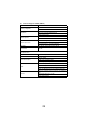
CONTENTS .................................................................3
SAFETY .......................................................................9
Safety Precautions for Inspection and Service .................................................. 11
Warning ....................................................................................................... 11
Caution ........................................................................................................ 13
Used Batteries Precautions ......................................................................... 15
Other Precautions ........................................................................................ 16
Precautions for Service ................................................................................ 16
Safety information ........................................................................................ 19
Laser Safety Label ....................................................................................... 22
Laser Caution Label ..................................................................................... 22
PRECAUTIONS FOR HANDLING THE LASER EQUIPMENT ................... 23
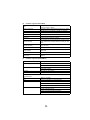
GENERAL ..................................................................25
Product Specifications ........................................................................................ 27
Installation Precautions ...................................................................................... 31
Installation environment ............................................................................... 31
Installation power supply ............................................................................. 31
Space requirements...................................................................................... 32
Operation Precautions ....................................................................................... 33
Ensuring the optimum performance of this unit ........................................... 33
Operating environment ................................................................................ 33
Power supply requirements ......................................................................... 33
Other precautions ........................................................................................ 33
Parts Identification ....................................................................................... 34
MECHANICAL/ ELECTRICAL ...................................35
CROSS-SECTIONAL VIEW ............................................................................... 37
ELECTRICAL COMPONENTS LAYOUT ........................................................... 38
OPERATING SEQUENCE ................................................................................. 43
IMAGE STABILIZATION CONTROL ................................................................. 44
AIDC Detection ............................................................................................ 44
Outline of AIDC Control ............................................................................... 45
Operation Timing ......................................................................................... 46
Temperature/Humidity Sensor ..................................................................... 47
ATVC (Auto Transfer Voltage Control ......................................................... 48
DRUM CARTRIDGE .......................................................................................... 49
PC Drum ...................................................................................................... 49
PC Drum Charging ...................................................................................... 50
LASER EXPOSURE .......................................................................................... 51
DEVELOPING UNIT .......................................................................................... 53
Developing Position ..................................................................................... 55
Toner Cartridge ............................................................................................ 56
IMAGE TRANSFER ........................................................................................... 60
Image Transfer Belt Unit .............................................................................. 60
Second Image Transfer Roller Cleaning ...................................................... 63
Image Transfer Belt Cleaning Mechanism................................................... 64
Waste Toner Bottle ...................................................................................... 66
5
Waste Toner Bottle Detection ..................................................................... 66
FUSING SECTION ............................................................................................ 67
Fusing Unit .................................................................................................. 67
Fusing Temperature Control ....................................................................... 69
PAPER TAKE-UP SECTION ............................................................................. 71
Manual Feed Tray ....................................................................................... 71
Lower Feeder Unit (Option) ......................................................................... 72
OTHER MECHANISMS ..................................................................................... 73
Duplex Unit (Option) .................................................................................... 73
MAINTENANCE & DISASSEMBLY/ASSEMBLY .......81
Disassembly/Assembly Precautions .................................................................. 83
Precautions for disassembly and assembly ................................................ 83
Parts that must not be touched ................................................................... 83
Precautions for transporting or storing PWBs ............................................. 83
Precautions for replacing PWBs .................................................................. 83
Precautions for inspecting PWBs ................................................................ 83
Precautions for transporting or storing the OPC drum cartridge ................. 84
Precautions for handling the OPC drum cartridge ....................................... 84
Red painted Screws .................................................................................... 84
Variable Resistors on Board ........................................................................ 84
Maintenance Schedule ...................................................................................... 85
Guideline for Life Specifications Values by Unit........................................... 87
Detail of Each Unit Life ................................................................................ 87
Maintenance And Cleaning ............................................................................... 89
Replacement of the Units .................................................................................. 93
Disassembly Procedures ............................................................................. 96
Pre-disassembly preparation ....................................................................... 98
Removal Of Circuit Boards And Other Electrical Components ................. 100
Removal of Units ....................................................................................... 106
DISASSEMBLY OF THE ENGINE PARTS ............................................... 111
CONTROL PANEL / SERVICE MODE DESCRIPT. 127
Control Panel Descriptions—2300DL & 2350 ................................................. 129
Names of control panel parts and their functions ...................................... 129
Message Window ...................................................................................... 129
Menu Contents for magicolor 2300 DL ............................................................ 133
Print menu overview .................................................................................. 133
Settings menus .......................................................................................... 134
Service Mode ............................................................................................ 136
Service mode displays .............................................................................. 136
Entering service mode .............................................................................. 136
Service mode options ................................................................................ 136
Menu Contents for magicolor 2350 ................................................................. 138
Menu Overview ......................................................................................... 138
About the 2300W Control Panel ...................................................................... 140
Control Panel Key ..................................................................................... 140
Indicator Lights .......................................................................................... 141
Working with the 2300W Status Display ................................................... 142
6
Using the Status Display ............................................................................ 143
Status, Error and Service Messages ......................................................... 144
TROUBLESHOOTING .............................................147
Introduction ...................................................................................................... 149
Checking the electrical components .......................................................... 149
Paper Misfeeds ................................................................................................ 152
Perform initial check procedures ............................................................... 152
Paper misfeed displays .............................................................................. 153
Wiring diagram of misfeed-detecting sensors ............................................ 154
Misfeed detection timing and remedies ..................................................... 155
Malfunctions and Warnings (2300 DL & 2350) ................................................ 159
Malfunction detection timing and remedies ............................................... 161
Power supply malfunctions ........................................................................ 167
Image Quality Troubleshooting ........................................................................ 168
INDEX ......................................................................171
7
8
SAFETY
9
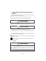
1.
SAFETY PRECAUTIONS FOR INSPECTION AND
SERVICE
• When performing inspection and service procedures, observe the following precautions
to prevent accidents and ensure utmost safety.
✽ Depending on the model, some of the precautions listed below do not apply.
• Different markings are used to denote specific meanings as detailed below.
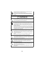
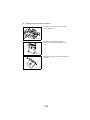
WARNING
• Indicates a potentially hazardous situation which, if not avoided, may result in minor or
moderate injury. It may also be used to alert against unsafe practices.
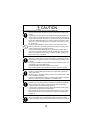
CAUTION
• Indicates a potentially hazardous situation whech, if not avoided, may result in minor or
moderate injury. It may also be used to alert against unsave practices.
• The following graphic symbols are used to give instructions that need to be observed.
Used to call the service technician attention to what is graphically represented
inside the marking (including a warning).
Used to prohibit the service technician from doing what is graphically represented
inside the marking.
Used to instruct the service technician to do what is graphically represented
inside the marking.
1-1.
Warning
WARNING
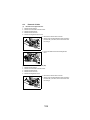
1. Always observe precautions.
• Parts requiring special attention in this product include a label containing the
mark shown on the left plus precautionary notes. Be sure to observe the precautions.
• Be sure to observe the “Safety Information” given in the user documentation.
2. Before starting the procedures, be sure to unplug the power cord.
11
• This product contains a high-voltage unit and a circuit with a large current
capacity that may cause an electric shock or burn.
• The product also contains parts that can jerk suddenly and cause injury.
• If this product uses a laser, laser beam leakage may cause eye damage or
blindness.
WARNING
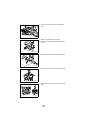
3. Do not throw toner or the toner bottle into a fire.
• Do not throw toner or the Toner Bottle (Imaging Cartridge, Toner Cartridge) into
a fire. Toner expelled from the fire may cause burns.
4. Use the specified parts.
• For replacement parts, always use the genuine parts specified in the manufacturer’s parts manual. Installing a wrong or unauthorized part could cause
dielectric breakdown, overload, or undermine safety devices resulting in possible electric shock or fire.
• Replace a blown electrical fuse or thermal fuse with its corresponding genuine
part specified in the manufacturer’s parts manual. Installing a fuse of a different
make or rating could lead to a possible fire. If a thermal fuse blows frequently,
the temperature control system may have a problem and action must be taken
to eliminate the cause of the problem.
5. Handle the power cord with care and never use a multiple outlet.
• Do not break, crush or otherwise damage the power cord. Placing a heavy
object on the power cord, or pulling or bending it may damage it, resulting in a
possible fire or electric shock.
• Do not use a multiple outlet to which any other appliance or machine is connected.
• Be sure the power outlet meets or exceeds the specified capacity.
6. Be careful with the high-voltage parts.
• A part marked with the symbol shown on the left carries a high voltage. Touching it could result in an electric shock or burn. Be sure to unplug the power cord
before servicing this part or the parts near it.
7. Do not work with wet hands.
• Do not unplug or plug in the power cord, or perform any kind of service or
inspection with wet hands. Doing so could result in an electric shock.
8. Do not touch a high-temperature part.
• A part marked with the symbol shown on the left and other parts such as the
exposure lamp and fusing roller can be very hot while the machine is energized. Touching them may result in a burn.
• Wait until these parts have cooled down before replacing them or any surrounding parts.
12
WARNING
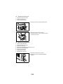
9. Maintain a Grounded Connection at all times.
• Connect the power cord to an electrical outlet that is equipped with a grounding terminal.
10. Do not remodel the product.
• Modifying this product in a manner not authorized by the manufacturer may
result in a fire or electric shock. If this product uses a laser, laser beam leakage
may cause eye damage or blindness.
11. Restore all parts and harnesses to their original positions.
• To promote safety and prevent product damage, make sure the harnesses are
returned to their original positions and properly secured in their clamps and
saddles in order to avoid hot parts, high-voltage parts, sharp edges, or being
crushed.
• To promote safety, make sure that all tubing and other insulating materials are
returned to their original positions. Make sure that floating components
mounted on the circuit boards are at their correct distance and position off the
boards.
1-2.
Caution
CAUTION
1. Precautions for Service Jobs.
• A star washer and spring washer, if used originally, must be reinstalled. Omitting them may result in contact failure which could cause an electric shock or
fire.
• When reassembling parts, make sure that the correct screws (size, type) are
used in the correct places. Using the wrong screw could lead to stripped
threads, poorly secured parts, poor insulating or grounding, and result in a malfunction, electric shock or injury.
• Take great care to avoid personal injury from possible burrs and sharp edges
on the parts, frames and chassis of the product.
• When moving the product or removing an option, use care not to injure your
back or allow your hands to be caught in mechanisms.
13
CAUTION
2. Precautions for Servicing with Covers and Parts Removed.
• Wherever feasible, keep all parts and covers mounted when energizing the
product.
• If energizing the product with a cover removed is absolutely unavoidable, do
not touch any exposed live parts and use care not to allow your clothing to be
caught in the moving parts. Never leave a product in this condition unattended.
• Never place disassembled parts or a container of liquid on the product. Parts
falling into, or the liquid spilling inside, the mechanism could result in an electric shock or fire.
• Never use a flammable spray near the product. This could result in a fire.
• Make sure the power cord is unplugged before removing or installing circuit
boards or plugging in or unplugging connectors.
• Always use the interlock switch actuating jig to actuate an interlock switch
when a cover is opened or removed. The use of folded paper or some other
object may damage the interlock switch mechanism, possibly resulting in an
electric shock, injury or blindness.
3. Precautions for the Working Environment.
• The product must be placed on a flat, level surface that is stable and secure.
• Never place this product or its parts on an unsteady or tilting workbench when
servicing.
• Provide good ventilation at regular intervals if a service job must be done in a
confined space for a long period of time.
• Avoid dusty locations and places exposed to oil or steam.
• Avoid working positions that may block the ventilation ports of the product.
4. Precautions for Handling Batteries. (Lithium, Nickel-Cadmium, etc.)
• Replace a rundown battery with the same type as specified in the manufacturer’s parts manual.
• Before installing a new battery, make sure of the correct polarity of the installation or the battery could burst.
• Dispose of used batteries according to the local regulations. Never dispose of
them at the user’s premises or attempt to try to discharge one.
5. Precautions for the Laser Beam. (Only for Products Employing a Laser)
• Removing the cover marked with the caution label could lead to possible exposure to the laser beam, resulting in eye damage or blindness. Be sure to
unplug the power cord before removing this cover.
• If removing this cover while the power is ON is unavoidable, be sure to wear
protective laser goggles that meet specifications.
• Make sure that no one enters the room when the machine is in this condition.
• When handling the laser unit, observe the “Precautions for Handling Laser
Equipment.”
6. Precautions for storing the toner or imaging cartridge.
• Be sure to keep the toner or imaging cartridge out of the reach of children.
Licking the imaging cartridge or ingesting its contents is harmful to your health.
14
1-3.
Used Batteries Precautions
ALL Areas
CAUTION
Danger of explosion if battery is incorrectly replaced.
Replace only with the same or equivalent type recommended by the manufacturer.
Dispose of used batteries according to the manufacturer’s instructions.
Germany
VORSICHT!
Explosionsgefahr bei unsachgemäßem Austausch der Batterie.
Ersatz nur durch denselben oder einen vom Hersteller empfohlenen gleichwertigen Typ.
Entsorgung gebrauchter Batterien nach Angaben des Herstellers.
France
ATTENTION
Il y a danger d’explosion s’il y a remplacement incorrect de la batterie.
Remplacer uniquement avec une batterie du même type ou d’un type équivalent recommandé par le constructeur.
Mettre au rebut les batteries usagées conformément aux instructions du fabricant.
Denmark
ADVARSEL!
Lithiumbatteri - Eksplosionsfare ved fejlagtig håndtering.
Udskiftning må kun ske med batteri af samme fabrikat og type.
Levér det brugte batteri tilbage til leverandøren.
Finland, Sweden
VAROlTUS
Paristo voi räjähtää, jos se on virheellisesti asennettu.
Vaihda paristo ainoastaan laitevalmistajan suosittelemaan tyyppiin.
Hävitä käytetty paristo valmistajan ohjeiden mukaisesti.
VARNING
Explosionsfara vid felaktigt batteribyte.
Använd samma batterityp eller en ekvivalent typ som rekommenderas av apparattillverkaren.
Kassera använt batteri enligt fabrikantens instruktion.
Norway
ADVARSEL
Eksplosjonsfare ved feilaktig skifte av batteri.
Benytt samme batteritype eller en tilsvarende type anbefalt av apparatfabrikanten.
Brukte batterier kasseres i henhold til fabrikantens instruksjoner.
15
1-4.
Other Precautions
• When handling circuit boards, observe the “HANDLING of PWBs”.
• The PC Drum is a very delicate component. Observe the precautions given in “HANDLING OF THE PC DRUM” because mishandling may result in serious image problems.
• Note that replacement of a circuit board may call for readjustments or resetting of particular items, or software installation.
1-5.
Precautions for Service
• When performing inspection and service procedures, observe the following precautions
to prevent mishandling of the machine and its parts.
✽ Depending on the model, some of the precautions given in the following do not apply.
1. Precautions Before Service
• When the user is using a word processor or personal computer from a wall outlet of the
same line, take necessary steps to prevent the circuit breaker from opening due to overloads.
• Never disturb the LAN by breaking or making a network connection, altering termination,
installing or removing networking hardware or software, or shutting down networked
devices without the knowledge and express permission of the network administrator or
the shop supervisor.
2. How to Use this Book
DIS/REASSEMBLY, ADJUSTMENT
• To reassemble the product, reverse the order of disassembly unless otherwise specified.
TROUBLESHOOTING
• If a component on a PWB or any other functional unit including a motor is defective, the
text only instructs you to replace the whole PWB or functional unit and does not give troubleshooting procedures applicable within the defective unit.
• All troubleshooting procedures contained herein assume that there are no breaks in the
harnesses and cords and all connectors are plugged into the right positions.
• The procedures preclude possible malfunctions due to noise and other external causes.
3. Precautions for Service
• Keep all disassembled parts in good order and keep tools under control so that none will
be lost or damaged.
• After completing a service job, perform a safety check. Make sure that all parts, wiring
and screws are returned to their original positions.
• Do not pull out the toner hopper while the toner bottle is turning. This could result in a
damaged motor or locking mechanism.
• If the product is to be run with the front door open, make sure that the toner hopper is in
the locked position.
• Do not use an air gun or vacuum cleaner for cleaning the ATDC Sensor and other sensors, as they can cause electrostatic damage. Use a blower brush and cloth. If a unit
containing these sensors is to be cleaned, first remove the sensors from the unit.
16
4. Precautions for Dis/Reassembly
• Be sure to unplug the printer from the outlet before attempting to service the printer.
• The basic rule is not to operate the printer anytime during disassembly. If it is absolutely
necessary to run the printer with its covers removed, use care not to allow your clothing
to be caught in revolving parts such as the timing belt and gears.
• Before attempting to replace parts and unplug connectors, make sure that the power
cord of the printer has been unplugged from the wall outlet.
• Be sure to use the Interlock Switch Actuating Jig whenever it is necessary to actuate the
Interlock Switch with the covers left open or removed.
• While the product is energized, do not unplug or plug connectors into the circuit boards
or harnesses.
• Never use flammable sprays near the printer.
• A used battery should be disposed of according to the local regulations and never be discarded casually or left unattended at the user’s premises.
• When reassembling parts, make sure that the correct screws (size, type) and toothed
washer are used in the correct places.
5. Precautions for Circuit Inspection
• Never create a closed circuit across connector pins except those specified in the text and
on the printed circuit.
• When creating a closed circuit and measuring a voltage across connector pins specified
in the text, be sure to use the GND wire.
6. Handling of PWBs
During Transportation/Storage
• During transportation or when in storage, new P.W. Boards must not be indiscriminately
removed from their protective conductive bags.
• Do not store or place P.W. Boards in a location exposed to direct sunlight and high temperature.
• When it becomes absolutely necessary to remove a Board from its conductive bag or
case, always place it on its conductive mat in an area as free as possible from static electricity.
• Do not touch the pins of the ICs with your bare hands.
• Protect the PWBs from any external force so that they are not bent or damaged.
During Inspection/Replacement
• Avoid checking the IC directly with a multimeter; use connectors on the Board.
• Never create a closed circuit across IC pins with a metal tool.
• Before unplugging connectors from the P.W. Boards, make sure that the power cord has
been unplugged from the outlet.
• When removing a Board from its conductive bag or conductive case, do not touch the
pins of the ICs or the printed pattern. Place it in position by holding only the edges of the
Board.
• When touching the PWB, wear a wrist strap and connect its cord to a securely grounded
place whenever possible. If you cannot wear a wrist strap, touch a metal part to discharge static electricity before touching the PWB.
• Note that replacement of a PWB may call for readjustments or resetting of particular
items.
7. Handling of Other Parts
• The magnet roller generates a strong magnetic field. Do not bring it near a watch, floppy
disk, magnetic card, or CRT.
17
8. Handling of the Imaging Cartridge
During Transportation/Storage
• The storage temperature is in the range between –20 °C and +40 °C.
• In summer, avoid leaving the Imaging Cartridge in a car for a long time.
Handling
• Store the Imaging Cartridge in a place that is not exposed to direct sunlight.
Precautionary Information on the PC Drum Inside the Imaging Cartridge
• Use care not to contaminate the surface of the PC Drum with oil-base solvent, fingerprints, and other foreign matter.
• Do not scratch the surface of the PC Drum.
• Do not attempt to wipe clean the surface of the PC Drum.
18
1-6.
(1)
Safety information
Laser Safety
• This is a digital machine certified as a class 1 laser product. There is no possibility of
danger from a laser, provided the machine is serviced according to the instruction in this
manual.
(2)
Internal Laser Radiation
semiconductor laser
Maximum average radiation power(*)
4.68 µW
Wavelength
770-795 nm
*:Laser power in surface of the PC Drum
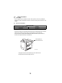
• This product employs a Class 3b laser diode that emits an invisible laser beam. The laser
diode and the scanning polygon mirror are incorporated in the print head unit.
• The print head unit is NOT A FIELD SERVICE ITEM. Therefore, the print head unit
should not be opened under any circumstances.
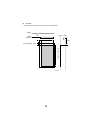
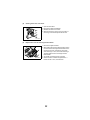
Laser Aperture of
the Print Head Unit
C4131o001AA
This figure shows the view inside the Top Cover with the Toner
Cartridge and the Drum Cartridge removed.
19
the U.S.A., Canada
(CDRH Regulation)
• This machine is certified as a Class I Laser product under Radiation Performance Standard according to the Food, Drug and Cosmetic Act of 1990. Compliance is mandatory
for Laser products marketed in the United States and is reported to the Center for
Devices and Radiological Health (CDRH) of the U.S. Food and Drug Administration of
the U.S. Department of Health and Human Services (DHHS). This means that the device
does not produce hazardous laser radiation.
• The label shown to page 13 indicates compliance with the CDRH regulations and must
be attached to laser products marketed in the United States.
.
CAUTION
Use of controls, adjustments or performance of procedures other than those specified in
this manual may result in hazardous radiation exposure.
semiconductor laser
Maximum power of the laser diode
5 mW
Wavelength
770-795 nm
All Areas
CAUTION
Use of controls, adjustments or performance of procedures other than those specified in
this manual may result in hazardous radiation exposure.
semiconductor laser
Maximum power of the laser diode
5 mW
Wavelength
770-795 nm
Denmark
ADVARSEL
Usynlig laserstråling ved åbning, når sikkerhedsafbrydere er ude af funktion.
Undgå udsættelse for stråling. Klasse 1 laser produkt der opfylder IEC60825 sikkerheds
kravene.
halvlederlaser
Laserdiodens højeste styrke
5 mW
bølgelængden
770-795 nm
20
Finland, Sweden
LUOKAN 1 LASERLAITE
KLASS 1 LASER APPARAT
VAROITUS!
Laitteen käyttäminen muulla kuin tässä käyttöohjeessa mainitulla tavalla saattaa altistaa
käyttäjän turvallisuusluokan 1 ylittävälle näkymättömälle lasersäteilylle.
puolijohdelaser
Laserdiodin suurin teho
5 mW
aallonpituus
770-795 nm
VARNING!
Om apparaten används på annat sätt än i denna bruksanvisning specificerats, kan
användaren utsättas för osynlig laserstrålning, som överskrider gränsen för laserklass 1.
halvledarlaser
Den maximala effekten för laserdioden
5 mW
våglängden
770-795 nm
VARO!
Avattaessa ja suojalukitus ohitettaessa olet alttiina näkymättomälle lasersäteilylle. Älä
katso säteeseen.
VARNING!
Osynlig laserstråining när denna del är öppnad och spärren är urkopplad. Betrakta ej
stråien.
Norway
ADVERSEL
Dersom apparatet brukes på annen måte enn spesifisert i denne bruksanvisning, kan
brukeren utsettes för unsynlig laserstrålning, som overskrider grensen for laser klass 1.
halvleder laser
Maksimal effekt till laserdiode
5 mW
bølgelengde
770-795 nm
21
1-7.
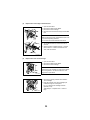
Laser Safety Label
• A laser safety label is attached to the outside of the machine as shown below.
for 120V
for 220 - 240V
for 100V
4131o003AA
1-8.
Laser Caution Label
• A laser caution label is attached to the inside of the machine as shown below.
C4131s005AA
22
1-9.
PRECAUTIONS FOR HANDLING THE LASER EQUIPMENT
• When laser protective goggles are to be used, select ones with a lens conforming to the
above specifications.
• When a disassembly job needs to be performed in the laser beam path, such as when
working around the printerhead and PC Drum, be sure first to turn the printer OFF.
• If the job requires that the printer be left ON, take off your watch and ring and wear laser
protective goggles.
• A highly reflective tool can be dangerous if it is brought into the laser beam path. Use
utmost care when handling tools on the user’s premise.
23
24
GENERAL
25
1.
(1)
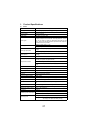
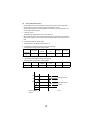
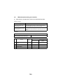
Product Specifications
Printer
Type
Desktop full-color laser beam printer
Printing method
Electrophotographic (two-part imaging cartridge)
Exposure method
Laser diode and polygon mirror scanning
Print resolution
600 dpi (dots/inch)
Media sizes
A5T, B5T, A4, Letter, Legal
Media types
Plain paper (16-24 lb bond, 60-90 g/m2), recycled paper, overhead
projector transparencies, letterheads, envelopes (Monarch, Com-10,
DL, C5, C6, Chokei -3, Chokei -4), label sheets, thick paper (91-163
g/m2), government-standard postcards, postcard sheets, Japanese
postcard, and return postcards
First-page print time
Multi-page print speed
Black-and-white printing: 14 sec.
Color printing: 25 sec.
Black-and-white printing: 16 pages/min. (for A4- or Letter-size
pages)
Color printing: 4 pages/min. (for A4- or Letter-size pages)
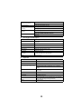
Warm-up time
System speed
Within 180 seconds (at a room temperature of 23 °C and at the rated
voltage)
101.78 mm/sec.
1-way system (maximum 2-way); Expandable to 2-way system by
installing the optional 2nd paper cassette
Paper feed-in method
Manual feed tray (200 sheets of plain paper)
2nd paper cassette (500 sheets of plain paper) (2300 DL & 2350
only)
Paper feed-out method
Face-down (tray capacity: 200 sheets)
Drum-charging method
Comb electrode scorotron charger
Developing method
Single-element developing system
Image transfer method
Transport image transfer system
PC drum
OPC (Organic Photoconductor)
PC drum cleaning method
Blade system
Paper separation method
Curvature separation + charge-neutralizing system
Fusing method
Heated roller fusing system
Dimensions
14.02 in.(356 mm) (W) x 19.69 in.(500 mm) (D) x 15.43 in. (392 mm)
(H)
Weight
55.1 lbs(25 kg) (without drum cartridge and toner cartridges)
Weight (consumables)
62.4 lbs (28.3 kg) (including drum cartridge and toner cartridges)
Rated power supply voltage
100 V / 120V / 220-240 V
Frequency
50/60 Hz
Maximum power consumption
1100 W or less (100/120 V)
1100 W or less (220-240 V)
During stand-by: 39 dB (A) or less
Operating noise
During printing: 54 dB (A) or less (color printing)
54 dB (A) or less (black-and-white printing)
27
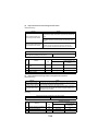
Operating environment
50-95° F (10-35°C)
15 - 85%
Drum cartridge life
45,000 pages (black/white ratio=5%)
Toner cartridge life (purchased
separately)
4,500 pages (black/white ratio=5%)
Toner cartridge life (enclosed
cartridge)
Black: 1,500 pages (black/white ratio=5%)
Options
(2)
1,500 pages (black/white ratio=5%)
Color: 1,500 pages (color/white ratio for each color=5%)
Second paper cassette (2300 DL & 2350 only)
Duplex unit
Second paper cassette (Option)
Name
Second paper cassette (2300 DL & 2350 only)
Paper
Plain paper (16 to 24 lbs.; 60-90 g/m2), recycled paper (16 to 24 lbs.,
60-90 g/m2)
Media sizes
A4, Letter
Paper cassette capacity
500 sheets
Paper separation mechanism
Paper separator system
Power source
Supplied by main unit (DC24 V ±10%)
Drive source
Supplied by main unit
Dimensions
15 in. (380 mm) (W) x 20.1 in. (511 mm) (D) x 6.9 in. (176 mm) (H)
(including the height of the right-side door)
Weight
11.7 lbs. (5.3 kg)
(3)
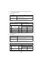
Duplex unit
Name
Duplex unit
Paper
Plain paper (16 to 24 lbs.; 60-90 g/m2)
Media sizes
A4, Letter
Color printing: 2.0 pages/min. (A4- or Letter-size pages)
Print speed (double-sided printing)
Document feeding capacity
Black-and-white printing: 5.0 pages/min. (A4- or Letter-size
pages)
A4/Letter: 2 pages (including the paper path of the paper feedout section)
Paper transfer baseline
Center baseline
Power source
Supplied by main unit (DC24 V ±10%)
Drive source
Supplied by main unit
Dimensions
3.8 in. (97 mm) (W) x 13.4 in. (340 mm) (D) x 13 in. (330 mm)
(H) (including the height of the right-side door)
Weight
4.4 lbs. (2.0 kg)
28
(4)
Controller magicolor 2300DL (PWB-P)
CPU
Memory configuration
D8405 200MHz
Standard ROM: 4MB
Standard RAM: 32MB
Ethernet (10/100BASE-TX, RJ-45)
Standard I/F
IEEE1284 (Compatible/Nibble/ECP/EPP)
USB Type B connector
Network protocol
TCP/IP
DHCP, ARP/ICMP, BOOTP, SLP, IPP, HTTP, SNMP, LPR
RAW Port Printing (9100)
Network print service
IPP1.0 (http://Printer IP address/ipp.cgi)
Resolution
600 x 600 dpi, 1200 x 600 dpi, 2400 x 600 dpi
Printer Driver
OS: Windows 95/98/Me, Windows NT4.0, Windows 2000, Windows XP
LPD (Queue Name: lp, LP, default, DEFAULT)
Compatible clients:
PC
CPU
IBM PC or compatible
CPU clock of 300 MHz or more recommended
Minimum 36 MB
Hard disk free space
20 MB: Printer drive/Status display
16 MB: Image processing area
At least 16 MB (Windows 95/98/NT4.0)
RAM
At least 32 MB (Windows Me)
At least 64 MB (Windows 2000 Professional)
At least 128 MB (Windows XP Home Edition/Professional)
Browser
Either of the following browsers is required to use PageScope
Light.
Netscape Navigator Ver. 4.7 or later
Internet Explorer ver5.0
29
(5)
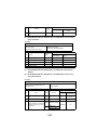
Controller magicolor 2350 (PWB-P)
IBM Mercury, Power PC 405, 200 Mhz processor core SOC,
system bus speed of 100 Mhz
CPU
Memory configuration
Boot ROM (512KB); 12MB Flash ROM (supports up to 24MB)
128 MB standard, upgreadeable to 384 MB via 1 DIMM slot
Standard I/F
Ethernet (10/100BASE-TX, RJ-45)
IEEE1284 (Compatible/Nibble/ECP/EPP)
USB 1.1
Optional I/F
Dongle (803.11b & Bluetooth) via parallel
Optional Hard Disk
IDE Hard Disk Kit (includes daughterboard, hard disk and TOD
clock); IDE Hard Disk Kit (without hard disk) for third party hard
disks.
Resident Emulations
PostScript 3, PCL 5, XL, PDF v. 1.3 (requires optional hard
disk), Line printer
Fonts
137 PostScript fonts, 90 PCL fonts (80 scalable & 10 bitmap)
System Software
Upgradable via FLASH at initial release, later upgradeable via
Mask ROM.
Resolution
600 x 600 dpi, 1200 x 600 dpi, 2400 x 600 dpi
Printer Driver
OS: Windows 95/98/Me, Windows NT4.0, Windows 2000, Windows XP
(6)
Controller magicolor 2300W (PWB-P)
CPU
Memory configuration
N1-chip (Naltec original ASIC)
64 KB (In ASIC)
Standard RAM: 32MB
Standard I/F
IEEE1284 (Compatible/Nibble/ECP)
USB Type B connector
Resolution
600 x 600 dpi, 1200 x 600 dpi
Printer Driver
OS: Windows 95/98/Me, Windows 2000, Windows XP
Compatible clients:
PC
IBM PC or compatible
CPU
CPU clock of 300 MHz or more recommended
Hard disk free space
Minimum 256 MB
128 MB: Printer drive/Status display
128 MB: Image processing area
RAM
At least 16 MB (Windows 95/98)
At least 32 MB (Windows Me)
At least 64 MB (Windows 2000 Professional)
At least 128 MB (Windows XP Home Edition/Professional)
30
2.
2-1.
Installation Precautions
Installation environment
To ensure safety and prevent possible malfunctions, install the unit in a location that meets
the following requirements.
• A location that is not exposed to extremely high or low temperatures and not exposed to
extremely high or low humidity.
• A location that is not exposed to extreme changes in temperature or humidity.
• A location that is not exposed to direct sunlight.
• A location out of the direct airflow of an air conditioner, heater or ventilation opening.
• A well-ventilated location that is not extremely dusty.
• A stable and level location that is not subjected to undue vibrations.
• A location that is not near room heaters or any other heat-generating appliances.
• A location away from volatile, combustible material (such as paint thinner or gasoline).
• A location that is not exposed to water or other liquids and where a short circuit of the
unit is not likely.
• A location that does not put people in the direct airflow of exhaust from the unit.
• A location where ammonia gases are not generated.
2-2.
Installation power supply
• If other electrical equipment are plugged into the same electrical outlet, make sure that
the current capacity is not exceeded.
• Use a power source with as little voltage fluctuations as possible.
• Only use an outlet expander or a table tap; never use extension cords.
• Be careful that the unit does not pinch or is not placed on top of power or transmission
cords of other electrical equipment.
• Periodically check that the following conditions are met:
✽The power supply plug does not feel unusually warm.
✽The power supply cord is free of cracks and scratches.
✽The power supply plug is securely inserted into the electrical outlet.
✽Pressure is not applied to the power supply cord.
31
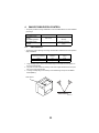
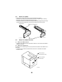
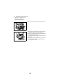
2-3.
Space requirements
15.4 in. (390 mm)
23.2 in (590 mm)
•
13.4 in. (340 mm)
5.9 in.
(150 mm)
27.8 in. (705 mm)
4131o103AA
19.7 in.
(500 mm)
27.6 in.
(700 mm)
11.8 in.
(300 mm)
C4131o105AA
32
3.
3-1.
•
•
•
•
•
•
•
•
•
•
•
•
•
Operation Precautions
Ensuring the optimum performance of this unit
Never place heavy objects on the unit or subject it to shocks.
Make sure that the power supply plug is securely inserted into the electrical outlet.
Never remove secured panels or open doors of the unit while it is printing.
Never turn off the unit while it is printing.
Always provide good ventilation when using the unit for a long period of time within a
confined area.
Never use combustible sprays near the unit.
If the unit becomes unusually warm or generates an unusual noise, immediately turn it
off, and then unplug the power supply cord.
Never turn on the unit at the same time that the power supply cord is being plugged in.
When unplugging the power supply cord, always grasp the plug, not the cord.
Never bring magnetized objects near the unit.
Never place vases or other containers filled with liquid on the unit.
Be sure to turn off the unit if it is not to be used for a long period of time or if a power outage occurs.
Never allow metal objects such as paper clips or staples to fall into the unit or any of its
openings.
3-2.
Operating environment
In order to ensure proper operation of the unit, make sure that the operating environment
meets the following conditions:
• Temperature: 50-95° F (10-35 °C)
• Humidity: 15-85% Rh
• Temperature fluctuation: ±18° F (10 °C) per hour
• Humidity fluctuation: ±20% Rh per hour
3-3.
Power supply requirements
In order to ensure proper operation of the unit, make sure that the power supply meets the
following conditions:
• Voltage fluctuation ±10% of the specified voltage
• Frequency fluctuation ±3 Hz%
• In order to reduce the risk of electric shock in the event of a short circuit, the ground wire
must be connected.
• Attach the ground wire to the ground terminal of the electrical outlet or to a ground connection that complies with local electrical standards.
• Never connect the ground wire to a gas pipe, a telephone ground connection, a lightning
rod or a water pipe, otherwise a fire or electric shock may occur.
3-4.
Other precautions
When servicing a machine equipped with a laser beam, observe the following precautions:
• When servicing parts in the path of the laser beam (near the print head or PC drum), be
sure to first unplug the power supply cord of the unit.
• When you are required to service the unit with the power supply cord plugged in, be sure
to strictly observe the following precautions:
1. Before performing any service procedures, be sure to remove any reflective accessories such as watches and rings, and wear laser protective goggles.
2. Be sure that nobody is nearby while you perform the service operations.
3. Do not bring highly reflective tools into the path of the laser beam.
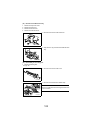
33
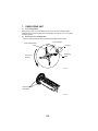
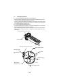
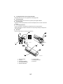
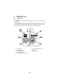
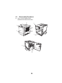
3-5.
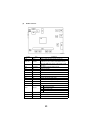
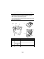
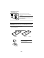
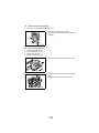
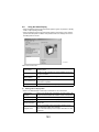
Parts Identification
3
4131o001AA
4
2
4131o106AA
1
4131g002AA
5
4131g003AA
6
7
8
4131g004AA
4131o107AA
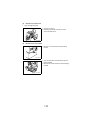
1.
Manual feed tray
2.
Power switch
3.
Image transfer belt unit
4.
Waste toner bottle
5.
Drum cartridge
6.
Toner cartridge
7.
Right-side door release lever
8.
Duplex unit (optional)
34
MECHANICAL/
ELECTRICAL
35
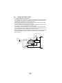
1.
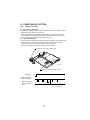
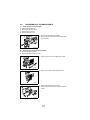
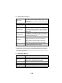
CROSS-SECTIONAL VIEW
4
3
5
2
6
7
1
K
C
Y
8
M
9
10
4131M001AA
8. Transport Roller
9. Paper Take-Up Roller
10. Second Paper Take-Up
Roller
1.
2.
3.
4.
5.
6.
Toner Cartridge Rack
PC Drum
Image Transfer Belt Unit
Exit Roller
Fusing Roller
Second Image Transfer
Roller
7. Synchronizing Roller
✽ Paper Path
The printer has a Multi-Purpose Tray (MPT) capable of holding up to 200 sheets of paper.
Paper feeding becomes a two-way system by mounting an optional feeder unit.
• The paper pulled by the Paper Take-Up Roll is transported by the Transport Roller, Synchronizing Roller, Second Image Transfer Roller, Fusing Roller, and the Exit Roller and
fed out of the printer.
37
2.
(1)
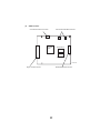
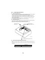
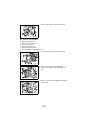
ELECTRICAL COMPONENTS LAYOUT
Printer
36
37
35
33
31
38
34
32
1
2
3
30
4
5
6
29
28
26
7
8
9
10
11
25
12
27
24
23
13
22
21 20
14
19
18
15
17
16
38
4131D002AA
1. Fusing Roller Heater Lamp (H1)
2. Fusing Pressure Roller Heater Lamp
(H2)
3. Thermistor (TH1)
4. Thermostat (TS1)
5. Second Image Transfer Roller Pressure Contact Solenoid (SL5)
6. Fusing Cooling Fan Motor (M5)
7. Synchronizing Roller Solenoid (SL3)
8. Fusing Paper Loop Detecting Sensor
(PC11)
9. Transport Roller Solenoid (SL2)
10. Right Door Switch (S3)
11. Paper Transport Sensor (PC12)
12. Waste Toner Bottle Set Switch (S5)
13. Second Image Transfer Roller Pressure Positioning Sensor (PC7)
14. Waste Toner Full Detecting Sensor
(PC6)
15. OHP Detecting Sensor (PC3A)
16. Synchronizing Roller Sensor (PC2)
17. Laser Safety Switch (S4)
18. Front Door Switch (S2)
19. Manual Feed Paper Empty Sensor
(PC1)
20. Manual Feed Paper Take-Up Solenoid (SL1)
21. Temperature/Humidity Sensor (HS1)
22. Power Unit (PU)
23. Power Switch (S1)
24. Toner Cartridge Detecting Sensor
(PC8)
25. High Voltage Unit (HV)
26. Rack Home Position Sensor (PC4)
27. Belt Cleaner Separation Solenoid
(SL4)
28. Rack Clutch (CL1)
29. Belt Cleaner Positioning Sensor
(PC9)
30. Rack Motor (M2)
31. AIDC Sensor (AIDC)
32. Main Motor (M1)
33. Master Board (PWB-A)
34. Power Supply Cooling Fan Motor
(M4)
35. Ventilation Fan Motor (M6)
36. Fusing Paper Loop Solenoid (SL6)
37. Print Head Unit (PH)
38. Exit Sensor (PC10)
39
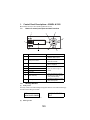
(2)
2300DL Controller
4131M039AA
Symbol
Item
Explanation
U18
CPU
Destiny D8405 200 MHz controller control CPU
U26, U27,
U28, U29
SDRAM
8-MB memory chip, a total of 32 MB standard memory
CON4
Expansion slot
68-pin SD-RAM add-on memory (128, 256 MB, PC100/
133 CL3)
CN1
Connector
10/100Base-T Ethernet RJ45 connector
U3
IC
Ethernet Controller
CN3
Connector
USB connector
U12
IC
USB Controller
CN5
Connector
IEEE1284 Parallel Connector
U21
IC
Parallel buffer
U6
IC
System data storage ROM (4 MB)
U5
ASIC
JBIG compressed image processing
CON1
Connector
Controller Panel expansion connector
CN2
Connector
SW1
Dip SW
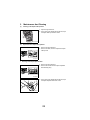
Engine Controller connector
1.
Not Used (Always OFF)
2.
Not Used (Always OFF)
3.
ON: A4, OFF: Letter
4.
ON: A4, OFF: Letter
CR7
LED
For 5 V voltage check
CR10
LED
For 3.3 V voltage check
CN6
Connector
Video signal connector
40
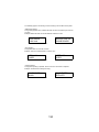
(3)
2350 Controller
U4
U17
J6
TP2
U15
J1
J12
J13
U9
J16
J2
JP10
U13
J4
J15
J7
J17
U3
Symbol
U6
U10
U12
U16
Item
U19
U24
U30
Explanation
U13
CPU
200 MHz Power PC 405 CPU
U3, U6, U10,
U12, U16,
U19, U24, U30
SDRAM
A total of 128 MB standard memory
J7
Expansion slot
68-pin SD-RAM add-on memory (128, 256 MB, PC100/
133 CL3)
J15
Connector
10/100Base-T Ethernet RJ45 connector
J16
Connector
IEEE1284 Parallel Connector
J17
Connector
USB connector
JP10
Jumper
DIAG test point
J2
Jumper
DEBUG test point
J1
Connector
Engine I/F
TP2
Test Point
5V
J12
Connector
PCI Daughterboard Card Bus
J13
Connector
PCI IDE Hard Drive Card Bus
U9
IC
FPGA1
U15
IC
FPGA PROM
U17
IC
DSFL PROM
J6
Connector
Controller Panel connector
J4
Connector
Printhead Video signal connector
U4
Socket
Empty PROM Socket
41
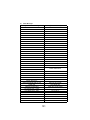
(4)
2300W Controller
Controller Panel Interface Connector
Demonstration ROM Board Connector
Controller
ASIC
Image memory
Image memory
4131M554AA
Engine Controller connector
Parallel/USB Interface Connector
42
43
Manual Feed Paper
Take-Up Solenoid (SL1)
Belt Cleaner Separator
Solenoid (SL4)
Second Image Transfer Roller
Pressure Contact Solenoid (SL5)
Second Image Transfer Output
First Image Transfer Output
Transport Roller Solenoid (SL2)
Synchronizing Roller
Solenoid (SL3)
Synchronizing Roller Sensor (PC2)
Exposure Output
PC Drum Charge Output
Rack Motor (M2)
Main Motor (M1)
FD Scanning Signal (/TOD)
Image Transfer Belt
Positioning Sensor (PC5)
Polygon Motor (M3)
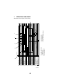
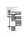
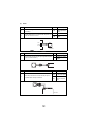
1
Retraction
1. Outside image area
illumination
2. Y development
3. M development
Print Request
2
Pressure
1
3
Pressure
Retraction
Retraction
5
4. C development
5. Bk development
6. Paper trailing edge voltage
Pressure
4
6
3.
OPERATING SEQUENCE
✽ Conditions: A4 plain paper, full-color printing
4131M043AA
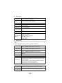
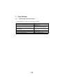
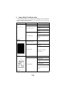
4.
IMAGE STABILIZATION CONTROL
• The printer provides the image stabilization control as detailed below to ensure stabilized
print image.
Purpose
Control
Control (Sensor)
AIDC control
AIDC Sensor (AIDC
detection)
Image transfer output control
Temperature/Humidity
Sensor
• To stabilize image
density
• To stabilize gradation
• To stabilize image
transfer
4-1.
AIDC Detection
• The amount of toner sticking to the Image Transfer Belt is measured and color reproducibility is stabilized.
Intensity of Light
Reflected
Output
Large
Low
Small
Small
High
Great
Amount of Toner Sticking
1. A light-emitting diode is used to emit infrared rays that illuminate the toner pattern on
the Image Transfer Belt.
2. The photo receiver detects the intensity of the infrared light reflected off the toner pattern on the Image Transfer Belt.
3. A voltage corresponding to the intensity of the reflected light is output to the Master
Board (PWB-A).
AIDC Sensor
4004M532AA
44
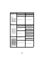
4-2.
Outline of AIDC Control
• The following AIDC controls are provided to ensure image stabilization.
Control
Description
• Ds correction control
• Sets the developing bias.
• LED intensity adjustment
control
• Adjusts the intensity of the LED light.
• Belt surface (on which no
• Used for corrections for the laser intensity and γ cortoner sticks) reflection factor
rection control.
measurement control
• Solid image toner amount
control
• Maintains a given amount of toner sticking to the surface of the PC Drum.
• Laser intensity adjustment
control
• Ensures constant reproduction of black and white
lines.
• Adjusts the intensity of the laser light to ensure a constant amount of toner consumed.
• γ correction control
• Makes a gradation correction by means of the controller
(1)
Ds correction control
• Sets a developing bias optimum to prevent foggy print or uneven density.
(2) LED intensity adjustment control
• Adjusts the intensity of the LED light of the AIDC sensor to ensure a constant output
value on the surface of the Image Transfer Belt (no toner area). This controls variations
in characteristics of the belt caused by change with time or contamination of the sensor.
(3) Belt surface (no toner area) reflection factor measurement control
• Measures variations in the reflection factor caused by change with time of the Image
Transfer Belt for use for corrections in the laser intensity control and γ correction control.
(4) Solid image toner amount control
• Adjusts the pulse width ratio of the developing bias to keep constant the amount of toner
sticking to the surface of the PC Drum for a 100% solid image.
(5) Laser intensity adjustment control
• Adjusts the intensity of the laser light to ensure constant reproduction of black and white
lines and constant toner consumption characteristics with changes in characteristics of
PC Drum, developing, and drum charging and in durability.
(6) γ correction control
• Makes a gradation correction by producing a pattern on the Image Transfer Belt, measuring the image density of the pattern with the AIDC Sensor, and sending the measurement results to the controller.
45
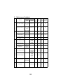
4-3.
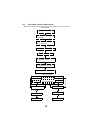
Operation Timing
• A specific function of image stabilization control is carried out as required according to
the situation.
Operating Timing
Processing
• When a new Image Transfer Belt
is detected
• When a new Drum Cartridge or
Toner Cartridge is detected
• When the environment changes
• When 1,000 printed pages have
been produced*1
A
• Ds correction control -> LED intensity
adjustment control -> Belt surface reflection factor measurement control -> Solid
image toner amount control -> Laser
intensity adjustment control -> γ correction control
• When 200 printed pages have
been produced*2
B
• Solid image toner amount control ->
Laser intensity adjustment control -> γ
correction control
• When the processing is commanded from the Control Panel
C
•
γ correction control
✽ 1: When 1,000 printed pages have been produced after A has been performed last.
✽ 2: When 200 printed pages have been produced after A and B have been performed last.
46
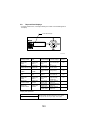
4-4.
Temperature/Humidity Sensor
• The bias voltage is determined based on the value calculated through ATVC (Auto
Transfer Voltage Control) and by the Temperature/Humidity Sensor (environment).
Temperature/Humidity
Sensor (HS1)
4131M038AA
Temperature Data
ATVC Control
Humidity Data
Master Board (PWB-A)
4131m029AA
High Voltage Unit (HV)
Second Image Transfer Bias
47
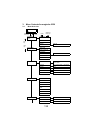
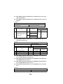
4-5.
ATVC (Auto Transfer Voltage Control
• Adjusts the transfer bias voltage based on the age and cleanliness of the transfer rollers.
ATVC Control
Image Transfer Belt is cleaned
Fixed current is output to first
transfer roller
Resistance of first transfer
roller is measured
First transfer voltage is determined
Second transfer roller is cleaned
Fixed current is output to
second transfer roller
Resistance of second
transfer roller is measured
Second transfer voltage is determined
High Voltage Unit
Fixed Voltage Output
Fixed Current
Fixed Current
Measured Resistance
First Transfer Roller
Second Transfer Roller
Transfer Belt
Transfer Belt
Drive Roller
PC Drum Ground
48
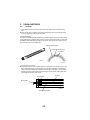
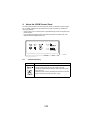
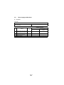
5.
5-1.
DRUM CARTRIDGE
PC Drum
• The photoconductive drum used in this printer is the organic photo conductor (OPC)
type.
✽ This is the PC Drum consisting of the Charge Generating Layer and the Charge Transport Layer applied to an aluminum alloy base.
Handling Precaution
The PC Drum exhibits light fatigue after being exposed to light for a long time, which results
in its sensitivity being changed. Always wrap the drum in the PC Drum Cloth or a soft cloth
immediately after it has been removed from the printer. Use utmost care to protect the surface of the PC Drum from contamination.
Charge Transport Layer
Charge Generating Layer
Aluminum
1167M007AA
1139M007AA
• Grounding of the PC Drum
✽ The PC Drum ground point is located inside, and in the rear of, the PC Drum. It is in constant contact with the Drum Holding Shaft. When the Drum Cartridge is installed in the
printer, the Drum Holding Shaft contacts the ground plate in the printer. This provides for
assured grounding of the PC Drum through the ground point, Drum Holding Shaft, and
ground plate to the frame of the printer.
Ground Plate
PC Drum
Ground Plate
4131M044AA
Drum Holding Shaft
49
5-2.
PC Drum Charging
• The PC Drum Charge Corona employs a comb electrode Scorotron charger system.
• It generates corona emission to deposit a charge evenly across the surface of the PC
Drum through a grid mesh.
• The comb electrode ensures that a charge is concentrated on the grid mesh, thus reducing the amount of ozone produced.
Comb Electrode Charger
PC Drum
Grid Mesh
4131M004AA
Drum Charge Corona Bias
Charge Bias
4131M045AA
50
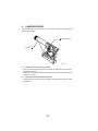
6.
LASER EXPOSURE
An electrostatic latent image is formed on the surface of the PC Drum by a laser light emitted from the print head.
Polygon Motor (M3)
PC Drum
4131M005AB
(1)
FD Direction (vertical scanning direction)
• The Polygon Motor and Main Motor are energized by the PRINT signal, which starts a
paper take-up sequence.
• The printing action in the FD direction is started when the Image Transfer Belt Positioning Sensor is activated.
(2)
CD Direction (horizontal scanning direction)
• The printing action in the CD direction is started by the SOS signal sent from the Laser
Control Board.
51
(3)
Print Area
• The figure below shows the print area in the FD and CD direction.
/HSYNC
/VIDEO
Void Image Width: 4 mm
/VIDEO /TOD
CD Direction: 208 mm
80 ms
Void Image Width: 4 mm
FD Direction: 345 mm
4131M046AA
52
7.
(1)
DEVELOPING UNIT
Toner Cartridge Rack
When printing in each of the four different colors of toner, the Toner Cartridge Rack is
rotated to bring the Toner Cartridge of the corresponding color of toner (K, Y, M, or C) to the
developing position.
(2) Drive for the Toner Cartridge Rack
• The Toner Cartridge Rack is driven by the Rack Motor (M2) and Rack Clutch.
Toner Cartridge
Toner Cartridge Rack
PC Drum
Developing
Roller
Direction of
Rotation
4131M047AA
Developing Roller
Drive Gears
4131M048AA
53
(3)
Drive for the Developing Roller
• The Developing Roller is driven by the Rack Motor (M2) and the Developing Roller Drive
Gears.
• When the Toner Cartridge Rack is stopped at the developing position, the Developing
Roller is rotated by a drive from the Rack Motor (M2) transmitted with the Developing
Roller Drive Gears.
Rack Motor (M2)
Developing Roller
Rack Clutch (CL1)
4131M022AA
54
7-1.
(1)
Developing Position
Toner Cartridge Rack Stop Position for Development
• The stop position for development of each Toner Cartridge is determined by the Rack
Lock Lever and the Rack Home Position Sensor (PC4).
• The Toner Cartridge Rack rotates and the Rack Lock Lever drops into a stopping cutout.
This unblocks the Rack Home Position Sensor (PC4), thus determining the stop position
for the Toner Cartridge for the current use.
(2) Toner Cartridge Rack Standby Position
• The standby position (reference position) of the Toner Cartridge Rack is 20° ahead of the
developing stop position of the black Toner Cartridge.
• When the Toner Cartridge Rack rotates and the Rack Lock Lever moves past the black
position detection cutout (PC4: blocked -> unblocked), the rotating speed of the rack is
decelerated.
Rack Home Position Sensor (PC4)
Rack Lock Lever
Rack Home Position Sensor (PC4)
Yellow Stopping Cutout
Rack Lock Lever
PC Drum
Black Stopping Cutout
Magenta Stopping
Cutout
Black Position
Detection Cutout
4131M049AA
Cyan Stopping Cutout
55
7-2.
(1)
Toner Cartridge
Construction
• The Toner Cartridge is constructed as illustrated below.
4
5
1
4131M050AA
2
1.
2.
3.
4.
5.
4131M051AA
6
3
Toper Hopper
Toner Agitating Plate
Toner Transport Roller
Developing Roller
PC Drum
7
8
6. First Regulator Blade
7. Second Regulator Blade
8. Bias Seal
56
(2)
First Regulator Blade / Second Regulator Blade
• Regulates the amount of toner supplied to the Developing Roller.
(3) Developing Roller
• Carries toner, whose amount has been regulated by the Regulator Blades.
(4) Developing Bias
• Applied to the Developing Roller to ensure that an adequate amount of toner is fed to the
PC Drum.
(5) Toner Empty Detection
• Toner consumption is calculated from image data for toner empty detection.
• When a toner-empty condition is detected, the corresponding message is displayed on
the control panel.
(6) Bias Seal
• Recovers toner that has not stuck to the PC Drum.
2
1
6
7
7
6
5
4131m010
4131M007AA
3
4
1
5
8
3
4
4131M008AA
1.
2.
3.
4.
5.
Developing Roller
PC Drum
First Regulator Blade
Second Regulator Blade
Regulator Blade Bias
6. Developing Bias
7. Developing Seal Bias
8. Bias Seal
57
(7)
Toner Cartridge Installation Detection
• Toner Cartridge installation detection is made with the Toner Cartridge Detection Sensor
(PC8) and the Reflector in the Toner Cartridge.
Detection
Method
Intensity of
Light Reflected
No Cartridge installed
NO
Cartridge installed
YES
Reflector
Reflector
VCC
CPU
GND
PC8
4131M039AA
58
4131M040AA
(8)
Detection of a brand new Toner Cartridge
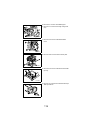
1. A brand new Toner Cartridge is installed.
2. The Front Door is closed. Then, the Power Switch is turned ON.
3. The Toner Cartridge Rack is rotated to bring the Toner Cartridge at the developing position.
4. The Toner Cartridge Detection Sensor (PC8) detects whether or not the Toner
Cartridge is installed.
5. The Toner Cartridge Detection Sensor judges that no Toner Cartridge is installed,
since no light reflection is made with the Reflector placed under the Cover in the
brand new Toner Cartridge.
6. The toner Cartridge, which is detected as “not installed,” is stopped at the
developing position. Then, the Developing Roller is rotated.
7. The Reflector placed under the Cover is pushed out in the Toner Cartridge with a
rotation of the Developing Roller. The Toner Cartridge Detection Sensor detects that
the Toner Cartridge is installed with the light reflection from the Reflector.
8. Other Toner Cartridges are stopped at the developing position respectively. If
the Cartridge is a brand new, sequences from 4 through 7 are repeated for each
Color Toner Cartridge.
According to the above-mentioned sequential operation, the Toner Cartridge is
detected as a brand new one.
No Toner Cartridge Installed
Toner Cartridge Installed
Reflector
4131M042AA
4131M041AA
59
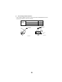
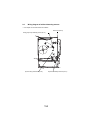
8.
8-1.
(1)
IMAGE TRANSFER
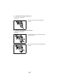
Image Transfer Belt Unit
Construction
1
2
4131M053AA
3
1.
2.
3.
4.
(2)
4
5
6
5. Drive Roller
6. Second Image Transfer Roller
Image Transfer Belt
Cleaning Blade
Waste Toner Conveying Coil
First Image Transfer Roller
Drive Train
1
2
4131M009AA
1. Main Motor (M1)
2. Drive Roller
60
(3)
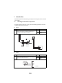
First Image Transfer
• The first image transfer bias is applied to the First Image Transfer Roller to transfer the
toner image on the surface of the PC Drum onto the Image Transfer Belt.
First Image Transfer Roller
Image Transfer Belt
First Image Transfer Bias
4131M054AA
PC Drum
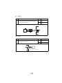
(4)
Second Image Transfer
• The second image transfer bias is applied to the Second Image Transfer Roller to transfer the toner image on the Image Transfer Belt onto the paper.
• The residual charge left on the paper is neutralized by the Charge Neutralizer.
Charge Neutralizing Bias
(Self Bias)
Drive Roller
Charge Neutralizer
4131M055AA
Second Image Transfer Roller
Second Image Transfer Bias
61
(5)
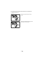
Second Image Transfer Roller Pressure/Retraction
• The Second Image Transfer Roller is pressed against, and retracted from, the Image
Transfer Belt by a cam on the printer side that is turned as the Second Image Transfer
Roller Pressure Contact Solenoid (SL5) is energized or de energized.
• When the Second Image Transfer Roller Pressure Contact Solenoid (SL5) is energized,
the cam on the printer side turns, causing the Pressure Lever to move the Second Image
Transfer Roller away from the Image Transfer Belt.
• The pressure and retracted positions are detected by the Second Image Transfer Roller
Pressure Positioning Sensor (PC7).
Second Image Transfer Roller
Pressure Contact Solenoid (SL5)
Second Image Transfer Roller
4131M010AA
Drive Roller
Second Image
Transfer Roller
Spring
Pressure Lever
Second Image Transfer Roller
Pressure Positioning Sensor
Cam
When Retracted
4131M056AA
When Pressed
4131M057AA
(6)
Second Image Transfer Roller Pressure/Retraction Timing
Pressed
Retracted
Before the paper reaches the Second Image Transfer Roller
After the trailing edge of the paper has moved past the Second Image Transfer
Roller
62
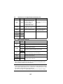
8-2.
Second Image Transfer Roller Cleaning
• A reverse bias is applied to the Second Image Transfer Roller to remove any residual
toner left on the roller.
• The residual toner is transferred onto the Image Transfer Belt and then recovered by the
Cleaning Blade.
(1) Operating Timing
• After the lapse of a given period of time during pre-drive.
• After the paper moves past the Second Image Transfer Roller when a media error
occurs.
• Before the second image transfer ATVC.
4131M037AA
63
8-3.
(1)
Image Transfer Belt Cleaning Mechanism
Image Transfer Belt Cleaning Blade
• The Cleaning Blade is used to scrape any residual toner off the surface of the Image
Transfer Belt.
Image Transfer Belt
Positioning Sensor (PC5)
Cam
Belt Cleaner Separation Solenoid (SL4)
4131M011AA
Cleaning Blade
Opposing Roller
Cleaning Blade
4131M058AA
64
(2)
Image Transfer Belt Cleaning Blade Retraction
• The Image Transfer Belt Cleaning Blade is retracted from the Opposing Roller by a cam
on the printer side that turns as the Belt Cleaner Separation Solenoid (SL4) is energized
or deenergized.
• The cam on the printer side is made into direct contact with the Cleaning Blade housing
so that the Cleaning Blade is retracted.
• The Image Transfer Belt Cleaning Blade is detected at its retracted position when the
cam turns to deactivate the Belt Cleaner Positioning Sensor (PC9).
4131M059AA
Main Motor (M1)
ON
OFF
Belt Cleaner Positioning Sensor
Pressure
Pressure
Belt Cleaner Separation Solenoid (SL4)
Retraction
ON
OFF
* In color printing
65
4131M030AA
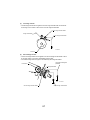
8-4.
Waste Toner Bottle
• Waste toner on the PC Drum and the Image Transfer Belt is collected.
• The waste toner sticking to the surface of the PC Drum is scraped off by the Cleaning
Blade and conveyed by the Waste Toner Conveying Coil.
• The waste toner left on the surface of the Image Transfer Belt is scraped off by the Image
Transfer Belt Cleaning Blade and conveyed by the Waste Toner Conveying Coil.
Cleaning Blade
4131M012AA
8-5.
(1)
Waste Toner Conveying Coil
4131M013AA
Waste Toner Bottle
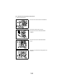
Waste Toner Bottle Detection
Waste Toner Bottle Detection
• The Waste Toner Bottle Set Switch (S5) detects whether or not the Waste Toner Bottle is
installed in the printer.
(2) Waste Toner Full Detection
The Waste Toner Full Detecting Sensor (PC6) detects that the Waste Toner Bottle is full of
waste toner.
• A waste toner full condition is detected when waste toner in the Waste Toner Bottle
blocks the sensor.
Waste Toner Full
Detecting Sensor (PC6)
Waste Toner Bottle
Set Switch (S5)
4131M014AA
66
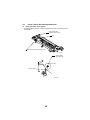
9.
FUSING SECTION
9-1.
(1)
Fusing Unit
Overview
• Toner transferred onto the paper through the image transfer process is permanently fixed
onto the paper.
• The fusing system employed in the printer is a heat roller method, in which the Fusing
Roller heated by a heater lamp is pressed against the Fusing Pressure Roller and, by
feeding the paper between these two rollers, toner is fused onto the paper.
4
3
7
1
2
6
5
4131M015AA
1.
2.
3.
4.
5.
6. Fusing Pressure Roller Heater
Lamp (H2)
7. Pressure Spring
Fusing Roller
Fusing Pressure Roller
Thermistor (TH1))
Thermostat (TS1)
Fusing Roller Heater Lamp (H1)
67
(2)
Drive
• The Fusing Unit is driven by the Main Motor (M1).
Main Motor (M1)
4131M016AA
(3)
Fusing Roller Pressure
• The Fusing Roller and the Fusing Pressure Roller are pressed against each other at all
times. They are released for maintenance service or replacement of parts.
• When a paper misfeed occurs in the Fusing Unit, the Fusing Misfeed Clearing Levers are
pulled upward to release pressure between the two rollers.
Fusing Misfeed Clearing Levers
4131M017AA
68
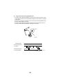
9-2.
(1)
Fusing Temperature Control
Fusing Temperature Control Circuit
• The resistance of the Thermistor (TH) mounted to the Fusing Roller varies with temperature. The higher the temperature, the smaller the resistance value. The output from the
Thermistor (TH) is applied to the analog port of the CPU.
• When the temperature increases and the resistance of the Thermistor (TH) decreases,
the input voltage to the analog port becomes smaller.
• The CPU monitors the output from the Thermistor and turns ON or OFF the Heater Lamp
as necessary to control the temperature of the Fusing Roller.
• To energize the Fusing Roller Heater Lamp (H1), the CPU turns ON (LOW) the Heater
Remote output signal. This turns ON the triac in the Power Unit, which allows an AC voltage to be applied to the Fusing Roller Heater Lamp (H1) to heat it.
• When the temperature of the Fusing Roller runs inordinately high, the Abnormal Heater
Temperature Detecting Circuit is activated to shut down power to the Fusing Roller
Heater Lamp (H1).
PWB-A (Main Board)
CPU
A/D
Main Switch
AC
Input
H1
Abnormal Heater
Temperature
Detecting Circuit
H2
Heater Remote
On/Off
Power Unit
4131M060AA
69
(2)
Fusing Temperature Control
• The temperature control as detailed below is provided by means of the Fusing Roller
Heater Lamp (H1) and the Fusing Pressure Roller Heater Lamp (H2).
• The surface temperature of the Fusing Roller is converted by the Thermistor (TH1) to a
corresponding electrical signal.
1. Warm-up Control
• The temperature during the warm-up cycle is set at 170°.
• When the temperature of the Fusing Roller reaches this set temperature, both the Fusing
Roller Heater Lamp (H1) and the Fusing Pressure Roller Heater Lamp (H2) are turned
OFF.
2. Temperature Control in Standby State
• The temperature in the standby state is set at 171°.
3. Temperature Control during Printing (monochrome printing)
• The temperature during printing is set as follows.
Set temperature
Plain paper
Thick paper
postcards
OHP transparencies
Envelopes
Small size*
157°
157°
157°
166°
152°
✽ Small-size paper: Plain paper whose length is 226 mm or less
4. Temperature Control during Printing (color printing)
• The temperature during printing is set as follows.
Set temperature
Plain paper
Thick paper
postcards
OHP transparencies
Envelopes
Small size*
174°
174°
166°
166°
169°
✽ Small-size paper: Plain paper whose length is 226 mm or less
180
In Standby
During Printing
Plain paper (color)
170
160
Plain paper (monochrome)
Warm-up: approx.
180 sec.
4131M061AA
70
10. PAPER TAKE-UP SECTION
10-1.
(1)
Manual Feed Tray
Paper Take-Up Mechanism
• The Manual Feed Tray consists of a Paper Take-Up Roll, Paper Lifting Plate, and the
Manual Feed Paper Take-Up Solenoid (SL1).
• When the Manual Feed Paper Take-Up Solenoid (SL1) is energized, the cam turns.
At the same time, the Paper Lifting Plate raises the tray and the paper on the tray is
taken up by the Paper Take-Up Roll and fed into the printer.
(2) Paper Empty Detection
• There is the Manual Feed Paper Empty Sensor (PC1) provided on the underside of the
Manual Feed Tray. It detects a paper-empty condition of the Manual Feed Tray.
• When there is paper, the actuator is lowered to unblock the sensor.
• When there is no paper, the actuator is raised to block the sensor.
Manual Feed Paper Take-Up Solenoid (SL1)
4131M019AA
Manual Feed Paper Empty Sensor (PC1)
Main Motor
ON
OFF
Image Transfer Belt
Positioning Sensor
Y
Manual Feed Paper
Take-Up Solenoid
(SL1)
M
C
K
ON
OFF
4131m031AA
* In color printing
71
10-2.
(1)
Lower Feeder Unit (Option)
Paper Take-Up Mechanism
• Since there is no drive motor installed, the drive for paper take-up and transport (supplied
from M1) is transmitted through a drive coupling gear from the printer.
• The same paper take-up mechanism is employed as that of the Multi-Purpose Tray,
except that paper separator fingers are used, instead of the separator roll with a torque
limiter, for paper separation.
• The Lower Feeder Take-Up Solenoid (SL7) is controlled from the printer through the
Lower Feeder Control Board (PWB-A) of the Lower Feeder Unit.
(2) Paper Empty Detection
• A paper-empty condition is detected by the Lower Feeder Paper Empty Sensor (PC16).
• When there is paper, the actuator is raised to block the sensor.
• When there is no paper, the actuator is lowered to unblock the sensor.
Lower Feeder Paper
Near-Empty Sensor (PC14)
Lower Feeder Take-Up
Solenoid (SL7)
4131M020AA
Lower Feeder Paper Empty Sensor (PC16)
(3)
Lower Feeder Paper Near-Empty Sensor (PC14)
• A paper near-empty condition is detected by the Lower Feeder Paper Near-Empty Sensor.
• A paper near-empty condition is equivalent to the following number of sheets of paper left
in the tray.
Specifications
Near-empty detection
50 +/- 25 sheets
72
11. OTHER MECHANISMS
11-1.
(1)
Duplex Unit (Option)
Drive
• The drive for the Duplex Unit works as follows. The paper having a printed image on its
one side is temporarily fed toward the Exit Tray and, as soon as the trailing edge of the
paper moves past the guide plate before the Exit Roller, the Exit Roller is turned backward so that the paper is fed into the Duplex Unit.
• The drive for the Exit Roller is disconnected from the printer when the Duplex Unit is
mounted on the printer and, instead, it is provided by the Duplex Unit Turnover Motor of
the Duplex Unit.
• The Transport Rollers of the Duplex Unit are driven by the Duplex Unit Transport Motor.
• The paper is transported to the printer by the Transport Rollers.
Duplex Unit Turnover Motor (M8)
Duplex Unit Transport Motor (M7)
Transport Rollers
Duplex Unit Transport Sensor (PC17)
4131M021AA
73
(2)
Paper Feeding Method
1. Operations in 2-sided printing with a single sheet of paper resident in, and circulated
through, the system
(1)
Paper is taken up and fed in and the image on
page 2 of the print job is printed.
2
4657M521AA
(2)
The paper is temporarily fed toward the exit
section and, immediately before the paper
2
leaves the Exit Roller, the direction of rotation
of the Exit Roller is switched.
(3)
The paper is transported into the Duplex Unit.
(4)
The paper in the Duplex Unit is temporarily
4657M522AA
stopped at the Duplex paper take-up position.
2
4657M523AA
74
(5)
The image on page 1 of the print job is printed
on the paper that is taken up from the Duplex
Unit.
1
2
(6)
The first paper is fed out of the printer.
4657M524AA
✽ Steps from (2) to (6) are hereafter repeated.
75
2. Operations in 2-sided printing with two sheets of paper resident in, and circulated
through, the system:
(1)
The first sheet of paper is taken up and fed in
and the image on page 2 of the print job is
printed.
2
4657M515AA
(2)
The first sheet of paper is temporarily fed
toward the exit section and, immediately before
the paper leaves the Exit Roller, the direction of
2
rotation of the Exit Roller is switched.
(3)
The first sheet of paper is transported into the
Duplex Unit.
(4)
At the same time, the second sheet of paper is
taken up and fed in.
4657M516AA
(5)
The first sheet of paper in the Duplex Unit is
temporarily stopped at the Duplex paper take-
4
up position.
(6)
2
The image on page 4 of the print job is printed
on the second sheet of paper.
4657M517AA
(7)
The first sheet of paper is taken up from the
Duplex Unit.
4
(8)
The second sheet of paper is temporarily fed
toward the Exit Tray and, immediately before
the paper leaves the Exit Roller, the direction of
2
rotation of the Exit Roller is switched.
4657M518AA
76
(9)
The image on page 1 of the print job is printed
on the first sheet of paper.
4
(10) The second sheet of paper is transported into
the Duplex Unit.
1
2
4657M519AA
(11) At the same time that the first sheet of paper is
fed out of the printer, the image on page 3 is
2
printed on the second sheet of paper.
1
3
4
4657M526AA
(12) At the same time that the second sheet of
2
4
paper is fed out of the printer, the third sheet of
3
paper is taken up and fed in and the image on
page 6 is printed on the third sheet of paper.
1
3
4657M527AA
✽ Steps from (2) to (12) are hereafter repeated.
77
3. Operations in 2-sided printing with two sheets of paper resident in the system and with
a new sheet of paper taken up when a printed page with images printed on both sides is
fed out
(1)
The first sheet of paper is taken up and fed in
and the image on page 2 of the print job is
2
printed.
(2)
The first sheet of paper is temporarily fed
toward the exit section and, immediately before
4
the paper leaves the Exit Roller, the direction of
rotation of the Exit Roller is switched.
(3)
(4)
The first of paper is fed in the duplex unit.
At the same time that the second sheet of
paper is taken up and page4 is printed.
4657M528AA
(5)
The first sheet of paper is stopped at take-up
(6)
The second sheet of paper is fed in exit sec-
position.
4
tion.
2
4657M529AA
4
(7)
The image on page 1 of the print job is printed
(8)
The second sheet of paper is immediately
on the first sheet of paper.
before the paper leaves the Exit Roller, the
direction of rotation of the Exit Roller is
switched.
1
(9)
2
The second sheet of paper fed in the duplex
unit.
4657M530AA
78
(10) The first sheet of paper fed out in exit tray.
2
(11) At the same time the third sheet of paper is
1
taken up and fed in.
(12) The second of sheet of paper stopped at takeup position.
4
6
4657M531AA
(13) The image on page 3 is printed on the second
sheet of paper.
6
2
(14) The third sheet of paper is immediately before
1
the paper leaves the Exit Roller the direction of
rotation of the Exit Roller is switched.
(15) The third sheet of paper fed in the Duplex Unit.
3
4
4657M532AA
(16) The second sheet of paper fed out in Exit Tray.
(17) At the same time the fourth sheet of paper is
4
2
taken up and fed in.
3
(18) The third sheet of paper stopped at take-up
position.
1
8
6
4657M532AA
✽ Steps from (13) to (18) are hereafter repeated.
79
80
MAINTENANCE & DISASSEMBLY/ASSEMBLY
81
19971
1.
1-1.
Disassembly/Assembly Precautions
Precautions for disassembly and assembly
• Unplug the power cord from the electrical outlet before servicing the printer.
• Reassemble the unit in reverse order of disassembly unless otherwise instructed.
• If it is necessary to run the printer with its covers removed, use extreme care to avoid
catching your fingers or clothing in rotating parts such as gears, rollers, or motors.
• Never touch the terminals of electrical components or high-voltage components, such as
the power unit or the high-voltage unit.
• Be careful when working around the fusing unit because it will be hot long after the
printer is turned off. Wait until the fuser has cooled before disassembly.
• Turn off the printer before plugging or unplugging a power cord. Never plug or unplug a
power cord that is energized. When plugging or unplugging connectors, be sure to hold
the plug. Never pull on the cord or you may break the wires connecting the plug to the
power cord.
• Use only fuses of the specified rating.
• To ensure electrical conduction, attach the ground wire. In addition, be sure to use the
screws with toothed washers as instructed.
1-2.
Parts that must not be touched
Do not remove, disassemble, or adjust any of the parts listed below:
• Print head unit (disassembly or adjustment)
• Components with mounting screws that are painted red.
1-3.
Precautions for transporting or storing PWBs
Observe the following precautions when handling circuit boards.
• During transportation or storage, circuit boards must be placed in anti-static bags and
must not be unnecessarily removed. Do not wrap the circuit boards in plastic or paper
bags.
• Do not store or place circuit boards in a location exposed to direct sunlight.
• When it becomes necessary to remove a circuit board from the anti-static bag, do not
place it where it is easily be affected to static electricity, such as on carpet, plastic, or in
vinyl bags.
1-4.
Precautions for replacing PWBs
• Generally, the PWB or the assembly should be replaced.
• When unplugging connectors from the circuit board, ensure the power is off.
• When removing a circuit board from its anti-static bag, or when replacing the circuit
board, hold the board by its edges, making sure not to touch pins of the ICs or the printed
pattern.
1-5.
Precautions for inspecting PWBs
• Do not check ICs directly with a multimeter; use connectors on the circuit board.
• Never create a closed circuit across IC pins with a metal tool.
• When it is necessary to touch ICs and other electrical components on the circuit board,
be sure to first ground yourself.
83
1-6.
Precautions for transporting or storing the OPC drum cartridge
• Use the specified carton when transporting or storing the OPC drum (magicolor 2350)/
PC drum (magicolor 2300 dl).
• Do not store or place an OPC drum cartridge in a location where it will be exposed to
direct sunlight. The storage temperature should be between -4°F(-20°C) to 104°F
(+40°C).
1-7.
Precautions for handling the OPC drum cartridge
• The OPC drum cartridge is extremely sensitive to light shock. It takes a long time to
recover the drum’s photosensitivity. Never leave the protective cover open or expose the
OPC drum cartridge to direct sunlight for long periods of time.
• Do not contaminate the surface of the OPC drum cartridge with fingerprints, oil or chemicals.
• Do not scratch the surface of the OPC drum cartridge.
1-8.
Red painted Screws
Purpose of Application of Red Paint
Red painted screws show that the assembly or unit secured can only be adjusted or set at
the factory and should not be adjusted, set, or removed in the field.
Note that when two or more screws are used on the part in questions, only one representative screw may be marked with red paint.
1-9.
Variable Resistors on Board
Do not turn the variable resistors on boards for which no adjusting instructions are given.
84
2.
Maintenance Schedule
Maintenance Cycle
Fusing Section PH Section
Developing Section
Image Transfer Section
éþ
Transfer Section
Paper Take-Up Section
PM Parts
Near
Life
Detection
Ref. Page
Life
Print
in This
DetecInhibited
Manual
tion
Clean
Replace
Paper Take-Up Roller
When paper
take-up failure
occurs
200K Prints
NO
NO
NO
89
Separator Roller Assy
When paper
take-up failure
occurs
200K Prints
NO
NO
NO
89
Paper Dust Roller
When paper
transport failure occurs
-
NO
NO
NO
90
Transport Roller
When paper
transport failure occurs
-
NO
NO
NO
91
2nd Image Transfer
Roller
-
120K Prints
NO
NO
NO
92
Image Transfer Belt Unit
-
210K Prints
B&W
52.5K Prints
Color
NO
NO
NO
94
Waste Toner Bottle
-
25K Images
YES
YES
YES
91
Around waste toner
collecting port
When the
Waste Toner
Bottle is
removed
-
NO
NO
NO
91
Toner Cartridge C/M/Y/K
-
4.5K Prints
(High Cap)
1.5K Prints
(Standard)
YES
YES
NO
94
OPC Drum Cartridge
-
45K Images B&W
11.25K
Images Color
YES
YES
NO
93
Laser Lens Cover
When an
image problem occurs
-
NO
NO
NO
92
Fusing Unit
-
120K Prints
NO
NO
NO
95
85
NOTES
✽ Replace the Paper Take-Up Roll and Separator Roll at the same time.
✽ Replace the Second Image Transfer Roller and Fusing Unit at the same time.
✽ When the Fusing Unit has been replaced, reset the counter on the control panel. (See CONTROL
PANEL/SERVICE MODE DESCRIPTIONS.)
✽ When the Image Transfer Belt Unit and Second Image Transfer Roller have been replaced, reset the
counter on the control panel. (See CONTROL PANEL/SERVICE MODE DESCRIPTIONS.)
Every one color developed in one count up.
86
2-1.
Guideline for Life Specifications Values by Unit
Life Value
Near Life Value
Life Value
TC with machine (1.5K pages)
Toner Cartridge
4.5K Pages
(C/W)
• When reach the TC consumption ratio in 89%.
After TV (4.5K pages)
When reach the TC consumption
ratio in 100%.
• When reach the TC consumption ratio in 96%.
OPC Drum
Cartridge
45K
images
Waste Toner
Bottle
25K
images
Image Transfer Belt Unit
210K
images
Fusing Unit
120K
Pages
2nd Image
Transfer Roller
120K
Pages
2-2.
When reach the DC consumption ratio in 96%.
When reach the DC consumption
ratio in 100%.
When detect near life information
from Main unit.(Master Board)
Print out the 200 images (monochrome) or 50 images(color),
after detect the near life.
-
-
Detail of Each Unit Life
Kind of
Paper
Toner Cartridge
OPC Drum
Cartridge
Waste Toner
Bottle
Detail of Life
Plain Paper
C/W ratio 5% less: 1.5K images - 4.5K images *1
Special
Paper
C/W ratio 5% less: 1.0K images - 4.5K images *1
Plain Paper
Special
Paper
Plain Paper
Special
Paper
Waste Toner
Bottle
Plain Paper
Fusing Unit
Plain Paper
2nd Image
Transfer Roller
Plain Paper
Standard Life Specification Value: monochrome 13.5K prints, color
4.5K prints (TOTAL 18K prints)
Continuous: monochrome 15K prints, color 7.5K print
C/W ratio 5% Prints, Waste toner capacity:
monochrome 25K images, color 6.25K images *1
Standard Life Specification Value: monochrome 60K prints, color
20K prints (TOTAL 80K prints)
Standard Life Specification Value: monochrome 90K prints, color
30K prints (TOTAL 120K prints)
✽ 1: The Life Specification Value represents the number of prints made or figures equivalent to it when given conditions are met. They can be more or less depending on the
printer operating conditions of each individual user.
NOTES
• The Life Value represents the number of printed pages or a figure equivalent to it when
given conditions (shown below) are met. It can be more or less depending on the operating conditions of the machine of each individual user.
• One color is one image. One printed page produced in color is counted four images.
87
Conditions for Life Specifications Values
magicolor 2300DL, 2350, 2300W
Print conditions
Monochrome: producing three printed pages continuously; color:
making two printed pages continuously
Paper Size
A4C or Letter C
Color Ratio
Monochrome : Color = 3 : 1
Density
C/W(Coverage/White) ratio = 5% in each color
88
3.
(1)
Maintenance And Cleaning
Cleaning of the Paper Take-Up Roller
1. Open the right-side door.
2. Using a soft cloth dampened with alcohol, wipe
the Paper Take-Up Roll clean of dirt.
C4131o073AB
(2)
Replacement the Paper Take-up Roller
1. Remove the right-side door.
2. Remove the knob, and then replace the Paper
Take-up Roll.
4131D058AB
3. Cleaning of the Paper Separator Roll
4. Remove the right-side door.
5. Remove two screws and the Paper Separator
Roll Mounting Assy.
4131D058AC
6. Using a soft cloth dampened with alcohol, wipe
the Paper Separator Roll clean of dirt.
4658D006AA
89
(3)
Replacement of the Paper Separating Roller Assy
1. Remove the right-side door.
2. Remove two screws and the Paper Separator
Roll Mounting Assy.
4131D058AC
3. Take off the rubber stopper, shaft, spring, and
guide plate to remove the Paper Separator Roll
fixing bracket assy.
4658D003AA
4. Snap off one E-ring and the Paper Separator Roll
Assy.
5. Remove the Paper Separator Roll.
6. To reinstall, reverse the order of removal.
4658D004AA
(4)
Cleaning of the Paper Dust Roller
1. Remove the Transport Unit.
2. Using a soft cloth dampened with alcohol, wipe
the Paper Dust Roller Roll clean of dirt.
4131D510AA
90
(5)
Cleaning of the Transport Roller
1. Open the Right-side Door.
2. Using a soft cloth dampened with alcohol, wipe
the Transport Roller clean of dirt.
C4131o073AC
(6)
Replacement of the Waste Tonner Bottle
1. Open the Front Door.
2. Hold onto the handle of the Waste Toner Bottle
and, while slightly pulling the bottle to the front,
pull it upward.
C4131o049AA
3. Mount the cap to the waste toner collecting port.
NOTE
Discard the Waste Toner Bottle according to the
applicable local regulation.
4. To reinstall, reverse the order of removal.
C4131o041AA
(7)
Cleaning of the Areas around Waste Toner Collections Port
1. Open the Front Door.
2. Remove the Waste Toner Bottle.
3. Wipe the areas around the waste toner collecting
port clean of dirt using a soft cloth dampened with
alcohol.
C4131o040AA
91
(8)
Cleaning of the Laser Lens Cover
1.
2.
3.
4.
Open the Front Door.
Remove the Waste Toner Bottle.
Withdraw the Laser Lens Cover.
Wipe the lens of the Laser Lens Cover clean of
dirt using a soft cloth dampened with alcohol.
C4131o043AA
(9)
Replacement of the Second Image Transfer Roller
4131D004AA
1. Remove the Right-side Door.
2. While pulling the bushings (white) at the front and
rear ends of the 2nd Image Transfer Roller to the
rear and to the front, respectively, place them
down to the right. Then, remove the 2nd Image
Transfer Roller from the 2nd Image Transfer
Roller Holder.
3. To reinstall, reverse the order of removal.
4. Select functions as follows: Engine/Service ->
Power On Test. Then, execute ATVC.
92
4.
Replacement of the Units
(1)
Replacement of the OPC Drum Cartridge
1. Open the Front Door.
2. Remove the Waste Toner Bottle.
3. Lower the unlock lever and remove the Drum
Cartridge.
C4131o027AA
4. Reinstall the new Drum Cartridge.
C4131o030AA
5. Pull the protective sheet of the Drum Cartridge to
the front and remove it.
6. Raise the unlock lever.
C4131o031AA
93
(2)
Replacement of the Image Transfer Belt Unit
1.
2.
3.
4.
Open the Front Door.
Remove the Waste Tonner Bottle.
Remove the Drum Cartridge.
Remove two screws and the Image Transfer Belt
Unit.
NOTE
When replacing the Image Transfer Belt Unit, be sure
to remove the packing materials.
Do not touch the transfer belt with bare hands.
5. To reinstall the belt unit, reverse the order of
removal.
6. Select functions as follows: Service -> Service/
Service Person -> Reset Counter/Fuser Unit.
Then, clear the counter.
4131D061AA
(3)
Replacement of the Toner Cartridge
1. Open the Front Door.
2. Remove the Waste Tonner Bottle.
3. Remove the Drum Cartridge.
NOTE
Discard the Toner Cartridge according to the applicable local regulation. Do not throw the Toner Cartridge into an open flame.
C4131o018AA
4. Remove the packing materials and install the
Toner Cartridge.
5. Enter the capacity of the Toner Cartridge just
installed through the control panel.
E.g.: If a Yellow Toner Cartridge has been
replaced (4.5 K)
“Menu/Engine -> Replace Toner -> Yellow ->
High”
C4131o021AA
94
(4)
Replacement of the Fusing Unit
1. Remove the Top Front Cover.
2. Remove the Top Cover.
3. Open the Right-side Door.
4. Remove two screws and the Fusing Unit Cover.
4131D032AA
4131D033AA
5. Unplug the connector from the Power Unit and
remove the harness from the cord holder.
6. Remove the Fusing Unit from the machine (two
screws and two connectors).
7. To reinstall the Fusing Unit, reverse the order of
removal.
8. Select functions as follows: Service -> Service/
Service Person -> Reset Counter/Fuser Unit.
Then, clear the counter.
95
4-1.
(1)
Disassembly Procedures
Doors, Covers, And Exterior Parts:
Identification And Removal Procedures
2
6
1
3
4
5
7
8
9
96
No.
Name
Removal Procedure
1
Top Front Cover
Open the Front Door and Right Door. -> Remove two screws and the
Top Front Cover.
2
Top Cover
3
Right-side Rear Cover
Remove the Controller Protective Cover. -> Remove the Rear Cover. > Remove two screws and the Right-side Rear Cover.
4
Right-side Door Cover
Remove two screws and the Right-side Door Cover.
5
Front Door
Open the Right Door. -> Remove the Top Front Cover. -> Remove the
Top Cover. -> Remove the Front Door.
6
Rear Cover
Remove the Controller Board Protective Cover. -> Remove eight
screws and the Rear Cover.
7
Controller Board Protective Cover
8
Left-side Cover
Open the Right Door. -> Remove the Top Front Cover. -> Remove the
Top Cover. -> Remove three screws and the Left-side Cover.
9
Front Cover
Open the Right Door. -> Remove the Top Front Cover. -> Remove the
Top Cover. -> Remove the Front Door. -> Remove nine screws and the
Front Cover.
Open the Front Door and Right Door. -> Remove the Front Upper
Cover. -> Remove five screws and the Top Cover.
Loosen nine screws, remove two screws, and remove the Controller
Board Protective Cover.
97
4-2.
Pre-disassembly preparation
Before disassembling the machine, the following units need to be removed.
• Waste toner bottle
• OPC drum cartridge
• Toner cartridges (4 colors)
• Image transfer belt unit
1. Open the front door.
2. Remove the waste toner bottle.
4131o023AA
3. Remove the OPC drum cartridge.
4131o027AA
4. Remove the image transfer belt unit. (2 screws)
Note
When replacing the image transfer belt unit, be
sure to remove the packing material.
Do not touch the image transfer belt with your
bare hands.
4131D061AA, 4131D062AA
98
5. Remove all toner cartridges.
(1) magicolor 2350 procedures:
a)From the display, select the menu “Quality”.
b)Select “Toner”, then “Replace”
c) Select each toner color of the cartridge to be
removed, and then press the Select key to
move the cartridge to the removal position.
(2) magicolor 2300 DL procedures
a)From the display, select the menu “Engine”.
b)Select “Replace Toner”.
c) Select each color toner cartridge from this
menu to remove it.
(3) magicolor 2300W procedures
a)Open the Status Display from the connected
PC.
b)From the Printer tab choose Toner Replace...
c) Select each color toner and follow the procedures to replace.
4131o017AA
(4)
Manual removal procedures
Caution:
Rotate the carousel carefully to prevent injury to your
fingers.
a)Press in the toner carousel latch and carefully
turn the carousel until the next cartridge is
positioned for removal. Remove the toner cartridge.
b)Repeat step b until all toners have been
removed.
2
1
4131D003AA
4
3
4131D063AA
4131D064AA
1 Toner cartridge
2 OPC drum cartridge
3 Waste toner bottle
4 Image transfer belt unit
99
4-3.
Removal Of Circuit Boards And Other Electrical Components
NOTES
• When removing a circuit board or other electrical component, refer to “Handling of
PWBs” and follow the corresponding removal procedures.
• The removal procedures given in the following omit the removal of connectors and
screws securing the circuit board support or circuit board.
• Where it is absolutely necessary to touch the ICs and other electrical components on the
board, be sure to ground your body.
PWB-P
PWB-A
PU
PWB-A
PWB-A
HV
Symbol
Name
Removal Procedure
PWB-A
Master Board
101
PWB-P
Controller Control
Board
102
PU
Power Unit
102
HV
High Voltage Unit
103
PWB-A
Lower Feeder Control
Board
104
PWB-A
Duplex Unit Control
Board
105
100
(1)
Removal of the Rear Cover
1. Remove the Rear Cover
2. Remove the harness and connector.
3. Remove five screws and the Master Board
(PWB-A).
NOTE
When the Master Board has been replaced, be sure
to demount EEPROM from the old master board and
mount it to the new one.
4131D007AB
(2)
To replace the Master Board
Note
• When replacing the master board, be sure to move the EEPROM from the old master
board to the new one.
1. Remove the rear cover and the master board.
2. Replace the EEPROM (IC3).
(New)
(Old)
4131D056AB
Note
Be sure to install the EEPROM so that it
faces the correct direction.
4131D059AB
101
(3)
Removal of the Controller Board
1. Remove the Controller Board Protective Cover.
2. Remove the harness and connector.
3. Remove seven screws and the Controller Board
(PWB-P).
4131D055AB
(4)
1.
2.
3.
4.
Removal of the Power Unit
Open the Right-side Door.
Remove the Top Front Cover.
Remove the Top Cover.
Remove the Left-side Cover.
5. Remove three screws and the protective cover.
4131D013AA
6. Remove the harness, connector, and PWB support.
7. Remove three screws and the Power Unit.
4131D014AB
102
(5)
Removal of the High Voltage Unit
1.
2.
3.
4.
5.
6.
Open the Right-side Door.
Remove the Top Front Cover.
Remove the Top Cover.
Remove the Rear Cover.
Remove the Left-side Cover.
Remove the Controller Protective Cover.
7. Remove the harness and connector.
8. Remove seven screws and the Controller Board
(PWB-P).
4131D055AB
9. Remove seven screws and the Controller Box.
4131D016AA
10. Remove the connector and PWB support.
11. Remove four screws and the High Voltage Unit
(HV).
4131D017AA
103
(6)
Removal of the Lower Feeder Control Board
1. Remove three screws and the Lower Feeder
Control Board Assy.
4131D072AA
2. Remove the harness and connector.
3. Remove one screw and the PWB protective
cover.
4131D073AA
4. Remove two screws and the Lower Feeder Control Board.
4131D074AA
104
(7)
Removal of the Duplex Unit Control Board
1. Remove one screw and the PWB Protective
Cover.
4131D075AA
2. Remove the harness and connector.
3. Remove two screws and the Duplex Unit Control
Board.
4131D076AA
105
4-4.
(1)
1.
2.
3.
4.
5.
Removal of Units
Removal of the Right-side Door
Remove the Front Door.
Remove the Controller Protective Cover.
Remove the Rear Cover.
Remove the Front Cover.
Remove the Right-side Rear Cover.
6. Remove the harness and connector.
7. Slightly open the Right-side Door and, supporting
the door with your hand, remove one screw and
two C-rings.
4131D027AA
8. Pull out the shaft and remove the Right-side
Door.
4131D027AA
(2)
1.
2.
3.
4.
5.
Removal of the Print Head Unit (PH)
Remove the Front Door.
Remove the Controller Protective Cover.
Remove the Rear Cover.
Remove the Front Cover.
Remove the Right-side Cover.
6. Remove the harness and connector.
7. Slightly open the Right-side Door and, supporting
the door with your hand, remove one screw and
two C-rings.
4131D027AA
106
8. Pull out the shaft and remove the Right-side
Door.
4131D028AA
9. Remove the harness and connector.
10. Remove two screws and the Drum Unit Slide
Cover.
4131D037AA
11. Remove one screw and the Laser Lens Cover.
4131D038AA
12. Remove two screws and the Print Head Cover.
4131D038AA
13. Remove three screws and the Print Head Unit
(PH).
4131D040AB
107
(3)
Removal of the Fusing Unit
1. Remove the Top Front Cover.
2. Remove the Top Cover.
3. Open the Right-side Door.
4. Remove two screws and the Paper Exit Assy.
4131D032AA
5. Remove the harness and connector.
6. Remove two screws. Then, remove the Fusing
Unit from the machine.
4131D033AA
(4)
1.
2.
3.
4.
5.
6.
7.
8.
Removal of the Transport Unit
Open the Right-side Door.
Remove the Top Front Cover.
Remove the Top Cover.
Remove the Controller Board Protective Cover.
Remove the Controller Board.
Remove the Rear Cover.
Remove the Front Door.
Remove the Front Cover.
9. Remove the harness and connector.
10. Remove five screws and the Master Board
(PWB-A).
4131D009AA
108
11. Remove seven screws and the Controller Box.
4131D016AA
12. Remove two screws and the Master Board
Cover.
4131D018AA
13. Remove the harness and connector.
14. Remove ten screws and the Transport Unit.
4131D504AA
109
(5)
Removal of the Duplex Unit
1. Open The Right-side Door.
2. Remove two screws.
3. Supporting the Duplex Unit with your hand,
remove the cable hook.
C4131o082AB
(6)
Removal of the Lower Feeder
1. Remove one screw and the rear panel fixing
bracket.
C4131o091AA
2. Open the Front Door and slide out the Second
Paper Cassette.
3. Remove two screws and the two front panel fixing
brackets.
C4131o092AA
110
4-5.
(1)
1.
2.
3.
4.
DISASSEMBLY OF THE ENGINE PARTS
Power Supply Cooling Fan Motor
Open the Right-side Door.
Remove the Top Front Cover.
Remove the Front Cover.
Remove the Rear Cover.
5. Remove the harness and connector.
6. Remove two screws and the Power Supply Cooling Fan Motor.
4131D010AA
(2)
Removal of the Fusing Cooling Fan Motor
1. Remove the Right-side Door.
2. Remove the Right-side Door Cover.
3. Remove one screw and the Right Front Cover.
4131D029AA
4. Remove six screws and the Paper Exit Unit.
4131D030AA
5. Remove the harness and connector.
6. Remove four screws and the Fusing Cooling Fan
Motor.
4131D031AA
111
(3)
1.
2.
3.
4.
Removal of the Ventilation Fan Motor
Open the Right-side Door.
Remove the Top Front Cover.
Remove the Top Cover.
Remove the Rear Cover.
5. Remove the harness and connector.
6. Remove two screws and the Ventilation Fan
Motor.
4131D012AA
(4)
Removal of the Main Motor Assembly
1. Remove the Controller Protective Cover.
2. Remove the Rear Cover.
3. Remove seven screws and the Controller Box.
4131D016AA
4. Remove the harness and connector.
5. Remove five screws and the Master Board
(PWB-A).
4131D009AA
6. Remove two screws and the Master Board
Cover.
4131D018AA
112
7. Remove four screws and the Main Motor Assy.
4131D020AA
(5)
1.
2.
3.
4.
5.
6.
Removal of the Rack Motor
Open the Right-side Door.
Remove the Top Front Cover.
Remove the Top Cover.
Remove the Rear Cover.
Remove the Left-side Cover.
Remove the Controller Protective Cover.
7. Remove seven screws and the Controller Box.
4131D016AA
8. Remove the connector and PWB Support.
9. Remove four screws and the High Voltage Unit
(HV).
4131D017AA
10. Remove one screw and the Belt Cleaner Separation Solenoid.
4131D068AA
113
11. Snap off one E-ring and remove the cam from the
inside of the printer.
12. Remove five screws and the Rack Drive Assy.
4131D069AA
13. Snap off one E-ring. Then, remove the Rack
Clutch Shaft and the Drive Gear.
4131D070AA
14. Remove two screws and the Rack Motor.
4131D071AA
(6)
Removal of the Turnover Motor And The Transport Motor
1. Remove one screw and the Protective Cover.
4131D075AA
2. Remove the harness and connector.
3. Remove two screws and the Duplex Unit Control
Board.
4131D076AA
114
4. Remove the harness and connector.
5. Remove one screw and the Duplex Unit Cover.
4131D048AA
6. Remove two screws and the Duplex Unit Turnover Motor.
7. Remove two screws and the Duplex Unit Transport Motor.
4131D049AA
(7)
1.
2.
3.
4.
5.
6.
Removal of the Manual Feed Take-up Solenoid
Remove the Top Front Cover.
Remove the Top Cover.
Remove the Rear Cover.
Remove the Left-side Cover.
Remove the Right-side Door.
Remove the Front Cover.
7. Remove the harness and connector.
8. Remove five screws and the Master Board
(PWB-A).
4131D009AA
9. Remove seven screws and the Controller Box.
4131D016AA
115
10. Remove the connector and PWB Support.
11. Remove four screws and the High Voltage Unit
(HV).
4131D017AA
12. Remove two screws and the Master Board
Cover.
4131D018AA
13. Remove eleven screws and the bottom plate.
4131D065AA
14. Remove five screws and the Manual Feed TakeUp Assy.
4131D066AA
15. Remove one screw and the Manual Feed Paper
Take-Up Solenoid.
4131D067AA
116
(8)
Removal of the Transport Roller Solenoid
1. Remove the Transport Unit
See page 108
2. Remove one screw and the Transport Roller
Solenoid.
4131D507AA
(9)
Removal of the Synchroning Roller Solenoid
1. Remove the Transport Unit
See page 108
2. Remove two screws and the Transport Unit gear
mounting bracket.
4131D505AA
3. Remove one screw and the Synchronizing Roller
Solenoid.
4131D506AA
117
(10) Removal of the Second Image Transfer Roller Pressure Contact Solenoid
1. Remove the Transport Unit
See page 108
2. Remove the Transport Unit gear mounting
bracket.
4131D505AA
3. Remove one screw and the 2nd Image Transfer
Roller Pressure Contact Solenoid.
4131D509AA
118
(11) Removal of the Belt Cleaner Separation Solenoid
1.
2.
3.
4.
5.
6.
Open the Right-side Door.
Remove the Top Front Cover.
Remove the Top Cover.
Remove the Rear Cover.
Remove the Left-side Cover.
Remove the Controller Protective Cover.
7. Remove the harness and connector.
8. Remove two screws and the Power Supply Cooling Fan Motor.
4131D010AA
9. Remove seven screws and the Controller Box.
4131D016AA
10. Remove the connector and PWB Support.
11. Remove four screws and the High Voltage Unit
(HV).
4131D017AA
12. Remove one screw and the Belt Cleaner Separation Solenoid.
4131D068AA
119
(12) Removal of the Fusing Paper Loop Solenoid
1. Remove the Rear Cover
2. Remove seven screws and the Controller Box.
4131D016AA
3. Remove the harness and connector.
4. Remove five screws and the Master Board
(PWB-A).
4131D009AA
5. Remove two screws and the Master Board
Cover.
4131D018AA
6. Remove one screw and the Fusing Paper Loop
Solenoid.
4131D019AA
120
(13) Removal of the AIDC sensor
1. Remove the Top Front Cover.
2. Remove the Top Cover.
3. Remove the Left-side COver.
4. Remove three screws and the protective cover.
4131D013AA
5. Remove the harness, connector, and PWB Support.
6. Remove three screws and the Power Unit.
4131D014AA
7. Remove the wiring saddle on the protective
sheet.
8. Peel off the protective sheet and remove two
screws and the AIDC Sensor.
NOTE
Do not remove the protective sheet.
4131D015AA
121
(14) Removal of the Manual feed tray
1.
2.
3.
4.
Remove the Top Front Cover.
Remove the Top Cover.
Remove the Front Cover.
Remove the Left-side Cover.
5. Remove two screws and the switch box.
4131D021AA
6. Snap off the C-ring and remove the Manual Feed
Tray.
4131D022AA
(15) Disassembly of the Fusing Unit
1. Remove the Fusing Unit.
See page 108
2. Remove two screws and the cover.
4131D050AB
3. Remove six screws and the Heater Lamp.
Notes for installation
Be sure to install the screws securing the leads in the
correct locations.
4131D051AA
122
4. Remove two screws and the Thermostat (TS1).
4131D053AA
5. Remove the Fusing Roller and Fusing Pressure
Roller (screw, E-ring, C-ring).
4131D054AA
Notes for installation
When installing the fusing roller and the fusing pressure roller, install them with the specified misalignment.
Standard: ±3 mm or less
3 mm or less
3 mm or less
Fusing pressure roller
Fusing roller
123
(16) Disassembly of the toner cartridge rack
1. Remove the controller protective cover, topfront cover, top cover, left-side cover, rear
cover, controller, controller box, high-voltage
unit, master board, and master-board bracket.
2. Remove the rear-rack shaft cover. (3 screws)
rack1
3. Remove the screws securing the rack disk to
the toner-cartridge rack. (4 screws)
rack2
4. Remove the front-rack shaft cover. (2 screws)
rack3
5. Separate the toner-cartridge rack from the
rack disk.
rack3a
124
6. Remove the toner-cartridge rack and rack disk
from the printer.
rack4
125
126
CONTROL PANEL / SERVICE MODE DESCRIPTIONS
127
1.
Control Panel Descriptions—2300DL & 2350
✽ For details, refer to the User’s Guide supplied with the unit.
1-1.
Names of control panel parts and their functions
1
5
4
6
2
C4131o015AA
3
9
No.
1-2.
(1)
8
Name
7
Function/details
1
Green LED indicator
• Lights up to indicate that the
printer is ready to print.
2
Orange LED indicator
• Lights up to indicate that an
error has occurred.
3
Cancel Key
• Press to cancel the print job.
• IDLE is displayed.
4
Prev. Key
5
Up key
6
Next Key
7
Down Key
8
Menu Select Key
• Press to enter the configuration menu or to apply the currently selected setting.
9
Message Window
• Displays the status or configuration of the printer.
• Press to scroll through the
menus.
Message Window
Ready screen
The ready screen is the initial message that appears after the unit is finished warming up
and after a menu setting is cancelled.
MAGICOLOR 2350
IDLE
IDLE
MAGICOLOR 2300DL
C4131o001AA
(2)
Warning screen
129
The following appear in the warning screen according to the condition of the printer.
<Malfunction display>
This generally appears when a malfunction that cannot be corrected by the user has
occurred.
Example: Malfunction that can be indicated with malfunction code.
SERVICE CALL 04
ENGINE BOARD
FATAL ERROR
CODE: 04H
C4131o002AA
<Error display>
This appears when an error has occurred.
Example: There is a media misfeed or a door is open
PAPER JAM
FUSER
MEDIA JAM
FUSER
C4131o003AA
<Caution display>
This appears if printing is possible, but an error in the near future is expected.
Example: The black toner cartridge is empty.
BLACK EMPTY
REPLACE?
TONER EMPTY
BLACK
C4131o004AA
130
(3)
Status Messages
magicolor 2300 DL Messages
magicolor 2350 Messages
CALIBRATING
CALIBRATING
CANCELLING JOB
CANCELLING JOB
ENERGY SAVER
ENERGY SAVER
IDLE MAGICOLOR 2300DL
MAGICOLOR 2350 IDLE
PRINTING
PRINTING
PROCESSING
PROCESSING
WARMING UP
WARMING UP
STARTING SYSTEM
COPYING # of #
INITIALIZING
C TONER LOW
CYAN LOW REPLACE?
M TONER LOW
MAGENTA LOW REPLACE?
K TONER LOW
BLACK LOW REPLACE?
Y TONER LOW
YELLOW LOW REPLACE?
TONER EMPTY BLACK
BLACK EMPTY REPLACE?
TONER EMPTY YELLOW
YELLOW EMPTY REPLACE?
TONER EMPTY CYAN
CYAN EMPTY REPLACE?
TONER EMPTY MAGENTA
MAGENTA EMPTY REPLACE?
MEDIA JAM TRAY 1
PAPER JAM TRAY 1
MEDIA JAM TRAY 2
PAPER JAM TRAY 2
MEDIA JAM DUPLEX LOWER
PAPER JAM DUPLEX
MEDIA JAM DUPLEX UPPER
MEDIA JAM TRANSFER ROLLER
PAPER JAM TRANSFER
MEDIA JAM FUSER
PAPER JAM FUSER
MEDIA JAM EXIT
PAPER JAM EXIT
TRAY 1 EMPTY
TRAY 2 EMPTY
WASTE: NEAR FULL
DRUM CARTRIDGE END OF LIFE
REPLACE OPC DRUM
DRUM LOW
OPC DRUM LOW
PRINTER COVER OPEN
MAIN UNIT COVER OPEN
PUT PAPER:TRAY 2 "SIZE"
PUT MEDIA:TRAY1 "SIZE"
PUT [X] IN [Y]
DRUM CARTRIDGE NOT ATTACHED
OPC DRUM MISSING
WASTE TONER BOX NOT ATTACHED
WASTE TONER MISSING
NO TONER UNIT CYAN
CYAN TONER MISSING
NO TONER UNIT MAGENTA
MAGENTA TONER MISSING
NO TONER UNIT BLACK
BLACK TONER MISSING
131
magicolor 2300 DL Messages
magicolor 2350 Messages
NO TONER UNIT YELLOW
YELLOW TONER MISSING
COVER OPEN TRAY 2
TRAY 2 PATH COVER OPEN
WASTE TONER BOX FULL
REPLACE WASTE TONER
DRAWER OPEN TRAY 2
[tray #] OPEN
PUT X:TRAY1
TRAY 2 NOT ATTACHED
SIZE MISMATCH
PAPER MISMATCH
SIZE/TYPE ERROR
MEDIA MISMATCH
SIZE/TYPE ERROR DUPLEX
ERROR AIDC SENSOR
AIDC ERROR
DUPLEX UNIT NOT ATTACHED
TRAY 2 LOW
ERROR VIDEO UNDERRUN
ERROR MEMORY OVERFLOW
DISK NEAR FULL
DISK ACCESS ERROR {file type}
EMAIL ERROR ACC DATA TRANS
DOWNLOAD IMAGE TO ENET PORT
ERROR LOADING IMAGE
FIRMWARE UPDATE FORMAT ERROR
FIRMWARE UPDATE INVALID IMAGE
FIRMWARE UPDATE DOWNLOAD IMAGE
FIRMWARE UPDATE FORMATTING
FIRMWARE UPDATE READING HEADER
FIRMWARE UPDATE READING IMAGE
FIRMWARE UPDATE SELECTED
132
2.
Menu Contents for magicolor 2300 DL
2-1.
Print menu overview
The following settings appear in the menus.
✽ The settings that appear in bold are the default settings.
IDLE
Select key
Down key
Up key
Select key
Down key
Up key
LANGUAGE
Prev.
key
SPECIAL PAGES
English, French, German, Italian,
Portuguese, Spanish, Czech, Japanese
CONFIG PAGE
A4, Letter
DEMO PAGE
Next
key
MENU MAP
ENGINE
ENERGY SAVER
15 min, 30 min, 1 hour
AUTO CONTINUE
On, Off
CHAINING TRAY*
On, Off
REPLACE TONER
Black, Yellow, Magenta, Cyan
CHANGE TONER SZ
SERVICE
FACE COUNT (hold down select
and down to acces more menus)
CONTROLLER VER.
ENGINE VER.
DIMM TEST
SDRAM TEST
POWER ON TEST
RESET COUNTER TRANSFER
UNIT
RESTORE USER DEFAULT
NETWORK
IP ADDRESS
SUBNET MASK
GATEWAY
HW ADDRESS
DHCP/BOOTP
HTTP
SNMP
133
CONSUMABLE
USAGE
BLACK TONER
YELLOW TONER
MAGENTA TONER
CYAN TONER
DRUM UNIT
2-2.
(1)
*displays only if option installed
Settings menus
Language menu
• The language in which messages are displayed can be changed.
(2)
(3)
Special pages
CONFIG PAGE
A configuration page can be printed.
DEMO PAGE
A demonstration page can be printed.
MENU MAP
A menu chart page can be printed.
Engine menu
ENERGY SAVER
Set the length of time until the printer enters energy saver mode after it no
longer receives print jobs or is not operated.
If a print job is received while the printer is in energy saver mode, the printer
warms up, then returns to normal print mode before starting to print.
AUTO CONTINUE
When set to “On,” the printer continues printing even if the specified tray is
not loaded with paper of the correct size.
When set to “Off,” the printer stops and displays a message indicating that
paper of the correct size should be loaded into the specified tray if the specified tray does not contain paper of the correct size.
The Auto Continue setting can also be changed while printing. If this is done,
the setting will remain valid for future print jobs.
CHAINING TRAY
When set to “On,” the printer automatically switches to a different media tray
containing paper of the same size and type and continues printing if the
specified tray runs out of paper.
When set to “Off,” the printer stops and displays a message indicating that
paper should be loaded into the specified tray if the specified tray runs out of
paper.
The Chaining Tray setting can also be changed while printing. If this is done,
the setting will remain valid for future print jobs.
This is used when replacing the toner cartridge. By selecting the color of the
REPLACE TONER toner cartridge that you wish to replace (remove), the carousel automatically
stops so that the selected toner cartridge can be removed.
CHANGE TONER
SZ
Use this submenu to select the toner cartridge capacity.
134
(4)
Service menu
FACE COUNT
A six-digit number indicating the number of pages that have been printed
until now with this printer is displayed.
CONTROLLER
VER.
The controller firmware version is displayed.
ENGINE VER.
The printer engine firmware version is displayed.
DIMM TEST
A complete DIMM test is performed, allowing you to check that there are no
errors in the DIMM.
SDRAM TEST
A complete SDRAM test is performed, allowing you to check that there are
no errors in the SDRAM.
POWER ON TEST
A Power On test is performed. Wait until the test is finished and “IDLE” is displayed.
RESET COUNTER
Use this after replacing the transfer unit.
TRANSFER UNIT
RESTORE USER
DEFAULT
(5)
The settings for Energy Saver, Auto Continue and Chaining Tray are
returned to their defaults.
The default settings are listed below.
Energy Saver: 30 minutes
Auto Continue: On
Chaining Tray: On
Network menu
• If the printer is connected and used on a network, the following settings should be specified.
• For details about each setting, contact your network administrator.
(6)
IP ADDRESS
Set the IP address of this printer on the network.
Using the Up, Down, Prev. and Next keys, enter the value.
SUBNET MASK
Set the subnet mask value of the network.
Using the Up, Down, Prev. and Next keys, enter the value.
GATEWAY
If a router is used on the network, enter the IP address of the router.
Using the Up, Down, Prev. and Next keys, enter the value.
HW ADDRESS
The Ethernet hardware address for this printer can be seen. (It cannot be
changed.)
HTTP
This specifies whether or not PageScopeLight can be accessed.
SNMP
This specifies the access privileges for the MIB file.
DHCP/BOOTP
DHCP: If there is a DHCP server on the network, set whether or not the IP
address is automatically assigned by the DHCP server and other network
information is loaded.
BOOTP: Set whether or not the IP address is automatically assigned by
BOOTP and other network information is loaded.
Either can be set to “On” or both can be set to “Off”.
Consumable Usage menu
BLACK TONER
Indicates the percentage of black toner remaining in the cartridge.
XXX% REMAINING
YELLOW TONER
Indicates the percentage of yellow toner remaining in the cartridge.
XXX% REMAINING
135
MAGENTA TONER
Indicates the percentage of magenta toner remaining in the cartridge.
XXX% REMAINING
CYAN TONER
Indicates the percentage of cyan toner remaining in the cartridge.
XXX% REMAINING
DRUM UNIT
Indicates the percentage of the life of the drum unit remains.
XXX% REMAINING
2-3.
Service Mode
This mode is used to check and specify service functions.
2-4.
Service mode displays
Service
FACE COUNT
SERVICE
SERVICE PERSON
RESTORE FACTORY
DEFAULT
CONTROLLER
VER.
SERVICE PERSON
SRU USAGE
ENGINE VER.
RESET CONTROLLER
DIMM TEST
RESET COUNTER
FUSER UNIT
SDRAM TEST
POWER ON TEST
RESET COUNTER
TRANSFER UNIT
RESTORE USER
DEFAULT
2-5.
Entering service mode
<Procedure>
1. With the menu “ENGINE” selected, press the Down key.
2. Press the Prev. key until “SERVICE” is displayed.
3. Press the Select key to display “FACE COUNT”.
4. Press both the Select and the Down keys at the same time for at least 2 seconds.
5. With “SERVICE PERSON” displayed, press the Down key.
<Cancelling procedure>
• Press the Cancel key.
2-6.
(1)
Service mode options
RESTORE FACTORY DEFAULT
• Select this option to restore all settings to their defaults.
Language, Energy Saver, Auto Continue, Chaining Tray, IP Address, Subnet Mask, Gateway, DHCP/
BOOTP, All toner max life=1500, All remaining=100%, All counters, CPU counters for service, PSL
admin password.
(2)
SERVICE PERSON SRU USAGE
136
• Select this option to display the remaining service life for the image transfer belt unit and
the drum unit.
(3) RESET CONTROLLER
• Select this option to reset the controller.
(4)
RESET COUNTER FUSER UNIT
• Select this option to reset the counter for the fusing unit.
137
3.
Menu Contents for magicolor 2350
3-1.
Menu Overview
MAGICOLOR 2350
IDLE
Select key
Down key
Up key
PROOF/PRINT
MENU*
Select key
Down key
Up key
USERNAME
JOBNAME
Prev.
key
COPIES
DELETE
Next
key
PRINT MENU
YES, NO
MENU MAP
CONFIGURATION
STATISTICS
FONT LIST
POSTSCRIPT, PCL
DEMO
DIRECTORY LIST
PAPER MENU
QUALITY MENU
INPUT TRAY
DEFAULT*, TRAY 1, TRAY 2*,
CHAIN*, MAP
DUPLEX*
OFF, SHORT EDGE, LONG EDGE
COPIES
1-999
ORIENTATION
PORTRAIT, LANDSCAPE
PAGE RECOVERY
YES, NO
COLLATE*
YES, NO
TONER
TONER ACTION
AIDC
DUPLEX DENSITY
REGISTRATION
PAGE
TEST PAGE 1
TEST PAGE 2
OPC ACTION
INTERFACE MENU
ETHERNET
TCPIP, IPX/SPX, ETHERTALK
USB
ENABLE, JOB TIMEOUT
PARALLEL
ENABLE, JOB TIMEOUT
138
SYSTEM DEFAULT
LANGUAGE
ENGLISH, FRENCH, GERMAN,
ITALIAN, PORTUGUESE, SPANISH, CZECH, JAPANESE
EMULATION
DEFAULT, AUTO DEFAULT, POSTCRIPT, PCL, LINE PRINTER, OPTIMIZE
STARTUP OPTIONS
COLOR SEPARATION
DATE & TIME*
ENERGY SAVER (displays only if energy
saver mgmt is
enabled)
1 MINUTE, 15 MINUTES, 30 MINUTES, 1 HOUR (110V units only), 2
HOURS (110V units only), 3 HOURS
(110V units only)
AUTO CONTINUE
SECURITY
CAPTURE PRINT JOB
FORMAT
FLASH, DISK
RESTORE/SAVE
SERVICE MENU
ENERGY SAVER
MGMT (110V units
only)
ON, OFF
SERVICE PASSWORD
SET
SRU
FUSER UNIT, TRANSFER BELT
FACTORY TONER
BLACK, CYAN, YELLOW,
MAGENTA
CHANGE COUNTS
PAGE, NORMALIZED
SERIAL NUMBER
SET
* displays only if the associated
option is installed.
139
4.
About the 2300W Control Panel
The control panel, located on the top of the printer, allows you to direct the printer's operation. In addition, it displays the current status of the printer, including any condition that
needs your attention.
• One key allows you to control the printer configuration through access to frequently used
printer functions.
• Four indicator lights (LEDs) provide printer status information.For details, refer to the
Operator’s Manual supplied with the unit.
C4131o208AA
4-1.
Control Panel Key
Key
Function
• Cancels printing when held down for at least 5 seconds.
• Overrides a media size/type mismatch when held down for less
than 5 seconds.
• Resets the printer to factory defaults when held down for at least
20 seconds while the printer’s front door is open.
C4131o209AA
140
4-2.
Indicator Lights
Printer Status****
C4131o210AA
C4131o211AA
Green LED
Orange LED
Off
Off
Power off
On
On
Power-on initialization
Canceling a job
On
Off
Printer ready (idle)
Blinking rapidly***
Off
Warming up
Calibrating
Blinking normally**
Off
Receiving data
Printing
Blinking slowly*
Off
Energy Saver mode
On
Blinking slowly*
Waste toner bottle is nearly full
Drum cartridge life has nearly expired
On
Blinking normally**
OPC drum cartridge life has expired
Off
Blinking normally**
Media jam
Waste toner bottle is full
Off
Blinking slowly*
Tray 1 Empty
Off
Blinking rapidly***
Fatal error
Off
On
Cover open
Blinking rapidly***
Load [Media Size] in Tray
Blinking normally**
Communication error
* : Blinking slowly
1 blink per every 2 seconds
** : Blinking normally 1 blink per second
*** : Blinking rapidly
2 blinks per second
**** : For details, check the Status Display utility.
141
Black Toner
Condition
Orange LED
Blinking slowly*
On
Black toner low
Black toner empty
Blinking rapidly***
Ready to change black toner cartridge
* Blinking slowly
*** Blinking rapidly
1 blink per every 2 seconds
2 blinks per second
Color Toner
Condition
Orange LED
Blinking slowly*
On
4-3.
Color toner low
Color toner empty
Blinking rapidly***
Ready to change color toner cartridge
* Blinking slowly
*** Blinking rapidly
1 blink per every 2 seconds
2 blinks per second
Working with the 2300W Status Display
• The Status Display displays information about the current status of the computer's local
printer. If you used the CD-ROM Installer to install the printer driver, the Status Display
was also installed. However, if you used Add Printer to manually install the printer driver,
Status Display is not installed.
(1)
Environment
• The Status Display functions over parallel and USB connections on all supported Windows operating systems, but only for the default printer.
(2)
Opening the Status Display and Showing Supplies Status
1. Double-click the Status Display icon in the taskbar. (If the Status Display icon does not
appear in the taskbar, from the Start menu, choose Programs, then magicolor 2300W
Utilities, and then magicolor 2300W Status.
2. From the Display menu, choose Supplies Status to view remaining consumables life.
C4131p551AA
142
C4131P552AA
4-4.
Using the Status Display
• When the background of the right-hand printer graphic is green, the printer is in standby
mode or a job is printing normally.
• When the background of the right-hand printer graphic is red, there is an error and the
job has been interrupted. The status of the printer and the error message are shown in
the dialog boxes on the left.
C4131p553AA
✽ The function areas include:
Printer Status
Displays text messages that describe the current operational status of the printer.
How to Recover
Provides you with instructions to correct problems and recover
from error conditions.
Warning Status
Displays text messages that warn you of such conditions as low
toner.
Printer Status Figure
Shows a graphic representation of the printer and indicates
where there is a problem.
Printing Status
Displays the status of the current print job.
(1)
Working with the Display Menu
• Refer to the Status Display's online help for information on all of its functions.
Select Popup
Message
Allows you to choose which message(s) you want to bring to the
foreground when that particular condition occurs on the printer.
Status (Reduce)
Decreases the size of the Status Display window.
Status (Expand)
Increases the size of the Status Display window.
Printer Information
Displays the total print count, the list of installed options and the
memory size.
Supplies status
Displays consumables usage (percentage remaining) for the
toner cartridges and OPC drum cartridge.
Refer to the Status Display's online help for information on all of
its functions.
143
(2)
Working with the Printer Menu
Power On Test
Performs an AIDC (Auto Image Density Control) calibration
cycle. Wait until the test is finished, the Ready indicator on the
control panel lights up, and the Error indicator goes off (less than
150 seconds).
Maintenance
Duplex Density
Adjusts the density of the second side of the paper when duplex
printing.
Energy Saver
Sets the length of time until the printer enters Energy Saver
mode after it no longer receives print jobs or is not operated. If a
print job is received while the printer is in Energy Saver mode,
the printer warms up, then returns to normal print mode before
starting to print.
Auto Continue
When set to On, causes the printer to continue printing even if
the specified tray is not loaded with paper of the correct size. If
the Auto Continue setting is changed during printing, the setting
remains valid for future print jobs.
Toner Replace...
Allows you to replace a toner cartridge.
From the list, select the color of the toner cartridge to be
replaced.
Select the capacity of the toner cartridge (1500 or 4500).
Click OK.
Open the front door, and then replace the toner cartridge.
Print Status Sheet
Prints an LED status sheet, which lists all LED combinations and
their related printer status and error conditions.
4-5.
Status, Error and Service Messages
• Status, error, and service messages are displayed in the Status Display. They provide
information about your printer and help you locate many problems. When the condition
associated with a displayed message has changed, the message is cleared from the Status Display message window.
(1)
Standard Status Messages
This message...
means...
Canceling Job
The job is being cancelled.
Energy Saver
The printer is in Energy Saver mode to reduce power consumption during periods of inactivity. When a print job is received, the
printer returns to normal power within 180 seconds.
Printer Idle
The printer is on and ready to receive data.
Printing
The printer is printing.
Processing
The printer is processing data.
Warming Up
The printer is warming up.
144
(2)
Error Messages
This message...
means...
Put COLOR Toner Cartridge The indicated toner cartridge is not installed properly.
Drum is not Attached
The OPC drum cartridge is not installed.
No Duplex Unit
Duplex printing was specified with the printer driver, but the
duplex unit is not attached to the printer.
Video Under-run
The amount of data to be printed exceeds the printer's
internal data transmission speed.
Paper Jam at Duplex Lower
Paper Jam at Duplex Upper
Media has jammed in the duplex unit.
Paper Jam in Ejection
Media has jammed between the print engine and the output
tray.
A media jam has been detected between the fuser and output tray rollers located near the top cover.
Exit jams occur in the media eject area.
Paper Jam at Fusing Unit
Section
Media has jammed leaving the fuser area.
A media jams has occurred in the transfer roller area. This
Paper Jam at Transfer Roller type of jam means that the media did not make it to the
paper exit area.
Paper Jam at Tray 1
Media has jammed while being pulled from tray 1.
COLOR Toner Low
The specified toner is low and should be replaced within
200 pages at 5% coverage of letter/A4 pages.
Drum Near End
The OPC drum cartridge is nearing end of life and should
be replaced or the quality eventually fades.
Printer Cover Open
Printer's front door is open and must be closed.
Size Mismatch
The media size set with the printer driver is different from
the size of media loaded.
Media Size is "XX".
The media size or type set with the printer driver is different
from the type of media loaded into Tray 1.
COLOR Toner Empty
The specified toner cartridge is empty.
Tray 1 Empty
The indicated tray is empty.
Waste Toner Box Near Full
The waste toner bottle is nearly full.
Waste Toner Box Full
The waste toner in the waste toner bottle is full.
Put Waste Toner Box
The waste toner bottle is not installed.
(3)
Service Messages
• A service message sometimes occurs as a result of an unusual combination of events,
not because of an actual problem. When the printer stops and a service message displays in the Status Display message window, turn the printer off and then back on. This
often clears the service message indicator, and printer operation resumes.
This service message...
AIDC Sensor Error
means...
AIDC sensor error.
145
Communication Error
A communication error occurred in the parallel or USB interface.
Controller Internal Error There is an internal error on the controller board.
SDRAM Error on Board There is an SDRAM error on the controller board.
ROM Error
ROM error.
Service Call: XX
An error has been detected with the item indicated "XX " in the
service message.
146
TROUBLESHOOTING
147
1.
Introduction
• Information required for troubleshooting and steps that must be performed are described
in this chapter.
1-1.
Checking the electrical components
• If a paper misfeed or malfunction occurs, perform the following operation to check the
condition of the electrical components.
(1)
Sensor
Step
1
Check
Does the input signal of the master board change (H→L,
L→H) when the sensor light is interrupted?
Result
Remedy
NO
Replace the sensor.
YES
Replace the master
board.
4025T520AA
4025T521AA
(2)
Switch
Step
1
Check
Does the input signal (NO) of the master board change from
L to H when the switch is turned on?
Result
Remedy
NO
Replace the switch.
YES
Replace the master
board.
COM
Not Use
NO
4025T523AA
149
(3)
Solenoid
Step
1
Check
Result
Remedy
NO
Replace the master
board.
YES
Replace the solenoid.
Does the output signal of the master board change from H to
L when the solenoid is turned on?
1
2
2
1
1
2
4025T522AA
(4)
Clutch
Step
1
Check
Does the output signal of the master board change from H to
L when the clutch is activated?
4025T528AA
150
Result
Remedy
NO
Replace the master
board.
YES
Replace the clutch.
(5)
Motor
Step
Check
1
Does the LOCK signal switch to H when the machine goes
into standby?
2
Does the REM signal of the master board change from H to
L when the motor is turned on?
Result
Remedy
NO
Replace the master
board. Replace the
motor.
YES
Replace the motor.
NO
Replace the master
board.
GND 1
REM 2
3
LOCK
4025T526AA
Step
Check
Result
Remedy
YES
Replace the motor.
1
Does the input signal of the master board change from H to L
when the motor is turned on?(The input signal differs depending on the rotation direction.)
NO
Replace the master
board.
4025T525AA
Step
1
Check
Are the relay connector of the motor and the print jack on
the master board correctly connected?
Result
Remedy
YES
Replace the motor
or the master board.
NO
Connect the connector or the print
jack.
4025T527AA
151
2.
2-1.
Paper Misfeeds
Perform initial check procedures
• If a paper misfeed occurs, first check for the following conditions.
Condition to be checked
Remedy
Is paper within the product specifications being used?
Change the paper.
Is the paper curled, wrinkled or humid?
Change the paper.
Instruct the user on how to store paper.
Are there foreign objects in the transport path or is it
dirty or deformed?
Clean or replace the transport path.
Are the rollers dirty, deformed or scratched?
Clean or replace the rollers.
Are the paper guides adjusted to the size of the paper?
Adjust the guides.
Is the actuator operating correctly?
Repair or replace the actuator.
152
2-2.
Paper misfeed displays
• If a paper misfeed occurs, a message indicating the location of the misfeed appears in
the display.
Control Panel Display
C4131o015AA
Message: 2300 DL
2350
2300W Status
Display Message
Location of misfeed
or location of paper
Remedy page
reference
MEDIA JAM
TRAY1
PAPER JAM
TRAY 1
Paper Jam at
Tray 1
Paper feed-in section of manual feed
tray
155
MEDIA JAM
TRANSFER ROLLER
PAPERJAM
TRANSFER
Paper Jam at
Transfer Roller
Second image
transfer section
156
MEDIA JAM
FUSER
PAPER JAM
FUSER
Paper Jam at
Fusing Unit Section
Fusing section
156
MEDIA JAM
EXIT
PAPER JAM
EXIT
Paper Jam in
Ejection
Paper feed-out section of main unit
156
MEDIA JAM
TRAY2
PAPER JAM
TRAY 2
Paper Jam at
Tray 2
Feed-in section of
expansion paper
cassette unit
157
MEDIA JAM
DUPLEX LOWER
PAPER JAM
DUPLEX
Paper Jam at
Duplex Lower
Feed-in section of
duplex unit
157
MEDIA JAM
DUPLEX UPPER
PAPER JAM
DUPLEX
Paper Jam at
Duplex Upper
Turnover section of
duplex unit
157
Storage section of
duplex unit
157
Paper Jam at
Duplex Upper
<Display reset procedure>
Paper misfeed in the main unit
Paper misfeed in optional equipment
Open the appropriate door, remove the misfed paper and any
remaining paper, and then close the door. (For optional
equipment, after removing the paper, load it again.)
153
2-3.
Wiring diagram of misfeed-detecting sensors
• If the duplex unit and lower feeder are installed
Exit sensor (PC10)
Fusing paper loop detecting sensor (PC11)
4131M036AA
Duplex unit transport sensor (PC17)
Synchronizing roller sensor (PC2)
154
2-4.
(1)
Misfeed detection timing and remedies
Paper misfeed in the paper feed-in section of the manual feed tray (Tray1)
<Detection timing>
Category
Details
Paper misfeed detected in the
paper feed-in section of the
manual feed tray
If the end of the paper does not interrupt the synchronizing roller
sensor (PC2) when a set amount of time has passed after the
manual feed paper take-up sensor (SL1) is activated
Paper size error detected in the
manual feed tray
If PC2 does not pass through when a set amount of time has
passed after the paper interrupts the synchronizing roller sensor
(PC2)
<Remedy>
Electrical components for detection of the paper misfeed
Synchronizing roller sensor (PC2)
Manual feed paper take-up solenoid (SL1)
Step
1
Remedy
Perform initial check procedures.
Master board (PWB-A)
WARNING DIAGRAM
Reference
page
Control signal
Location(electrical component)
152
-
-
2
Check PC2 operation.
149
PC2_ON
5-D
2
Check SL1 operation.
150
SL1_REM
8-G
3
Replace PWB-A
-
-
-
155
(2)
Paper misfeed in the Second image transfer section
<Detection timing>
Category
Details
Paper misfeed detected in the
Second image transfer section
Remaining paper detected in the
Second image transfer section
If PC2 does not pass through when a set amount of time has
passed after the paper interrupts the synchronizing roller sensor
(PC2)
If the light is not interrupted even after the paper has passed the
interruption position for the fusing paper loop detecting sensor
(PC11)
If the synchronizing roller sensor (PC2) is interrupted when the
machine is turned on, doors and covers are opened, then
closed, and paper misfeeds and malfunctions are corrected
<Remedy>
Electrical components for detection of the paper misfeed
Synchronizing roller sensor (PC2)
Fusing paper loop detecting sensor (PC11)
Step
Remedy
Master board (PWB-A)
WARNING DIAGRAM
Reference
page
Control signal
Location(electrical component)
152
-
-
1
Perform initial check procedures.
2
Check PC2 operation.
149
PC2_ON
5-D
3
Check PC11 operation.
149
PC11_ON
9-B
4
Replace PWB-A.
-
-
-
(3)
Paper misfeed in the fusing section or the paper feed-out section
<Detection timing>
Category
Details
Paper misfeed detected in
the paper feed-out section
If PC10 does not pass through when a set amount of time has passed
after the paper interrupts the exit sensor (PC10)
Remaining paper detected
in the paper feed-out section
If the exit sensor (PC10) is interrupted when the machine is turned on,
doors and covers are opened, then closed, and paper misfeeds and
malfunctions are corrected
<Remedy>
Electrical components for detection of the paper misfeed
Exit sensor (PC10)
Master board (PWB-A)
WARNING DIAGRAM
Step
Remedy
Reference
page
1
Perform initial check procedures.
152
-
-
2
Check PC10 operation.
149
PC10_ON
3-D
3
Replace PWB-A.
-
-
-
156
Control signal
Location(electrical
component)
(4)
Paper misfeed in the paper feed-in section of the Second paper cassette
(Tray2) 2300 DL & 2350 only
<Detection timing>
Category
Details
Paper misfeed detected in
the paper feed-in section
If the end of the paper does not interrupt the synchronizing roller sensor (PC2) when a set amount of time has passed after the 2nd drawer
take-up solenoid (SL7) is activated
Remaining paper detected
in the Second paper cassette
If the synchronizing roller sensor (PC2) is interrupted when the
machine is turned on, doors and covers are opened, then closed, and
paper misfeeds and malfunctions are corrected
<Remedy>
Electrical components for detection of the paper misfeed
2nd drawer take-up solenoid (SL7)
Synchronizing roller sensor (PC2)
Step
Remedy
2nd drawer control board (PWB-A)
WARNING DIAGRAM
Reference
page
Control signal
Location(electrical component)
152
-
-
1
Perform initial check procedures.
2
Check PC2 operation.
149
PC2_ON
5-D
4
Check SL7 operation.
150
SL7_REM
7-F
5
Replace PWB-A.
-
-
-
(5)
Paper misfeed in the transport section, turnover section or storage section of
the duplex unit
<Detection timing>
Category
Details
Paper misfeed detected in the
turnover, storage or transport
section
If the paper does not interrupt the duplex unit transport sensor (PC17)
when a set amount of time has passed
Remaining paper detected in
the transport section
If the duplex unit transport sensor (PC17) is interrupted when the
machine is turned on, doors and covers are opened, then closed, and
paper misfeeds and malfunctions are corrected
<Remedy>
Electrical components for detection of the paper misfeed
Duplex unit transport sensor (PC17)
Step
Remedy
Duplex unit control board (PWB-A)
WARNING DIAGRAM
Reference
page
Control signal
Location(electrical component)
1
Perform initial check procedures.
152
-
-
2
Check PC17 operation.
149
PC17_ON
7-C
157
3
Replace PWB-A.
-
-
158
-
3.
Malfunctions and Warnings (2300DL & 2350)
The CPU performs a self-diagnosis on the condition of the unit, and if a malfunction is detected, the
malfunction appears on the display.
Malfunction cancelling procedure
•
For malfunctions other than those described above, open, then close the front door or turn the
unit off, then on.
Malfunction code
2300 DL
2350
Detection timing
Reference
page
FATAL ERROR
CODE: 04H
SERVICE CALL 04
ENGINE BOARD
• If abnormal transmissions are detected in
the master board (PWB-A)
161
FATAL ERROR
CODE: 05H
SERVICE CALL 05
FLASH ROM
• If a FLASH ROM error occurs during
printer initialization
161
FATAL ERROR
CODE: 08H
SERVICE CALL 08
MAIN MOTOR
• If the main motor (M1) does not rotate
when the unit is turned on
161
FATAL ERROR
CODE: 0BH
SERVICE CALL 0B
XFER FAN
• If the ventilation fan motor (M6) does not
rotate when the unit is turned on
162
FATAL ERROR
CODE: 0CH
SERVICE CALL 0C
PWR SUPPLY FAN
• If the power supply cooling fan motor
does not rotate when the unit is turned on
162
FATAL ERROR
CODE: 0EH
SERVICE CALL 0E
SUCTION FAN
• If the fusing cooling fan motor does not
rotate when the unit is turned on
162
FATAL ERROR
CODE: 10H
SERVICE CALL 10
LASER UNIT
• If the polygon motor does not rotate
FATAL ERROR
CODE: 14H
SERVICE CALL 14
XFER ROLLER
• If there is no pressure by or separation
from the second image transfer roller
163
FATAL ERROR
CODE: 15H
SERVICE CALL 15
XFER BELT
• If there is no pressure by or separation
from the transfer belt cleaner
163
FATAL ERROR
CODE: 16H
SERVICE CALL 16
XFER BELT
• If the transfer belt of the transport image
transfer belt unit does not rotate
163
FATAL ERROR
CODE: 17H
SERVICE CALL 17
TONER RACK
• If the toner cartridge does not rotate
FATAL ERROR
CODE: 18H
FATAL ERROR
CODE: 19H
SERVICE CALL 18
FUSER UNIT
SERVICE CALL 19
FUSER UNIT
• If the unit does not reach 80° C within 100
seconds from the time that warm-up
begins
• If the temperature of the fusing roller falls
below 70° C in 10 seconds during standby
• If the temperature of the fusing roller
increases to 220° C in 0.1 second
159
162
164
164
164
FATAL ERROR
CODE: 1AH
FATAL ERROR
CODE: 1BH
SERVICE CALL 1A
FUSER UNIT
SERVICE CALL 1B
FUSER UNIT
• If the temperature of the fusing
roller when the fusing unit begins
warming up does not remain
increased by 5°C for 1 second
within the 40 to 50 seconds after
the fusing roller begins warming up
165
165
FATAL ERROR
CODE: 21H
SERVICE CALL 21
TRANS DET SENS
• If a overhead projector transparency is not detected
165
FATAL ERROR
CODE: 29H
FATAL ERROR
CODE: 2AH
FATAL ERROR
CODE: 2BH
FATAL ERROR
CODE: 2CH
SERVICE CALL 29
MEM MALF COUNTER
SERVICE CALL 2A
• If the EEPROM malfunctioned
MEM MALF DATA
SERVICE CALL 2B
MEM MALF ACCESS
160
165
3-1.
•
Malfunction detection timing and remedies
If the problem cannot be corrected by the user, a service code is displayed.
(1)
<Remedy>
FATAL ERROR CODE 04H / SERVICE CALL 04 ENGINE BOARD: Malfunction of
the master board
Components for display of the warning
Master board (PWB-A)
Step
1
(2)
<Remedy>
Remedy
Replace PWB-A.
Reference
Page
-
WARNING DIAGRAM
Location (electrical
component)
-
Control signal
FATAL ERROR CODE 05H / SERVICE CALL 05 FLASH ROM: Malfunction of the
FLASH ROM during initialization
Components for display of the warning
Controller control board (PWB-P)
Step
1
2
3
(3)
<Remedy>
Remedy
Turn the printer off and on
again.
Reload system code.
Replace PWB-P.
1
2
3
4
(4)
<Remedy>
1
2
3
-
-
-
-
-
-
-
-
-
Components for display of the warning
Master board (PWB-A)
Power Unit (PU)
Controller control board (PWB-P)
Remedy
Check M1 operation.
Replace PU.
Replace PWB-A.
Replace PWB-P.
Reference
Page
151
-
WARNING DIAGRAM
Location (electrical
component)
M1_REM
5-A
-
Control signal
FATAL ERROR CODE 0BH / SERVICE CALL 0B XFER FAN: Malfunction of the
ventilation fan motor
Ventilation fan motor (M6)
Step
Control signal
FATAL ERROR CODE 08H / SERVICE CALL 08 MAIN MOTOR: Malfunction of the
main motor
Main motor (M1)
Step
WARNING DIAGRAM
Location (electrical
component)
Reference
Page
Components for display of the warning
Master board (PWB-A)
Power Unit (PU)
Controller control board (PWB-P)
Remedy
Check M6 operation.
Replace PU.
Replace PWB-A.
Reference
Page
151
-
161
WARNING DIAGRAM
Location (electrical
component)
M6_REM
3-E
-
Control signal
4
(4)
Replace PWB-P.
-
-
-
FATAL ERROR CODE 0CH / SERVICE CALL 0C PWR SUPPLY FAN: Malfunction
of the power supply cooling fan motor
<Remedy>
Components for display of the warning
Master board (PWB-A)
Power unit (PU)
Controller control board (PWB-P)
Power supply cooling fan motor (M4)
Step
Remedy
WARNING DIAGRAM
Reference
page
Control signal
Location(electrical component)
1
Check M4 operation.
151
M4_REM
3-D
2
Replace PU.
-
-
-
3
Replace PWB-A.
-
-
-
4
Replace PWB-P.
-
-
-
(5)
FATAL ERROR CODE 0EH / SERVICE CALL SUCTION FAN: Malfunction of the
fusing cooling fan motor
<Remedy>
Components for display of the warning
Master board (PWB-A)
Power unit (PU)
Controller control board (PWB-P)
Fusing cooling fan motor (M5)
Step
Remedy
WARNING DIAGRAM
Reference
page
Control signal
Location(electrical component)
1
Check M5 operation.
151
M5_REM
11-E
2
Replace PU.
-
-
-
3
Replace PWB-A.
-
-
-
4
Replace PWB-P.
-
-
-
(6)
FATAL ERROR CODE 10H / SERVICE CALL LASER UNIT: Malfunction of the
polygon motor
<Remedy>
Electrical components for detection of the malfunction
Master board (PWB-A)
Power unit (PU)
Controller control board (PWB-P)
Print head unit
Step
Remedy
Reference
page
162
WARNING DIAGRAM
Control signal
Location(electrical
component)
1
Replace the print head unit.
-
-
-
2
Replace PU.
-
-
-
3
Replace PWB-A.
-
-
-
4
Replace PWB-P.
-
-
-
(7)
FATAL ERROR CODE 14H / SERVICE CALL 14 XFER ROLLER: Incorrect pressure by or separation from the Second image transfer roller
<Remedy>
Electrical components for detection of the malfunction
Image transfer roller pressure contact solenoid (SL2)
Image transfer roller pressure positioning sensor (PC7)
Step
Remedy
Master board (PWB-A)
Controller control board (PWB-P)
WARNING DIAGRAM
Reference
page
Control signal
Location(electrical component)
149
PC7_ON
5-C
-
-
-
1
Check PC7 operation.
2
Replace the Second image
transfer roller pressure/separation mechanisms.
3
Check SL2 operation.
150
SL2_REM
5-E
4
Replace PWB-A.
-
-
-
5
Replace PWB-P.
-
-
-
(8)
FATAL ERROR CODE 15H / SERVICE CALL 15 XFER BELT: Incorrect pressure
by or separation from the transfer belt cleaner
<Remedy>
Electrical components for detection of the malfunction
Belt cleaner pressure contact solenoid (SL4)
Belt cleaner positioning sensor (PC9)
Step
Remedy
Master board (PWB-A)
Controller control board (PWB-P)
WARNING DIAGRAM
Reference
page
Control signal
Location(electrical component)
149
PC9_ON
3-G
-
-
-
1
Check PC9 operation.
2
Replace the belt cleaner pressure/separation mechanisms.
3
Check SL4 operation.
150
SL4_REM
2-H
4
Replace PWB-A.
-
-
-
5
Replace PWB-P.
-
-
-
(9)
FATAL ERROR CODE 16H / SERVICE CALL 16 XFER BELT: Incorrect transfer
belt rotation
<Remedy>
Electrical components for detection of the malfunction
-
-
163
WARNING DIAGRAM
Step
Remedy
Reference
page
Control signal
Location(electrical component)
1
Replace the image transfer belt
unit.
-
-
-
(10) FATAL ERROR CODE 17H / SERVICE CALL 17 TONER RACK: Incorrect developing rack rotation
<Remedy>
Electrical components for detection of the malfunction
Rack motor (M2)
Rack clutch (CL1)
Rack home position sensor (PC4)
Step
Master board (PWB-A)
Controller control board (PWB-P)
Reference
page
Remedy
WARNING DIAGRAM
Location(electrical component)
Control signal
1
Check PC4 operation.
149
PC4_ON
2
Check CL1 operation.
150
CL1_REM
3-F
2-F
3
Check M2 operation.
151
-
3-E
4
Replace PWB-A.
-
-
-
5
Replace PWB-P.
-
-
-
(11) FATAL ERROR CODE 18H /SERVICE CALL 18 FUSER UNIT: Faulty warm-up
detected
(12) FATAL ERROR CODE 19H / SERVICE CALL 19 FUSER UNIT: Incorrect fusing
roller low temperature
<Remedy>
Electrical components for detection of the malfunction
Fusing roller heater lamp (H1)
Fusing pressure roller heater lamp (H2)
Thermostat (TS1)
Master board (PWB-A)
Power unit (PU)
WARNING DIAGRAM
Step
Check
Result
1
Check for continuity at H1 and
H2.
NO
2
Check for continuity at TS1.
NO
3
Is the resistance at TH1 infinite? YES
(between CN18-1 and -2 on the
thermistor)
NO
Remedy
Control signal
Location(electrical component)
Replace H1 and
H2.
-
2-B, 2-C
Replace TS1.
-
2-C
HEATER
2-D
Clean TH1 or
replace the fusing
unit.
Replace PU.
Replace PWB-A.
164
(13) FATAL ERROR CODE 1AH / SERVICE CALL 1A FUSER UNIT: Incorrect fusing
roller high temperature
(14) FATAL ERROR CODE 1BH / SERVICE CALL 1B FUSER UNIT: Disconnection at
thermistor
<Remedy>
Electrical components for detection of the malfunction
Master board (PWB-A)
Controller control board (PWB-P)
Thermistor (TH1)
WARNING DIAGRAM
Step
Check
Result
YES
1
Is there a short circuit at TH1?
(between CN18-1 and -2 on
the thermistor)
Remedy
Control
signal
Location(electrical
component)
HEATER
2-D
Clean TH1.
NO
Replace the fusing
unit.
Replace PU.
Replace PWB-A
(15) FATAL ERROR CODE 21H / SERVICE CALL 21 TRANS DET SENS: Malfunction
of the OHP detecting sensor
<Remedy>
Electrical components for detection of the malfunction
Master board (PWB-A)
Controller control board (PWB-P)
OHP detecting sensor (PC3A)
Step
Remedy
WARNING DIAGRAM
Reference
page
Control signal
Location(electrical
component)
1
Check PC3A operation.
149
PC3_REM
5-D
2
Replace PWB-A.
-
-
-
3
Replace PWB-P.
-
-
-
(16) FATAL ERROR CODE 29H / SERVICE CALL 29 MEM MALF COUNTER: Malfunction of the EEPROM (memory counter error)
(17) FATAL ERROR CODE 2AH / SERVICE CALL 2A MEM MALF DATA: Malfunction
of the EEPROM (memory data error)
(18) FATAL ERROR CODE 2BH / SERVICE CALL 2B MEM MALF ACCESS: Malfunction of the EEPROM (memory access error)
(19) FATAL ERROR CODE 2CH: Malfunction of the EEPROM (memory recognition
error)
<Remedy>
Electrical components for detection of the malfunction
EEPROM
Master board (PWB-A)
165
Step
Remedy
Reference
page
WARNING DIAGRAM
Control signal
Location(electrical component)
1
Replace the EEPROM.
-
-
-
2
Replace PWB-A.
-
-
-
166
3-2.
(1)
Power supply malfunctions
No power
<Remedy>
Electrical components for detection of the malfunction
Power unit (PU)
Power switch (S1)
Master board (PWB-A)
WARNING DIAGRAM
Step
Remedy
Reference
page
Control signal
Location(electrical component)
1
Check if the power supply cord
is connected to the main unit.
-
-
-
2
Check S1 operation.
-
-
2-A
3
Replace the power unit.
-
-
-
4
Replace PWB-A.
-
-
-
167
4.
Image Quality Troubleshooting
• If an image quality problem occurs, replace the toner cartridge and drum cartridge with
new ones, and then determine whether the cause of the problem is due to one of the cartridges or another part of the main unit.
Symptom
Blank print
Cause
Remedy
Replace the drum cartridge.
Faulty PC drum
Replace the print head unit.
Improper laser exposure
Replace the master board
(PWB-A).
Replace the controller control
board.
Replace the master board
(PWB-A).
Poor developing bias
Replace the controller control
board.
0951o211
Black print
Improper laser exposure
Replace the print head.
Replace the controller control
board.
Replace the master board
(PWB-A).
Improper charging
Replace the controller
control board
0951o213
White spots
Change the paper.
Damp paper
Replace the Second image
transfer roller.
Replace the master board
(PWB-A).
Poor image transfer
Replace the transport image
transfer belt unit.
Replace the controller control
board.
0951o220
168
Symptom
Toner smudges on backside of paper
Cause
Remedy
Dirty fusing roller
Replace the fusing roller.
Dirty image transfer roller
Replace the Second image transfer roller.
Dirty paper transport path
Clean the paper transport path.
No toner in toner cartridge
Replace the toner cartridge.
Faulty PC drum (end of service
life)
Replace the drum cartridge.
0951o226
Low image density
Poor developing bias
Replace the master board (PWBA).
Replace the controller control
board.
Replace the Second image transfer roller.
Poor image transfer
0951o214
Replace the master board (PWBA).
Replace the transport image
transfer belt unit.
Replace the controller control
board.
Foggy background
Poor developing bias
Faulty PC drum (end of service
life)
0951o218
169
Replace the master board (PWBA).
Replace the controller control
board.
Replace the drum cartridge.
Symptom
White/Black lines and
bands
Cause
Scratched PC drum
Remedy
Replace the drum cartridge.
Replace the print head unit.
Replace the master board (PWBA).
Defective print head
Replace the controller control
board.
0951o222
Offset image
Defective fusing roller
Replace the fusing roller.
Replace the Second image transfer roller.
Faulty image transfer roller
0951o219
170
Replace the image transfer belt
unit.
INDEX
171
A
Doors, Covers, And Exterior Parts
96
Duplex Unit 110
Duplex Unit Control Board 105
EEPROM (IC3) 101
Fusing Cooling Fan Motor 111
Fusing Paper Loop Solenoid 120
Fusing Unit 108
High Voltage Unit 103
Lower Feeder 110
Lower Feeder Control Board 104
Main Motor Assembly 112
Manual Feed Take-up Solenoid 115
Manual feed tray 122
Master Board 101
Power Supply Cooling Fan Motor
111
Power Unit 102
Pre-disassembly 98
Print Head Unit 106
Rack Motor 113
Right-side Door 106
Second Image Transfer Roller
Pressure Contact
Solenoid 118
toner cartridge rack 124
Transport Motor 114
Transport Roller Solenoid 117
Transport Unit 108
Turnover Motor 114
Ventilation Fan Motor 112
Disassembly/Assembly 83
Disassembly/Assembly Precautions 83
Disconnection at thermistor 165
Drum Cartridge 49
Drum cartridge life 28
Duplex Unit 73
Drive 73
Paper Feeding Method 74
AIDC Control 45
AIDC Detection 44
B
Belt Cleaning 64
Belt Cleaning Blade 64
Belt Cleaning Blade Retraction 65
Belt Unit 60
Black print 168
Blank print 168
C
CDRH Regulation 20
Charging 50
Cleaning
Areas around Waste Toner
Collections Port 91
Laser Lens Cover 92
Paper Dust Roller 90
Paper Separator Roller 89
Paper Take-Up Roller 89
Comb electrode 50
Control Panel - magicolor 2300W 140
Control Panel Description
Cancel Key 129
Menu Select Key 129
Control Panel Descriptions 129
Controller layout for 2300 W 42
Controller layout for 2300DL 40
Controller layout for 2350 41
D
DEVELOPING UNIT 53
Developing Unit
Developing Position 55
Developing Roller 54
Drive 53
Rack Standby Position 55
Rack Stop Position 55
Toner Cartridge 56
Toner Cartridge Installation
Detection 58
Toner Cartridge Rack 53
Dimensions 27
Disassembly of the Fusing Unit 122
Disassembly Procedures 96
AIDC sensor 121
Belt Cleaner Separation Solenoid
119
Circuit Boards & Electrical
Components 100
Controller Board 102
Controller Protective Cover 103
E
ELECTRICAL COMPONENTS 38
environment 31
Error Codes 159
04H 161
08H 161
0BH 161
0CH 162
0EH 162
10H 162
14H 163
15H 163
16H 163
173
Roller Cleaning 63
Roller Pressure/Retraction 62
Second Image Transfer 61
Waste Toner Bottle 66
Image Transfer Belt Unit Replacement 94
Incorrect developing rack rotation 164
Incorrect fusing roller high temperature
165
Incorrect fusing roller low temperature
164
Incorrect pressure 163
Incorrect transfer belt rotation 163
Installation
environment 31
power supply 31
Space requirements 32
Installation Precautions 31
17H 164
18H 164
19H 164
1AH 165
1BH 165
21H 165
29H 165
2AH 165
2BH 165
2CH 165
F
Faulty warm-up detected 164
First Image Transfer 61
Foggy background 169
Fusing Roller Pressure 68
Fusing Section 67
Drive 68
Fusing Temperature Control 69
Fusing Unit Replacement 95
J
Jam sensors 154
Jams 152
G
L
Grid 50
H
Laser Caution Label 22
Laser Exposure 51
CD Direction 51
FD Direction 51
Print Area 52
Laser Safety Label 22
Life Specifications 87
Low image density 169
Handling of PWBs 100
Handling of the Imaging Cartridge 18
High-temperature Part 12
High-voltage Parts 12
How to Use this Book 16
Humidity Sensor 47
I
M
Image Quality
Black print 168
Blank print 168
Foggy background 169
Low image density 169
Offset image 170
Toner smudges on backside of
paper 169
White spots 168
White/Black lines and bands 170
Image Quality Troubleshooting 168
Image Stabilization Control 44
AIDC Control 45
AIDC Detection 44
Operation Timing 46
Temperature/Humidity Sensor 47
Image Transfer 60
Belt Cleaning 64
Belt Cleaning Blade Retraction 65
Belt Unit 60
Drive Train 60
First Image Transfer 61
magicolor 2300W
Control Panel 140
Status Display 142
Main motor malfunction 161
Maintenance And Cleaning 89
Maintenance Schedule 85
Fusing unit 85
Image transfer belt unit 85
Laser lens cover 85
OPC Drum cartridge 85
Paper dust roller 85
Paper take-up roller 85
Second image transfer roller 85
Separator roller assembly 85
Toner cartridge 85
Transport roller 85
Waste toner bottle 85
Malfunction of the EEPROM 165
Malfunction of the fusing cooling fan
motor 162
Malfunction of the main motor 161
174
Power supply requirements 33
Precautions for Dis/Reassembly 17
Precautions for Service 16
Print resolution 27
Product Specifications 27
Malfunction of the master board 161
Malfunction of the OHP detecting sensor
165
Malfunction of the polygon motor 162
Malfunction of the power supply cooling
fan motor 162
Malfunction of the ventilation fan motor
161
Malfunctions and Warnings 159
Manual Feed Tray 71
Paper Empty Detection 71
Take-Up 71
Media sizes 27
Media types 27
Memory configuration 29
Menu
magicolor 2300 DL 133
magicolor 2350 138
Message Window 129
Misfeed detection timing 155
Misfeed-detecting sensors 154
R
Rack 53
Rack Standby Position 55
Rack Stop Position 55
RAM 29
Replacement
Fusing Unit 95
Image Transfer Belt 94
OPC Drum Cartridge 93
Second Image Transfer Roller 92
Toner Cartridge 94
Waste toner bottle 91
Roller Cleaning 63
Roller Pressure/Retraction 62
S
Safety Information
Internal Laser Radiation 19
Laser Safety 19
Safety information 19
Safety Precautions 11
Covers and Parts Removed 14
Grounded Connection
Grounded Connections 13
Handling of PWBs 17
Handling of the Imaging Cartridge 18
High-temperature Part 12
High-voltage Parts 12
Laser Beam 14
Power Cord 12
Service Jobs 13
Specified Parts 12
Storing toner 14
Scorotron 50
Second Cassette 72
Near-Empty Sensor 72
Paper Empty Detection 72
Take-Up 72
Second Image Transfer 61
Second
Image
Transfer
Roller
Replacement 92
Service Call
04 161
08 161
0B 161
0C 162
0E 162
N
Near-Empty Sensor 72
No power 167
Noise 27
O
Offset image 170
OPC Drum Cartridge Replacement 93
Operating environment 28, 33
Operating noise 27
Operating Sequence 43
P
Paper cassette capacity 28
Paper Empty Detection 71
Paper Misfeeds 152
Paper Path 37
Paper
Separating
Roller
Assy
Replacement 90
Paper Take-up Roller Replacement 89
Paper Take-up Section 71
Manual Feed Tray 71
PC Drum 49
Charging 50
Grounding 49
Handling Precaution 49
Scorotron 50
PC drum specifications 27
polygon motor 162
Power consumption 27
Power Cord 12
Power supply 31
175
Jams 152
Misfeed detection timing 155
Misfeed-detecting sensors 154
Motor 151
No power 167
paper curled, wrinkled or humid 152
Sensor 149
Solenoid 150
Switch 149
10 162
14 163
15 163
16 163
17 164
18 164
19 164
1A 165
1B 165
21 165
29 165
2A 165
2B 165
Service Calls 159
Service Mode
magicolor 2300 DL 136
Service mode options
magicolor 2300 DL 136
Space requirements 32
Specifications 27
CPU for 2300 29
CPU for 2350 30
Dimensions 27
Drum cartridge life 28
Maximum power consumption 27
Media sizes 27
Media types 27
Memory configuration 29
Operating environment 28
Operating noise 27
Paper cassette capacity 28
PC drum 27
Print resolution 27
RAM 29
Rated power supply voltage 27
Toner cartridge life 28
Warm-up time 27
Weight 27
Specified Parts 12
W
Warm-up time 27
Warnings 159
Waste Toner Bottle 66
Waste Toner Bottle Detection 66
Waste Toner Full Detection 66
Waste Tonner Bottle Replacement 91
Weight 27
White spots 168
White/Black lines 170
T
Temperature Control 69
Temperature/Humidity Sensor 47
Toner Cartridge Installation Detection 58
Toner cartridge life 28
Toner Cartridge Replacement 94
Toner smudges 169
Troubleshooting 149
Checking the electrical components
149
Clutch 150
Fatal Error Codes 159
Image Quality 168
176