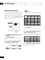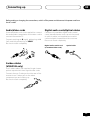
1
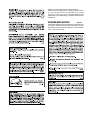
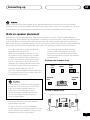
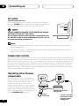
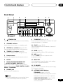
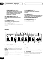
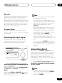
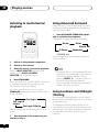
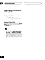
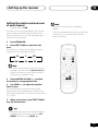
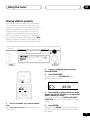
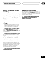
AUDIO/VIDEO MULTI-CHANNEL
RECEIVER
VSX-D411
VSX-D511
Operating Instructions
Thank you for buying this Pioneer product.
Please read through these operating instructions
so you will know how to operate your model
properly. After you have finished reading the
instructions, put them away in a safe place for future
reference.
IMPORTANT NOTICE
H006AEn
The serial number for this equipment is located in the
rear panel. Please write this serial number on your
enclosed warranty card and keep it in a secure area.
This is for your security.
Manufactured under license from Dolby Laboratories.
“Dolby”, “Pro Logic II” and the double D symbol 2
are trademarks of Dolby Laboratorories.
"DTS", “ES” and "DTS Digital Surround" are trademarks
of Digital Theater Systems, Inc.
Contents
1 Before you start
5 Playing sources
Checking what’s in the box ...............................5
Installing the receiver ........................................5
Making cable connections ................................5
Loading the batteries .........................................5
Operating range of remote control unit ........... 5
Introduction to Sound Modes ........................ 24
Stereo/Direct ...............................................24
Standard modes .........................................24
Advanced Surround modes .......................24
Choosing the input signal .............................. 25
Using Stereo/Direct .........................................25
Listening to multi-channel playback ..............26
Using Advanced Surround ............................. 26
Using Loudness and Midnight listening ........26
Using the tone controls .................................. 27
Playing other sources ..................................... 27
Selecting the multi-channel analog inputs ... 28
2 5 minute guide
Introduction to home theater ............................6
Listening to Surround Sound ............................7
Using the Quick Setup ....................................10
3 Connecting up
Audio/Video cords ........................................... 11
S-video cables (VSX-D511 only) ......................11
Digital audio cords/Optical cables .................11
Connecting digital components .................... 12
Connecting audio components ......................12
Connecting DVD 5.1 channel components ... 13
Connecting video components .......................13
Connecting antennas ..................................... 14
FM wire antenna ..............................................14
AM loop antenna ..............................................15
Antenna snap connectors ........................ 15
Using external antennas .................................15
To improve FM reception ............................15
To improve AM reception ...........................15
Connecting the speakers ................................16
Speaker terminals ..................................... 16
Hints on speaker placement ...........................17
AC outlet .......................................................... 18
Operating other Pioneer components .......... 18
4 Controls and displays
Front Panel ........................................................19
Display ............................................................. 20
Remote Control ............................................... 22
6 Setting up your receiver
Choosing your receiver setup ........................ 29
Speaker setting .......................................... 30
Subwoofer setting ..................................... 30
Crossover frequency setting ......................30
LFE attenuator setting ................................31
Front speaker distance setting ..................31
Center speaker distance setting .............. 31
Surround speaker distance setting .......... 31
Dynamic range control setting ..................32
Dual mono setting ..................................... 32
Coaxial digital input setting .......................32
Optical digital input setting .......................32
Setting the relative volume level
of each channel ............................................... 33
7 Using the tuner
Listening to the radio ...................................... 34
Improving FM stereo sound .......................34
Saving station presets .....................................35
Naming station presets .................................. 36
Listening to station presets ............................ 36
8 Making a recording
Making an audio or a video recording .......... 37
Monitoring your recording ........................ 37
9 Additional information
Troubleshooting ............................................... 38
Specifications ...................................................40
Before you start
01
Checking what’s in the box
Please check that you've received the following
supplied accessories:
• AM loop antenna
• FM wire antenna
Incorrect use of batteries may result in such
hazards as leakage and bursting. Observe the
following precautions:
• Never use new and old batteries together.
• Dry cell batteries (AA size IEC R6P) x 2
• These operating instructions
• Insert the plus and minus sides of the
batteries properly according to the marks
in the battery case.
Installing the receiver
• Batteries with the same shape may have
different voltages. Do not use different
batteries together.
• Remote control
Please note the following points:
• Do not place
objects directly
on top of this unit.
This would
prevent proper
heat dispersal.
• When disposing of used batteries, please
comply with governmental regulations or
environmental public instruction’s rules
that apply in your country or area.
STAND
BY
STAND
BY
/ON
PHONE
S
STATION
TUNING
TUNER
EDIT
CLASS
STANDAR
MULTI
D
JOG
BAND
ADVANC
SURROU
ED
ND
MPX
INPUT
G
FL
AUDIO
/VIDEO
MULTI-
STEREO
DIRECT
/
CHANN
SIGNAL
SELECT
LISTENIN
ATT
EL
RECEIV
MODE
DIMMER
ER
MONITOR
MULTI
MIDNIGH
T
N∫m-
Û.,,
JOG
LOUDNE
ENTER
SS
TONE
INPUT
SELEC
QUICK
SETUP
TOR
MULTI
JOG
MASTE
DOWN
R
VOLUM
E
UP
R
• When installing on a rack, shelf, etc., be
sure to leave more than 8 inches (20 cm.)
of space above the receiver.
Making cable connections
Make sure not to bend the cables over the top
of this unit (as shown in the illustration). If this
happens, the
magnetic field
produced by the
transformers in
this unit may
cause a humming
noise from the
speakers.
Operating range of remote
control unit
The remote control may not work properly if:
• There are obstacles between the remote
control and the receiver's remote sensor.
• Direct sunlight or fluorescent light is
shining onto the remote sensor.
• The receiver is located near a device that is
emitting infrared rays.
• The receiver is operated simultaneously
with another infrared remote control unit.
STAN
DBY
STAN
DBY
/ON
PHO
NES
STATIO
N
TUNIN
G
TUNE
R EDIT
CLAS
S
MULTI
JOG
STAND
ARD
BAND
ADVAN
SURROCED
UND
MPX
INPUT
LISTE
NING
ATT
MODE
FL
DIMM
ER
AUD
IO/VI
DEO
STERE
DIRECO/
T
MULT
I-CHA
NNEL
SIGNA
SELECL
T
RECE
IVER
MONIT
OR
MULT
MIDNI
GHT
N∫m
-Û.
I JOG
LOUD
NESS
,,
ENTE
R
30
30
Loading the batteries
TONE
INPU
SELET
CTOR
QUICK
SETU
P
MULTI
JOG
MAS
DOWN
TER
VOLU
ME
UP
R
1
4
2
5
3
6
+
+
-
23ft (7m)
Dry cell batteries
(AA size IEC R6P) × 2
5
En
02
5 minute guide
Introduction to home theater
You are probably used to using stereo equipment to listen to music, but may not be used to home
theater systems that give you many more options (such as surround sound) when listening to
soundtracks.
Home theater refers to the use of multiple audio tracks to create a surround sound effect, making
you feel like you're in the middle of the action or concert. The surround sound you get from a home
theater system depends not only on the speakers you have set up in your room, but also on the
source and the sound settings of the receiver.
DVD-Video has become the basic source material for home theater due to its size, quality, and ease
of use. Depending on the DVD, you can have up to seven different audio tracks coming from one
disc, all of them being sent to different speakers in your system. This is what creates a surround
sound effect and gives you the feeling of ‘being there’.
This receiver will automatically decode Dolby Digital, DTS, or Dolby Surround DVD-Video discs,
according to your speaker setup. In most cases, you won’t have to make changes for realistic
surround sound, but other possibilities (like listening to a CD with multi-channel surround sound)
are explained in Playing sources, starting on page 24.
6
En
5 minute guide
02
Listening to Surround Sound
This receiver was designed with the easiest possible setup in mind, so with the following quick
setup guide, you should have your system hooked up for surround sound in no time at all. In most
cases, you can simply leave the receiver in the default settings.
1
Hook up your DVD player.
For surround sound, you’ll want to hook up using a digital connection from the DVD player to the
receiver. You can do this with either a coaxial, or an optical connection (you don’t need to do both). If
you hook up using an optical cable, you should refer to Optical digital input setting on page 32 to
assign the optical input to DVD.
Use a video cord to connect the video output on your DVD to the receiver using the jacks shown
below.
2
Hook up your TV.
Use a video cord to connect your receiver to the TV using the jacks as shown below.
Optical cable
Coaxial cable
Note: If you hook up
using a optical cable,
see Optical input
setting on page 32 to
assign the optical
input to DVD.
Video cord
ASSIGNABLE
DIGITAL IN
OPT
COAX
(DVD/LD) ¥
DIGITAL OUT
DVD
/ LD
FRONT
VIDEO OUT
S
(T V / S A T ) ¥
This receiver*
IN
DVD
5.1CH
REC INPUT
IN
CD-R
/ TAPE
/ MD
VIDEO
OUT
IN
DVD PLAYER
STANDBY/ON
41
0
¡¢
7
8
MONITOR
OUT
Î
3
SUB
WOOFER
DVD player
PREOUT
*The illustration shows the
VSX-D511, but DVD
connections for both the
VIDEO IN
TV
VSX-D411 and VSX-D411S
Video cord
will be the same.
7
En
02
5 minute guide
3
Connect your speakers.
A complete setup of six speakers (including the subwoofer) is shown here, but everyone’s home
setup will vary. Simply connect the speakers you have in the manner shown below. The receiver will
work with just two stereo speakers (the front speakers in the diagram) but using at least three
speakers is recommended, and all six is best. If you’re not using a subwoofer, change the front
speaker setting (see Speaker setting on page 30) to large.
Make sure you connect the speaker on the right to the right terminal and the speaker on the left to
the left terminal. Also make sure the positive and negative (+/–) terminals on the receiver match
those on the speakers.
Use speakers with a nominal impedance of 8 Ω to 16 Ω.
Front Speakers
L
R
Center Speaker
C
R L
Surround Speakers
SL
SR
R L
INPUT
Powered subwoofer
8
En
Be sure to complete all
connections before
connecting this unit to
the AC power source.
5 minute guide
02
4
Plug in the receiver and switch it on, followed by your DVD player, your subwoofer and
the TV.
Make sure you’ve set the video input on your TV to this receiver. Check the manual that came with
the TV if you don’t know how to do this.
Also make sure that DVD/LD is showing in the receiver’s display, indicating that the DVD input is
selected. If it isn’t, press DVD on the remote control to set the receiver to the DVD input.
5
Press QUICK SETUP on the front panel to specify your speaker setup and your room
size.
Use the MULTI JOG/INPUT SELECTOR dial to select and ENTER to confirm your selection. See
Using the Quick Setup on the next page if you’re unsure about the settings.
6
Play a DVD, and adjust the volume to your liking.
There are several other sound options you can select. See pages 24 to 27 for more on this. See also
Choosing your receiver setup on pages 29 to 33 for more setup options.
Depending on your DVD player or source discs, you may only get digital 2 channel stereo and
analog sound. In this case, the listening mode must be set to Standard (it should already be
set—see page 26 if you need to do this) if you want multi-channel surround sound.
9
En
02
5 minute guide
Using the Quick Setup
You can use the Quick Setup to get your system
up and running with just a few button presses.
The receiver automatically makes the necessary
settings after you have selected your speaker
setup and room size. If you want to make more
specific settings, refer to Choosing your receiver
setup on pages 29 to 33. Use the front panel
controls for the steps below.
Check the table below to find the speaker
setup that corresponds with your system.
Front
Center Surround Sub
Speakers Speaker Speakers Woofer
3.0 ch
3.1 ch
4.0 ch
AUDIO/VIDEO MULTI-CHANNEL RECEIVER
4.1 ch
N∫m-Û.,,
5.0 ch
INPUT
SELECTOR
MULTI JOG
5.1 ch
ENTER
√
√
√
√
√
√
√
√
√
√
√
√
√
√
√
√
√
MASTER VOLUME
T
LOUDNESS
TONE
QUICK SETUP
UP
DOWN
4
Press ENTER.
The display prompts you to select your room
size.
MULTI JOG
R
1
Press RECEIVER to turn the power on.
The STANDBY indicator goes out.
2
Press QUICK SETUP.
The display prompts you to select your speaker
setup.
3
Use the MULTI JOG/INPUT SELECTOR
dial to choose your speaker setup.
Cycle between the following choices:
5.1ch
5.0ch
4.1ch
3.0ch
3.1ch
10
En
4.0ch
5
Use the MULTI JOG/INPUT SELECTOR
dial to choose your room size.
Depending on the distance of your surround
speakers, choose between Small, Medium, or
Large (see table below).
Front
Center
Surround
S
M
L
12 ft.
10 ft.
6 ft.
12 ft.
10 ft.
7 ft.
12 ft.
10 ft.
9 ft.
6
Press ENTER to confirm your setup.
The display shows the speaker setup and room
size that you have selected.
Connecting up
03
Before making or changing the connections, switch off the power and disconnect the power cord from
the AC outlet.
Audio/Video cords
Digital audio cords/Optical cables
Use audio/video cords (not supplied) to connect
the audio/video components and a video cord to
connect the monitor TV.
Commercially available digital audio coaxial
cords (standard video cords can also be used)
or optical cables (not supplied) are used to
connect digital components to this receiver.
Connect red plugs to R (right), white plugs to L
(left), and the yellow plugs to VIDEO.
Be sure to insert completely.
Be sure to insert completely.
R
Digital audio coaxial cord
(or standard video cord)
Optical cable
L
VID
EO
S-video cables
(VSX-D511 only)
Use S-video cables (not supplied) to get clearer
picture reproduction than regular video cords.
Connect from an S-video jack on the rear of the
receiver to an S-video jack on the video
component you are hooking up.
Be sure to insert completely.
SV
IDE
O
11
En
03
Connecting up
Connecting digital components
For proper decoding of Dolby Digital/DTS soundtracks, you need to make digital audio connections.
You can do this by either coaxial or optical connections (you don’t need to do both). The quality of
these two types of connections is the same, but since some digital components only have one type
of digital terminal, it is a matter of matching like with like (for example, the coaxial output from the
component to the coaxial input on the receiver). This receiver has both a coaxial and an optical
input for a total of two digital inputs. Connect your digital components as shown below.
When connecting your equipment, always make sure the power is turned off and the power cord is
disconnected from the wall outlet.
DIGITAL
OUT
(OPTICAL)
CD player
The arrows
indicate the
direction of the
audio signal.
DIGITAL
OUT
(COAXIAL)
DVD player
Connecting audio components
To begin set up, connect your analog audio components (such as a cassette deck) to the jacks. For
components you want to record with, you need to hook up four plugs (a set of stereo ins and a set of
stereo outs), but for components that only play, you only need to hook up one set of stereo ins (two
plugs). You should also hook up your digital components to analog audio jacks if you want to record
to/from digital components (like an MD) to/from analog components. See above for more on digital
connections.
When connecting your equipment, always make sure the power is turned off and the power cord is
disconnected from the wall outlet.
ANALOG
OUT
CD player
ANALOG
IN (REC)
CD-R/Tape/MD Deck
12
En
ANALOG
OUT (PLAY)
The arrows
indicate the
direction of the
audio signal.
Connecting up
03
Connecting DVD 5.1 channel components
If you prefer to use a seperate component for decoding DVDs, you can connect a decoder or a DVD
player with multi-channel analog outputs to the multi-channel inputs of this receiver.
When connecting your equipment, always make sure the power is turned off and the power cord is
disconnected from the wall outlet.
CENTER
OUTPUT
SUBWOOFER
OUTPUT
SURROUND
OUTPUT DVD/multi-channel decoder
VIDEO with 5.1 channel analog
OUTPUT output jacks
The arrows
indicate the
direction of
the signal.
FRONT
OUTPUT
The 5.1 channel input can only be used when DVD 5.1 CH is selected (see page 28).
Connecting video components
Connect your video components to the jacks as shown below. Regarding digital video components
(like a DVD player), you must use the connections pictured on this page for the video signal, but in
order to hear a digital source (like a DVD) you should hook up the audio to a digital input (see page
12). It is also a good idea to hook up your digital components with analog audio connections (see
page 12).
For better quality video, you can hook up using the S-video jacks on the rear of the receiver instead
of the regular video jacks (VSX-D511 only). Make sure you use an S-video cable to connect to the Svideo jack on the component you are hooking up (see page 11).
When connecting your equipment always make sure the power is turned off and the power cord is
disconnected from the wall outlet.
AUDIO
INPUT
VIDEO
INPUT
S-VIDEO
INPUT
S-VIDEO
OUTPUT
VIDEO
OUTPUT
AUDIO
OUTPUT
Video deck
The arrows
indicate the
direction of
the signal.
13
En
03
Connecting up
AUDIO
OUTPUT
VIDEO
OUTPUT
S-VIDEO TV tuner (or Satellite tuner)
OUTPUT
The arrows
indicate the
direction of
the signal.
S-VIDEO
OUTPUT
VIDEO
OUTPUT
AUDIO DVD player (or LD player)
OUTPUT
S-VIDEO
INPUT
The arrows
indicate the
direction of
the signal.
VIDEO
INPUT
TV (monitor)
Connecting antennas
Connect the AM loop antenna and the FM wire
antenna as shown at right. To improve reception
and sound quality, connect external antennas
(see Using external antennas, next page).
Always make sure that the receiver is switched
off and unplugged from the wall outlet before
making or changing any connections.
AM LOOP
ANTENNA
FM wire antenna
Connect the FM wire antenna and fully extend
vertically along a window frame or other
suitable area, etc.
FM WIRE
ANTENNA
14
En
Connecting up
03
AM loop antenna
Using external antennas
Assemble the antenna and connect to the
receiver. Attach to a wall, etc. (if desired) and
face in the direction that gives the best
reception.
To improve FM reception
Connect an external FM antenna.
FM
UNBAL
75Ω
Antenna snap connectors
75 Ω coaxial cable
Twist the exposed wire strands together and
insert into the hole, then snap the connector
shut.
FM
ANTENNA
To improve AM reception
Connect a 15-18 feet length of vinyl-coated wire
to the AM antenna terminal without disconnecting the supplied AM loop antenna.
3/8 in. (10mm)
For the best possible reception, suspend
horizontally outdoors.
Outdoor antenna
Indoor antenna
(Vinyl-coated wire)
15-18 ft. (5–6m)
AM LOOP
ANTENNA
15
En
03
Connecting up
Connecting the speakers
A complete setup of six speakers (including the subwoofer) is shown here, but everyone’s home
setup will vary. Simply connect the speakers you have in the manner shown below. The receiver will
work with just two stereo speakers (the front speakers in the diagram) but using at least three
speakers is recommended, and a complete setup is best for surround sound. If you’re not using a
subwoofer, change the front speaker setting (see Speaker setting on page 30) to large.
Make sure you connect the speaker on the right to the right terminal and the speaker on the left to
the left terminal. Also make sure the positive and negative (+/–) terminals on the receiver match
those on the speakers.
Front Speakers
L
Center Speaker
R
Surround Speakers
C
SL
SR
Use speakers with
a nominal
impedance of 8 Ω
to 16 Ω.
R L
R L
INPUT
Be sure to complete all other
connections before connecting this
unit to the AC power source.
Powered subwoofer
Speaker terminals
16
En
1
Twist around 1/2 inch of bare wire strands together.
2
Unclip the speaker terminal and insert the wire.
3
Snap shut the speaker terminal to secure.
ª
1/2 inches
·
Connecting up
03
Make sure that all the bare speaker wire is twisted together and inserted fully into the speaker
terminal. If any of the bare speaker wire touches the rear panel it may cause the power to cut off as
a safety measure. Use good quality speaker wire to connect the speakers to the receiver.
Hints on speaker placement
Speakers are usually designed with a particular placement in mind. Some are designed to be
floorstanding, while others should be placed on stands to sound their best. Some should be placed
near a wall; others should be placed away from walls. We have provided a few tips on getting the
best sound from your speakers (below), but you should also follow the guidelines on placement that
the speaker manufacturer provided with your particular speakers to get the most out of them.
• Place the front left and right speakers at
equal distances from the TV.
• When placing speakers near the TV, we
recommend using magnetically shielded
speakers to prevent possible interference,
such as discoloration of the picture when
the TV is switched on. If you do not have
magnetically shielded speakers and notice
discoloration of the TV picture, move the
speakers farther away from the TV.
• To achieve the best possible surround
sound, install your speakers as shown
below. Be sure all speakers are installed
securely to prevent accidents and improve
sound quality.
Overhead view of speaker set up
Front
Left
Center
• Place the center speaker above or below the
TV so that the sound of the center channel is
localized at the TV screen.
Subwoofer
Surround
Left
If you choose to install the center speaker
on top of the TV, be sure to secure it with
putty, or by other suitable means, to
reduce the risk of damage or injury
resulting from the speaker falling from
the TV in the event of external shocks
such as earthquakes.
Front
Right
Surround
Right
Listening Position
3-D view of speaker set up
• If possible, place the surround speakers
slightly above ear level.
• Try not to place the surround speakers
further away from the listening position than
the front and center speakers. Doing so can
weaken the surround sound effect.
17
En
03
Connecting up
AC outlet
[switched 100 W (0.8 A) max]
Power supplied through this outlet is turned on and off by the
receiver's POWER switch. Total electrical power consumption of
connected equipment should not exceed 100 W (0.8 A).
AC OUTLET
SWITCHED
100 W MAX
0.8 A MAX
DO NOT CONNECT A MONITOR, TV SET, HEATER, OR SIMILAR
APPLIANCE TO THIS UNIT'S AC OUTLET.
Do not connect appliances with high power consumption to the
AC OUTLET in order to avoid overheating and fire risk. This can
also cause the receiver to malfunction.
• Make sure no exposed speaker wire is touching the rear panel, this may cause the receiver to
turn off automatically.
• This unit should be disconnected by removing the power plug from the wall socket when not in
regular use (ex. when on vacation).
POWER-CORD CAUTION
Handle the power cord by the plug. Do not pull out the plug by tugging the cord and never touch the
power cord when your hands are wet as this could cause a short circuit or an electric shock. Do not
place the unit, a piece of furniture, etc., on the power cord, or pinch the cord. Never make a knot in
the cord or tie it with other cords. The power cords should be routed such that they are not likely to
be stepped on. A damaged power cord can cause a fire or give you an electrical shock. Check the
power cord once in a while. When you find it damaged, ask your nearest Pioneer authorized service
center or your dealer for a replacement.
Operating other Pioneer
components
By connecting a control cord (optional),
you can point the remote controls of other
Pioneer components at the receiver’s
remote sensor. You can also use the
remote control from this unit to control a
Pioneer DVD player. The remote control
signals are received by the remote sensor
of this unit, and sent to the other devices
via the CONTROL OUT terminal.
CONTROL
CONTROL
IN
OUT
OUT
Receiver
Other Pioneer products
with Î mark
Remote
control unit
18
En
Connect to CONTROL
IN terminal of other
Pioneer products
with Î mark.
Controls and displays
04
Front Panel
1
2
4
3
5
6
7
AUDIO/VIDEO MULTI-CHANNEL RECEIVER
N∫m-Û.,,
INPUT
SELECTOR
MULTI JOG
ENTER
STANDBY
STANDBY/ON
MASTER VOLUME
STATION
STANDARD
TUNING
ADVANCED
SURROUND
STEREO/
DIRECT
SIGNAL
SELECT
MONITOR
MIDNIGHT
LOUDNESS
TONE
QUICK SETUP
DOWN
LISTENING MODE
TUNER EDIT
PHONES
CLASS
BAND
MPX
INPUT ATT
UP
MULTI JOG
FL DIMMER
MULTI JOG
R
8
9 10 11 12 13 14 15 16 17 18 19 20 21
1
STANDBY/ON
Switches the receiver between on and standby.
2
STANDBY indicator
Lights when the receiver is in standby mode.
3
STATION (+/–) buttons (pages 35–36)
Selects station presets when using the tuner.
4
TUNING (+/–) buttons (page 34)
Selects the frequency when using the tuner.
5
Remote sensor
Receives the signals from the remote control.
6
ENTER
7
MULTI JOG/INPUT SELECTOR dial
The MULTI JOG/INPUT SELECTOR dial
performs a number of tasks. Use it to select
options after pressing TONE CONTROL, QUICK
SETUP or TUNER EDIT.
8
PHONES jack
Use to connect headphones.
22
9
TUNER EDIT (pages 35–36)
Press to memorize and name a station for recall
using the station (+/–) buttons.
10 CLASS (pages 35–36)
Switches between the three banks (classes) of
station presets.
11 BAND (page 34)
Switches between AM and FM radio bands.
12 MPX (page 34)
Press the MPX button to receive a radio
broadcast in mono.
13 INPUT ATT
Use to attenuate (lower) the level of an analog
input signal to prevent distortion.
14 FL DIMMER
Use this button to make the fluorescent display
(FL) dimmer or brighter.
15
LISTENING MODE buttons
STANDARD (pages 24, 26, 33)
Press for Standard decoding and to switch
between the various Pro Logic II options.
When the headphones are connected, there
is no sound output from the speakers.
ADVANCED SURROUND (pages 24, 26)
Use to switch between the various
surround modes.
19
En
04
Controls and displays
STEREO/DIRECT (pages 24–25)
Switches direct playback on or off. Direct
playback bypasses the tone controls and
channel levels for the most accurate
reproduction of a source.
19 LOUDNESS (page 26)
Use to boost the bass and treble at low
volumes.
20 TONE (page 27)
Press this button to access the bass and treble
controls, which you can then adjust with the
MULTI JOG/INPUT SELECTOR dial.
16 SIGNAL SELECT (page 25, 28)
Use to select between an analog or digital
signal.
17 MONITOR (page 37)
Press to switch tape monitoring on/off.
21
QUICK SETUP (page 10)
22
MASTER VOLUME
18 MIDNIGHT (page 26)
Use when listening to movie soundtracks at low
volumes.
Display
2
1
SIGNAL AUTO
DIGITAL
DIGITAL
ANALOG DTS
3
4
DIGITAL
PROLOGIC
ADV.SURR.
5
ATT
6
7
8
9
DIRECT MONITOR
MIDNIGHT STEREO
LOUDNESS MONO
TUNED
SP
A
dB
10
1
SIGNAL SELECT indicators
Lights to indicate the type of input signal
assigned for the current component:
AUTO : Lights when AUTO signal select is on.
DIGITAL : Lights when a digital audio signal is
detected.
2 DIGITAL : Lights when a Dolby Digital signal
is detected.
ANALOG : Lights when an analog signal is
detected.
20
En
11
12
13
14
DTS : Lights when a source with DTS audio
signal is detected.
2
DTS
When the Standard mode of the receiver is on,
this lights to indicate decoding of a DTS signal.
3
2 DIGITAL
When the Standard mode of the receiver is on,
this lights to indicate decoding of a Dolby
Digital signal.
Controls and displays
04
4
2 PRO LOGIC II
When the Standard mode of the receiver is on,
this lights to indicate Prologic II decoding.
11 ADV. SURR (Advanced Surround)
Lights when one of the Advanced Surround
listening modes of the receiver is selected.
5
ATT
Lights when INPUT ATT is used to attenuate
(reduce) the level of the input signal (can only
be used with an analog signal).
12 LOUDNESS
Lights during Loudness listening.
6
DIRECT
Lights when source direct playback is in use.
This function bypasses all tone, balance, DSP
and Dolby Surround effects.
7
MIDNIGHT
Lights during Midnight listening.
8
MONITOR
Lights when MONITOR is selected.
9
Speaker indicator
Shows if the speaker system is on or not.
SP 3A means speakers are switched on. SP 3
means the headphones are connected.
10
Character display
13 TUNER indicators
STEREO : Lights when a stereo FM broadcast is
being received in auto stereo mode.
MONO : Lights when the mono mode is set
using the MPX button.
TUNED : Lights when a broadcast is being
received.
14 Master volume level
Shows the overall volume level. --- dB indicates
the minimum level, and – 0dB indicates the
maximum level.
Depending on the level settings you make for
each channel, the maximum level can
range between –10dB and – 0dB.
21
En
04
Controls and displays
ADVANCED SURROUND (page 24, 26)
Use to switch between the various
surround modes.
Remote Control
STEREO/DIRECT (pages 24–25)
Switches direct playback on or off. Direct
playback bypasses the tone controls and
channel levels for the most accurate
reproduction of a source.
DVD/LD TV/SAT
1
8
2
3
4
5
MASTER
VOLUME
ATT
STATION
10
CLASS
MPX
MENU
7
DISPLAY
TOP MENU
TUNER
EDIT
11
12
SETUP
ENTER
VER
DVD
13
DVD
CH SELECT
EFFECT
AUDIO
14
SUB TITLE
7
1
3
¡
8
4
¢
15
DVD CONTROL
AV RECEIVER
Î
1
RECEIVER
Switches the receiver between on and standby.
2
MIDNIGHT/LOUDNESS (page 26)
Use to switch to Midnight or Loudness
listening.
3
LISTENING MODE buttons
STANDARD (page 24, 26, 33)
Press for Standard decoding and to switch
between the various Pro Logic II options.
22
En
4
INPUT ATT
Use to attenuate (lower) the level of an analog
input signal to prevent distortion.
9
MUTE
TUNING
BAND
6
CD
5
FL DIMMER
Use this button to make the fluorescent display
(FL) dimmer or brighter.
6
MENU (DVD control)
Use to access different menus associated with
your DVD player.
TUNER EDIT (Receiver control) (pages 35–
36)
Press to memorize and name a station for recall
using the STATION (+/–) buttons.
7
DVD
Use to switch over to the DVD controls on the
remote control.
The DVD controls on the remote control (TOP
MENU, MENU, } ] ’ ‘ and ENTER/SETUP
buttons) can only be used for DVD control after
pressing DVD on the remote. See the next page
for more on the seperate DVD CONTROL
buttons.
8
INPUT SELECTOR buttons
Use to select the input source.
9
Volume buttons
Use MASTER VOLUME +/– to set the overall
listening volume. Use MUTE to mute the sound
or restore the sound if it has been muted.
Controls and displays
04
EFFECT +/– (page 26)
Use to add or subtract the amount of effect
in different sound modes or advanced
listening modes.
10 Tuner controls
The TUNING +/– buttons can be used to find
radio frequencies. The STATION +/– buttons
can be used to select preset radio stations
(pages 35–36).
BAND (page 34)
Use to switch between the AM and FM
bands when the tuner is selected.
CLASS (pages 35–36)
Use to switch between the three banks
(classes) of station presets.
MPX (page 34)
Use to switch between auto stereo and
mono reception of FM broadcasts. If the
signal is weak then switching to mono will
improve the sound quality.
DISPLAY (page 36)
Use to switch the display between the
station preset name and the frequency.
11 TOP MENU
Displays the disc ‘top’ menu of a DVD.
12 } ] ’ ‘ and ENTER/SETUP buttons
Use these arrow buttons when setting up your
surround sound system. These buttons are also
used to control DVD menus/options.
13 RECEIVER
Use to switch to the receiver controls on the
remote control. Also used when setting up the
surround sound for the receiver.
15 DVD CONTROL buttons
You can use these buttons to control a Pioneer
DVD player connected to your system.
Button
What it does
DVD
Turns DVD power on/off.
AUDIO
Changes the audio language or
channel.
SUBTITLE
Displays/changes the subtitles
included in multilingual DVDVideo discs.
1
Press to start fast reverse
scanning.
3
Starts playback.
¡
Press to start fast forward
scanning.
7
Stops playback.
8
Pauses a disc that’s playing, or
restarts a paused disc.
4
Skips to the start of the current
track or chapter, then to
previous tracks/chapters.
¢
Skips to the next track or
chapter.
14 CHANNEL SELECT (page 33)
Use to select a channel when setting up the
surround sound of the receiver.
TEST TONE (page 33)
Use to sound the test tones when setting
up the surround sound of the receiver.
LEVEL +/– (page 33)
Use to set up the levels of the surround
sound of the receiver.
23
En
05
Playing sources
Introduction to Sound Modes
There are three basic sound options: Stereo/
Direct, Standard or Advanced Surround.
Stereo/Direct
When you select STEREO or DIRECT, you will
hear the source through just the front left and
right speakers (and possibly your subwoofer
depending on your speaker settings). Dolby
Digital and DTS multi-channel sources are
downmixed to stereo.
In STEREO, the audio plays according to the
surround setup settings and you can still use
Midnight mode, Loudness mode and Tone
Control functions.
When you select DIRECT, the audio bypasses
the tone controls and channel levels for the
most accurate reproduction of a source.
Standard modes
The Standard mode can be used to decode
Dolby Digital, DTS or Dolby Surround sources.
The surround mode options (below) can also
add surround sound to regular stereo sources.
You can identify Dolby Digital software by the
marks. Most Dolby
1 or
Surround software is marked 3, but
unmarked software may also incorporate Dolby
Surround.
Choose one of the following to add depth to a 2
channel source:
Pro Logic II Movie
This mode gives 5.1 channel surround sound. It
is suitable for movies, especially those recorded
in Dolby Surround. The channel separation and
movement of surround effects is comparable to
Dolby Digital 5.1.
Pro Logic II Music
This mode gives 5.1 channel surround sound
and is suitable for music. Compared to Pro
Logic II Movie, the surround effect is more
enveloping.
Advanced Surround modes
These are designed to be used with multi
channel surround sound audio/visual sources
(like DVDs and LDs). Most Advanced Surround
modes are designed to be used with film
soundtracks, but some modes are also suited
for music sources. Try different settings with
various soundtracks to see which you like.
Movie
Simulates the relaxed environment of a movie
theater, and is suitable for watching movies on
R
sources marked 1 (
) or
.
Music
Simulates the acoustic environment of a large
concert hall and is suitable for music or
musical sources marked 1 (
) or
R
Pro Logic
This mode gives 4.1 channel surround sound. It
is less sensitive to the quality of the source
material, so may be useful when Pro Logic II
Movie/ Music modes do not give good results.
24
En
.
Virtual Surround Back (VIRTL SB)
(VSX-D511 only)
The Virtual Surround Back effect simulates 6.1
surround channel listening, giving the impression that there is a surround back speaker in
your system when listening to a 5.1 channel
source.
Playing sources
05
Expanded
This mode is especially designed to give sound
depth to stereo sources. The overall effect
builds a dynamic and broad sound space,
allowing two-channel (stereo) signals to imitate
a five speaker sound. Use with Dolby Pro Logic
for a stereo surround effect. You can also use
with Dolby Digital sources for a wider stereo
field than the Standard modes.
5-Channel Stereo
This can be selected to give multi-channel
sound to a stereo source, using all the speakers
in your setup.
Choosing the input signal
You need to hook up a component to both
analog and digital inputs on the back of the
receiver to select between input signals.
AUDIO/VIDEO MULTI-CHANNEL RECEIVER
MASTER VOLUME
SIGNAL
SELECT
MONITOR
MIDNIGHT
LOUDNESS
TONE
QUICK SETUP
DOWN
• You may get digital noise when a LD or CD
player compatible with DTS is playing an
analog signal. To prevent noise, make the
proper digital connections (page 12) and
set the signal input to DIGITAL.
• Some DVD players don’t output DTS
signals. For more details, refer to the
instruction manual supplied with your DVD
player.
• You can only select DIGITAL if the source
you selected is assigned to a digital input.
See page 32 for more on the digital input
settings.
Using Stereo/Direct
ENTER
STEREO/
DIRECT
• This receiver can only play back Dolby
Digital, PCM (32kHz, 44kHz, 48kHz, and 96
kHz) and DTS digital signal formats. With
other digital signal formats, set to
ANALOG.
N∫m-Û.,,
INPUT
SELECTOR
MULTI JOG
• DVD 5.1 ch is only available when DVD/LD
is selected as the source.
UP
MULTI JOG
R
•
Press SIGNAL SELECT (front panel) to
select the input signal corresponding to the
source component.
Each press switches between AUTO, DVD 5.1
ch, ANALOG and DIGITAL. The default is
AUTO.
When set to DIGITAL, 2 DIGITAL lights when
a Dolby Digital signal is input, and DTS lights
when a DTS signal is input.
When you select STEREO or DIRECT, you will
hear the source through just the front left and
right speakers (and possibly your subwoofer
depending on your speaker settings). Dolby
Digital and DTS multichannel sources are
downmixed to stereo. See the previous page for
more on these modes.
•
Press STEREO (STEREO/DIRECT on the
front panel) repeatedly to switch between
the two options.
If you switch on Midnight listening, Loudness, or the Tone controls when DIRECT is
selected, the receiver automatically
switches to STEREO.
25
En
05
Playing sources
Listening to multi-channel
playback
INPUT SELECTOR
CD
Using Advanced Surround
Dolby Pro Logic, Dolby Digital and DTS signal
processing is done automatically corresponding to the input signal.
•
Press ADVANCED SURROUND repeatedly to cycle the sound options.
Each press changes the display as follows:
RECEIVER DVD/LD TV/SAT
CD-R/
VCR/
DVR
Movie
Music
STANDARD
Virtual SB*
5-Stereo
Expanded
*VSX-D511 only.
Refer to page 24 for more details about each
surround effect.
1
Switch on the playback component.
2
Switch on the receiver.
3
Select the source you want to playback.
Use the INPUT SELECTOR buttons on the
remote (or the MULTI JOG/INPUT
SELECTOR dial on the front panel).
4
Press STANDARD.
For multi-channel sources, Dolby/DTS decoding
is selected automatically according to the
source and shows in the display.
For a two channel source, you can press
STANDARD repeatedly to select the Pro Logic II
mode you want:
Pro Logic
Pro Logic II
Music
Pro Logic II Movie
Refer to page 24 for more details about each
mode.
5
Start playback of the component you
selected in step 1.
26
En
• The Movie, Music, and Expanded effects of
Dolby/DTS can be adjusted in the range of
10 to 90 (the default setting is 70) by
pressing EFFECT +/– . The effect level can
be set for each of these Advanced
Surround mode. The Standard and Stereo
modes cannot be changed.
Using Loudness and Midnight
listening
The Loudness listening feature can be used to
get good bass and treble from music sources at
low volume levels.
The Midnight listening feature allows you to
hear effective surround sound of movies at low
volume levels. The effect automatically adjusts
according to the volume at which you’re
listening.
Playing sources
05
•
Press MIDNIGHT/LOUDNESS.
Each press cycles through the effects as
follows:
• The tone controls can only be used with
the Stereo sound mode.
Midnight
• When the receiver is switched to Direct,
using the tone controls automatically
switches the receiver to Stereo mode.
Off
Loudness
You can also press MIDNIGHT or LOUDNESS
on the front panel. Each press switches the
effect on or off.
Playing other sources
Using the tone controls
Depending on what you are listening to, you
may want to adjust the bass or treble using the
front panel tone control.
AUDIO/VIDEO MULTI-CHANNEL RECEIVER
INPUT SELECTOR
CD
RECEIVER DVD/LD TV/SAT
CD-R/
VCR/
DVR
N∫m-Û.,,
INPUT
SELECTOR
MULTI JOG
ENTER
MASTER VOLUME
MIDNIGHT
LOUDNESS
TONE
QUICK SETUP
DOWN
UP
MULTI JOG
1
Turn on the power of the playback
component.
R
1
Press TONE to select the frequency you
want to adjust.
Each press switches between BASS and
TREBLE.
2
Turn on the power of the receiver.
3
Select the source you want to playback.
Use the INPUT SELECTOR buttons on the
remote (or the MULTI JOG/INPUT SELECTOR
dial on the front panel).
4
Start playback of the component you
selected in step 1.
2
Use the MULTI JOG/INPUT SELECTOR
dial to change the amount of bass or treble
as necessary.
Wait about five seconds for your changes to be
input automatically.
27
En
05
Playing sources
Selecting the multi-channel
analog inputs
Connect a DVD player with 5.1 channel output
to listen to 5.1 channel playback.
1
Select DVD/LD if it is not already
selected.
Use the INPUT SELECTOR buttons on the
remote (or the MULTI JOG/INPUT SELECTOR
dial on the front panel).
2
Press SIGNAL SELECT (front panel)
repeatedly to select 5.1 ch.
To cancel 5.1 channel playback, use the SIGNAL
SELECT button to select an input signal (other
than DVD 5.1 ch).
• When 5.1 channel playback is selected,
you can’t use the SIGNAL SELECT, INPUT
ATT, TONE, and MIDNIGHT/LOUDNESS
buttons, as well as the Standard, Advanced
Surround, and Stereo/Direct sound modes.
• When 5.1 channel playback is selected,
only the volume and channel levels can be
set.
28
En
Setting up the receiver
Choosing your receiver setup
Even though you may already have your system
up and running after using the 5 minute guide
on pages 6 to 10, you should also be sure to
complete the following set up operations to
ensure the best possible surround sound. This
is particularly important when using Dolby
surround. You only need to make these settings
once (unless you change the placement of your
current speaker system or add new speakers,
etc.). Refer to the following pages for details on
each of the settings.
If you are using the Pioneer S-FCRW220
speaker system, you’ll have to set the
Crossover frequency to 200kHz. You can
leave the Speaker setting and the
Subwoofer setting in the default settings.
06
It will be easiest to adjust each of the settings in
turn, following the order below (and on the
following pages). The current setting is shown
for each option as you cycle through the
display.
Speaker setting (page 30)
Specify the number and type of speakers you
have connected.
Subwoofer setting (page 30)
Specify how the subwoofer is used.
Crossover frequency setting (page 30)
Determine which frequencies will be sent to the
subwoofer (or large speakers).
LFE attenuator setting (page 31)
Specify the peak level for the LFE channel.
Front speaker distance setting (page 31)
Specify the distance from your listening
position to your front speakers.
Center speaker distance setting (page 31)
Specify the distance from your listening
position to your center speaker.
RECEIVER
Surround speaker distance setting (page 31)
Specify the distance from your listening
position to your surround speakers.
Dynamic range control setting (page 32)
Compress the dynamic range of the sound
track.
ENTER
RECEIVER
1
Press RECEIVER to turn the power on.
The STANDBY indicator goes out.
2
Press RECEIVER.
3
Use } or ] to choose the option you
want to adjust.
Dual mono setting (page 32)
Isolate one channel when listening to discs with
dual mono encoding.
Coaxial digital input setting (page 32)
Specify the component to be assigned to the
coaxial digital input.
Optical digital input setting (page 32)
Specify the component to be assigned to the
optical digital input.
29
En
06
Setting up the receiver
4
Use ’ or ‘ to adjust the setting.
The setting is entered automatically.
5
Repeat steps 3 and 4 to set other
surround modes.
6
When you’re done, press ENTER to exit.
The setting display is automatically exited
after 20 seconds of inactivity.
• If the cone size (diameter) of the speaker is
larger than 5 inches, set the speaker size
to L.
• If you’re not using a subwoofer, we
recommend setting the front speakers to L.
Subwoofer setting
• Default setting: ON
You can choose whether the subwoofer is used
or not. Use the plus (PLS) setting for extra bass.
Speaker setting
• Default setting: S (all speakers)
You must let the receiver know how many
speakers you have, and how big they are. The
size you choose (large or small) determines
how much bass is sent from the receiver to the
speakers.
In the display, F, C, and S refer to front, center,
and surround speakers respectively. Speaker
size is denoted as L for large speakers, S for
small speakers, and (asterisk) if no speaker is
connected.
•
Cycle through the available choices
using ’ or ‘ and choose a configuration
that matches your speaker setup.
One of the following configurations should
match your setup:
FS-CS-SS
30
En
•
Use ’ or ‘ to select subwoofer ON, PLS
or OFF.
• If you chose the small front speaker
setting, SUBWF ON is automatically set
and locked.
• When you select the plus setting, you will
get the bass sounds from the subwoofer
even if the front speakers are set to L.
Crossover frequency setting
• Default setting: 100 Hz
Crossover frequency is the point where the
receiver divides the high and low sounds (the
frequencies) between the speakers. Since most
smaller speakers can’t handle deep bass tones,
you can send these sounds to the subwoofer (or
if you don’t have a subwoofer, the large (L)
speakers in your system) instead of the
speakers set to small (S) in your setup. Choose
the point at which you want the frequency
routed to the subwoofer (or L speakers).
FL-C -SS
FS-CS-S
FL-C -SL
FS-C -SS
FL-CS-S
FL-CL-SL
FL-CS-SS
FL-CL-SS
We recommend setting this to 200 Hz if your S
speakers are smaller bookshelf-type speakers.
FL-CS-SL
FL-CL-S
•
Use ’ or ‘ to specify the crossover
frequency for your small speakers (100 Hz,
150 Hz or 200 Hz).
Setting up the receiver
100Hz
150Hz
06
Front speaker distance setting
• Default setting: 10 ft.
Sets the distance from the front speakers to the
listening position.
200Hz
100 Hz
Sends bass frequencies below 100 Hz to the
subwoofer (or L speakers).
150 Hz
Sends bass frequencies below 150 Hz to the
subwoofer (or L speakers).
200 Hz
Sends bass frequencies below 200 Hz to the
subwoofer (or L speakers).
If all speakers (front, center, and surround)
are set to L, the crossover frequency can’t
be set because there are no S speakers
(
appears in the display).
•
Use ’ or ‘ to set the distance of the
front speakers from the main listening
position (within a 30 foot range).
Center speaker distance setting
•
Default setting: 10 ft.
The center speaker is normally placed directly
in the front of the listening room and closer to
the listening position than the front speakers.
This means that the sound from the center
speaker will be heard before the front speakers.
To prevent this, set the center speaker distance
setting to delay the sound from the center
speaker so that the sound from the front and
center speakers will be heard at the same time.
•
Use ’ or ‘ to set the distance of the
center speaker from the main listening
position (within a 30 foot range).
LFE attenuator setting
• Default setting: 0 dB
Dolby Digital and DTS audio sources include
ultra-low bass tones. Set the LFE attenuator as
necessary to prevent the ultra-low bass tones
from distorting the sound from the speakers.
•
Use ’ or ‘ to set the attenuation level
(0 dB, 10 dB or
dB(∞)).
0 dB
10 dB
∞ (displays
)
When ∞ is selected (
appears in the
display), LFE is not available.
When C is selected in the speaker setting,
the center distance can’t be set.
Surround speaker distance setting
• Default setting: 10 ft.
Like the center speaker, you should set the
distance of the surround speakers accurately to
hear sounds coming from both front and
surround speakers at the same time.
•
Use ’ or ‘ to set the distance of the
surround speakers from the main listening
position (within a 30 foot range).
31
En
06
Setting up the receiver
When S is selected in the speaker setting,
the surround distance cannot be set.
ch 1. R ch 2 setting, the left front speaker will
play channel 1 and the right front speaker will
play channel 2.
•
Use ’ or ‘ to cycle through the
possible DUAL MONO settings.
Dynamic range control setting
• Default setting: OFF
Dynamic range is the difference between the
loudest and softest sounds in any given signal.
With this setting, you can compress the
dynamic range, so that low level sounds can be
heard more easily (sounding relatively louder)
yet louder sounds won’t be too overbearing.
L ch 1.R ch 2
ch2
ch1
Coaxial digital input setting
• Default setting: DVD
•
Press ’ or ‘ to set the dynamic range
control (OFF, MAX, or MID).
Here you tell the receiver what component you
have hooked up to the coaxial digital input jack.
• When listening at low volumes, set to
MAX for maximum dynamic range
compression.
•
Use ’ or ‘ to select the coaxial digital
input (DVD, TV, CD, CD-R, VCR or OFF).
After you assign a component to the digital
jack, whenever you select that component, for
example a DVD player, the receiver automatically changes to the digital input setting and
DIGITAL shows in the display.
• Dynamic range control is effective only
when a Dolby Digital signal is being played
back.
Optical digital input setting
Dual mono setting
• Default setting: ch1
The dual mono setting can only be used when
listening to Dolby Digital discs with dual mono
encoding. These discs are not widely used, but
are sometimes used when it is necessary to
have one language on one channel and a
different language on the other. With this
setting you can choose which channel in the
dual mono setting you want to listen to.
If Dolby Digital mode is switched on, you will
hear the channel you have selected (either ch1
or ch2) through your center speaker. With Dolby
Digital mode off, or if you don’t have a center
speaker, you will hear the channel you have
selected through both front speakers. In the L
32
En
• Default setting: TV
Here you tell the receiver what component you
have hooked up to the optical input jack.
•
Use ’ or ‘ to select the optical digital
input (DVD, TV, CD, CD-R, VCR, or OFF).
After you assign a component to the digital
jack, whenever you select that component, for
example a DVD player, the receiver automatically changes to the digital input setting and
DIGITAL shows in the display.
Setting up the receiver
Setting the relative volume level
of each channel
• Default setting: 0 dB
For best surround sound playback, you should
set the relative channel levels from the main
listening position. You can set seperate levels
for each surround mode.
1
06
• Test tone is only output in Standard
modes.
• Since the subwoofer transmits an ultra-low
frequency its sound may seem quieter
than it actually is.
Press STANDARD.
2
Press TEST TONE to output the test
tone.
The test tone is output in the following order
(depending on the speaker setting):
FL
SW
C
FR
SL
SR
STANDARD
MASTER
VOLUME
If you don’t hear a test tone from one of your
speakers, please refer to Speaker setting on
page 30 to make sure you have correctly
specified your speaker setup.
3
Press MASTER VOLUME +/– to adjust
the volume to an appropriate level.
4
Use LEVEL +/– to adjust the speaker
levels in turn.
You should hear the test tone at the same
volume from each speaker when seated in the
main listening position. The channel level range
is ± 10 dB.
Î
5
When you’re done, press TEST TONE to
turn off the test tone.
The speaker volume can be adjusted without
outputting the test tone by pressing CH
SELECT and then using LEVEL +/–.
33
En
07
Using the tuner
Listening to the radio
The following steps show you how to tune to FM
and AM radio broadcasts using the automatic
(search) and manual (step) tuning functions.
Once you are tuned to a station you can
memorize the frequency for recall later—see
Saving station presets on the next page for more
on how to do this.
Manual tuning
To change the frequency one step at a
time, press the TUNING +/– buttons.
High speed tuning
Press and hold the TUNING + / – buttons
for high speed tuning. Release the button
at the frequency you want.
Improving FM stereo sound
If the TUNED or STEREO indicators don't light
when tuning to an fm station because the
signal is weak, press the MPX button to switch
the receiver into mono reception mode. This
should improve the sound quality and allow you
to enjoy the broadcast.
TUNER
TUNING
BAND
MPX
1
Press the TUNER button on the remote
control to select the tuner.
You can also use the MULTI JOG/INPUT
SELECTOR dial on the front panel.
2
Use the BAND button to change the
band (FM or AM), if necessary.
Each press switches the band between FM and
AM.
3
Tune to a station.
There are three ways to do this:
Automatic tuning
To search for stations in the currently
selected band, press and hold the TUNING
+ / – buttons for about a second. The
receiver will start searching for the next
station, stopping when it has found one.
Repeat to search for other stations.
34
En
Using the tuner
07
Saving station presets
If you often listen to a particular radio station,
it's convenient to have the receiver store the
frequency for easy recall whenever you want to
listen to that station. This saves the effort of
manually tuning in each time. This unit can
memorize up to 30 stations, stored in three
banks, or classes, (A, B and C) of 10 stations
each. When saving an FM frequency, the MPX
setting (see previous page) is also stored. Use
the front panel controls to store station presets.
AUDIO/VIDEO MULTI-CHANNEL RECEIVER
N∫m-Û.,,
INPUT
SELECTOR
MULTI JOG
ENTER
STANDBY
STANDBY/ON
MASTER VOLUME
STATION
TUNING
STANDARD
ADVANCED
SURROUND
STEREO/
DIRECT
SIGNAL
SELECT
MONITOR
MIDNIGHT
LOUDNESS
TONE
QUICK SETUP
DOWN
LISTENING MODE
TUNER EDIT
PHONES
CLASS
BAND
MPX
INPUT ATT
UP
MULTI JOG
FL DIMMER
MULTI JOG
R
2
If you’re using the remote control,
press RECEIVER.
3
Press TUNER EDIT.
The display shows ST. MEMORY, then a
blinking memory class.
TUNER
STEREO
A-
TUNING
BAND
TUNED
SP A
99.50
MPX
4
Press CLASS to select one of the three
classes then press STATION +/– to select the
station preset you want.
You can also use the the MULTI JOG/INPUT
SELECTOR dial (front panel) to select a station
preset.
1
Tune to a station you want to memorize.
See Listening to the radio (previous page) for
more on this.
5
Press ENTER.
After pressing ENTER, the preset class and
number stop blinking and the receiver stores
the station.
35
En
07
Using the tuner
Naming station presets
Listening to station presets
For easier identification, you can name your
station presets.
Having stored up to 30 stations (see previous
page), preset stations can be easily recalled.
1
Choose the station preset you want to
name.
See Listening to station presets (this page) for
how to do this.
1
Press TUNER (remote) or use the MULTI
JOG dial on the front panel to select the
tuner.
2
If you’re using the remote control,
press RECEIVER.
3
Press TUNER EDIT.
The display shows ST. NAME, then a blinking
cursor at the first character position.
2
Press CLASS to select the class in which
the station is stored.
Press repeatedly to cycle through classes A, B
and C.
3
Press STATION +/– to select the station
preset you want.
4
Input the name you want.
Names can be up to four characters long.
• Use the MULTI JOG/INPUT SELECTOR dial
(front panel) or the STATION +/– buttons
(remote) to select characters.
• Press ENTER to confirm a character. If no
character is input, a space is input.
• The name is stored when ENTER is
pressed after choosing the fourth character.
To erase a station name, simply repeat steps
1-3 and input four spaces instead of a
name.
Once you have named a station preset, you
can press DISPLAY when listening to a
station to switch the display between the
name and the frequency.
36
En
• If the receiver is left disconnected from the
AC power outlet for an extended period,
the station memories will be lost and will
have to be reprogrammed.
Making Recordings
Making an audio or a video
recording
You can make an audio or a video recording
from the built-in tuner, or from an audio or video
source connected to the receiver (such as a CD
player or TV) through the analog jacks. You will
need to connect a CD recorder, tape deck, MD,
VCR, or DVR deck to the CD-R/TAPE/MD or
VCR/DVR outputs on the receiver to do so (see
pages 12–14 for more on this).
08
Monitoring your recording
You can listen to (monitor) the recording as it's
being made using the MONITOR button on the
front panel (a cassette deck would have to have
a record monitor function).
•
Press the MONITOR button to switch
between the recorded signal and the
original source signal.
The receiver's volume, balance, tone (bass,
treble, loudness), and surround effects
have no effect on the recorded signal.
1
Select the source you want to record.
Use the INPUT SELECTOR buttons on the
remote (or MULTI JOG/INPUT SELECTOR dial
on the front panel).
2
Prepare the source you want to record.
Tune to the radio station, load the CD, video,
DVD etc.
3
Prepare the recorder (connected to
either the CD-R/TAPE/MD or VCR/DVR
outputs).
Insert a blank tape, MD, video etc. into the
recording device and set the recording levels.
Refer to the instructions that came with the
recorder if you are unsure how to do this. Most
video recorders set the audio recording level
automatically—check the component’s
instruction manual if you’re unsure.
4
Start recording, then start playback of
the source component.
37
En
09
Additional information
Troubleshooting
Incorrect operations are often mistaken for trouble and malfunctions. If you think that there is
something wrong with this component, check the points below. Sometimes the trouble may lie in
another component. Investigate the other components and electrical appliances being used. If the
trouble cannot be rectified even after exercising the checks listed below, ask your nearest Pioneer
authorized service center or your dealer to carry out repair work.
38
En
Problem
Remedy
The power does not turn on.
• Connect the power plug to the wall outlet.
• Disconnect the power plug from the outlet, and insert again.
• Make sure there are no loose strands of speaker wire touching
the rear panel. This could cause the receiver to shut off automatically.
No sound is output when a
function is selected.
• Make sure the component is connected correctly (refer to
pages 11–16).
• Press MUTE on the remote control to turn muting off.
• Adjust the MASTER VOLUME.
• Press the MONITOR button to turn monitoring off.
No image is output when a
function is selected.
• Make sure the component is connected correctly (refer to
pages 11–13).
• Select the correct component (use the INPUT SELECTOR
buttons).
Considerable noise in radio
broadcasts.
• Tune in the correct frequency.
• Connect the antenna (refer to pages 14–15).
• Route 2 RF and digital cables away from the antenna
terminals and wires.
• Fully extend the FM wire antenna, position for best reception,
and secure to a wall.
• Connect an outdoor FM antenna (refer to page 15).
• Adjust the direction and position for best reception.
• Connect an additional internal or external AM antenna (refer
to pages 14–15).
• Turn off the equipment causing the noise or move it away from
the receiver.
• Place the antenna farther away from the equipment causing
the noise.
Broadcast stations cannot be
selected automatically.
• Connect an outdoor antenna (refer to page 15).
Additional information
Problem
Remedy
No sound from surround or
center speakers.
• Refer to Speaker setting on page 30 to check the speaker
settings.
• Refer to Setting the relative volume level of each channel on
page 33 to check the speaker levels.
• Connect the speakers properly (refer to pages 16–17).
Noise during playback of a
cassette deck.
• Move the cassette deck further from your receiver, until the
noise disappears.
Sound is produced from other
components, but not from LD or
DVD player.
• Set the SIGNAL SELECT to AUTO, DIGITAL or ANALOG
according to the type of connections made. (refer to page 25).
• Set the digital input settings correctly (refer to page 32).
• Make digital connections (refer to page 12) and set the
SIGNAL SELECT to DIGITAL (refer to page 25).
• Refer to the instruction manual supplied with the DVD player.
No sound is output or a noise is
output when software with DTS
is played back.
• Set the digital volume level of the player to full, or to the
neutral position.
• Refer to the manual supplied with the DVD player.
09
When a search is performed by • This is not a malfunction, but be sure to turn the volume
a DTS compatible CD player
down to prevent the output of loud noise from your speakers.
during playback, noise is output.
Can’t operate the remote
control.
• Replace the batteries (refer to page 5).
• Operate within 23 feet ( 7 m), 30° of the remote sensor on the
front panel (refer to page 5).
• Remove the obstacle or operate from another position.
• Avoid exposing the remote sensor on the front panel to direct
light.
The display is dark or off.
• Press FL DIMMER on the remote control repeatedly to return
to the default.
If the unit does not operate normally due to external effects such as static electricity disconnect the
power plug from the outlet and insert again to return to normal operating conditions.
39
En
09
Additional information
Specifications
Video Section
Amplifier Section
Input (Sensitivity/Impedance)
VCR/DVR, DVD/LD, TV/SAT ............. 1 Vp-p/75 Ω
Continuous average power output of 100 watts*
per channel, min., at 8 ohms, from 20 Hz to
20,000 Hz with no more than 0.2 %** total
harmonic distortion (front).
Continuous Power Output
Front ...................................... 100 W per channel
(1kHz, 1.0 %, 8 Ω)
Center .......................... 100 W (1kHz, 1.0 %, 8 Ω)
Surround ............................... 100 W per channel
(1kHz, 1.0 %, 8 Ω)
Input (Sensitivity/Impedance)
CD, VCR/DVR, CD-R/TAPE/MD,
DVD/LD, TV/SAT ........................... 200 mV/47 kΩ
Frequency Response
CD, VCR/DVR, CD-R/TAPE/MD, DVD/LD,
TV/SAT ........................... 5 Hz to 100,000 Hz +0
– 3 dB
Output (Level/Impedance)
VCR/DVR REC, CD-R/TAPE/
MD REC ....................................... 200 mV/2.2 kΩ
Tone Control
BASS .......................................... ± 6 dB (100 Hz)
TREBLE ...................................... ± 6 dB (10 kHz)
LOUDNESS .................................. +9 dB/+9 dB
(100 Hz/10 kHz)
Signal-to-Noise Ratio (IHF, short
circuited, A network)
CD, VCR/DVR, CD-R/TAPE/MD,
DVD/LD, TV/SAT ......................................... 96 dB
Signal-to Noise Ratio [EIA, at 1 W (1
kHz)]
CD, VCR/DVR, CD-R/TAPE/MD,
DVD/LD, TV/SAT ......................................... 79 dB
40
En
Output (Level/Impedance)
VCR/DVR ........................................... 1 Vp-p/75 Ω
Frequency Response
VCR/DVR, DVD/LD,
TV/SAT ] MONITOR ......... 5 Hz to 7 MHz +0
– 3 dB
Signal-to-Noise Ratio ................................. 55 dB
Cross Talk .................................................... 55 dB
FM Tuner Section
Frequency Range ............. 87.5 MHz to 108 MHz
Usable Sensitivity ................ Mono:13.2 dBf, IHF
(1.3 µV/ 75 Ω)
50 dB Quieting Sensitivity .......... Mono: 20.2 dB
Stereo: 38.6 dBf
Signal-to-Noise Ratio ..................... Mono: 73 dB
(at 85 dBf)
Stereo: 70 dB (at 85 dBf)
Distortion ........................... Stereo: 0.5 % (1 kHz)
Alternate Channel Selectivity .................... 60 dB
(400 kHz)
Stereo Separation ......................... 40 dB (1 kHz)
Frequency Response .................. 30 Hz to 15 kHz
(±1 dB)
Antenna Input (DIN) .............. 75 Ω unbalanced
AM Tuner Section
Frequency Range .............. 530 kHz to 1,700 kHz
Sensitivity (IHF, Loop antenna) ............ 350 µV/m
Selectivity .................................................... 25 dB
Signal-to-Noise Ratio ................................. 50 dB
Antenna ........................................ Loop antenna
Additional information
09
Miscellaneous
Power Requirements ................ AC 120 V, 60 Hz
Power Consumption ................................. 260 W
In Standby ...................................................... 1 W
AC Outlet .................. 100 W MAX. (SWITCHED)
Dimensions
.......................... 420 (W) x 158 (H) x 393 (D) mm
(16-9/16 (W) x 6-4/16 (H) x 15-8/16 (D) in.)
Weight (without package) ......................... 9.0 kg
(19.8 lb)
Furnished Parts
AM loop antenna ................................................ 1
FM wire antenna ................................................ 1
Dry cell batteries (AA size IEC R6P) ................. 2
Remote control ................................................... 1
Operating instructions ...................................... 1
Specifications and the design are subject to
possible modifications without notice, due to
improvements.
* Measured pursuant to the Federal Trade
Commission’s Trade Regulation rule on Power
Output Claims for Amplifiers.
** Measured by Audio Spectrum Analyzer.
41
En
09
42
En
Additional information
Additional information
09
43
En
Should this product require service in the U.S.A. and you wish to locate the nearest Pioneer
Authorized Independent Service Company, or if you wish to purchase replacement parts,
operating instructions, service manuals, or accessories, please call the number shown below.
800–421–1404
Please do not ship your product to Pioneer without first calling the Customer Service Department
at the above listed number for assistance.
PIONEER ELECTRONICS (USA) INC.
CUSTOMER SERVICE DEPARTMENT
P.O. BOX 1760, LONG BEACH,
CA 90801-1760, U.S.A.
For warranty information please see the Limited Warranty sheet included with your product.
Should this product require service in Canada, please contact a Pioneer Canadian Authorized
Dealer to locate the nearest Pioneer Authorized Service Company in Canada.
Alternatively, please contact the Customer Service Department at the following address:
Pioneer Electronics of Canada, Inc.
Customer Service Department
300 Allstate Parkway, Markham, Ontario L3R OP2
(905) 479-4411
1-877-283-5901
For warranty information please see the Limited Warranty sheet included with your product.
Si ce produit doit être réparé au Canada, veuillez vous adresser à un distributeur autorisée
Pioneer au Canada pour obtenir le nom de la Société de Service Autorisée Pioneer le plus près de
chez vous. Ou encore, veuillez vous communiquer avec le Service de Clientèle de Pioneer:
Pioneer électroniques du Canada, Inc.
Département de service au consommateurs
300 Allstate Parkway, Markham, Ontario L3R OP2
(905) 479-4411
1-877-283-5901
Pour obtenir des renseignements sur la garantie, veuillez vous reporter au feuillet sur la Garantie
Limitée gui accompagne le produit.
Published by Pioneer Corporation.
Copyright © 2001 Pioneer Corporation.
All rights reserved.
PIONEER CORPORATION
4-1, Meguro 1-Chome, Meguro-ku, Tokyo 153-8654, Japan
PIONEER ELECTRONICS [USA] INC.
P.O. BOX 1540, Long Beach, California 90801-1540, U.S.A.
PIONEER ELECTRONICS OF CANADA, INC. 300 Allstate Parkway, Markham, Ontario L3R OP2, Canada
PIONEER EUROPE NV
Haven 1087, Keetberglaan 1, B-9120 Melsele, Belgium TEL: 03/570.05.11
PIONEER ELECTRONICS AUSTRALIA PTY. LTD. 178-184 Boundary Road, Braeside, Victoria 3195, Australia, TEL: [03] 9586-6300
PIONEER ELECTRONICS DE MEXICO S.A. DE C.V.
San Lorenzo 1009 3er Piso Desp. 302 Col. Del Valle Mexico D.F. C.P. 03100
TEL: 55-5688-5290
<TNGZF/01L00001>
Printed in
<XRB3011-A>