1
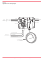
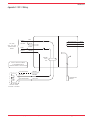
Part Number 22744 We Manage Heat ® Installation and Operation Manual Environmental Technology, Inc. 1850 N Sheridan Street South Bend, Indiana 46628 (574) 233-1202 or (800) 234-4239 FAX (574) 233-2152 or (888) 234-4238 http://www.networketi.com/ 22804 11/07 (800) 234-4239 http://www.networketi.com Environmental Technology, Inc. MANUAL Freeze Protection Thermostats MODELS SST–2 ® Model SST–2 2 of 12 Environmental Technology, Inc. http://www.networketi.com (800) 234-4239 11/07 22804 Model SST–2 Safety Make all electrical connections in compliance with the National Electric Code (NFPA 70) and local electrical code. If you have questions concerning the installation or application, contact Customer Service. Additional Information More information is regularly made available through our website, www.networketi.com. Please visit us online for datasheets, manuals, white papers, technical articles and more. The most current and up to date version of this and every other manual for our products can be found in Acrobat (pdf) format to view online or to print. This is to assist you in installing and using our products to the best effect possible. If you have any comments about this or any other material from Environmental Technology please contact us. Contacting Environmental Technology For assistance, contact Customer Service. Office hours are 8:00 AM until 5:00 PM ET. Voice: (800) 234.4239 (USA and Canada) or (574) 233.1202 (elsewhere) Fax: (888) 234.4238 (USA and Canada) or (574) 233.2152 (elsewhere) E-mail: [email protected] Mail: Environmental Technology, Inc. 1850 North Sheridan Street South Bend, IN 46628 General Description The C-UL-US listed SST–2 Freeze Protection Thermostat replaces electromechanical thermostats in cost-sensitive applications requiring ground fault equipment protection (GFEP). The SST is classified to UL and CSA safety standards by UL for use in temperature-regulation applications. It is the ideal low-cost thermostat for areas not subject to mechanical abuse. Specifications General Area of use Approvals Nonhazardous locations Type 873 Temperature Regulating Equipment 109R Enclosure Protection Cover attachment Entries NEMA 4x Polycarbonate cover, machine screws 1 × 3/4" entry (bottom right) for NEC Class 2 sensor connections 3 × 1-1/16" entries (bottom left and left) for supply, load power and (right) NEC Class 2 alarm relay connections Polycarbonate Wall mounted Material Mounting 22804 11/07 (800) 234-4239 http://www.networketi.com Environmental Technology, Inc. 3 of 12 Model SST–2 Front Panel Interface Status indicator Remote Interface Alarm relay Summary alarms Control Supply voltage Contact type Maximum Ratings Temperature Sensor Set point Dead band Sensor type Circuit type Lead Length SUPPLY (green) power applied SUPPLY (green, flashing) bad thermistor HEAT (yellow) call for heat GFEP (red) ground fault condition GFEP (red, flashing) failed GFEP test GFEP (red, flashing, rapid) GFEP test in progress Isolated SPDT 1 AMP Class 2 contact No Power Ground Fault Condition GFEP function test failure Bad or missing Thermistor 120, 208, 240 or 277 volts, single phase (automatically selected) Two Form A DPST Voltage: 277 VAC Current: 30 amps 40°F (4.4°C) 2°F (1°C) Thermistor network NEC Class 2 Up to 2,000' (610m) using 12 AWG 2-wire jacketed cable Up to 500' (152m) using 18 AWG 2-wire jacketed cable Ground Fault Equipment Protection (GFEP) Set point 30 mA Automatic self test Mode A: Verifies GFEP function before contactors operate Mode B: Verifies GFEP function every 24 hours Manual test/reset TEST/RESET switch on front panel Environmental Operating temperature Storage temperature −40°F to 130°F (−40°C to 55°C) −67°F to 167°F (−55°C to 75°C) Installation Unpacking Immediately inspect the packing material for damage. Unpack the SST–2, taking care not to damage the packaging material. Save the packaging material until normal operation has been established. If the unit must be returned, take care to ensure that it is repackaged as it was received. Packing List 22744 19272 22804 4 of 12 Environmental Technology, Inc. SST–2 Freeze Protection Thermostat Temperature Sensor SST–2 Installation and Operation Manual http://www.networketi.com (800) 234-4239 11/07 22804 Model SST–2 Initial Inspection Inspect the SST for shipping damage. If any of the following problems are found contact the Customer Service Department. • Contents incomplete or incorrect • Internal or external mechanical damage Customer service is available between 8:00 a.m. and 5:00 p.m. ET at (574) 233-1202 or (800) 234-4239. In the event of shipping damage, keep the packing materials for inspection by the carrier. Normally, Environmental Technology, Inc. will repair or replace the SST without waiting for the claims settlement. Location Housed in a NEMA 4X rated enclosure, the SST freeze protection thermostat can be mounted in either indoor or outdoor environments. The SST was designed to operate over an ambient temperature range of −40° to 136°F (−40° to 58°C). Using the integral mounting flanges, the SST is intended to be installed on a fixed, flat, vertical surface. The mounting flanges accommodate 1/4" (6mm) fasteners. The SST freeze protection thermostat nonmetallic enclosure is furnished with two 3/4" (21mm) conduit entries. The lower conduit entries provide for line voltage supply branch circuit conductors. The conduit entry at the top-left of the enclosure is for heater load branch circuit conductors. The installed weather-tight fitting is for the low voltage, NEC Class 2, temperature sensor. The Temperature Sensor may be located up to 2,000' (610m) from the SST. Supply Voltage The SST freeze protection thermostat operates from 120, 208, 240 or 277 VAC at 50/60 Hz. For line supply and load connections, use 10 AWG or larger wires rated for at least 75°C (167°F) at 300 VAC. Contactor Ratings The heater contactor provides two (2) Form A (DPST) definite purpose contacts rated for up to 30 amp AC heater loads at voltages at or below 277 VAC. 7 7/16" (189mm) 1 1/16” (27mm) Conduit Entry 4 1/4" (108mm) 1 1/16” (27mm) Conduit Entry 20' (6m) Sensor Cable, 3/16" (5mm) Ø 3/8" (10mm) Ø Temperature Sensor 1 7/16" (37mm) Figure 1: SST–2 dimensions. See Appendix A. 22804 11/07 (800) 234-4239 http://www.networketi.com Environmental Technology, Inc. 5 of 12 Model SST–2 Figure 2: SST–2 wiring. See Appendix B. Figure 3: SST–2 dimensions. See Appendix B. 6 of 12 Environmental Technology, Inc. http://www.networketi.com (800) 234-4239 11/07 22804 Model SST–2 NEC Class 2 Low Voltage Connections All low voltage wiring shall use 18 AWG or greater stranded conductors with thermoplastic insulation rated for at least 75°C (194°F) at 300 VAC. The temperature sensor is supplied with a 20' (6m) 2-wire jacketed cable lead. The temperature sensor lead may be up to 500' (152.4m) using 18 AWG 2-wire jacketed cable, or up to 2,000' (609.6m) using 12 AWG 2-wire jacketed cable. Temperature Sensor The Temperature Sensor is required for the operation of the SST. The Temperature Sensor connects via wire nuts to the two blue wires in the SST enclosure. It does not matter which sensor wire is connected to which blue wire in the enclosure. The sensor should be located near the heater being controlled and is used to monitor its temperature. Operating Instructions Power On Startup Test When power is applied to the SST–2 freeze protection thermostat, the LED indicator lights in the SST enclosure will cycle for two seconds and then turn off, except for the green SUPPLY indicator, which will remain lit whenever the SST senses supply power. Next, the SST–2 freeze protection thermostat performs a self-test of the ground fault circuitry. This is the same test automatically performed approximately every 24 hours. Failure of the ground fault circuitry self-test will disable the SST; call Customer Service. Operation The SST–2 freeze protection thermostat does not require user attention during normal operation. Status indicator SUPPLY (green) power applied SUPPLY (green, flashing) bad thermistor HEAT (yellow) call for heat GFEP (red) ground fault condition GFEP (red, flashing) failed GFEP test GFEP (red, flashing, rapid) GFEP test in progress GFEP Test To manually verify the operation of the ground fault circuitry, momentarily press the GFEP TEST/RESET switch on the SST. This should not normally be necessary as the SST will test the ground fault circuitry when power is applied to the unit and once approximately every 24 hours as long as power is supplied to the unit. GFEP Reset In the event that a ground fault condition is detected by the SST heaters will be turned off, if on, and heaters will be prevented from further operation until the ground fault condition has been reset. The red GFEP Fault indicator will be continuously on as long as there is power to the SST and a ground fault condition 22804 11/07 (800) 234-4239 http://www.networketi.com Environmental Technology, Inc. 7 of 12 Model SST–2 remains. The ground fault condition will be persistent and will be remembered by the SST even if the unit loses power. To clear the ground fault condition momentarily press the GFEP TEST/RESET switch on the SST. Maintenance The SST–2 does not require routine maintenance. For technical help, questions or comments concerning this product or any Environmental Technology, Inc. products contact the Customer Service Department between 8:00am and 5:00pm ET at: Voice: Fax: E-mail: 8 of 12 Environmental Technology, Inc. 800.234.4239 (USA and Canada) or 574.233.1202 (elsewhere) 888.234.4238 (USA and Canada) or 574.233.2152 (elsewhere) [email protected] http://www.networketi.com (800) 234-4239 11/07 22804 Model SST–2 Appendix A. SST–2 Dimensions. 7 7/16" (189mm) 1 1/16” (27mm) Conduit Entry 4 1/4" (108mm) 1 1/16” (27mm) Conduit Entry 20' (6m) Sensor Cable, 3/16" (5mm) Ø 3/8" (10mm) Ø Temperature Sensor 1 7/16" (37mm) 22804 11/07 (800) 234-4239 http://www.networketi.com Environmental Technology, Inc. 9 of 12 Model SST–2 Appendix B. SST–2 Wiring Diagram. 10 of 12 Environmental Technology, Inc. http://www.networketi.com (800) 234-4239 11/07 22804 Model SST–2 Appendix C. SST–2 Wiring. 22804 11/07 (800) 234-4239 http://www.networketi.com Environmental Technology, Inc. 11 of 12 Model SST–2 ORDERING INFORMATION Order Number 22744 19272 Description Model SST–2 Freeze Protection Thermostat Temperature Sensor (included) LIMITED WARRANTY ETI’s two year limited warranty covering defects in workmanship and materials applies. Contact Customer Service for complete warranty information. DISCLAIMER Environmental Technology, Inc. makes no representations or warranties, either expressed or implied, with respect to the contents of this publication or the products that it describes, and specifically disclaims any implied warranties of merchantability or fitness for any particular purpose. Environmental Technology, Inc. reserves the right to revise this publication, and to make changes and improvements to the products described in this publication, without the obligation of Environmental Technology, Inc. to notify any person or organization of such revisions, changes or improvements. The ETI logo, Snow Switch, Floorstat, Tracon, We Manage Heat, APS, RCU, CIT, GIT, SIT are registered trademarks of Environmental Technology, Inc. Copyright © 2006 Environmental Technology, Inc. All rights reserved. 12 of 12 Environmental Technology, Inc. http://www.networketi.com (800) 234-4239 11/07 22804