1
Operator's
Manual
]I:RRFTSMRN°I
nEXTEC
12.0 -Volt Lithium-Ion Cordless
Multi-Tool
Model No. 320.30566
c_)us
LISTED
• Warranty
Powered by an
ENERGYSTAR
qualified battery
char
• Safety
• Assembly
• Operation
• Maintenance
_lL WARNING:
To reduce
the risk of
injury, the user must read and
understand the Operator's manual
before using this product.
Sears Brands
Management
www.craftsman.com
Corporation,
Hoffman
• Espa_ol
Charge battery
before first use.
Estates,
IL 60179
U.S.A.
Ihe RurLose of safety symbols is to attract your attention to Lossible dangers.
[he safety symbols and the exLlanations with them deserve your careful
attention and understanding. The symbol warnings do not, by themselves,
eliminate any danger. The instructions and warnings they give are no substitutes
for Rro Let accident _revention measures.
Warranty
rage 2
Safety Symbols
rages 3-4
Safety Instructions
maqes 5--9
DescriLtion
aages 10-11
Assembly
aages 11-12
O meration
lages
A RRtication fools
t ages 16-28
Maintenance
Rages 29-30
Troubleshooting
aage 30
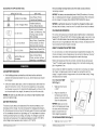
SAFETY ALERT SYMBOL: Indicates DANGER, WARNING, OR CAUTION. May
be used in conjunction with other symbots or RictograLhs.
Exaloded
Rage 31-33
,_
View and Part List
WARNING: Be sure to read and understand all safety instructions in this
manual, including al safety alert symbols such as "DANGER," "WARNING,"
and "CAUTION," before using this tool. Fai ure to following all instructions listed
below may result in electric shock, fire, and/or serious personal injury.
12-15
SYMBOL
SIGNAL MEANING
DANGER: Indicates a hazardous situation which, if not avoided, witl
result it] death or serious injury. This signal word is to be limited to the most
extreme situations.
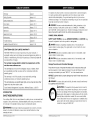
CRAFTSMAN ONE YEAR LIMITED WARRANTY
FOR ONE YEAR from the date of purchase, this power tool and, if
equipped, battery pack and charger are warranted against any defects in
material or workmanship. With proof of purchase, a defective product will
be replaced free of charge.
For warranty coverage details to obtain free replacement, visit the
web site: www.craftsman.com
_, WARNING: Indicates a hazardous situation which, if not avoided, could
result in death or serious iniury.
CAUTION: Indicates a hazardous situation which, if not avoided, could
result in minor or moderate injury.
Damage Prevention and Information
These inform the user of important
This warranty does not cover the sandpaper, rasps, or blades, which
are expendable parts that can wear otJt from normal use within the
warranty period.
Messages
information
and/or
instructions
that could
lead to ecuiLment or other iroLerty damage if they are not followed. Each
message is Lreceded by the word "NOTICE," as in the examLle below:
NOTICE: Equipment
not followed.
This warranty is void if this product is ever [_sedwhile providing
commercial services or if rented to another person.
This warranty gives you specific legal rights, and you may also have other
rights which vary from state to state.
and/or property
damage
_1_ WARNING: To ensure safety and reliability,
by a qualified service technician.
WARNING:
Sears Brands Management Corporation, Hoiiman Estates, IL 60179
The oLeration
may result if these instructions
are
all re Rairs should be _erformed
of any Lower tool can result in
foreign objects being thrown into your eyes, which cat] result
it] severe eye damage. Before beginning _ower tool o_eration,
always wear safety goggles or safety glasses with side shields
and a full-face shield when needed. We recommend a Wide
INTRODUCTION
SAVE THESE INSTRUCTIONS
Vision Safety Mask for use over eyeglasses or standard safety
glasses with side shields. Always use eye Lrotection which is
marked to com|ly with ANSI Z871
This cordless Multi-Tool has many features for making its use more ileasant and
enjoyable. Safety, _erformance, and de Lendability have beer] given to L iriority
in the design of this Lroduct making it easy to rnaintain and oLerate.
_, WARNING: Some dust created by using Lower tools contains chemicals
known to the state of California to cause cancer and birth defects or other
re Lrod uctive harm.
30566 ManuaLRev sed !1 0715
Pase 2
30566 Manual
Revised 11 0715
Pase 3
SAVE
THESE
INSTRUCTIONS
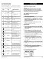
Some of these following symbols may be used on this tool. Please study them
and learn their meaning. Pro_er interlretation
of these symboHs will allow you to
omerate the tool better and more safely.
SYMBOL
NAME
Volts
Voltage
A
Am 0eres
Current
,_
WARNING: Read and understand all instructions. Failure to follow al
instructions listed below may resuR in electric shock, fire, andTor serious
aersonal iqiury. The term "mower tool" in all of warnings listed below refers to
corded tower tools or battery-oaerated (cordless) aower tools.
DESIGNATION/EXPLANATION
V
GENERAL POWER TOOL SAFETY WARNINGS
Save all warnings and instructions for future reference.
Hz
Hertz
Frecuency (cycles t er second)
W
Wait
Power
rain
Minutes
Direct
rio
Current
Class
_./min
Rotational
II Construct
on
PerMinute
Wet Cond}t
•
Do not operate power tools in explosive environments,
such as in the
presence of flammable
liquids, gases, or dust. Power tools create smarks,
which may i_nite the dust or fumes
°
Keep children and bystanders
away while operating
Distractions may c;_use you to lose control
Double-
of current
steed,
at no load
nsulated
coustruct}on
ELECTRICAL
Revolutions,strokes, surface seeed,
orbits, etc., ter minute
ons Alert
Read The O_erator's
Keep your work area clean and well lit, Cluttered or dark areas invite accidents
TyJeof current
Type or a characteristic
No Load Steed
]
•
Time
AlternatingCurrent
--'_
WORK AREA SAFETY
Manna_
local
Do notons.
extose
a power tool.
SAFETY
°
Avoid body contact with grounded surfaces, such as pipes, radiators,
ranges, and refrigerators. There is an increased risk of electric shock if your
body is grounded.
°
Power tool plugs must match the outlet. Never modify the plug in
any way. Do not use any adaptor plugs with grounded power tools.
Unmodified plugs and matching outlets will reduce the risk of electric shock.
to rain or use n damt
read
and undersl
o leratoffs
To reduce
the risk :rod
of kLinry,
user manual
must
before using th}s troduct.
Eye Protectiou
O
A
Safety Alert
No Hands Sylnbol
ManuaLRev
a
Fa lure will
Node
to keel
resultyour
in serious
hands lersona_
away fromnjury.
the
No Hands
Symbol
Fa lure to keew your hands away from Lhe
b_lde w}lt result in serious tersonaW njury,
No Hands
Sylnbol
Fa lure to keee your hands away from the
blude w}Hresult in serious _ersona_ }njury.
110715
Water entering
Do not abuse the cord. Never use the cord for carrying, pulling, or
unplugging the power tool. Keep the cord away from heat, oil, sharp
edge, or moving parts. Damaged or entangled cords increase the risk of
electric shock.
Precautionsthat involve your safety.
Fa lure teI keet your hands away from the
Uade wH result iu serious Imersonal }njury,
Hot Surface
sed
glasses
with side
andorasafety
full flee
Always wear
safety shields
goggles
shield when ote[ tt ng th}s eroducL
No Hands SynlbOl
®
30566
Do not expose power tools to rain or wet conditions,
cower tool witl increase the risk of electric shock.
To reduce the risk of iniury or damage,
avoid contact wth any hot surface.
Page 4
When operating a power tool outdoors, use an extension
cord suitable
for outdoor use. Use of a cord suitable for outdoor use reduces the risk of
electric shock.
If operating a power tool in a damp location is unavoidable, use a
ground fault circuit interrupter (GFCI} protected supply. Use of a GFCI
reduces the risk of electric shock.
•
Use only the battery
arid with the chargers listed:
BATTERY PACK
CHARGERS
320,1!22!
320,14300
32029497
320,10006
30566 Manual_Revised_:!l
0715
Page 5
PERSONAL SAFETY
Keep cutting tools sharp and clean, Pro=edy maintained cutting tools with
shar= cutting edges are less likely to bind and are easier to contro!_
Stay alert, watch what you are doing and use common sense when
operating a power tool. Do not use a power tool while tired or under the
influence of drugs, alcohol, or medication. A moment of hlattention while
olerating lower rooks may resuDtin serious iersonal hljury.
•
Use personal protective equipment. Always wear eye protection. Safety
ecuilment, such as dust mask, non-skid safety shoes, hard hat, and hearing
irotection, when used for al irotriate conditions, witl reduce mersonaliniuries.
•
Prevent unintentional starting. Ensure that the switch is in the OFFposition before connecting to a power source and/or battery, picking up
or carrying the tool. Carrying power tools with your finger on the switch or
energizing =ower tools that have the switch on invites accidents
•
Remove any adjusting key or wrench before turning the power tool on. A
wrench or key left attached to a rotating =art of the =ower tool may result in
=ersonal iqiury,
•
Use the power tool, accessories, blades, etc. in accordance with these
instructions and in the manner intended for the particular type of
power tool, taking into account the working conditions and the work
to be performed. Use of the =ower tool for o=erations different from those
intended could result in a hazardous situation,
BATTERY
Make sure that the switch is in the OFF =osition before inserting the battery
=ack. Inserting the battery =ack into =ower tools that have the switch QN
invites accidents,
°
*
If devices are provided for the connection of dust extraction and
collection facilities, make sure that these are connected and properly
used. Use of these devices carl reduce dust-related hazards.
•
30566
Use power tools only with specifically
designated
battery
any other battery packs may create a risk of injury and fire.
packs.
Use of
Under abusive conditions, liquid may be ejected from the battery;
void contact. If contact accidentally occurs, flush with water. If liquid
contacts eyes, additionally seek medical help. Licuid ejected from the
battery may cause irritation or-burns.
POWER TOOL USE AND CARE
•
lack,
When the battery pack is not in use, keep it away from other metal
objects, such as paper clips, coins, keys, nails, screws, or other small
metal objects that can make a connection from one terminal to another.
Shorting the battery terminals together may cause bums or a fire.
Dress properly. Do not wear loose clothing or jewelry. Keep your hair,
clothing, and gloves away from moving parts. Loose clothes,jewelry, or
long hair can be caught in moving =arts.
•
Recharge only with the charger specified in this manual. A charger that is
suitable for one type of battery pack may create a risk of fire when used with
another battery
Do not overreach. Keep proper footing and balance at all times. This
enables better control of the tower tool in unex=ected situations.
Do not force the power tool. Use the correct power tool for your
application.
The correct =ower tool will do the job better and more safely at
the rate for which it was designated.
TOOL USE AND CARE
SERVICE
•
Have your power tool serviced
identical replacement
tool is maintained.
by a qualified
repair person using only
parts. This wifl ensure that the safety of the =ower
Do not use the power tool if the switch does not turn it ON and OFF. Any
=ower tool that cannot be controlled with the switch is dangerous and must
be re=aired.
•
Disconnect the plug from the power source and/or the battery pack
from the power tool before making any adjustments, changing
accessories, or storing power tools. Such treventive safety rneasures
reduce the risk of starting the tower tool accidentally.
SPECIFIC SAFETY RULES FOR CORDLESS MULTI-TOOL
*
Store idle power tools out of the reach of children and do not allow
persons unfamiliar with the power tool or these instructions to operate
the power tool. Power tools are dangerous in the hands of untrained users
Never use your Multi-Tool to =erform sanding or se=arating o=erations in
wet conditions.
o
Always wear eye =rotectiorl.
o
Always wear ear =rotection during extended ieriods of o=eration,
o
Always wear a dust mask if the o=eration is dusty,
*
Wear irotective gloves when changing a1 ilication accessories. A=|lication
accessories become hot after mrolon,qedusage.
Maintain power tools. Check for misalignment or binding of moving
parts, breakage of parts and any other condition that may affect the
power tool's operation. If damaged, have the power tool repaired before
use. Many accidents are caused by =oorly maintained =ower tools.
ManuaLRev
sed
:!1 0715
Page 6
Follow instructions in the Maintenance section of this manual. Use of
unauthorized ia_s or failure to follow Maintenance instructions may create a
risk of shock or injury.
30566
ManuaLRev
sed_11
0715
Page 7
Im]__o_l
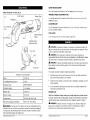
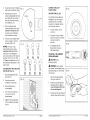
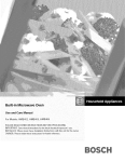
KNOW YOUR MULTI-TOOL
QUICK=RELEASE L_#ER
The cuick°release #evera#ows for toobless a _ication
(Fig.l)
tool exchange.
VARIABLE-SPEED ADJUSTMENT DIAL
Fig. 1
Battery
On/Off Swkch
Ihe variable°sleed
a i i_rolriate
s teed
FuelGal_ge
dial is located on the left side of your tool for select ng the
LED WORKLIGHT
Quick-Release
lever
fhe LED worklight is located in the front of the tool. This feature, rovides extra
light for increased visibility.
FUELGAUGE
Battery- Release
lED Worklight
Vents
lhe FuelGauge indicates the battery-iack
\
Button
Variable°S i_eed
Adjt_stment Dial
__
charge level.
_, WARNING: ff any taAs are broken or missing, do not attem |t to attach the
battery or oeerate the tool until the broken or missing tarts arc re_laced. Failure
to do so could result in iossible serious injury.
Drive Shaft:
WARNING: Do not attem i,t to modify tills tool or use accessories not
recommended for use w_ththis tool Any such alteration or modification is misuse
and could result in a hazardous condition leading to mossibly serious injury.
,_ WARNING: To trevent ac:c:identalstarting that col_ld cat_se seriol_s lersonal
injl;ry, always remove the battery _ack from the tool when assembling _arts.
UNPACKING
This product has been shimi;ed com|letely assembled
PRODUCT SEPCIFICAIION
•
Carefully remove the tool and accessories from the box. Make sure that a#
items listed in the macking list are included.
•
Instect the too_ carefully to make slse that no breakage or damage occurred
during shi e _ing.
•
Do not discard the lacking matedal until you have carefully inspected and
satisfactorily olerated the tool.
Motor
12 Volt DC
Too! Weight (without battery)
1.8 Ibs
Oscillation Rate
7500ol 5000/rain
Oscillation Angle
±1.4 degrees
Battery Tyie
Lithh_mqon
PACKING LIST
Battery Vokage
12 Volt DC
Charger Inlut
120-Volts, 60 Hz AC only
O m,timtimCharging Temwerature
32°F (0° C) -104°F (40°C)
Multi-Tool, QuickBoost charger, battery pack, straight edge flush cut b_ade,circular
s_ blade, hardened steel scra ling blade, carbide circular ad hesive removal blade,
carbide triangular ras_, _nding _late and 9 i,cs s_andia_er, o_,erator's manual.
WARNING: The safe use of this m,
roduct recuires an understanding of the
information on the tool and in this oD,erator's man_al, as well as knowledge of
the irojec:t you are attem i0ng. Before iising this iroduct, familiarize yourse#f
with all oierating features and safety roles
30566 MaouaLRe_ sed :1J.-O71,5
_ge 10
_, WARNING: ff any _aA is broken or missing, do not attemJt to _,lug in the
mower cord or olerate the tool until the broken or missing _art is re=laced..
Failure to do so could result in i:ossible serious injury.
30566 MaouaLRev_sed l_,07ff5
Page 2&
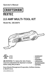
SELECTING THE APPLICATION TOOL
APPUCA1 ION ]COL
L._
i_C_)
.I
°
°
_!'
_e LED worklight wiHIbegin flash sRowlyif the batte_ circuit@ detects a
momentary overload.
MATERIALS
Carbide Circular Blade
Grout,
Plaster,
Porous
Concrete
and Masonry
NOTICE: The batte@ can automatically reset, if the LED continues to flash rapidly, it is indicating that the charge is substantially diminished. Place the battery
into the charger for charging. (See LOW BATTERY INDICATOR, above.)
Carbide Triangular Rasl
Hardened
adhesives,
Thinset,
Wood,
Masonry
NOTICE: A signfficanUy reduced run time after fully charging the battery pack
indicates that [he battery is near the end of its usable life and must be re i,laced.
Paint & Varnish° Bonded
COLD WEATHER
Scra _er Blade
Carl, et, Soft
Adhesives°
Flooring,
wood
and otherVinyl
floor coverings.
Circu6ar Saw Blade
Wood,
FerrousPlastic,
Metals,D_atl,
thin Sheet
Non°
Metal and other materials
F.osh
CutU..de
Wood,
P,astOry'wa,
c, soft
Metals and other materials
Sanding
Sandiai,erPlate and
Bare
or Painted
Wood,
Plaster,
and other
surfaces,
detending on sandpaper grit
LOW-BATTERY INDICATOR
ff the FuelGauge shines red when the on/off switch on the mu_ti-tool is
activated, the battery lack a:owerhas run out, and the battery I:ack should
be recharged.
Unlike other battery.. _>acktyros, Lithiumqon battery tacks deliver fadeofree
D,owerfor their entire run time. The tool will not exierience a slow, gradual
loss of wower as you work. To signal that the battery iack is at the end of its
run time and needs to be charged, the mowerto the tool will drol cuickly.
NOTICE; The LED may also flash due to an overMoad or high temperature
BATTERY PROTECTION},
BATTERY
This Lithiumqon battery tack will u,rovide o|timal _erformance in tern _eratures
between 32°F (0°C} and 104°F (40°C). When the batte_ eack is very cold, it may
"pumse"for the first minute of use to warm itseffo Put the batte_ pack on a tool
and use the tool in a light at ttication. After about a minute, the batter_ mackwill
have warmed itself and will o lerate normally.
WHEN TO CHARGE THE BATTERY PACK
It is not necessary to run down the battery lack charge before recharging, The
Lithiumolon battery can be charged at any time and will not develoi a "memo_"
that reduces total charge when recharged after a t,artiat discharge,
Remove the battery i:ack from the tool when convenient for you and yourjob.
"1eL off" the battery tack charge by charging it for a time before starting a big
job or long t:,eriodof use.
Due to Lithium-ion fade4ree irolerties, the only time it is necessary to charge
the Lithium- _on battery tack is when the _ack has reached the end d its
charge. To signal the end of charge, mower to the tool will dro_ ouickly. Charge
the battery _ack as needed.
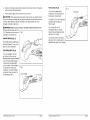
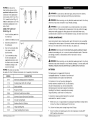
TO ATTACH BATTERY
PACK (Fig. 2)
1.
Make sure that the tool
is "OFFJ'
2.
Align the raised ribs on
the battery _ack with the
grooves in the tool, and then
attach the battery Hack.
(see
PROTECTION
The battery circuitry i:rotects the battery lack from extreme tern _erature, over°
discharge, and over-charge To trotect the battery from damage and irolong its
life, the battery aack circuitry will turn off the battery _.ackif it becomes overloaded
or if the tern terature becomes too high during use. This may ha t i)en in situations
involving extremely high torcue, binding, and stalling. This intelHgen[system will
shut down your battery lack if its oterating tem|erature exceeds 176"F (80°C}
and will begin normal o_eration when it returns to 122°F (50°C).
30566 Ma#uaLR_
sedj.10715
Pa_ 12
OPERATION
Fig, 2
NOTICE: Make sure that the
latch on the batte_ _ack sna_s
into _lace and that the battery
_ack is secured to the toot
before beginning o_eration.
TO DETACH BATTERY PACK (Fig. 2)
1,
Make sure that the tool is "OFF."
30566 Mar_uaLRev_sed 1:_ O715
Page _3
2.
3.
Detress the batteryorelease buttons located on the both sides of the battery
lack to release the battery lack.
Pull the battery ,ack out and remove it from the tool.
CAUTION: When mlacing the battery _ack in the tool, be sure that the raised
ribs on the batterv lack align with the grooves inside the tool and that the latches
snare into tlace Iroeerly_ Im_roter assembly of the batte_ eack can cause
damage to internal comeonents_
WARNING: Battery-tools are alw_s in operating cond_ion; therefore, the on/
off switch should always be in the
"OFF" nostion when not in use or
carrying the tool at your side.
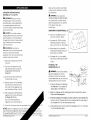
ON/OFF
SWITCH
Fig. 3
FUELGAUGE
(Fig. 5)
This too_ is ecniloed
Fig. 5
wKh a
FueIGauge, which indicates
battery° tack charge level
FuelOauge
the
The green LED on the FuelGauge
indicates that the battery is
fully charged.
The o[ange LED on the
FuelGauge indicates that the
batte[y I_as used a| |roximately
one half of its charge.
The red LED on the FuelGauge
indicates that the battery _ack is
deileted and needs to be charged,
(Fig. 3)
To turn the tool on, push the on!
off switch fo_ard. To turn it off,
eush the switcrl backward
LED WORKLIGHT (Fig, 4}
The LED worHight, located
on the front of the tool, will
illuminate when the on/off switch
is in the forward (ON} iosition.
This irovides additional light
on the surface of the worktiece
for omeration in lower-light
conditions° -[he LED worMight
wil_turn off when the switch is
slid backwards (OFF}.
30566 M_muaLRe_Jsed=J,&©71,.5
Fig° 4
LED worMight
_,...
Page _4,
30566 Manual Rev sed lt_ 491:_5
Pa_ 25
_ "a".1I_o]E1iil[o]tll[_o_
blade, and the carbide circula_ blade
should never be attached so that the}/
face backwards.
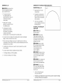
ATTACHING THE APPL|CATIOfL
IOQS {Figs, 6, 7, 8, 9 and 10)
_l
_i, WARNING: Do not attach the
circular saw blade, the flush cut b_ade,
the scrater blade or carbide circular
blade facing backwards, as o|eration
in this tosition may cause
serious irgut:y.
WARN|NG:LFaikJre to removeL
the battery wack from the tool whenL
assemblinq _art:s, making adiustments,
or changing aHlication tools could
result in accidental startinq and _ossibly
cause serious iqu_
_L
SANDPA_R KIT DE_RI_ION
OAUTIOf: For all work or when_
changing
a _1t)cation
tools,
always
• L9 _ieces of sandma_>er:3lieces
each of 60_ 120 and 180 grit.
wear
_;rotective[.gloves_ The sharm edges of
the aHlication tools will cause _emonal
injury. A_ ilication tools can become
ve_ hot during use_
• LSand_a_er Kit 67655 (available
separately} includes 24 _ieces: 8
_ieces each of 60, 120 and 180 qriL
AI_,LWARNING:LCheck that the
• LAIways aHly to the corn _atible
sanding _late (su _Iied with yourL
Nextec Multi to@ 3056@
a H_ication tools are correctl7 attached.
Incorrect or insecurely fastenedL
a m_Ucation tools can come loose during
o_eration and cause a hazard,
* LSand_a_er kit is also compatible
with the Bosch PMF180E and GOP
1. LRemoveLthe battery tack f_om the
multi-tool.
.
10.8V-Li.
TO iNSTALL THE
SANDPAPER {Fig. 12)
LPush the o uickorelease lever fully
om_enwith 7our _alm to loosen the
flange bo_.(Figo 6) Remove the
flange bo_o
_1_ WARNING: Check that the s_ndin[_
_late and sand _a_er are cor_ectl7
attached. £_ incodect or
faslened a_lication tool can come loose
during o_eration and cause a hazard
3. LEnsure that the inner threads and
the driveLshaft are clean.
4_
5_
LAlign the grooves on the a| _lication
tool with the tour raised ribs on the
drive sha_. Put the a| _lication tool
onto the ddveLshaf{ (f igs. 7 and 8}.
LFoIIowthe di[ections for AEaching
the A||lication Tool to attach the
sanding _late to the MultioTool.
2_
I With yourLgloved hand holding the
a_ _iication tool insert and de_ress
the flange bolt until you
hear a click indicating that the
aiwlication tool is secured (Fig. 9)..
6_ I,Press the cuickorelease
lever with yourL_.alm
NOTICEs Attach the aHlication
tool in the desired
hand. The shaft is configured so that
45 ° around the shaft, from 0 ° to 315 °,
30566 Ma_uaLRe,_ sed $£ 071,5
(_g, 11)
3_
to lock:
10).
_tskat
Lched every
the scraper
Page _.6
_lign the sandpaper with the sanding _late and use yourLhand to _ress it
firmly onto the sanding plate.
LPress the sandpaper firmly against a smooth sudace for a short period, then
switch on the tool. -[he burr will form a nonosli| bond with the outer edge of
the sandpaper fell This will avoid _remature wear_.
4, Lff one _ointLhas become worn, _ull off the sand ia _er, turn it 120 ° and _lace
it on the sanding _late again.
30566 Ma_suaLRev sed £_@7t5
Pa£e 17
SANDING
_,
SAWING WITH THE CIRCULAR SAW BLADE (67651)
(Fig, 13}
WARNING:
DESCRIPTION (Fig. 14)
Do not touch the
motor housing after mrolonged
use; it could be very hot.
High steed steel circular
cutting blade.
The rernovaBrate and
the sanding ,attern are
determined by the choice of
sanding sheet and the
work surface.
Designed for cuWng wood,
t lastic, drywall, non-ferrous
metals, thin sheet metal and
other materials.
•
A_ tly uniform sanding
eressure to extend the Bifeof
the sanding sheets.
TO INSTALL THE CIRCULAR
SAW BLADE
Intensifying the sanding
iressure does not head to
_i,
an increase of the sanding
calacity,
but instead it
increases wear on the machine and the sanding
sanding
1.
For Rough sanding
2.
For Srnooth sanding
sanding accessories
of
damaged
can break.
_L, WARNING:
When sawing
light building materials, observe
the mrecautions and the
recommendations
of the
rnaterial su i ,liers.
67655,
_IL WARNING:
use 40-80 grit tater.
use 120-180
Use shaft,
undamaged saw blades only.
Deformed, blunt saw blades or
saw blades that are otherwise
A sanding sheet that has been used for metal should not be used for
other materials.
Craftsman
Wear
gloves.
WARNING:
sheet,
When selectively sanding on one s,ot, the sanding sheet can heat uR
considerably.
Remove the tooD from the surface teriodically
to ,ermit the
sanding sheet to cool down.
Use only original
CAUTION:
t rotective
Use onUy the til or an edge of the sanding sheet for irecise
edges, corners and hard to reach areas.
•
The circular saw blade is
also comlatible
with the Fein
Multi-Master
tool.
Plunge cuts may
only be al ilied to soft materials,
such as wood, gymsum ilaster
boards, etc.
grit.
_h, WARNING:
The sawing teeth
are very sharm. Do not touch
during mounting and al mlication.
WARNING:
Do not attach
the circular cutting blade facing
backwards (Fig.15}, which may
hurt the user.
30566 ManuaLRev sed
!:_ 07;15
Pap=e&8
1.
Remove the battery lack
from your multi-tool.
2_
Push the quick-release
bolto (Fig° 16) Remove
30566 ManuaLRevsed
:11 0715
lever fufly open with your palm to loosen the flange
the flange bolt.
Pap=e19
Ensure that the inner threads
and the drive shaft are clean
3_
CARBIDE CIRCULAR
BLADE (67650}
Fig, 17
Align the grooves on the
circular cutting blade with the
four raised ribs on the drive
shaft; Jut the blade onto the
drive sha& (Fig, 17)°
4_
.
DESCRIPTION
With your gloved hand
holding the blade, insert and
depress the flange bo_ until
Press the ouickoreiease lever
with your ialm to lock the
driver shaft (Fig 10)o
2.
Draw cutting lines on
the work miece.
4
Turn on the tool and allow
it to come to the ful_
desired s_eed
5_
j
Compatible with the
Nextec Multi,oTool and
Fein MultioMaster.
TO INSTALL THE CARBIDE
CIRCULAR BLADE
,_
CAUTION: Wear
irotective gloves.
WARNING: Do not attach
the carbide circular blade facing
backwards (Fig° 21), which may
hurt the user.
#]serLthe battery lack into
the multi°tooL
&
,
Fig.21
F_g.18
WITH THE CIRCULAR
Securely damt the
workeiece if necessary_
,;,,\.
Designed for grout, i[aster,
masonry or iorous concrete
removal around the
wall tiles.
SAW BLADE (Fig. 19)
1.
x\
Carbide.otiHed, circular
grout disc..
NOTICE: The ribs on the
shaft and the groovesinthe
application too_s permit a firm
connection of the a_ilication
tools in increments of 45 ° around
the shaft from 0 ° to 315 ° (Fig°
18)oAi_ly the aii_ication tool in
the orientation aHroiriate to the
task at hand.
CUTTING
(Fig. 20}
The Carbide Circular Blade is
designed to cut out the grout
around wall tiles, it can also
be used to cut tlaster, _orous
concrete and masonry°
you hear a click indicating
that the blade is secured,
6,
Fig. 20
1.
Remove the battery lack
from your multi-.tooi.
2_
Push the cuickorelease lever
fully oten with your e,almto
_oosen the flange bolt (Fig, 22)°
Remove the flaqge be&
Fig 1
3_
Fig. 22
Ensure that the inner threads
and the drive shaft are dean..
Attly the the cutting blade
to the work_iece and make
the cut.
30566 MaauaLRe_ised_:t&O?'lo5
Pa_ 20
30566 ManuaLRevised
J I 07!5
Page 21
4.. Align the grooves on the
circular grout disc with the
four rai_d ribs on the drive
shaft; sut the at ilication tool
onto the drive shaft (Fig. 23)_
SCRAPER
Fig, 23
DESCRIPTION
Scra|er blade is also
com|atible
with the Fein
Mu ItioMaster tool.
6_ Pressthe ouick°re_ease lever
with your palm to mockthe
driver shaft (Fig. 10)o
TO INSTALL THE
SCRAPER BLADE
F_g. 24
Insertthe battery ,ack inLo
the multi-tool.
2
Draw the cutting lines on
the work siece.
3_
4.
5.
Turn on the tool and altow
it to come to the full
desired sieed.
_,
Fig°27
WARNING: Do not attach
the scraper blade f_cing
backwards (Fig 27), which may
hurt the user.
,[,:
Fig° 28
D
WARNING: Check that
the a | |licadon tool is correctly
attached. Incorrect or insecurely
fastened a i.tlication tool can
come loose during oleration and
cause a hazard.
F_g. 25
Place the carbide circular
blade against the work tiece
at a 90 ° angle.
,
Cut out the grout around
the tile, then use a hand
chisel to remove the tile
from the wall.
,
NOTICE: When cutting grout,
masonry and iorous cement,
take into consideration that the
appnication teems/accessories
wear heavily when used for longer ieriods of time.
30566 Ma_uaLRe'_ sod 11-O715
CAUTION: For all work
or when changing amilication
tool, a_wayswear trotective
gloves. The share edges of
the a s|lication tool will cause
_ersonal in}uryoAmslication tool
can be very hot while working.
(®)
CU_ING GROUT WITH
THE CARBIDE CIRCULAR
BLADE (Fig, 24}
1.
Fig. 26
(Fig. 26)
Steel scrasing blade
designed for saint &
varnish, bonded cariet, soft
adhesives, vinyl flooring,
wood and other
floor coverings.
5,. With your gloved hand holding
the blade, insert and dem_ress
the range bert unti_you hear a
click indicating that the circular
grout di_ is secured.
NOTICE; The ribs o_r_
the
shaft and the grooves in the
application tools permit a firm
conr_ection of the a wmlicadon
tools in increments of 45 ° around
the shalL, from 0° to 315 ° (Fig.
24). Aiily the aH_ication tool in
the orientat ion a _ ere wriate to the
task at hand.
BLADE (67652)
3.
Page 22
Remove the battery sack
from your mu_tiotOOl.
Push the (-uick-re[ea_ lever
fully o|en with your talm to
loosen the flange bo_t(Fig°
28). Remove the flange bo_to
Ensure that the inner threads
30566 ManuaLRev sod 1I 0715
and the drive shaft are clean.
Page 23
4_
5_
6,
CARBIDE TRIANGULAR RASP (67654)
Align the grooves on the
scraler blade with the four
raised ribs on the drive shaft;
_ut the scraiJer blade onto
the drive shaR (Fig. 29),
DESCRIPTION (Fig. 32)
Carbide tilled
grout ras_.
With your gloved hand
holding the blade, insert and
depress the flange bolt until
Designed for grout, masonry,
thinset, wood and removal of
hardened adhesives on the
wall tiles.
you hear a crick indicating
that the scra let blade
is secured
t
Push the cuickorelease _ever
with your talm to lock the
driver shaft (Fig. 10),
TO INSTALL THE CARBIDE
TRIANGULAR
RASP
NOTICE:
The ribs on the
shaft and the grooves in the
appRication too_s permit a firm
connection of the aHlication
tools in increments of 45 '° around
CAUTION:
rotective
,
2_
USING THE SCRAPER
BLADE (Fig. 31)
2.
h_sertthe battery
the multi-tooL
Triangular ras_ is also
commatib0e with the Fein
Mu Iti_Master tool.
Fig. 30
the shaft, from 0° to 315°(Fig
30)° Amply the aii_ cation tool in
the orientation aH, romriate to the
task at hand.
1.
triangular
3_
tack
gloves,
Remove the battery mack
from your multiotool.
Push the cuick-release lever
fully o0en with your ialm to
Roan the range bolt (Fig, 33)o
Remove the flange bo_o
Ensure that the inner threads
and the drive shaft are dean°
into
4_
Turn on the tool and allow
it to come to the full
desired sleed.
To scra_;e, _,ut the tool on
the workpiece at a flat
5_
angle (not more than 20°},
and aHly onUy light
iressure so as to not cut
into the surface
6.
To cut and remove carwet,
_lace the Scrater Blade
vertically on the worktiece,
and cut the cariet. Then
i_ace the scraler blade
between the cariet and the
floor to the coverings and adhesive
30566 Ma#ual Re,_ised_$_ 0T1.5
Wear
Align the grooves on the
carbide triangular rasi with
the four rai_d ribs on the
drive sha_; m,utthe rasm onto
the drive shaft (Fig, 34},
With your gloved hand
holding the blade, insert and
depress the flange bolt until
you hear a click indicating
that the rasw is secured
Push the cuick-release lever
with your maimto lock the
driver shaft (Fig. 10}..
residue off.
Pag÷ 24
30566 M÷nuaLRevised
llZ)f15
Pa_ 25
NOTICE: The ribs on the
shaft and the grooves in the
appmicationtoo_s permit a firm
connection of tile accessory
tools in increments of 45 °, from
0 " to 315 ° around the shaft (Fig.
35). Attly the al J[ication tool in
the orientation atlroeriate to the
task at hand.
TO INSTALL THE FLUSH CUT BLADE
Fig. 35
,_
WARNING: Do not attach
U
the flushocut b_adefacing
backwards (Fig. 38}0which may
hurl the user.
Remove the battery eack
from your mu[tiotool.
USING THE CARBIDE
TRIANGLUAR RASP {Fig. 36)
Push the cuick-re[ease
2_
Draw the cutting lines on the
work liece.
,
Turn on the tool and allow
it to, come to the full
desired sleed.
4_
5_
4_
Put the rasp flat against
the workliece and a 101y
a i lro t:riate lressure.
5_
Remove any hardened
adhesive or grout on the
surface of the wall tiles.
FLUSH CUT BLADE (67653)
DESCRI_ION
Bi-rmetal,
(Fig. 37)
straight-edge0
[c_or
fully oten with your talm to
Boosen the f_nge bolt (Fig° 39),
Remove the flange bo_o
hlsert tile battery lack into
the multi-tool.
2.
CAUTION; Wear irotective gloves.
6_
flush-
cut blade
Ensure that the inner threads
and the drive sha_ are clean.
Align the grooves on the
flushocut blade with the four
raised ribs on the drive shaft;
l:ut the a l llication too[ onto
the drive shaft (Fig. 40).
With your gloved hand
holding the blade, insert and
depress the flange bolt until
you hear a click indicating
that the flush cut blade
is secured.
Push the cuick-release _ever
with your lalm to _ock the
driver shaft (Fig..10}_
Designed for cutting wood,
ilastic, drywall, soft meta_
and other materials.
Can 1Hungeand saw with a
slight lenduk_m action
in wood.
Flush Cut blade is also
corn_atible with the Fein
MultioMaster tool_
30566 Ma_uaLRe_ised_:l,_,O71,5
Ps_ 26
30566 Manual ,"4evsed 1I 0715
Page,27
NOTICE:The ribs on the
shaft and the grooves in the
application tools permit a firm
connection of the aitiication
in increments of 30 °, from 0_ to
315 ° around the shaft (Fig. 41).
Allly the at tlication tool in the
orientation a m_ro eriate to the
task at hand.
Fig. 41
,_ WARNING.'.To avoid serious _ersonal injup_*,always remove the battery
i_ack from the tool when cleaning or lerforming any maintenance.
_lk WAFINING: When servicing, use only identical reilacement
other marts may create a hazard or cause iroduct damage.
,_ WARNING," _tis not recommended to use co,mtressed dry air as cleaning
method of the tool If cleaning with corn i,ressed air is the only method to a_ _ly,
always wear safety goggles or safety glasses with side shields when using
compressed air to clean the tool if the o_eration is dusty, also wear a dust mask.
USING THE FLUSH CUT
BLADE (Fig. 42)
1.
Rnsertthe battery tack into
the multi-tool.
2.
Ctaml theworkiiece
3
Draw the cutting
the work: i, iece_
4.
Turn on the tool and allow
it to come to the full
desired smeed.
5,
GENERAL MAINTENANCE
securely.
lines on
Avoid using solvents when cleaning ilastic ma_s Most _lastics are suscettible
to damage from various tyles of commercial solvents and may be damaged by
their use. Use clean c:loths to remove dir_, dust, oil, grease, etc.
Fig, 42
WAFIN|NG; Do not at any time _etbrake fluids, gasoline, petroBeumobased
|roducts0 |enetrating oils, etc. to come in contact with _lastic tarts. Chemicals
can damage° weaken or destroy _iastic which may result in serious
_ersonal ir_uryo
Cut the work tiece along
the line and a_ly with
aw _ro,ariate tressure until
the blade cuts to the de_th
WARNING; When servicing, use only identic:al reilacement ia_s. Use of any
other _a_ts may create a hazard or cause _,roduct damage. To ensure safety and
reliability, all repairs should be performed by a qualified sewice technician.
needed according to the
scale on the blade.
NOTICE:
BATTERIES:
The multi_,tool can also
be used with other Craftsman
accessories
(sold se narate!y} listed below:
MODEL
The battery _ack is eoui_ed with Lithiumoion
rechargeable batteries The duration of u_ from each
charge will de _,endon the type of work i,erformedo
DESCRIPTION
30753
MultiotOOIsanding _late for reilacement
17374
Sanding Pale_ (220, 280, 320 grit)
17375
Betait cut blade
17376
Rough cut btade
30858
Multi-tool Caulk Removal btade
31021
Diamond Coated Semicircle Saw Blade
31020
Circular Cutting Blade
3102
Stainless Steel Felt Polisher
31022
Finger Sanding Pad
31023
Finger Sanding Sheet Coarse
30566 I_a_uaLRe_ sed ']J O7!,.5
i:ar[s. Use of any
The batteries in this tool have been designed to
_rovide maximum trouble-free life. Like all batteries,
they will eventually wear out. Do not disassemble
the battery _ac:kor attempt to re_lace the batteries.
Handling of the batteries, es_,ecial_ when wearing
rings and jewelry, could result in a serious bum.
To obtain the longest _ossible battery life, read and
understand the o_erator's manual.
When not in use, it is good _,rac:ticeto un|lug the QuickBoost charger and to
remove the Lithium ion battery _ack f_om the tool.
For Lithium.Jon battery _ack storage longer than 30 days:
•
Page 28
Store the Lithium-Ion battery _ack where the tern _erature is below 80°F
(26°0} and Freeof moisture.
30566 ManuaLRe,,_ sedoJ,_ 071,.5
Pa_e 29
•
Store Lithiumqon battery lacks in a 30%-50% charged condiLion_
•
Every six months of sLorage, fully charge the Lithiumqon battery lack.
•
Exterior may be cleaned with a cloth or soft nonometaHic brush
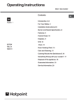
I".,_I1t!1_LId"JIll
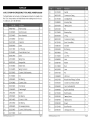
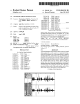
12 VOLT LITHIUM-ION CORDLESS MULTI-TOOL MODEL NUMBER 320,30566
The Model Number will be round on the Name wlate attached to the handle of the
MultioTool. Always mention the Model Number when ordering Áarts for this toolo
To order iarts, call 1o800o469o4663o
BATTERY PACK REMOVAL AND PREPARATION FOR RECYCLING
To i,reserve natural resources, ilease recycle or disiose of batteries _roierly,
This lroduct contains lithium...ion batteries. Locan, date, or federaJ laws may
_rohibit diseosal of lithium-ion batteries in ordinary trash_ Consult your local waste
authority for information regarding availabMe recycDing and/or disposal options.
\
WARNING" Uion removal of the battery lack for dislosal oFrecycling,
cover the battery iack's terminals with heavyoduty adhesive tale. Do
not attem it to destroy or disassemble battery lack or remove any of its
comtonents. Lithiumqon batteries must be recycled or dis!osed of iroierly..
A_so, never touch both terminals with metal objects and!or body parts as
short circuit may rosuit. Keel away from children. Failure to corn _ly with these
warnings could resumtin fire and/or serious injury.
\\
PROBLEM
CAUSE
The tool does not work
Battery is de _:.leted
Motor overheating
Be sure cooling vents
are free from dust and
obstacles
/
SOLUTION
Charge the battery
Clean and clear vents.
Do not cover with hand
during o _eration
\
\
©
30566 Mat_uaLR÷,_ sedJ 1_O715
Pa_ 30
30566 ManuaLRevised
11 ©715
Pa_ 31
12 VOLT LITHIUM-ION CORDLESS MULTI-TOOL MODEL NUMBER 320,30566
24
3551762000
S Aindle
1
The Model Number will be found on the NamelUate attached to the handle of the
Multi-TooL AVwaysmention the Model Number when ordering larts for this tool.
To order larts, call 1-800-.469-4663.
25
3660515000
Corn iression
26
3551761000
Clamling
Block
2
27
3705098000
Mounting
Plate
2
28
5620182000
Tal ling Screw
2
29
5670314000
Pin
2
3O
3551784000
Retaining
1
S i rin9
1
4890841000
PCB Assembly
2
3126265000
Switch Actuator
1
201
2823249000
Motor Assembly
1
3
2730188000
DC Motor
1
32
3660514000
Comlression
Siring
1
4
3551431000
Connector
1
33
3421291000
Quick Claml
Body
1
5
5620062000
Screw
2
34
5700045000
Steel Ball
2
6
3321313000
Left Housin_
1
35
5700252000
Ball Bearing
1
7
3126264000
Power Indicator Cover
1
36
5660188000
C Ring
1
8
5620037000
Screw
1
37
3551760000
Lock Pole
1
9
3705120000
Sirin_ Sto.
1
38
3520628000
Lever
1
10
5630001000
Hexagon Nut
1
39
3550031000
Washer
2
11
3121038000
Rubber Stick
1
40
3551798000
Bush
2
12
3125163000
Siring Connector
1
41
3402529000
Lever
1
202
2823185000
Eccentric Shaft AssembDy
1
42
5670317000
Pin
1
13
312516OOOO
Fan
1
43
3126266000
LED Cover
1
14
5700048000
Ball Bearing
1
44
3810537000
Wood
1
15
3551430000
Eccentric Shaft
1
45
3810562000
Carbide
16
5650216000
Plain Washer
1
46
3810563000
Flush Cut Blade(HSS)
1
17
3704682000
Counterweight
1
47
3810540000
Rigid Scra ier Blade
1
18
3700352000
Washer
1
48
3321314000
Right Housing
1
19
5700205000
BaH Bearing
1
49
5610013000
Tam ring Screw
2
20
5660144000
Circli is For Shaft
1
5O
5610024000
Tat iing
9
1
51
3810542000
Rasmer
1
Bearing
1
52
3321331000
Base Plate Set
1
Shaft Assembly
1
53
2820442000
sanding
21
5700197000
22
5700040000
203
2823250000
Eccentric
23
3421179000
Lever
30566
ManuaLRev
sed_J
1 O715
BaH Bearing
1
Ring
& Metal Plunge Cut Blade
Grout Removal
Screw
iaiers-9
ics
Blade
1
1
1
Page 32
30566 ManuaLRevised
tl
O715
Page 33
30566
Ma_uaLRev
sed110_'15
PaW _
30566 ManuaLRe,v sed 1I 0715
PaW 35