1
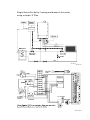
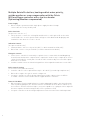
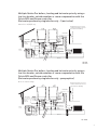
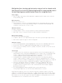
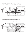
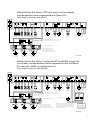
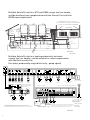
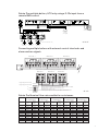
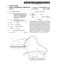
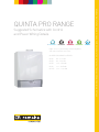
Suggested Schematics with Control and Power Wiring Details SUPER CONDENSING HIGH EFFICIENCY FULLY MODULATING 107% NCV ≥ 82/71°C 108.9% NCV ∆T 50/30°C BOILER CONTROL PREMIX BURNER CLEAN COMBUSTION ULTRA LOW NOx BREEAM EXCELLENT RECYCLABLE MATERIALS High efficiency wall hung condensing boiler with ultra low NOx emissions PANTONE 287 EC PANTONE 2985 EC PANTONE Process Black EC PANTONE 200 EC QUINTA PRO RANGE OUTPUTS PANTONE 287 EC QP30: 8.0 - 31.4 kW QP45: 8.0 - 43.0 kW QP65: 12.0 - 65.0 kW QP90: 14.1 - 89.5 kW QP115: 16.6 - 114.0 kW PANTONE 2985 EC PANTONE Process Cyan EC PANTONE 376 EC PANTONE Process Cyan EC REMEHA QUINTA PRO RANGE - SUGGESTED SCHEMATICS WITH CONTROL AND POWER WIRING DETAILS QUINTA PRO RANGE Schematics with Control Page Control Options for the Quinta Pro Series of Boilers p3 External controls by others Simple Quinta Pro boiler domestic installation - Typical ‘S’ plan, heating and hot water p4-5 Single Quinta Pro boiler, heating only p6-7 Single Quinta Pro boiler, heating only with low loss header p8-9 Single Quinta Pro boiler, heating and priority hot water using a low loss header and pump or valve kit p10-13 Remeha supplied controls Single Quinta Pro boiler, heating only using the iSense controller (room/weather compensation) p14-16 Single Quinta Pro boiler, heating and Priority DHW using the iSense controller (room or outside compensation) p17-19 Multiple Quinta Pro boilers HTG only using a low loss header with the Celcia MC4 and iSense (room or outside compensation) p20-21 Multiple Quinta Pro boilers HTG and Priority DHW using a low loss header with the Celcia MC4 and iSense (room or outside compensation) p22-24 Multiple boilers, heating and hot water using a low loss header with the iSense Pro controller (optimising/weather compensated control for dual heating zone and hot water from all or single boilers) p25-30 Connecting multiple boilers with external control interlocks and alarm and run signals p31 Quinta Pro nominal flow rates and boiler resistances p31 Note: We supply the Grundfoss 25/80 (Part No. S101621) as standard for the full Quinta Pro range. This will alter due to changes in EU regulations. The Quinta Pro 30 will operate on speed 1, the 45 and 65 will operate on speed 2, and the 90 and 115 will operate on speed 3. They are intended to act as a shunt pump. In the layouts illustrated, they are designed to operate on a 20ºC Delta TΔ. If using a pump without a low loss header, please take into account both the boiler and system resistance and also when being used in conjunction with a calorifier and low loss header. Contact our sales or technical departments for further assistance. The hydraulic and control layouts illustrated in this brochure are for guidance only and must be used in conjunction with the Quinta Pro and iSense Pro installation and service manuals. They do not constitute a full system design. Remeha Commercial accept no liability for any loss or damage rising from any errors or omissions that may be inadvertently contained in this booklet. When connecting a control cable to the OT terminals on the main control PCB, disconnect and remove the factory fitted lead connected to the IF- 01 PCB. Some earths and neutrals are omitted for clarity. All systems, mechanical and electrical, must be installed to the current regulations by a suitably qualified engineer. 2 Control Options for the Quinta Pro 30 / 45 / 65 / 90 and 115 series The Remeha range of Quinta Pro boilers are supplied as standard with an “Open Therm” control interface which enables direct weather compensation using Remeha single and multi boiler controls. The customer can choose to use external control options supplied by others without affecting boiler performance. Supplied by others On/off control: • Boiler requires a permanent 230v supply and is enabled using a volt free switch/relay. The boiler will modulate its output to maintain the flow temperature setpoint, normally 80ºC, but can be adjusted on the boiler between 20ºC and 90ºC 0-10 volt control: •Boiler requires a permanent 230v supply and is enabled and modulated using a 0-10 volt signal from a Building Management System or quality panel mounted optimiser/ compensator. The control can be flow temperature or percentage output based •Temperature based example: if 56ºC flow is required from the boiler, the control will need to supply 5.6v. The output will be modulated to maintain a flow temperature of 56ºC •Percentage based example: if the control logic requires that a boiler should be running at 33%, the control will need to supply 3.3v to the boiler. The boiler will run at 33% output with a variable flow temperature •Applications - domestic/commercial and industrial installations, with a variety of heat emitters, DHW via calorifiers or plate heat exchangers, and installations where a variety of different temperature zones are required at the same time Supplied by Remeha Commercial as optional extras iSense Controller - Single/multi boiler weather compensating controller • A simple to operate room/boiler mounted thermostat/timer which can be used with a combination of outside/room and flow temperature sensors to vary the boiler output (flow temp) to suit weather conditions. The iSense can be installed in a reference room and can also be mounted in a boiler when used in weather compensated mode. It has a 7 day timer with multiple on/off and night setback periods, holiday function, frost protection and manual override Celcia MC4 • Multiple boiler weather compensating controller with step control (up to 4 boilers) to be used in conjunction with the iSense controller • The iSense can be mounted in a reference room, in the plant room or on the boiler • The MC4 is mounted adjacent to the boiler group iSense Pro - Multiple boiler weather compensating controller with sequence control (up to 8 boilers) • Optimiser compensator which can provide 2 timed heating zones and uses a combination of outside, flow and room temperature to vary the boiler output (flow temp) to suit weather conditions. Can also provide time control to DHW circuit. The iSense Pro controller is mounted in a wall box when used with the Quinta Pro and is complete with timer, night setback, frost protection and pump cycling protection. The iSense Pro controller will sequence and rotate the lead boiler on multiple installations. This controller also has the ability to accept remote extension timers, supplied as an optional extra, which will allow the heating system to run on daytime compensation outside the normal timed settings without need for access or interference to the boiler or controller. Ideal for school lettings/night classes etc. Note: We do not advise using a combination of external and built-in controls as in most cases there can be no interface between them; it is likely they will ‘conflict’ with each other and neither will work properly. The exception to this is when using the iSense Pro kit KT1154 in conjunction with a Remote BMS controller (see page 31). 3 Simple Quinta Pro boiler domestic installation Typical ‘S’ plan, heating and hot water (Time and temperature control by others) Power Supply • Boiler requires a permanent 230v single phase supply fused at 6.3 amps connected to the factory fitted fly lead Boiler Control Settings (see 5.7.2 in technical documentation) • Set boiler code P1 to the required flow temp i.e. 80 = 80ºC (system design requirements) • Boiler will recognise the control being used • Use the zone valve end switches to provide the volt free switch pair on OT on the main control PCB to enable the boiler • Boiler output will vary between 18% part load set point and 100% full load set point to achieve the boiler flow set point (code P1) System Components (not supplied) • Simple two channel time clock providing 230v switched supplies to control heating and domestic hot water • System pump • Cylinder thermostat • Room thermostat • HTG and DHW zone valves c/w a single end switch (closes on valve fully open) • Wiring centre Note: 1. Maintain polarity on all connections 2. Some Neutral and Earth connections have been omitted for clarity 3. The schematic is for guidance only and does not constitute a design 4. Heating and hot water can be operated independently or simultaneously with this layout provided the control selected will allow it 4 Quinta Pro single boiler heating and dome stic hot water, usinga simple ‘S’ Pla n Quinta single boiler heating andand dome stic hot wa ter, usinga Single Pro Quinta Pro boiler, heating domestic hot water, simple Pla n ‘S’ Plan using a‘S’simple QP 001S QP 001S QP 001S O O Shunt Shunt QP 001SA QP 001SA QP 001SA 5 Single Quinta Pro boiler, heating only (Time and temperature control by others) Power Supply • Boiler requires a permanent 230v single phase supply fused at 6.3 amps connected to the factory fitted fly lead Boiler Interlocks (for pressure switches etc.) • Safety Interlock - remove the existing link and fit volt free switch pair to BL on the main control PCB. If the circuit is open the boiler will go to a shut down mode displaying code 9 and will restart when the circuit is closed Indication Controls (to report actual function) • Common Alarm - volt free relay on SCU-X01 (see boiler manual for full details) • Boiler Run - volt free relay on SCU-X01 (see boiler manual for full details) Boiler Control Settings (see 5.7.2 in technical documentation) • Connect the external controls (volt free) to the OT terminals on the main control PCB (on/off). Boiler will modulate to the set point set in P1 or the 0 -10v terminals on the IF-01. Control option based on temperature or output can be adjusted on the jumper on the IF-01. (See installation manual for full details) • Boiler will recognise the type of control being used • Set boiler code P1 to the required flow temp i.e. 80 = 80ºC (system design requirements) •Pump: connect the heating pump to terminals shown on the PCB SCU - S02 max 400Va (1.5 amp). Alternatively, pump can be connected to the fly lead supplied with the boiler to plug X81; this a max duty of 200w (0.8 amp) 6 Quinta Pro single boiler heating only Single Pro Quinta Proboiler boiler,heating heatingonly only Quinta single QP 002 QP 002 QP 002 QP 002A QP 002A 002A QP 7 Single Quinta Pro boiler, heating only with low loss header (Time and temperature control by others) Power Supply • Boiler requires a permanent 230v single phase supply fused at 6.3 amps connected to the factory fitted fly lead Boiler Interlocks (for pressure switches etc.) • Safety Interlock - remove the existing link and fit volt free switch pair to BL on the main control PCB. If the circuit is open the boiler will go to a shut down mode displaying code 9 and will restart when the circuit is closed Indication Controls (to report actual function) • Common Alarm - volt free relay on SCU-X01 (see boiler manual for full details) • Boiler Run - volt free relay on SCU-X01 (see boiler manual for full details) Boiler Control Settings (see 5.7.2 in technical documentation) • Boiler will recognise the type of control being used • Set boiler code P1 to the required flow temp i.e. 80 = 80ºC (system design requirements) • Connect the external controls (volt free) to the OT terminals on the main control PCB (on/off). Boiler will modulate to the set point set in P1 or the 0 -10v terminals on the IF- 01. Control option based on temperature or output can be adjusted on the jumper on the IF- 01. (See installation manual for full details) • Pumps: connect pump PM1 to the heating pump terminals shown on the PCB SCU - S02 max 400Va (1.5 amp). Connect the shunt pump SH1 to the pump fly lead supplied with the boiler to plug X81 8 Quinta Pro single boiler heating only with loss heading Single Quinta Pro boiler, heating only with low loss header Quinta Pro single boiler heating only with loss heading QP 003 QP 003 QP 003 QP 003A QP 003A QP 003A 9 Single Quinta Pro boiler, heating with priority hot water using a low loss header and pump or valve kit (Time and temperature control by others) Power Supply • Boiler requires a permanent 230v single phase supply fused at 6.3 amps connected to the factory fitted fly lead Boiler Interlocks (for pressure switches etc.) • Safety Interlock - remove the existing link and fit volt free switch pair to BL on the main control PCB. If the circuit is open the boiler will go to a shut down mode displaying code 9 and will restart when the circuit is closed Indication Controls (to report actual function) • Common Alarm - volt free relay on SCU-X01 (see boiler manual for full details) • Boiler Run - volt free relay on SCU-X01 (see boiler manual for full details) Boiler Control Settings (see 5.7.2 in technical documentation) • Boiler will recognise the type of control being used • Set boiler code P1 to the required flow temp i.e. 80 = 80ºC (system design requirements) • Connect the external controls (volt free) to the OT terminals on the main control PCB (on/off). Boiler will modulate to the set point set in P1 •Pumps: connect pump PM1 to the heating pump terminals shown on the PCB SCU - S02 max 400Va (1.5 amp). Connect the shunt pump SH1 to the fly lead supplied with the boiler to plug X81 max 200w (0.8 amp). On pump installations, connect the shunt pump to the terminals shown; a contactor or relay will be required if loading exceeds 1.5 amps • 3-way valve: on the 3-way valve option, connect the valve to the terminals shown on the PCB SCU – S02 Important: When using the Remeha supplied low loss header and pump kit and the DHW diverting valve or primary pump kit, the calorifier must be sited within 3M of the boiler. In both cases, the DHW cylinder must be a high recovery unit capable of accepting the full or adjusted DHW output of the boiler being used (reference parameter P18). 10 Single Quinta Pro boiler, Quinta Pro boiler heating with priority hot water using low Quinta Pro single single boilerheating heatingwith withpriority priorityhot hotwater waterusing usingaa alow low loss header. 3-way valve DHW priority Quinta Pro 30/45/65 only loss header. Three way valve DHW priority Quinta Pro 30/45/65 loss header. Three way valve DHW priority Quinta Pro 30/45/65 only only QP 004 QP QP 004 004 Single Quintasingle Pro boiler, heating with priority hot water using aa Quinta Quinta Pro Pro single boiler boiler heating heating with with priority priority hot hot water water using using a low loss header pump option. DHW priority can be used on all low loss header pump option DHW priority can be used low loss header pump option DHW priority can be used on on all all Quinta Pro range Quinta Pro range Quinta Pro range QP 004A QP QP 004A 004A 11 Single Quinta Pro boiler, heating with priority hot water using a low loss header (3-way valve option) Note: Control PCB s are shown diagrammatically Earths are omitted for clarity Cylinder Thermostat Note: Control PCB s are shown diagrammatically Earths are omitted for clarity 230v fused supply for 2 port valve 2(connected Port to spring boiler supply) return valve Safety Limiter 3 way valve 2 C 1 Thermostat 3 way valve Cylinder Boiler Thermostat Tdhw 230v fused Wiring detail of controls when using a for Remeha Commercial Calorifier,supply a volt free HWS time control and a 2 Port 2 spring portreturn valve valve. If using a different type of calorifier, please (connected to follow manufacturer’s instructions regarding boiler supply) control and wiring details Wiring detail of controls when using a Remeha Commercial Calorifier, a volt free HWS time control and a 2 Port spring return valve. If using a different type of calorifier, please follow manufacturer’s instructions regarding control and wiring details 2 C 1 Safety Limiter HWS time control 230v Fused Supply (connected to boiler supply) 2 Live Neutral Boiler Signal out (volt free) Boiler Tdhw HWS time control C 1 2 C 1 Orange Grey Blue Brown Factory fitted supply lead to be connected to a 230v fused spur for boiler permanent supply Time/temp control HTG (volt free) Time control DHW (volt free) Thermostat 2 Port spring return valve 2 Port Spring Return Motorised Valve 230v Fused Boiler Signal in (volt free) Supply (connected to boiler supply) Live Neutral Boiler Signal out (volt free) Orange Grey Blue Brown Factory fitted supply lead to be connected to a 230v fused spur for boiler permanent supply Time/temp control HTG (volt free) Time control DHW (volt free) 2 Port Spring Return Motorised Valve Boiler Signal in (volt free) QP 004B Single Quinta Pro boiler, heating with priority hot water using a low loss header (Pump option) Note: Control PCBs are shown diagrammatically Earths are omitted for clarity 2 Port spring return valve Cylinder Thermostat Pump PM1 Shunt pump SH1 Thermostat Safety Limiter Note: Control PCBs are shown diagrammatically Earths are omitted for clarity Contactor or relay required if both pumps 230v fused supply for 22 Port port valve spring (connected toCylinder return boiler supply)Thermostat valve 230v fused supply for 2 port valve (connected to boiler supply) Wiring detail of controls when using aPM1 Remeha and SH1 loading exceeds 1.5 amps Commercial Calorifier with a 2 Port spring return 2 C 1 2 C 1 valve. If using a different type of calorifier, please follow manufacturer’s instructions Pump Pump Shunt pumpregarding Thermostat Safety Limiter control and wiring details PM1 PM2 SH1 230v Fused HWS time Supply Boiler Wiring detail of controls when using a Remeha control (connected to Tdhw Commercial Calorifier with a 2boiler Port spring supply)return 2 valve. If using a different type of calorifier, pleaseLive follow manufacturer’s instructions regarding Neutral control and wiring detailsBoiler Signal out (volt free) Boiler Tdhw 12 Pump PM2 HWS time control 230v Fused Boiler Signal in (volt free) Supply (connected to boiler supply) Live Neutral Boiler Signal out (volt free) Boiler Signal in (volt free) C 1 2 C Orange Grey Blue Brown Factory fitted supply lead to be connected to a 230v fused spur for boiler permanent supply Time/temp control HTG (volt free) Time control DHW (volt free) Contactor or relay required if both pumps PM1 and SH1 loading exceeds 1.5 amps 1 2 Port Spring Return Motorised Valve Orange Grey Blue Brown Factory fitted supply lead to be connected to a 230v fused spur for boiler permanent supply Time/temp control HTG (volt free) Time control DHW (volt free) 2 Port Spring Return Motorised Valve QP 004C QP 004C Wiring detail of controls when using a Remeha Commercial Calorifier. If using a different type of calorifier, please follow manufacturer’s instructions regarding control and wiring details. QP004D QP 004D QP004D Wiring detail of controls when using a Remeha Commercial Calorifier with a 2 Port spring return valve and an iSense or Open Therm controller. If using a different type of calorifier, please follow manufacturer’s instructions regarding control and wiring details. Set Boiler parameter P37 to 0. 2 Note: Calorifier Thermostat temperature should be set 5oC higher than the iSense control hot water setting. Boiler C 2 1 C 2 1 C 2 1 C 1 230v Fused Supply Boiler R L 230v Fused Supply RL Live Neutral Boiler Signal out (volt free) Live Neutral Boiler Signal out (volt free) Boiler Signal in (volt free) Boiler Signal in (volt free) QP004E QP004E QP 004E 13 Single Quinta Pro boiler, heating only using the iSense controller (room or weather or room/weather compensated) Power Supply • Boiler requires a permanent 230v single phase supply fused at 6.3 amps connected to the factory fitted fly lead Boiler Interlocks (for pressure switches etc.) • Safety Interlock - remove the existing link and fit volt free switch pair to BL on the main control PCB. If the circuit is open the boiler will go to a shut down mode displaying code 9 and will restart when the circuit is closed Indication Controls (to report actual function) • Common Alarm - volt free relay on SCU-X01 (see boiler manual for full details) • Boiler Run - volt free relay on SCU-X01 (see boiler manual for full details) Boiler Control Settings (see 5.7.2 in technical documentation) • Set boiler code P1 to the required flow temp i.e. 80 = 80ºC (system design requirements) • Boiler will recognise the type of control setting used Fitting the Control • For room compensation, fit the control in a normally occupied reference room within the building being heated • For room/weather compensation, an outside sensor can be fitted. If requiring weather compensation only, the iSense can be fitted into the boiler control panel. In this case an outside sensor must be fitted and connected to ‘Tout’ in the boiler on the main control PCB • Connect the 2 wire control to the OT terminals on the main PCB. Please refer to the instructions supplied with the iSense controller package • Set up the controller to suit the design requirements and occupancy times for HTG in accordance with the instruction documents supplied with the controller Note: The iSense controller can provide both room or weather compensation or room and weather compensation. Room compensation = iSense fitted in a reference room, no outside sensor Weather compensation = iSense fitted in a boiler or plant room, outside sensor required Room/weather compensation = iSense fitted in a reference room, outside sensor required 14 Quinta Pro single boiler heating only room compensation using the Single Pro boiler, heating only only,room roomcompensation compensationusing usingthe the QuintaQuinta Pro single boiler heating iSense controller iSense iSensecontroller controller 1.6M 1.6M Suggested height in room Suggested height in room Normal position for the iSense controller Normal position for the iSense controller mounted in reference room within the building mounted in reference room within the building (room compensation) (room compensation) 100m Max 100m Max 230v Supply 230v Supply Pump PM1 Pump PM1 Condensate Condensate Gas Gas Flow Flow Return Return QP 005 QP005 005 QP Single Quinta Pro boiler, heating only, weather compensation using Quinta Pro single boiler heating only weather compensation using the iSense controller Quinta Procontroller single boiler heating only weather compensation using the iSense the iSense controller Normal position for the iSense controller mounted reference room within the building Normal in position for the iSense controller 100m Max 100m Max 100m Max 100m Max Outside sensor onOutside North sensor facing wall on North facing wall 230v Supply 230v Supply Pump PM1 1.6M 1.6M Suggested height in room Suggested height in room mounted in reference room within the building iSense can be fitted in the boiler if used for weather compensation only iSense can be fitted in the boiler if used for weather compensation only Pump PM1 Condensate Condensate Gas Flow Gas Flow Return Return QP QP 005A 005A QP 005A 15 Single Quinta Pro boiler heating only using the iSense controller Single Single Quinta Quinta Pro Pro boiler boiler,heating heatingonly onlyusing usingthe theiSense iSensecontroller controller Note: Control PCBs are shown diagrammatically Earths are omitted for clarity OT Factory fitted supply lead to be connected to a 230v fused spur for boiler permanent supply iSense controller Factory fitted supply lead to be connected to a 230v fused spur for boiler permanent supply iSense controller Note: Control PCBs are shown diagrammatically Earths are omitted for clarity Pump PM1 OT QP 005B Pump PM1 QP 005B QP 005B Single Quinta Pro boiler heating only using the iSense controller Single Quinta Pro heating only using the iSense controller (room/weather or boiler, weather compensation) (room/weather or weather compensation) Single Quinta Pro boiler heating only using the iSense controller (room/weather or weather compensation) Note: Control PCBs are shown diagrammatically Earths are omitted for clarity OT Factory fitted supply lead to be connected to a 230v fused spur for boiler permanent supply iSense controller Factory fitted supply lead to be connected to a 230v fused spur for boiler permanent supply iSense controller Outside Sensor Note: Control PCBs are shown diagrammatically Earths are omitted for clarity OT Pump PM1 Outside Sensor Pump PM1 QP 005C QP 005C 16 Single Quinta Pro boiler, heating with hot water priority, heating room or weather compensated with the iSense controller (Optimising/Weather compensated heating with timed hot water) Power Supply • Boiler requires a permanent 230v single phase supply fused at 6.3 amps connected to the factory fitted fly lead Boiler Interlocks (for pressure switches etc.) • Safety Interlock - remove the existing link and fit volt free switch pair to BL on the main control PCB. If the circuit is open the boiler will go to a shut down mode displaying code 9 and will restart when the circuit is closed Indication Controls (to report actual function) • Common Alarm - volt free relay on SCU-X01 (see boiler manual for full details) • Boiler Run - volt free relay on SCU-X01 (see boiler manual for full details) Boiler Control Settings (see 5.7.2 in technical documentation) • Set boiler code P1 to the required flow temp i.e. 80 = 80ºC (system design requirements) • Boiler will recognise the type of control setting used • Fit the control in a normally occupied reference room within the building being heated. Refer to the instructions supplied with the control package • Set up the controller to suit the design requirements and occupancy times for heating and hot water in accordance with the instruction documents supplied with the controller • Install the outside sensor on a North facing wall in a sheltered position and connect to terminals ‘Tout’ on the main PCB of the boiler DHW Control Diverting valve option: Connect valve to the terminals shown, connect shunt pump PM1 to the terminals shown. Connect valve ports AB, A and B as shown (AB = boiler, A = hot water, B = heating) Primary Pump option: Connect pump PM1 to the terminals shown Connect shunt pump to the terminals shown Note: This option will only operate with a calorifier sensor. This is to allow the iSense to control the hot water times. 17 Quinta Quinta Pro single Single Pro boiler boiler,heating heatingand andhot hotwater waterpriority. priority.Heating Heatingroom or outside weather compensated with the iSense controller. room or outside weather compensated with the iSense controller. Three way valve hot water priority Quinta Pro 30/45/65 only 3-way valve hot water priority Quinta Pro 30/45/65 only 100m Max Max 100m 230v 230v Supply Supply 100m Max Max 100m 1.6M 1.6M Suggested Suggestedheight heightin inroom room Normal position position for for the the iSense iSense controller controller Normal mounted in in reference reference room room within within the the building building mounted (room compensation) compensation) (room Pump PM1 PM1 Pump DHW Sensor Sensor DHW Condensate Condensate Gas Gas Flow Flow AB AB A B A B DHW Diverting valve valve DHW Diverting Port spring spring return return valve valve 22 Port Bypass valve valve Bypass Return Return QP 006 006 QP QP 006 Quinta Quinta Pro single Single Pro boiler boiler,heating heatingand andhot hotwater waterpriority. priority.Heating Heatingroom or outside weather compensation with the iSense controller. room or outside weather compensation with the iSense controller. Pump option hot water priority can be used on all Quinta Pro range Pump option hot water priority can be used on all Quinta Pro range 100m Max Max 100m 230v 230v Supply Supply 100m Max Max 100m Outside sensor sensor on on Outside North facing facing wall wall North DHW Sensor Sensor DHW Pump PM1 PM1 Pump 1.6M 1.6M Suggested Suggestedheight heightin inroom room Normal position position for for the the iSense iSense controller controller Normal mounted in in reference reference room room within within the the building building mounted (room compensation) compensation) (room iSense can can be be fitted fitted into into boiler boiler iSense control panel panel for for outside outside control weather compensation compensation only only weather Pump PM2 PM2 Pump Condensate Condensate Gas Gas Flow Flow Port spring spring 22 Port return valve valve return Bypass valve valve Bypass Return Return QP QP 006A 006A 18 Single Quinta Pro boiler, heating and priority hot water using the iSense controller (3 Port valve option) OT Factory fitted supply lead to be connected to a 230v fused spur for boiler permanent supply Outside Sensor iSense controller 3 way valve Calorifier Sensor Note: Control PCBs are shown diagrammatically Earths are omitted for clarity Pump PM1 Boiler parameter P37 must be set to 0 2 Port spring return valve See drawing QP004E 230v fused supply for 2 port valve QP 006B Single Quinta Pro boiler, heating and priority hot water using the iSense controller (Pump option) Note: Control PCBs are shown diagrammatically Earths are omitted for clarity OT Factory fitted supply lead to be connected to a 230v fused spur for boiler permanent supply See drawing QP004E Outside Sensor iSense controller Pump PM1 Pump PM2 Calorifier Sensor 2 Port spring return valve Boiler parameter P37 must be set to 0 230v 3amp fuses supply for 2 port valve QP 006C 19 Multiple Quinta Pro boilers, heating only, outside weather or room compensation with the Celcia MC4 and iSense controller with a low loss header (Optimising/weather compensated) Power Supply • Boilers require a permanent 230v single phase supply fused at 6.3 amps connected to the factory fitted fly lead Boiler Interlocks (for pressure switches etc.) • Safety Interlock - remove the existing link and fit volt free switch pair to BL on the main control PCB. If the circuit is open the boiler will go to a shut down mode displaying code 9 and will restart when the circuit is closed Indication Controls (to report actual function) • Common Alarm - volt free relay on SCU-X01 (see boiler manual for full details) • Boiler Run - volt free relay on SCU-X01 (see boiler manual for full details) Fitting the Controls • Fit the iSense controller in a normally occupied reference room within the building being heated if room and weather compensation is required. If weather only is required, the iSense can be fitted in a boiler control panel. Install the MC4 controller adjacent to the boiler plant and connect as shown • Install the outside sensor on a North facing wall, and connect to the MC4 (for weather compensation only) Boiler Control Settings (see 5.7.2 in technical documentation) • Set boiler code P1 to the required flow temp i.e. 80 = 80ºC (system design requirements) • Boiler will recognise the type of control setting used • Set up the controller to suit the design requirements and occupancy times for HTG in accordance with the instruction documents supplied with the controller Note: Installation can be designed without the use of a low loss header. Omit the header and shunt pumps. A heating pump must be capable of overcoming the combined resistance of the boiler, system and pipe work. A reverse return with a common loop and single primary pump would be suitable. 20 Multiple Quinta Pro boilers, HTG only using a low loss header, outside weather/room compensation with the Celcia MC4 and iSense controller 1.6M 1.6M Suggested height room Suggested height in in room Normal position for the iSense Normal position forin the iSense controller mounted reference controller mounted in reference room within the building room within the building 100m Max 100m Max Celcia MC4 Celcia MC4 100m Max 100m Max 230v Supply 230v Supply 230v Supply 230v Supply Shunt Pump Shunt Pump Shunt Pump Shunt Pump Condensate Condensate Gas Gas Flow Flow TwTowo to tfo fo ourur b boiloile ers rs Outside sensor Outside on Northsensor on North facing wall facing wall iSense can be mounted iSense mounted in boilercan for be weather in boiler for weather compensation only compensation only Pump PM1 Pump PM1 Htg Flow sensor Htg Flow sensor Return Return QP 007 Multiple Quinta Pro boilers, heating only using a low loss header, outside weather or room compensation with the Celcia MC4 and iSense controller iSense mounted in reference room (or boilermounted for weather compensation iSense in reference room only) (or boiler for weather compensation only) OT - Bus DIGI OT - Bus Note: Control PCBs are shown diagrammatically Note: Control PCBsfor are shown diagrammatically Earths are omitted clarity Earths are omitted for clarity Boiler No. 1 Boiler No. 1 Factory fitted supply lead to be connected Factory fitted supply to lead a 230v fused spur for to be connected boiler permanent supply to a 230v fused spur for boiler permanent supply Shunt pump Shunt pump Shunt pump Shunt pump Shunt pump Shunt pump OT X81 Boiler No. 4 Boiler No. 4 Shunt pump Shunt pump OT OT X81 Outside sensor on North facing wall Outside sensor on North facing wall 100max 100max DIGI OT OT X81 X81 Boiler No. 3 Boiler No. 3 OT X81 X81 System Pump PM1 (MaxPump 1amp)PM1 System (Max 1amp) Switch spur 230v Rated atspur 3amps Switch 230v Rated at 3amps MC4 L N E E L N E E 17 18 19 17 18 19 1 2 3 4 5 6 7 8 9 10 11 12 13 14 1 2 3 4 5 6 7 8 9 10 11 12 13 14 Boiler No. 2 Boiler No. 2 Flow Sensor Mount on flow pipework to Flow Sensor register a common flow to Mount on flow pipework temperature register a common flow temperature QP 007A QP 007A QP 007A 21 Multiple Quinta Pro boilers, heating and hot water priority, outside weather or room compensation with the Celcia MC4 and iSense controller with a low loss header (Optimising/Weather compensated) Power Supply • Boilers require a permanent 230v single phase supply fused at 6.3 amps connected to the factory fitted fly lead Boiler Interlocks (for pressure switches etc.) • Safety Interlock - remove the existing link and fit volt free switch pair to BL on the main control PCB. If the circuit is open the boiler will go to a shut down mode displaying code 9 and will restart when the circuit is closed Indication Controls (to report actual function) • Common Alarm - volt free relay on SCU-X01 (see boiler manual for full details) • Boiler Run - volt free relay on SCU-X01 (see boiler manual for full details) Fitting the Controls • Fit the iSense controller in a normally occupied reference room within the building being heated if room and weather compensation is required. If weather only is required, the iSense can be fitted in a boiler control panel. Install the MC4 controller adjacent to the boiler plant and connect as shown. • Install the outside sensor on a North facing wall in a sheltered position and connect to the MC4 Boiler Control Settings (see 5.7.2 in technical documentation) • Set boiler code P1 to the required flow temp i.e. 80 = 80ºC (system design requirements) • Boiler will recognise the type of control setting used • Set up the controller to suit the design requirements and occupancy times for HTG in accordance with the instruction documents supplied with the controller Domestic Hot Water • When using the Remeha supplied low loss header and pump kit and the hot water diverting valve or primary pump kit, the calorifier must be sited within 3m of the boiler. In both cases, the hot water calorifier must be a high recovery unit capable of accepting the full or adjusted hot water output of the boiler being used (reference parameter P18) •Set up the controller to suit the design requirements for the hot water times and temperature 22 Multiple Proboiler boilers, heating water priority Quinta ProQuinta multiple heating andand hot hot wa ter priority usingusing alow a low header loss header, outside weather room compensation loss outside, weather orroomor compensation with thewith Ce lciathe Celcia MC4 andcontroller iSense controller MC4 and iSense . (Hot water produce by single boiler 3 port valve) (Hot water produce by single boiler onlyonly - 3 -port valve) Quinta Pro 30/45/65 only 100m Max Celcia Celcia MC4 MC4 100m Max Outside sensor sensor Outside on North North on facing wall wall facing 230v 230v Supply Supply 230v 230v Supply Supply Shunt Pump Pump Shunt Shunt Pump Pump Shunt Condensate DHW DHW Sensor Sensor fou r bo ilers AB AB AA B B Calorifier Calorifier Port spring spring return return valve valve 22 Port Two to Bypass Bypass valve valve 1.6M Suggested height in room Normal position for the iSense controller mounted in reference room within the building Pump PM1 PM1 Pump Gas Flow Htg Flow Flow sensor sensor Htg Return QP QP 008 008 Multiple Proboiler boilers, heating water priority Quinta ProQuinta multiple heating andand hot hot wa ter priority usingusing alow a low header loss header, outside weather room compensation loss outside, weather orroomor compensation with thewith Ce lciathe Celcia MC4 andcontroller iSense controller MC4 and iSense . waterproduce producebybysing single boiler - pump option) (Hot water le boiler onlyonly - pump option ) All of the Quinta range 100m Max Celcia Celcia MC4 MC4 100m Max Outside sensor sensor Outside on North North on facing wall facing wall 230v 230v Supply Supply 230v 230v Supply Supply Shunt Pump Pump Shunt Shunt Pump Pump Shunt 1.6M Suggested height in room Normal position for the iSense controller mounted in reference room within the building DHW Pump Pump DHW Condensate Calorifier Calorifier Port spring spring 22 Port return valve valve return Two to Bypass Bypass valve valve fou r bo iler s DHW DHW Sensor Sensor Pump PM1 PM1 Pump Gas Flow Htg Flow Flow sensor sensor Htg Return QP 008A QP 008A 23 Quinta Pro multiple boilers heating and priority hot water using a Quinta Pro multipleboilers, boilers heating and andpriority priorityhot hotwater water usingaa Multiple low loss, Quinta outsidePro weather orheating room compensation with the using Celcia low loss loss,header, outsideoutside weather or room compensation with the Celcia low weather or room compensation with the MC4 and iSense controller. MC4 and iSense controller. Celcia MC4produced and iSense (Hot water bycontroller single boiler only - 3 Port valve) (Hot water produced bysingle singleboiler boileronly only--33Port Portvalve) valve) (Hot water produced by iSense mounted in reference room (or boiler control panel) iSense mounted in reference room (or boiler control panel) OT - Bus DIGI OT - Bus 100m max Note: Control PCBs are shown diagrammatically Earths are omitted for clarity Note: Control PCBs are shown diagrammatically Earths are omitted for clarity 2 Port spring return valve Factory fitted 2 Port spring supply lead to Shunt pump Calorifier return valve Factory fitted Thermostat be connected supply lead to Shunt pump Calorifier See drawing QP004E to a 230v fused Thermostat be connected 230v fused supply spur for boiler See drawing QP004E to a 230v fused for 2 port valve permanent supply 230v fused supply spur for boiler for 2 port valve permanent supply Shunt pump Shunt pump Shunt pump Boiler Shunt pump Shunt pump Shunt pump Parameter P37 System Pump PM1 Switch spur 230v Boiler Rated at 3amps (Max 1amp) must be set to 0 On/off On/off On/off Parameter P37 System Pump PM1 Switch spur 230v Rated at 3amps (Max 1amp) must be set to 0 On/off On/off On/off OT OT OT OT X81 OT X81 X81 MC4 MC4 L N E E X81 Boiler No. 3 Boiler No. 4 OT X81 X81 Boiler No. 4 Outside sensor on North facing wall Outside sensor on North facing wall 100m max DIGI 17 18 19 L N E E 1 2 3 4 5 6 7 8 9 10 11 12 13 14 17 18 19 1 2 3 4 5 6 7 8 9 10 11 12 13 14 Boiler No. 2 Boiler No. 3 Boiler No. 2 Flow Sensor Mount on flow pipework to Flow Sensor register a common flow Mount on flow pipework to temperature register a common flow temperature QP 008B 008B QPQP 008B Quinta Pro multiple boilers heating using aa Multiple Quinta Pro boilers, heating and and priority hot water using Quinta Pro multiple boilers heating and priority hot water using a low outside outside weatherweather or roomorcompensation with thewith Celcia low loss, loss header, room compensation the low loss, outside weather or room compensation with the Celcia MC4 and iSense controller. Celcia MC4 and iSense controller MC4 and iSense controller. (Hot water produced by single boiler only (Hot only -- pump pump option) option) (Hot water produced by single boiler only - pump option) iSense mounted in reference room (or boiler control panel) iSense mounted in reference room (or boiler control panel) OT - Bus DIGI OT - Bus 2 Port spring Shunt pump X81 X81 Boiler No. 4 Boiler No. 4 OT Shunt pump On/off On/off OT must be set to 0 100m max Note: Control PCBs are shown diagrammatically Earths are omitted for clarity Note: Control PCBs are shown diagrammatically Earths are omitted for clarity Shunt DHW return valve Factory fitted pump pump 2 Port spring supply lead to Calorifier Shunt DHW return valve Factory fitted pump Thermostat pump be connected supply lead to Calorifier See drawing QP004E to a 230v fused Thermostat be connected 230v fused supply spur for boiler See drawing QP004E to a 230v fused for 2 port valve permanent supply 230v fused supply spur for boiler for 2 port valve permanent supply Shunt pump Shunt pump Shunt pump Shunt pump Boiler Parameter P37 Boiler On/off must be set to 0 Parameter P37 Outside sensor on North facing wall Outside sensor on North facing wall 100m max DIGI On/off On/off OT X81 X81 Boiler No. 3 Boiler No. 3 OT On/off OT X81 X81 OT System Pump PM1 Switch spur 230v Rated at 3amps (Max 1amp) System Pump PM1 Switch spur 230v Rated at 3amps (Max 1amp) MC4 MC4 L N E E L N E E 17 18 19 17 18 19 1 2 3 4 5 6 7 8 9 10 11 12 13 14 1 2 3 4 5 6 7 8 9 10 11 12 13 14 Boiler No. 2 Boiler No. 2 Flow Sensor Mount on flow pipework to Flow Sensor register a common flow Mount on flow pipework to temperature register a common flow temperature QP QP008C 008C QP 008C 24 iSense Pro Multiple Boiler Controller The iSense Pro kits listed below show the basic kits for two boilers. Any additional boilers (up to 8 boilers) will require an extra Open Therm (OT) interface (AD287) and a Bus Cable (1 x AD124 -1.5m). Systems with two circuits will require two extra flow sensors (AD199). All installations and fitting instructions are supplied with the iSense Pro kits or available via our website www.remeha.co.uk Basic Two Boiler Kit: Quinta Pro Option AD244 Kit No. KT1089 1 x AD283: iSense Pro complete with wall box Part No. 100018256 1 x AD244: Room Sensor Basic (no control) Part No. 100012044 1 x AD287: Open Therm Interface (not required in first boiler) Part No. 100018921 1 x AD134: Bus Cable 12m (iSense controller to second boiler) Part No. 88017851 1 x AD199: Flow Sensor Part No. 88017017 1 x AF60: Outside Sensor Part No. 95362450 1 x KVT60: DHW Sensor Part No. 95362448 Basic Two Boiler Kit: Quinta Pro Option AD278 Kit No. KT1090 1 x AD283: iSense Pro complete with wall box Part No. 100018256 1 x AD278: Room Sensor Control (temperature control) Part No. 100017732 1 x AD287: Open Therm Interface (not required in first boiler) Part No. 100018921 1 x AD134: Bus Cable 12m (iSense controller to second boiler) Part No. 88017851 1 x AD199: Flow Sensor Part No. 88017017 1 x AF60: Outside Sensor Part No. 95362450 1 x KVT60: DHW Sensor Part No. 95362448 Basic Two Boiler Kit: Quinta Pro Option AD258 Kit No. KT1091 1 x AD283: iSense Pro complete with wall box Part No. 100018256 1 x AD258: Digital Room Sensor Control (remote control) Part No. 100013478 1 x AD287: Open Therm Interface (not required in first boiler) Part No. 100018921 1 x AD134: Bus Cable 12m (iSense controller to second boiler) Part No. 88017851 1 x AD199: Flow Sensor Part No. 88017017 1 x AF60: Outside Sensor Part No. 95362450 1 x KVT60: DHW Sensor Part No. 95362448 Basic Two boiler Kit: Quinta Pro Option 0 -10v Kit No. KT1154 1 x AD283: iSense complete with wall box Part No. 100018256 1 x AD199: Flow Sensor Part No. 88017017 1 x AD287: Open Therm Interface (not require for first boiler) Part No. 100018921 1 x Bus Cable 12m (iSense to second boiler) Part No. 88017836 25 iSense Pro Controller Kit Options The options illustrated show the four types of controls available. The difference with the first three kits depends on which type of internal sensor/control is used. KT1089: the basic internal sensor, no adjustment is available KT1090: the inside sensor can be used to adjust the room temperature KT1091: includes a digital remote control which not only acts as a sensor but changes can be made to the main controller which includes set point temperatures and it can also override the time settings on both heating and hot water KT1154: can be used as a boiler sequencer. Will require a 0 - 10v input from a remote BMS controller KT1152: required when using more than two boilers (one kit per added boiler up to eight boilers) e.g. six boilers will require four KT1152 Fitting and user instructions are supplied complete with the iSense Pro kits. The controller is suitable for 2 - 8 boilers and will time control two zones (optimising and compensating) and also control temperature and time hot water (note hws control is via a sensor not a thermostat). Note: The OT cable between the iSense controller and the first boiler is not supplied. Cable should be 2 core .7mm² (screened when running with higher voltage cables) iSense Pro Component Details iSense Pro controller complete with wall box AD283 - Part No. 100018256 Room Sensor Basic AD244 - Part No. 100012044 Room Sensor Temperature Control AD278 - Part No. 100017732 Digtal Remote Room Control AD - Part No. 100013478 Open Therm Interface AD287 - Part No. 100018921 Strap on Temperature Sensor AD199 - Part No. 88017017 Outside Sensor AF60 - Part No. 95362450 DHW Sensor KVT60 - Part No. 95362448 Bus Cable AD134 - 12 metre cable - Part No 88017851 Bus Cable AD124 - 1.5 metre cable - Part No.88017836 The following accessories are not yet available for the iSense Pro. Please contact our sales or technical departments for further information. Digital Wireless Remote Control AD256 - Part No.100013475 Wireless Outside Sensor AD251 - Part No.100013306 Wireless Receiver AD252 - Part No.100013307 (must be used if AD256 and AD251 is used) Note: The above kits and controls will also be suitable for the floor standing Gas 110 Boilers with the exception of the Quinta Pro Open Therm interface (AD287). This will be replaced by the Open Therm interface AD286 Part No.100018920. This interface fits external to the boiler. 26 Multiple boilers, heating and hot water using a low loss header with the iSense Pro controller (Optimising/weather compensated control for dual heating zone and hot water from all or single boilers) Power Supply • Boilers require a permanent 230v single phase supply fused at 6.3 amps connected to the factory fitted fly lead. Boiler Interlocks (for pressure switches etc.) • Safety Interlock - remove the existing link and fit volt free switch pair to BL on the main control PCB. If the circuit is open the boiler will go to a shut down mode displaying code 9 and will restart when the circuit is closed Indication Controls (to report actual function) • Common Alarm - volt free relay on SCU-X01 (see boiler manual for full details) • Boiler Run - volt free relay on SCU-X01 (see boiler manual for full details) Boiler Control Settings (see 5.7.2 in technical documentation) • Set boiler codes P1 to the required flow temp i.e. 80 = 80ºC (system design requirements) • Boiler will recognise the type of control setting used Fitting the controls • Use the following hydraulic and wiring diagrams to best match the building requirements • Fit the iSense Pro in the supplied wall mounted box adjacent to the boiler plant • Connect all chosen auxiliary controls i.e. pumps, 3 way valves, outside sensor, flow sensors etc. as indicated Control Logic • Set up the iSense Pro controller in conjunction with the iSense Pro installation and service manual and to suit the installation and building heat loss response time. It will provide timed weather compensated heating with an optimum start facility (uses inside and outside sensors to delay the on time as dictated by weather conditions) • Heating (all boilers available): during the timed on periods the heating will be daytime weather compensated (in accordance with the heating curve programmed). The controller will directly control each boiler, modulating their output and calling as many as are required to achieve the desired comfort conditions dictated by the compensation parameters •Hot water: two hydraulic options are available as shown in the diagrams. When using the single boiler option, the hot water controls, i.e. the pump and sensor, are taken to the boiler controls. A separate volt free time control will have to be used (not supplied by Remeha Commercial) •The following diagrams QP009 to QP009E show systems with two zones. If only using a single zone, use zone B controls and omit zone C controls Kit KT1154 will enable the iSense Pro controller to operate as a boiler sequencer. This will require a 0 - 10v input from an external source i.e. BMS controller. The iSense Pro will control the boilers to achieve the setpoint temperature supplied from the BMS control i.e. 5v will equal 50ºC. How the iSense Pro will sequence the boilers (lead/lag etc) will depend on how the user control parameters are set within the iSense Pro controller. 27 Supply Pump SH1 Pump SH2 Pump SH1 Pump SH2 Zone B 1.6M 1.6M Suggested Suggested height inheight room in room Outside sensor on North Outside sensor facing wall on North 230v 100m Max facing wall Supply 230v 100m Max 100m Max iSense Pro in wall iSense Pro mounted inbox wall mounted 230v box Supply 230v Supply Zone B Optional Zone C Optional Zone C Htg Flow sensor Condensate Two Two to s to s ix b ix b oile oile rs rs 100m Max Htg Flow sensor Condensate Gas Flow Gas Flow Pump B Pump C 3 Port valve B Pump B 3 Port valve C Pump C 3 Port valve B 3 Port valve C Return Return QP 009 QP 009 QP 009 Multiple Quinta Pro boilers, heating and HTG and DHW using Pro multiple boiler HTG and DHWcompensation using a low loss a Quinta low loss header, outside weather/room withheader, Quinta Pro multiple boiler HTG and DHW using a low header, outside weather/room compensation iSense Proloss controller. iSense Pro controller (DHW via multiplewith boilers) outside compensation with iSense Pro controller. (DHW viaweather/room multiple boilers) (DHW via multiple boilers) 230v Supply 230v Supply Pump SH1 Pump SH1 Pump SH2 1.6M 1.6M Suggested Suggested height inheight room in room Outside sensor on North Outside sensor facing wall on North 100m Max facing wall 100m Max iSense Pro in wall iSense mounted Pro inbox wall mounted 230v box Supply 230v Supply Normal position for the iSense Pro remote controllers or room sensors mounted Normal position for the iSense Pro in reference room within the building remote controllers or room sensors mounted in reference room within the building 100m Max Pump SH2 Two Two to s to s ix b ix bo oile ile rs rs Condensate Zone B 100m Max Zone C Zone B Zone C Htg Flow sensor Htg Flow sensor Pump B sensor Htg Flow Pump Htg FlowC sensor DHW sensor Pump C 3 Port valve DHW sensor Pump B 3 Port valve 3 Port valve Pump DHW1 Gas Condensate Flow Pump DHW1 Gas Flow 3 Port valve Return Bypass valve 2 Port spring return valve Return Bypass valve 2 Port spring return valve QP 009A QP 009A QP 009A 28 1.6M 1.6M Suggested Suggested height inheight room in room 6 Normal position for the iSense Pro remote controllers or room sensors mounted Normal position for the iSense Pro in reference room within the building remote controllers or room sensors mounted in reference room within the building 1.6M 1.6M Suggested Suggested height inheight room in room 6 Quinta Pro multiple boiler HTG only using a low loss header outside, Quinta Pro multiple boiler HTG HTG onlyiSense usingaPro alow low lossheader, header outside, Multiple Quinta Pro boilers, only using loss weather/room compensation with controller. weather/room compensation with iSense Pro controller. outside weather/room compensation with iSense Pro controller Multiple Quinta Pro boilers, HTG only using a low loss header, outside weather/room compensated with iSense Pro (to be used in conjuction with QP009) CDI C CDI CDR B C BF B Flow Room Room Flow Flow Sensor Sensor Sensor Sensor Sensor C 0 - 10v S Syst AF - + O T HWS O/Side Sensor Sensor Bus Cable E N L C C S E N L N Htg Pump C Interface AD287 fitted into each boiler (not required for No.1 boiler) B 3 Port Valve C AUV C S Htg Pump B N E N L E N L N L Switch Fused Supply HWS Secondary Pump (if required) Htg Valve B Note: When using single zone, control (B) flow sensor is connected to S Syst. Bus Cable 8 bo iler s Some earths omitted for clarity On/off Diagram shows both heating circuits connected (B-C). Delete controls /pumps/3 port valves of zone C if only one circuit is required 2 to On/off On/off OT Shunt pump SH1 Boiler No.1 Shunt pump SH2 Boiler No.2 Shunt pump SH3 Boiler No.3 QP 009B Multiple Quinta Pro boilers, heating and HTG and DHW using a low loss header, outside weather/room compensation with the iSense Pro controller (DHW via multiple boilers) (to be used in conjuction with QP009A) CDI C CDI CDR B C B C 0 - 10v S Syst BF AF - + O T Room Room Flow Flow Flow HWS O/Side Sensor Sensor Sensor Sensor Sensor Sensor Sensor Bus Cable E N L C C S E N L N Htg Pump C Interface AD287 fitted into each boiler (not required for No.1 boiler) B 3 Port Valve C AUV C S Htg Pump B N E N L Htg Valve B Note: When using single zone control (B) flow sensor is connected to S Syst. E N L L Switch Fused Supply HWS Secondary Pump (If required) Thermostat 2 C 1 Bus Cable N Safety Limiter 2 C 1 Some earths omitted for clarity On/off On/off Diagram shows both heating circuits connected (B-C). Delete controls /pumps/3 port valves of zone C if only one circuit is required OT Shunt pump SH1 Boiler No.1 Shunt pump SH2 Boiler No.2 Wiring detail of controls when using a Remeha Commercial Calorifier with a 2 port spring return valve. If using a different type of calorifier, please follow manufacturer’s instructions regarding control and wiring details Orange Blue Grey Brown On/off 2 to 8 bo iler s HWS Primary Pump 2 Port Spring Return Motorised Valve Shunt pump SH3 Boiler No.3 QP 009C 29 Multiple Quinta Pro boilers, HTG and DHW using a low loss header, Quinta Pro multiple boiler HTG and with DHWthe using a low loss header, outside weather/room compensation iSense Pro controller outside (DHW fromweather/room single boiler) compensation with the iSense Pro controller. (DHW from single boiler) Normal position for the iSense Pro remote controllers or room sensors mounted in reference room within the building 100m Max 1.6M Suggested height in room 100m Max 230v Supply Pump SH3 Pump SH2 Pump SH1 Optional Zone 2 Htg Flow sensor DHW Thermostat Htg Flow sensor Condensate Pump B Gas Flow Bypass valve iler s six bo DHW Secondary Pump 2 Port spring return valve Pump C 3 Port valve B 3 Port valve C Boiler flow Sensor Return Two to Calorifier Zone 1 1.6M Suggested height in room iSense Pro in wall mounted box DHW Time Control Outside sensor on North facing wall QP 009D QP 009D Multiple Quinta Pro boilers, heating and priority hot water using a low loss header, outside weather or room compensation Quinta Pro multiple boilers heating and priority hot water using a with the iSense controller low loss,produced outside weather orboiler room only compensation with the Celcia (Hot water by single - pump option) MC4 and the iSense controller. (Hot water produced by single boiler only - pump option) BF AF Open Neutral Room Room Flow Flow Flow Sensor Sensor Sensor Sensor Sensor Bus Cable C - + N Close Neutral N B B E O T N L C AUX N L C N L N L S N N L S BF E N L B Htg Valve B BL R L Tout Tdhw 8 bo iler s OT O/S Sensor PCB-SCU - S02 Shunt pump SH3 Boiler No.3 30 28 BUS OVBA Pump hws/3wv Egv Status PCB - IF 01 Status Status OTm 0-10v 0-10v X81 Shunt pump Boiler No. 2 Shunt 230v fused supply for 2 port valve (from boiler supply) N L CDI C PCB - SCU - X01 E N L E N C D E N L NC C NO NC C NO NC C NO Pump Factoryshows fitted both heating circuits 2 Port Diagram connected (B-C). Delete pump SH1 PM2 spring supply /pumps/3 lead to port valves of zone controls C if only one circuit Calorifieris required. return be connected Thermostat valve Note: When using single zone control (B) flow sensor is connected to S Syst. to a 230v fused spur for boiler permanent supply B Common Flow Roomdiagrammatically Room Flow PCBs Note: Control are shown Flow Sensor Sensor B Sensor C Sensor B Sensor C OT Time Control DHW (volt free) ECDINCDR L X 1 2 3 On/off Shunt pump SH2 Boiler No.2 C HWS Secondary Pump (If required) 2 to On/off C AF Pump (If required) Main control PCB On/off E N L Htg Pump 3 Port Htg HWS Secondary C Valve C Pump B Interface AD287 fitted into 3 Port 3 Port Htg Htg each boiler (not required Boiler No. 1 in cascade Valve C boiler) Valve B Pump C Pump B for No.1 OT AUV NS Syst. Switch Fused Supply O/Side Sensor Bus Cable OT B 0 - 10v 6 bo iler s B C 0 - 10v C 2 to S Syst Open CDI CDR B C Close CDI C PUMP X81 X81 On/off On/off OT Shunt pump Boiler No. 3 X81 OT BR BL GN/YW Factory fitted supply lead to be connected to a 230v Shuntfor pump fused spur boiler Boilersupply No. 4 permanent Time control Boiler No 1 in cascade Shunt pump Pump DHW 2 port spring PM2 SH1 (voltNote: free)Controlreturn PCB’s valve are Some earths Calorifier Diagram shows both heating circuits connected shown diagrammatically wiring when using a Remeha Remtank Thermostat Valve and thermostat (B-C) delete controls /pumps/3 port valvesomitted of calorifier, see separate details on page 13. For other types of 230v fused supply for zone C if only one circuit is required for clarity calorifiers please follow manufacturer’s instructions 2 port valve (from boiler supply) Valve and thermostat wiring when using our Remtank calorifier see separate detail on page 13. For other type calorifiers please follow manufacturers instructions. Earths omitted for clarity QP 009E QP 009E Quinta Pro multiple boilers, HTG only using a 0-10v input from a remote BMS control CDI C C 0 - 10v S Syst CDI CDR B C BF B AF - + O T E N L C C S B E N L N AUV C S N E N L E N L N L Flow Sensor AD199 Flow Sensor Bus Cable Switch Fused Supply Interface AD287 fitted into each boiler (not required for No.1 boiler) External BMS Controller (not supplied) OT OT On/off 2 to On/off 8 bo iler s Bus Cable On/off OT QP 009F Some earths omitted for clarity Shunt pump SH1 Shunt pump SH2 Boiler No.2 Boiler No.1 Shunt pump SH3 Boiler No.3 Connecting multiple boilers with external control interlocks and Connecting multiple boilers with external control interlocks and alarm and run signals. alarm and run signals Boiler No. 1 Boiler No. 2 On/off Boiler No. 3 On/off On/off External interlock Connect boilers in parallel. Ensure polarity is maintained on each boiler Boiler No. 1 X3 Status Nc C No Boiler No. 2 X4 X3 Status Nc C No X4 Boiler No. 3 X3 X4 Status Status Status Status Nc C No Nc C No Nc C No Nc C No Supply voltage (max 230v 1amp) Supply voltage (max 230v 1amp) Run Signal Connect boilers in parallel. Ensure polarity is maintained on each boiler N Diagram shows run signal connected to X3 on SCU - X01 X3 potentiometer will be set to 2. Alarm signal is connected to X4 the X4 potentiometer will be set to 0. There are various options. Please refer to the Quinta Pro installation booklet. N Alarm Signal QP 010 Quinta Pro Nominal flow rates and boiler resistances Quinta Pro 30 output 29.3kW @ 80/60ºC Quinta Pro 45 output 40kW @ 80/60ºC Quinta Pro 65 output 61kW @ 80/60ºC Quinta Pro 90 output 84.2kW @ 80/60ºC QP 010 Quinta Pro 115 output 107kW @ 80/60ºC System ∆t Nom flow l/s Boiler resistance mbar Nom flow l/s Boiler resistance mbar Nom flow l/s Boiler resistance mbar Nom flow l/s Boiler resistance mbar Nom flow l/s Boiler resistance mbar 20 19 18 17 16 15 14 13 12 11 10 0.35 0.37 0.39 0.41 0.44 0.47 0.50 0.54 0.58 0.64 0.70 70.00 77.56 86.42 96.89 109.38 124.44 142.86 165.68 194.44 231.40 280.00 0.48 0.50 0.53 0.56 0.60 0.64 0.68 0.74 0.80 0.87 0.96 90.00 99.72 111.1 124.5 140.6 160.0 183.6 213.0 250.0 297.5 360.0 0.73 0.77 0.81 0.86 0.91 0.97 1.04 1.12 1.22 1.33 1.46 130 144 160 180 203 231 265 308 361 430 520 1.00 1.06 1.12 1.18 1.26 1.34 1.44 1.55 1.68 1.83 2.01 140 155 173 194 219 249 286 331 389 463 560 1.28 1.35 1.42 1.51 1.60 1.71 1.83 1.97 2.13 2.33 2.56 250 277 309 346 391 444 510 592 694 826 1000 31 Remeha House Molly Millars Lane Wokingham Berkshire RG41 2QP T: 0118 978 3434 F: 0118 978 6977 E: [email protected] www.remeha.co.uk The data published in this technical sales leaflet is based on the latest information (at date of publication) and may be subject to revisions. It should be read in conjunction with our full technical brochure (available on request). We reserve the right to continuous development in both design and manufacture, therefore any changes to the technology employed may not be retrospective, nor may we be obliged to adjust earlier supplies accordingly. Issue 2 date: Nov 2012 TreadLightly ON THE PLANET Remeha is committed to carbon offsetting Designed and produced by Sans Frontiere Marketing Communications – 01273 487 800 – www.sansfrontiere.co.uk Remeha Commercial Head Office