1
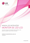
2.0kW/2.4kW/3.0kW Bare Bulb Replacement
Instruction Sheet
NOTICE: These instructions are for the relamping of the following lamp modules only.
Bulb Type
2.0kW
2.4kW
3.0kW
Non-RoHS
03-000887-01P
03-000883-01P
003-000305
RoHS
003-000746-01
003-000744-01
003-000305-02
INTRODUCTION
Use the following instructions when replacing the 2.0kW, 2.4kW and 3.0kW Xenon bulb in an existing
lamp module or new lamp house. This procedure involves disassembling the lamp house and replacing
the bulb inside. The entire lamp replacement procedure takes approximately one hour to complete.
Bare bulb replacement must be performed using the Christie approved
relamping jig (#38-804900-01). This jig is critical for lamp alignment. A lamp that is not properly
aligned can lower the brightness performance of the projector and cause overheating.
Complete all instructions carefully.
NOTE: Please refer to the Christie Website for detailed information regarding the Bare Bulb
warranty. Follow all instructions and warnings carefully. The warranty becomes void if the bulbs are
installed incorrectly.
2.0kW/2.4kW/3.0kW Bare Bulb Replacement Instruction Sheet
020-100908-01 Rev. 1 (05-2012)
1 of 15
WARNINGS
Lamp Replacement must be performed by QUALIFIED service personnel ONLY.
CAREFULLY READ ALL INSTRUCTIONS BEFORE HANDLING.
Power down the projector and allow the cooling fans to automatically turn off. Then
turn the main power switch OFF and unplug the projector. Allow the projector to cool for at
least 15 minutes.
This relamp procedure must be performed in a SECURE location with
CONTROLLED ACCESS ONLY.
DANGER – SEVERE EXPLOSION HAZARD! The Xenon bulb consists of tungsten
electrodes and a quartz envelope and is under very high pressure. Use extreme caution
when handling bulbs.
DANGER – SEVERE EXPLOSION HAZARD! Wear an Authorized FULL FACE
SHIELD to protect eyes and carotid artery and wear Authorized Protective Clothing during
this procedure.
NEVER TOUCH the quartz bulb with your bare hands. This will leave oil deposits
that react with the quartz when heated and greatly increases the risk of explosion during
use. If contaminated, clean with Isopropyl Alcohol only. Always wear latex gloves when
handling a new lamp.
HIGH VOLTAGES – follow all wiring instructions EXACTLY.
2 of 15
2.0kW/2.4kW/3.0kW Bare Bulb Replacement Instruction Sheet
020-100908-01 Rev. 1 (05-2012)
KITS REQUIRED
Ensure the following components are available:
• Re-Lamping Jig Kit #38-804900-01, includes:
• Jig base plate
• XYZ alignment stage
• Three screws (to secure alignment stage to jig base)
• Instructions
• Bare Bulb Replacement Kit (see Page 1 for Part# details) includes:
• Xenon bulb
• Intake air filter
• Instructions
• Protective Clothing Safety Kit #598900-095, includes:
• Jacket
• Face shield
• Gloves
TOOLS REQUIRED
•
•
•
•
•
#2 Phillips screwdriver
#1 Phillips screwdriver with right angle drive
2.5mm Allen key
3mm Allen key
5mm Allen key
2.0kW/2.4kW/3.0kW Bare Bulb Replacement Instruction Sheet
020-100908-01 Rev. 1 (05-2012)
3 of 15
INSTRUCTIONS
READ ALL INSTRUCTIONS BEFORE PROCEEDING.
Never attempt to remove the lamp immediately after use. The lamp is under
increased pressure when hot and may explode, causing personal injury and/or property
damage. Allow the lamp to cool completely before proceeding.
1. Power down the projector and allow the cooling fans to automatically turn OFF.
2. Turn the main power switch OFF and unplug. Allow the lamp to cool for at least 15 minutes after
the projector is turned OFF.
3. Use a #2 Phillips screwdriver to loosen the ¼-turn lock screws (2) securing the lamp door.
4. Remove the two screws securing the retaining bar along the bottom edge of the lamp module
(Figure 1 - Open Lamp Door and Remove Retaining Bar1).
Figure 1 - Open Lamp Door and Remove Retaining Bar
5. To remove the lamp module, grasp the handle on the lamp module and pull straight out (Figure 2 Remove Lamp Module2).
Figure 2 - Remove Lamp Module
4 of 15
2.0kW/2.4kW/3.0kW Bare Bulb Replacement Instruction Sheet
020-100908-01 Rev. 1 (05-2012)
6. Move the lamp module to a clean work surface for further disassembly.
Put on the protective jacket, face shield and gloves provided in kit #598900095.
NOTES: 1) Christie’s protective clothing recommendations are subject to change. 2) Any local or
Federal specifications take precedence over Christie recommendations.
7. Remove the nine screws securing the front cover of the lamp module (Figure 3 – Remove Lamp
Cover-2.0/2.4kW3-2.0/2.4kW or Figure 4 – Remove Lamp Cover-3.0kW4-3kW) and carefully lift
the front cover off of the lamp module.
Figure 3 – Remove Lamp Cover-2.0/2.4kW
Figure 4 – Remove Lamp Cover-3.0kW
2.0kW/2.4kW/3.0kW Bare Bulb Replacement Instruction Sheet
020-100908-01 Rev. 1 (05-2012)
5 of 15
8. Place the lamp house on the jig with the reflector side (front) facing the alignment pattern on the
jig as shown in Figure 5 – Place Lamp in Jig5.
Figure 5 – Place Lamp in Jig
9. Slide the lamp house along the base of the alignment jig until it connects with the dowel pins
(Figure 6 - Lamp Aligns with Jig6).
NOTE: The alignment jig used to replace a 2.0kW or a 2.4 kW bulb, has two dowel pins alignment
block (Figure 6 - Lamp Aligns with Jig6-Left). When replacing a 3.0kW bulb, the alignment block has
only one dowel pin (Figure 6 - Lamp Aligns with Jig6-Right). To simplify the procedure where the
Alignment Jig will be used for all three bulb types, you should replace the 2-pin alignment block with
the 1-pin alignment block. The new 1-pin alignment block (p/n 011-101190-01) can be used for the
replacement of all three bulb types.
Figure 6 - Lamp Aligns with Jig
6 of 15
2.0kW/2.4kW/3.0kW Bare Bulb Replacement Instruction Sheet
020-100908-01 Rev. 1 (05-2012)
10. Lower the clamp on the jig to secure the lamp house (Figure 7 - Lock-down Clamp7).
Figure 7 - Lock-down Clamp
NOTE: If you are using an older Alignment Jig you must include the following steps:
11. Remove the front screw on the XYZ stage (Figure 8 – Install XYZ Stage8). If the front screw is
not removed when installing the XYZ stage it interferes with the plastic lamp air duct on the lamp
module.
12. Install the XYZ stage onto the dowel pins at the back of the lamp (Figure 8 – Install XYZ Stage8).
Adjust the XYZ stage to ensure it does not push on the lamp. Tighten the locking screws.
Figure 8 – Install XYZ Stage
2.0kW/2.4kW/3.0kW Bare Bulb Replacement Instruction Sheet
020-100908-01 Rev. 1 (05-2012)
7 of 15
13. Adjust the XYZ stage until the three guidance holes at the back of the lamp connector are lined up
(Figure 9 – Adjust XYZ Stage9) and then install the three screws provided.
Figure 9 – Adjust XYZ Stage
14. From the front of the lamp module, remove the single screw securing the anode lead (Figure 10 Disconnect Anode Lead10).
Figure 10 - Disconnect Anode Lead
15. Slip the plastic protective sleeve over the bulb and secure it using the two ties. NOTE: You MUST
use the plastic protective sleeve in which the bulb was originally wrapped.
8 of 15
2.0kW/2.4kW/3.0kW Bare Bulb Replacement Instruction Sheet
020-100908-01 Rev. 1 (05-2012)
16. Holding the bulb from the front, unscrew and remove the lock nut securing it at the back (11).
Carefully and slowly, remove the bulb from the front of the lamp housing. Note: The Anode lead
is attached to the bulb.
Figure 11 - Remove Old Bulb
17. IMMEDIATELY place the bulb (with protective plastic sleeve attached) in the protective
clamshell case in which the bulb was shipped. IMPORTANT: DO NOT DISPOSE OF BULBS IN
THE TRASH. For more information, refer to theRemove
Bulb Old
Disposal
Lock NutInstructions, at the end of this
document.
NEVER TOUCH the quartz bulb with your BARE HANDS. Doing so will leave oil
deposits that react with the quartz when heated, which greatly increases the risk of explosion
during use. Always wear latex gloves when handling a new lamp. Should contamination occur,
you MUST replace the bulb immediately and dispose of the contaminated bulb as prescribed in
the Bulb Disposal Instructions at the end of this document.
18. Record the serial number of the new bulb onto the “Replacement Times” label on the top of the
lamp cover (12). NOTE: The serial number is required for warranty claims.
Figure 12 - Record Bulb Serial Number
2.0kW/2.4kW/3.0kW Bare Bulb Replacement Instruction Sheet
020-100908-01 Rev. 1 (05-2012)
9 of 15
19. Remove the new bulb from its protective clamshell case leaving the protective plastic cover
attached.
20. Untie the cathode end of the protective plastic sleeve covering the bulb and insert the bulb into the
lamp house through the opening at the front (reflector side). IMPORTANT: Avoid contact with the
reflector.
21. Ensure the bulb is positioned with the fill tube pointing down, as viewed from the front of the lamp
house (approximately the 7 o’clock angle to match the angle of the anode lead connection). See
13. IMPORTANT: If the bulb is incorrectly positioned it can reduce lamp life and image
uniformity and may result in Lamp Filcker.
Fill Tube
7 o’clock
Figure 13 - Fill Tube Position
22. Secure the new bulb to the lamp house using the new lock nut included in the new bulb kit (14).
DO NOT APPLY FORCE to the front of the bulb when tightening the lock nut.
Figure 14 - New Lock Nut
10 of 15
2.0kW/2.4kW/3.0kW Bare Bulb Replacement Instruction Sheet
020-100908-01 Rev. 1 (05-2012)
23. Secure the anode lead to the side of the lamp house, ensuring it hangs at approximately a 7 o’clock
angle from the lamp (viewed from the front) and is ¾” from the reflector edge (15).
Ensure the anode lead does not apply force onto the bulb.
Figure 15 – Secure Anode
24. Remove the plastic sleeve from the bulb.
Bare bulb replacement must be performed using the Christie approved relamping jig (#38-804900-01). This jig is critical for lamp alignment. A lamp that is not properly
aligned can lower the brightness of the projector and cause overheating. Follow all instructions
carefully.
2.0kW/2.4kW/3.0kW Bare Bulb Replacement Instruction Sheet
020-100908-01 Rev. 1 (05-2012)
11 of 15
25. Loosen the 19 screws on the lamp mount for XYZ adjustment (16).
Figure 16 – Loosen Screws
26. Looking through the small holes on the top and side of the reflector, adjust the lamp using the
knobs on the XYZ stage until the crosshair axis is centered on the anode and cathode electrode
(17). NOTE: If the view seems obstructed check that the anode lead is not in the path of the
alignment pattern on the bracket opposite the lamp.
Figure 17 – Align Lamp
12 of 15
2.0kW/2.4kW/3.0kW Bare Bulb Replacement Instruction Sheet
020-100908-01 Rev. 1 (05-2012)
27. With the lamp correctly positioned, tighten the 19 screws on the lamp mount. For more
information, refer to 16. Ensure lamp alignment does not change when tightening the screws on
the lamp mount.
28. Loosen the three Z-axis screws (18).
Figure 18 – Loosen Z-axis Screws
29. Adjust the Z-axis adjustment screw to center the crosshairs between the two electrodes.
30. When adjustment is complete, carefully tighten the three Z-axis screws, ensuring the position does
not change.
31. Record the serial number and enter it in the Lamp Menu the next time the projector is powered up.
32. Disengage the Lock-down Clamp and remove the Lamp House from the Alignment Jig.
33. Replace the Lamp House cover removed in Step 7.
LAMP INSTALLATION
34. Align the base plate of the new lamp module under both side alignment guides (19) and slide the
module entirely into the projector. Push with normal force until the resistance increases, then
firmly push module another ½ inch. NOTE: The lamp module must make full-contact with the
lamp connectors. Increased resistance indicates initial contact with the connectors – push firmly
at this point.
Figure 19 – Alignment Guides
Improper installation could cause a serious meltdown inside the projector.
2.0kW/2.4kW/3.0kW Bare Bulb Replacement Instruction Sheet
020-100908-01 Rev. 1 (05-2012)
13 of 15
35. Position the retaining bar along the bottom edge of the lamp module, with the ends positioned
under the alignment guides (Figure 20 – Install Retaining Bar20). If the bar does not fit, push the
lamp module further in. IMPORTANT: The order in which the screws are tightened is critical to
proper lamp contact alignment.
• Secure screw B until just engaged
• Secure screw A until just engaged
• Go back and forth between A and B to lock the bar in place with even pressure and correctly
position the lamp module
Figure 20 – Install Retaining Bar
36. Close the lamp door and tighten the two screws to secure it.
REPLACING THE AIR FILTER
It is recommended the air filter be replaced every 1000 hours or sooner if operating in dusty
environments. For more information, refer to the instructions outlined in the manual provided with the
projector.
BULB DISPOSAL INSTRUCTIONS
NOTE: On returns the RMA claim must accompany the bulb.
With the old bulb wrapped in a protective plastic sleeve, place it in the plastic case in which the new
bulb was shipped.
14 of 15
2.0kW/2.4kW/3.0kW Bare Bulb Replacement Instruction Sheet
020-100908-01 Rev. 1 (05-2012)
For warranty claims carefully re-pack the bulb with the original shipping material (including the
carton), enclose the completed RMA Claim Form that came with the bulb and ship it to the nearest
CDS service depot for evaluation.
The bulb is extremely hazardous. Do not dispose of in regular trash.
For safe disposal pack the bulb (with protective sleeve and case) into the original carton (without
packing material). Tape the box up securely along its seams. Drop it flat from at least 4-5 feet, so the
bulb breaks within the box. Shake to confirm. Discard as industrial waste according to local
regulations.
If you have any questions regarding this or any Christie product technical documentation, please
contact Technical Support at:
• NORTH AMERICA - +1-800-221-8025 or via email at: [email protected]
• EMEA - +44 (0) 1189 778111 or via email at: [email protected]
• AP - via email at: [email protected]
2.0kW/2.4kW/3.0kW Bare Bulb Replacement Instruction Sheet
020-100908-01 Rev. 1 (05-2012)
15 of 15