1
8514-027-003J
10/09
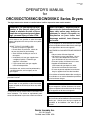
OPERATOR’S MANUAL
for
DRC55/DCTD55KC/DCWD55KC Series Dryers
The dryer must not be stored or installed where it will be exposed to water and/or weather.
WARNING: For your safety the information in this manual must be followed to minimize the risk of fire or
explosion or to prevent property damage, personal injury or loss of life.
Do not store or use gasoline or other flammable
vapors and liquids in the vicinity of this or any other
appliance.
– WHAT TO DO IF YOU SMELL GAS
• Do not try to light any appliance.
• Do not touch any electrical switch; do
not use any phone in your building.
• Clear the room, building or area of all
occupants.
• Immediately call your gas supplier from
a neighbor’s phone. Follow the gas
supplier’s instructions.
• If you cannot reach your gas supplier,
call the fire department.
– Installation and service must be performed by
a qualified installer, service agency or the
gas supplier.
Post the following “For Your Safety” caution in a
prominent location:
FOR YOUR SAFETY
Do not store or use gasoline or other flammable
vapors or liquids in the vicinity of this or any other
appliance.
It is important that you read this Manual and retain it for
future reference. For service or replacement parts,
contact the distributor in your area or the manufacturer.
AVERTISSEMENT. Assurez-vouz de
bien suivre les instructions données
dans cette notice pour réduire au
minimum le risque d'incendie ou
d'explosion ou pour éviter tout
dommage matérial, toute blessure
ou la mort.
Ne pas entreposer ni utiliser d'essence ni d'autres
vapeurs ou liquides inflammables dans le voisinage
de cet appareil ou de tout autre appareil.
– QUE FAIRE SI VOUS SENTEZ UNE ODEUR DE
GAZ:
• Ne pas tenter d'allumer d'appareil.
• Ne touchez à aucun interrupteur. Ne pas
vous servir des téléphones se trouvant
dans le bâtiment où vous vous trouvez.
• Évacuez la pièce, le bâtiment ou la zone.
• Appelez immédiatement votre
fournisseour de gaz depuis un voisin.
Suivez les instructions du fournisseur.
• Si vous ne pouvez rejoindre le fournisseur
de gaz, appelez le service des incendies.
– L'installation et l'entretien doivent être assurés par
un installateur ou un service d'entretien qualifié ou
par le fournisseur de gaz.
POUR VOTRE SÉCURITÉ
Ne pas enteposer ni utiliser d'essence ni d'autres
vapeurs ou liquides inflammables dans le voisinage
de cet appareil ou de tout autre appareil.
You, the purchaser, must post in a prominent location instructions to be followed in the event the user
smells gas. Consult your local gas supplier for
procedure to be followed if the odor of gas is
present.
Dexter Laundry, Inc.
2211 W. Grimes
Fairfield, Iowa 52556 USA
TABLE OF CONTENTS
PAGE NO.
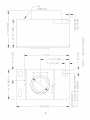
DRYER DIMENSIONS (Figure 1) ........................................................................ .3
UNCRATING ......................................................................................................... 4
DRYER INSTALLATION ....................................................................................... 4
DRYER EXHAUST SYSTEM (Figure 2) ...............................................................6
DRYER SHUTDOWN ........................................................................................... 7
OPERATING INSTRUCTIONS ............................................................................. 8
PROGRAMMING INSTRUCTIONS ......................................................... 9, 10, 11
SERVICING DRYER ........................................................................................... 15
PREVENTATIVE MAINTENANCE ..................................................................... 15
WARNINGS ABOUT USE AND OPERATION
It is ABSOLUTELY ESSENTIAL that the dryer be grounded to a known earth (zero) ground. This is not only for
personal safety, but is necessary for proper operation of the controller. Failure to do so will void the warranty of the
controller.
KEEP SHIELDS, GUARDS AND COVERS IN PLACE. These safety devices are provided to protect everyone
from injury.
A DRYER SHOULD BE CONNECTED TO POWER FOR THREE (3) MINUTES before it is operated or before a
program change is made. Operation or program changes, which occur during this “power up” period, are subject to
loss in case of power interruption. After the initial three minutes, all programmed data is protected from power
interruptions of any length and the customer’s individual cycle is protected up to 3 seconds. This is done without
batteries.
LEAVE THE ELECTRICAL POWER TO THE DRYER ON AT ALL TIMES except when necessary for service or
other similar activities. The hour meter function adds only full hours to its reading. If the power is shut off every night,
any fraction of an hour of time that is on the machine at that time will be lost. Turning the power off every night could
also have some effect on the long-term life of the memory after a number of years. Turning power off occasionally
won’t affect the unit.
THIS DRYER IS EQUIPPED WITH AN OVER-TEMPERATURE THERMOSTAT located on the right side of the lint
hood assembly (open lower service door). Should the dryer cease to operate, refer to your “Service Procedure and
Parts Data” book for instructions.
CHECK THIS THERMOSTAT WHEN INSTALLING DRYER to assure it is not tripped. Impacts such as rough
handling in shipment, may trip the thermostat.
2
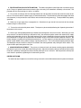
INSTALLATION AND OPERATING INSTRUCTIONS
COMMERCIAL DRYER
UNCRATING
1. Remove cardboard container and innerpack.
2. Complete the uncrating as described in the procedure listed on the instruction sheet taped to the loading door
glass.
DRYER INSTALLATION
1. CODE CONFORMITY. All commercial dryer installations must conform with local codes or, in the absence of
local codes, with the latest edition of the National Fuel Gas Code ANSI Z223. 1. Canadian installations must comply
with current Standard CAN/CGA-B149 (.1 or .2) Installation Code for Gas Burning Appliances or Equipment, and
local codes if applicable. The appliance, when installed, must be electrically grounded in accordance with the latest
edition of the National Electric Code, ANSI/NFPA70, or, when installed in Canada, with Standard CSA C22.1
Canadian Electrical Code Part 1.
2. INSTALLATION CLEARANCES: This unit may be installed at the following alcove clearance. (millimeter)
I.
Left Side
0"
II. Right Side 0"*
III. Back
18" (457) (Certified for 1" (25) clearance; however, 18" (457) clearance is necessary behind the
belt guard to allow servicing and maintenance.)
IV. Front
48" (1220) (to allow use of dryer)
V. Top
Refer to figure labeled “Vertical Clearance Dimensions”.
AB. Certification allows 0" clearance at the top 1" (25) back from the front. However, a 1/4" (6)
clearance is required to allow opening the upper service door.
CD. A 4" (102) clearance is required at the top between 1" (25) and 4" (102) from front.
E. A 10" (254) clearance is required from top at all other points.
VI. Floor
This unit may be installed upon a combustible floor.
*Units may be installed in direct contact with an adjacent dryer, providing allowance is made for opening upper
and lower service doors.
Do not obstruct the flow of combustion and ventilation air.
Maintain minimum of 1" (25) clearance between duct and combustible material.
Refer to installation label attached to the inside surface of the upper door of the dryer for other installation
information.
4
3. MAKE-UP AIR. Adequate make-up air (910 CFM) must be supplied to replace air exhausted by dryers on
all types of installations. Provide a minimum of 1.25 square feet of make-up air opening to the outside for each dryer.
This is a net requirement of effective area. Screens, grills or louvers, which will restrict the flow of air, must be
considered. Consult the supplier to determine the free area equivalent for the grill being used.
The source of make-up air should be located sufficiently away from the dryers to allow an even airflow to the air
intakes of all dryers. Multiple openings should be provided.
NOTE: The following considerations must be observed for gas dryer installations where dry cleaners are
installed. The sources of all make-up air and room ventilation air movement to all dryers must be located away
from any dry cleaners. This is necessary so that solvent vapors will not be drawn into the dryer inlet ducts.
Dry cleaner solvent vapors will decompose in contact with an open flame such as the gas flame present in
clothes dryers. The decomposition products are highly corrosive and will cause damage to the dryer(s), ducts
and clothes loads.
4. ELECTRICAL REQUIREMENTS. The electrical power requirements necessary to operate the unit satisfactorily are listed on the serial plate located on the back panel of each dryer. The electrical connection should be made
to the pig tail leads in the outlet box (or terminal board, if supplied) on the rear of the unit, using a wire size adequate
to handle the amperage and voltage listed on the serial plate, but never smaller than No.12 AWG wire. It is absolutely
necessary that the dryer be grounded to a known ground.
Individual circuit breakers for each unit are recommended. The schematic and wiring diagram are located on the
belt guard on the back of the machine.
5. GAS REQUIREMENTS. The complete gas requirements necessary to operate the dryer satisfactorily are
listed on the serial plate located on the back panel of the dryer.
The inlet gas connection to the unit is 1/2-inch pipe thred.
A joint compound resistant to the action of liquefied petroleum gases should be employed in making pipe
connections.
A 1/8-inch NPT plugged tapping, accessible for test gage connection, must be installed immediately upstream of
the gas supply connection to the dryer.
A drip tee should be provided in the gas piping entering the unit to catch dirt and other foreign articles.
All pipe connections should be checked for leakage with soap solution. Never check with an open flame.
For altitudes above 2,000 feet (610m) it is necessary to derate the BTU input. Contact your local distributor for
instructions.
L.P. gas conversion kits are available for this dryer. Contact your local distributor.
6. PRESSURE TESTING. The dryer and its individual shutoff valve must be disconnected from the gas supply
piping system during any pressure testing of that system at test pressures in excess of 1/2 psig. The dryer must be
isolated from the gas supply piping system by closing its individual manual shutoff valve during any pressure testing
of the gas supply piping system at test pressures equal to or less than 1/2 psig.
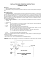
7. EXHAUST INSTALLATION. (Refer to Figure 2 at the end of section 7.) Exhausting of the dryer(s) should
be planned and constructed so that no air restrictions occur. Any restriction due to pipe size or type of installation
can cause slow drying time, excessive heat, and lint in the room.
From an operational standpoint, incorrect or inadequate exhausting can cause a cycling of the high limit thermostat,
which shuts off the main burners and results in inefficient drying.
Individual exhausting of the dryers is recommended. All heat, moisture, and lint should be exhausted outside by
attaching a pipe of the proper diameter to the dryer adapter collar and extending it out through an outside wall. This
pipe must be very smooth on the inside, as rough surfaces tend to collect lint, which will eventually clog the duct and
prevent the dryer from exhausting properly. All elbows must be smooth on the inside. All joints must be made so the
exhaust end of one pipe is inside the next one downstream. The addition of an exhaust pipe tends to reduce the
amount of air the blower can exhaust. This does not affect the dryer operation if held within practical limits. For the
most efficient operation, it is recommended that no more than 20 feet (6m) of straight 8" diameter pipe be used with
two right angle elbows. When more than two elbows are used, two feet of straight pipe should be removed for each
additional elbow. No more than four right angle elbows should be used to exhaust a dryer.
5
Maintain minimum of 1" (25) clearance between duct and combustible material.
If the exhaust pipe passes through a wall, a metal sleeve of slightly larger diameter should be set in the wall and
the exhaust pipe passed through this sleeve. This practice is required by some local codes and is recommended in
all cases to protect the wall. This type of installation should have a means provided to prevent rain and high winds
from entering the exhaust when the dryer is not in use. A hood with a hinged damper can be used for this purpose.
Another method would be to point the outlet end of the pipe downward to prevent entrance of wind and rain. In either
case, the outlet should be kept clear, by at least 24" (610), of any objects, which would cause an air restriction.
Never install a protective screen over the exhaust outlet.
When exhausting a dryer straight up through a roof, the overall length of the duct has the same limits as exhausting
through a wall. A rain cap must be placed on top of the exhaust and must be of such a type as to be free from clogging.
The type using a cone shaped “roof” over the pipe is suitable for this application.
Exhausting the dryer into a chimney or under a building is not permitted. In either case there is a danger of lint
build-up, which can be highly combustible.
Installation of several dryers where a main discharge duct is necessary, will need the following considerations for
installation (see Fig. 2). Individual 8" ducts from the dryers into the main discharge duct should be at a 45 degree angle
in the direction of discharge airflow.
NOTE: Never install the individual 8" ducts at a right angle into the main discharge duct. The individual ducts
from the dryers can enter at the sides or bottom of the main discharge duct. Figure 2 indicates the various
round main duct diameter to use with the individual dryer ducts. The main duct can be rectangular or round,
provided adequate airflow is maintained. For each individual dryer, the total exhausting (main discharge duct
plus duct outlet from the dryer) should not exceed the equivalent of 20 feet (6m) and two elbows. The diameter
of the main discharge duct at the last dryer must be maintained to exhaust end.
NOTE: A small diameter duct will restrict airflow; a large diameter duct will reduce air velocity -- both
contributing to lint buildup. An inspection door should be provided for periodic clean-out of the main duct.
DUCTS MUST ENTER
AT A 45° ANGLE
Figure 2 – Dryer Exhausting Using A Main Discharge Duct.
6
INSTALL
NO SCREEN
OR COVER
8. DRYER IGNITION (SOLID STATE IGNITION). The solid-state ignition system lights the main burner gas by
spark. The gas is ignited and burns only when the gas-valve relay (in the electronic controller) calls for heat. The
procedure for first-time starting of a dryer is as follows:
A. First, review and comply with the “Warnings About Use and Operation” found on the inside front cover of this
manual. Be sure the electrical power supply is connected correctly. The white wire is to be connected to the white
wire (common) in the junction box and the black wire to the black wire (power leg). The dryer MUST be properly
grounded.
B. Make sure all gas supply lines are purged of air. Close the main gas shut-off valve and wait for five minutes
before turning the valve back on.
C. Turn on the main electrical power switch. The dryer may be started by following the “Operating Instructions”
found later in this manual.
D. Natural gas and liquefied petroleum gas fired dryers both operate in the same manner. When the gas-valve
relay contacts are closed (indicating a demand for heat), the solid-state ignition control will automatically supply
energy to the redundant gas valve. Spark will continue until a flame is detected by the sensing probe, but not longer
than 10 seconds. If the gas fails to ignite within 10 seconds, the gas valve closes and the system will “lock out”. No
further attempts at ignition will be performed automatically. It is then necessary to interrupt electrical power to the
ignition system before making another attempt at igniting the burners. This can be done by opening the dryer door
and allowing the dryer to come to a stop for 15 seconds, then closing the door and pushing the “Start” button. The
dryer will then repeat the ignition trial cycle.
9. MAIN BURNER ADJUSTMENT. The primary air shutter of each main burner must be properly adjusted for
the correct air-gas ratio. Loosen the shutter locking screws. Adjust the shutter by closing it sufficiently to give a blue
flame with a yellow tip. Next open the shutter until the yellow tips are at a minimum. After adjustment, securely lock
each shutter in position by tightening the shutter locking screws.
DRYER SHUTDOWN
To render the dryer inoperative, turn off the main gas shut-off valve and disconnect electrical power to the dryer.
7
OPERATING INSTRUCTIONS
1. Deposit coins, tokens, or debit card to
satisfy vend price display of idle dryer.
Each deposit decreases vend price until
display changes to show time purchased.
WARM or LOW light illuminates.
•
•
•
•
•
•
•
•
•
•
•
•
•
•
VEND PRICE
2. Select drying cycle. Other cycle selections may be made now or later by pressing
the appropriate key (button).
3. Close the loading door. Press START and
the dryer will start. “Seconds” goes to
.
“Minutes” is rounded up and will count
down each minute. The colon flashes on
and off indicating the timer is counting
down.
•
•
•
•
MINUTES : SECONDS
PURCHASED
•
•
•
•
•
•
•
•
•
•
START
4. Clothes should be removed promptly after
the cycle is completed to prevent excessive wrinkling.
Once started, the “timer” cannot be stopped. However, extra coins will be acknowledged by adding time to the
display. The dryer may be stopped by opening the loading door, which interrupts the drive motor and gas burners.
Close the loading door and push
to restart the dryer.
START
Cool-down time (owner programmable) is always part of the cycle time and is purchased by the customer. For
example, if cool-down time is 2 minutes, the last 2 minutes of the cycle will have no heat.
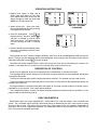
DESCRIPTION OF CONTROLS
Credit for coins deposited, dryer time and temperature are controlled by an electronic controller.
The large digital display shows vend price of an idle dryer, time purchased after coins are deposited, temperature
and program information.
The three red indicator lights show the drying temperature selected. This selection may be made anytime.
The drying temperature will be displayed when the start switch and the switch for the selected temperature are
pressed at the same time.
All programmed data is protected from power interruption of any length and the customer’s individual cycle is
protected for up to 3 seconds. This is done without batteries.
The 3 temperature buttons and the start button become programming switches when the controller is in the
program mode as described on page 10.
EASY CARD MODELS
Some Dexter dryers are factory equipped with a card reader that is used with Dexter’s Easy Card debit card
system. The card reader signals the dryer control when money is debited from the user’s card account to satisfy
the price of the dry time. The dryer’s pricing and the Easy Card system pricing are completely independent of
each other and must be programmed separately and coordinated. Refer to the instructions that came with the
Easy Card system for complete information.
8
PROGRAMMING:
(Instructions on Page 10 and 11)
All operating parameters (vend price, temperatures, cool-down times, etc.) are adjustable. In addition, several
displays of information are available from the controller (Money audits, hours run, dryer temperature).
The dryer is ready to run, from the factory, with the following pre-programmed data:
175 (degrees F) / 78 (degrees C)
150 (degrees F) / 63 (degrees C)
125 (degrees F) / 48 (degrees C)
25 (cents)
3:20 (3 minutes, 20 seconds for a dime)
(doesn’t apply to single-coin models)
Time for Right Coin:
8:00 (8 minutes for a quarter)
Time of Free Vend:
8:00 ("Free Dry" cycle is 8 minutes)
Cool-down Time, HOT or HIGH:
2:00 (Cool-down time in HOT or HIGH is 2 minutes)
Cool-down Time, MEDIUM:
2:00 (Same as above, except MEDIUM)
Cool-down Time, WARM or LOW: 2:00 (Same as above, except WARM or LOW)
Temperature Scale
F degrees
Decimal Point Display
ON
Seconds on Display
OFF
Temperature, HOT or HIGH:
Temperature, MEDIUM:
Temperature, WARM or LOW:
Vend Price:
Time for Left Coin:
All of the above data can be easily changed by the owner. The changes are made by the 4 keys or buttons on the
front of the control panel.
CHANGING PROGRAM DATA
Put dryer in PROGRAM mode as instructed on page 10. The dryer remains in the PROGRAM mode until one of
these actions occur:
• The switch is actuated again.
• The seventeenth step is completed and the START switch is pushed following the seventeenth step.
• Programming is stopped for about a minute.
• The loading door is closed.
Observe the displayed value in each step. If no change is required, press START to advance to the next program
step. If a change is required the values are made larger by the HOT or HIGH button, smaller by the MED button. The
hour meter and money audit can be reset to zero if WARM or LOW is pressed.
Note that after any reset or program change it is necessary to advance to the next step by pressing START to enter
the revision. OTHERWISE THE VALUE WILL REMAIN AS IT WAS BEFORE THE ALTERATION.
9
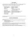
PROGRAMMING INSTRUCTIONS:
(To switch to program mode.)
SERVICE
DOOR
1. Unlock and open the upper service door.
2. Open the loading door.
3. Push the Program Button found just to the left of the
WARM or LOW cycle light. The Button is accessible
through a hole in control mounting plate, after removal
of bright metal plug.
4. The control switches to PROGRAM mode. In PROGRAM mode, the membrane switch keypad becomes
a 4-switch programming tool.
5. The ACTUAL NUMERICAL VALUES desired are keyed
in as explained on P.11.
PROGRAM
BUTTON
ANNUNCIATOR LIGHTS WHICH HELP
IDENTIFY PROGRAMMING STEPS
LOADING
DOOR
TYPE 2 PROGRAMMING
DISPLAY
INCREASES
DISPLAYED VALUES
DECREASES
DISPLAYED VALUES
START
ZEROS HOUR METER ON STEP 1
ZEROS COIN COUNT ON STEP 2
RESTORES ORIGINAL VALUE ON STEPS 3-14
HOT
OR
HIGH
PERM
MED.
PRESS
WARM OR
LOW
START
START: Stores the displayed value in memory,
and advances the controller to the
next programming step.
IMPORTANT: Please remember to push
to actually enter (store in memory) new data. If you merely change the
display, memory hasn’t yet been changed -- only START will actually change the memory!
START
10
11
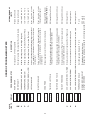
•
•
•
••
•
•
•
•
Median operating temp. - Medium (Permanent Press)
Median operating temp. - Warm or Low (Delicate)
TEMPERATURE; MEDIUM
TEMPERATURE; WARM or LOW
LEFT COIN VALUE
RIGHT COIN VALUE
VEND PRICE
TIME FOR LEFT COIN
TIME FOR RIGHT COIN
TIME OF FREE VEND
– – – –
– – – –
– – – –
– – – –
– – – –
– – – –
– – – –
– – – –
M
W
COOL-DOWN TIME; WARM or LOW Minutes and seconds of cool-down; Warm or Low cycle
– – – –
W
COOL-DOWN TIME; MEDIUM
– – – –
M
Sets Temperature Display to °F or °C
Displays decimal point in prices.
OFF or ON
Displays time remaining in minutes:00 or in minutes:seconds. OFF or ON
DISPLAY: DECIMAL POINT
DISPLAY: SECONDS
F or C
00 through 10 min
00 through 10 min
00 through 10 min
00 through 99 min: 55 sec
00 through 99 min: 55 sec
TEMPERATURE SCALE
Minutes and seconds of cool-down; Medium cycle
COOL-DOWN TIME; HOT or HIGH
– – – –
H
Minutes and seconds of cool-down; Hot or High cycle
Minutes and seconds of “Free” dry (If free dry feature is
used - see vend price above.)
Minutes and seconds awarded for one coin deposited
through the right coin acceptor (all models)
00 through 99 min: 55 sec
00 through 9999 (cents)
(00 causes “Free Vend”)
Money required to start the dryer in 1¢ increments.
Minutes and seconds awarded for one coin deposited
through the left coin acceptor (dual coin models)
Must be value of coins
through right acceptor
Must be value of coins
through left acceptor
110 - 150°F / 39 - 63°C
120 - 170°F / 45 - 75°C
150 - 190°F / 63 - 87°C
May be reset to zero
May be reset to zero
OPTIONS/RANGE OF
LIMITS
Value of coin/token deposited through right acceptor
(all models) in 1¢ increments. For Easy Card systems,
set to default.
Value of coin/token deposited through left acceptor (dual
coin models) in 1¢ increments. For Easy Card systems,
set to default.
Median operating temp. - Hot or High (Regular).
TEMPERATURE; HOT or HIGH
H
– – – –
Displays hours of “timer” operation
DESCRIPTION
Number of pulses from acceptor or Easy Card reader.
HOURMETER
PROGRAMMING STEP
MONEY AUDIT
DISPLAY
– – – –
H
M
W
CYCLE
LIGHTS
ORDER OF PROGRAMMING STEPS
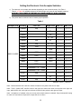
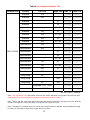
Setting the Electronic Coin Acceptor Switches
1) The electronic coin acceptor has switches depending on the coins and country. See Table 1,
Table 2, or Table 3 for available values of the left and right coin inputs for the available countries.
WARNING: TURN POWER OFF BEFORE AND LEAVE POWER OFF WHEN CHANGING
THE SWITCHES OF THE ELECTRONIC COIN ACCEPTOR.
2) Turn power back on and test coins to ensure proper operation.
Table 1
Acceptor P/N
Country
Left Coin
Canada
25¢
SWs 1-8
SWs 9-16
↓↓↑↑↑↑↑↓
↓↑↑↑↑↑↑↓
Canada
$1
↑↑↓↓↑↑↑↓
↓↑↑↑↑↑↑↓
Canada
$2
↑↑↑↑↓↓↓↓
↓↑↑↑↑↑↑↓
Canada
$1 + $2
↑↑↓↓↓↓↓↓
↓↑↑↑↑↑↑↓
Canada
25¢
$1
↓↓↓↓↑↑↑↓
↓↑↑↑↑↑↑↓
Canada
25¢
$1 + $2
↓↓↓↓↓↓↓↓
↓↑↑↑↑↑↑↓
Japan
100¥
↓↓↑↑↑↑↑↓
↑↓↑↑↑↑↑↓
500¥
↑↑↓↓↑↓↓↓
↑↓↑↑↑↑↑↓
500¥
↓↓↓↓↑↓↓↓
↑↓↑↑↑↑↑↓
↓↓↑↑↑↑↑↓
↑↑↓↑↑↑↑↓
50NT
↑↑↓↓↑↓↓↓
↑↑↓↑↑↑↑↓
50NT
↓↓↓↓↑↓↓↓
↑↑↓↑↑↑↑↓
Japan
9021-014-002
Right Coin
Japan
100¥
Taiwan
10NT
Taiwan
Taiwan
10NT
Korea
500W
↓↓↑↑↑↑↑↓
↑↑↑↓↑↑↑↓
Greenwald 118-1 Token
↑↑↑↑↑↑↑↓
↑↑↑↑↓↑↑↓
Greenwald 118-5 Token
↑↑↑↑↑↑↑↓
↑↑↑↑↑↓↑↓
25¢
↓↓↑↑↑↑↑↓
↑↑↑↑↑↑↓↓
$1
↑↑↓↓↑↑↑↓
↑↑↑↑↑↑↓↓
$1
↓↓↓↓↑↑↑↓
↑↑↑↑↑↑↓↓
U.S.A.
U.S.A.
U.S.A.
25¢
Switches ↑=up/on, ↓=down/off
Note: Coins and tokens in the left coin column will result in one pulse to the left coin input.
Note: The $1, 500¥, 50NT, and $10 coins in the right coin column will result in one pulse to the right coin
input, while the $2 coin in the right coin column will result in two pulses to the right coin input.
Note: Acceptance of multiple coins per country and multiple tokens is allowed. Only the down/off setting
for each coin and token is required to accept that coin or token.
12
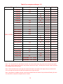
Table 2 for acceptors with spec 109
Acceptor P/N
9021-015-002
Country
Left Coin
Australia
Australia
Right Coin
SWs 1-8
SWs 9-16
10¢
↓↓↑↑↑↑↑↓
↑↓↑↑↑↑↑↓
20¢
↑↑↓↓↑↑↑↓
↑↓↑↑↑↑↑↓
Australia
$1
↑↑↑↑↓↓↑↓
↑↑↓↑↑↑↑↓
Australia
$2
↑↑↑↑↑↑↓↓
↓↑↓↑↑↑↑↓
Australia
$1 + $2
↑↑↑↑↓↓↓↓
↓↑↓↑↑↑↑↓
Australia
10¢
$1
↓↓↑↑↓↓↑↓
↑↓↓↑↑↑↑↓
Australia
10¢
$1 + $2
↓↓↑↑↓↓↓↓
↓↓↓↑↑↑↑↓
Australia
20¢
$1
↑↑↓↓↓↓↑↓
↑↓↓↑↑↑↑↓
Australia
20¢
$1 + $2
↑↑↓↓↓↓↓↓
↓↓↓↑↑↑↑↓
New Zealand
10¢
↓↓↑↑↑↑↑↓
↑↓↑↑↑↑↑↓
New Zealand
20¢
↑↑↓↓↑↑↑↓
↑↓↑↑↑↑↑↓
New Zealand
$1
↑↑↑↑↓↓↑↓
↑↑↑↓↑↑↑↓
New Zealand
$2
↑↑↑↑↑↑↓↓
↓↑↑↓↑↑↑↓
New Zealand
$1 + $2
↑↑↑↑↓↓↓↓
↓↑↑↓↑↑↑↓
New Zealand
10¢
$1
↓↓↑↑↓↓↑↓
↑↓↑↓↑↑↑↓
New Zealand
10¢
$1 + $2
↓↓↑↑↓↓↓↓
↓↓↑↓↑↑↑↓
New Zealand
20¢
$1
↑↑↓↓↓↓↑↓
↑↓↑↓↑↑↑↓
New Zealand
20¢
$1 + $2
↑↑↓↓↓↓↓↓
↓↓↑↓↑↑↑↓
Hong Kong
$5
↓↓↓↓↑↑↑↓
↑↑↑↑↓↑↑↓
$10
↑↑↑↑↓↓↑↓
↑↑↑↑↓↑↑↓
$10
↓↓↓↓↓↓↑↓
↑↑↑↑↓↑↑↓
Greenwald 118-1 Token
↑↑↑↑↑↑↑↓
↑↑↑↑↑↓↑↓
Greenwald 118-5 Token
↑↑↑↑↑↑↑↓
↑↑↑↑↑↑↓↓
Hong Kong
Hong Kong
$5
Switches ↑=up/on, ↓=down/off
Note: The 10¢ and $5 coins and tokens in the left coin column will result in one pulse to the left coin input,
while the 20¢ coins in the left column will result in two pulses to the left coin input.
Note: The $1 and $10 coins in the right coin column will result in one pulse to the right coin input, while the
$2 coin in the right coin column will result in two pulses to the right coin input.
Note: Acceptance of multiple coins per country and multiple tokens is allowed. Only the down/off setting
for each coin and token is required to accept that coin or token.
13
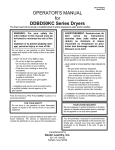
Table 3 for acceptors with spec 311
Acceptor P/N
9021-015-002
Country
Left Coin
Australia
Australia
Right Coin
SWs 1-8
SWs 9-16
10¢
↓↓↑↑↑↑↑↓
↑↑↓↑↑↑↑↑
20¢
↑↑↓↓↑↑↑↓
↑↑↓↑↑↑↑↑
Australia
$1
↑↑↑↑↓↓↑↓
↑↑↓↑↑↑↑↑
Australia
$2
↑↑↑↑↑↑↓↓
↓↑↓↑↑↑↑↑
Australia
$1 + $2
↑↑↑↑↓↓↓↓
↓↑↓↑↑↑↑↑
Australia
10¢
$1
↓↓↑↑↓↓↑↓
↑↑↓↑↑↑↑↑
Australia
10¢
$1 + $2
↓↓↑↑↓↓↓↓
↓↑↓↑↑↑↑↑
Australia
20¢
$1
↑↑↓↓↓↓↑↓
↑↑↓↑↑↑↑↑
Australia
20¢
$1 + $2
↑↑↓↓↓↓↓↓
↓↑↓↑↑↑↑↑
New Zealand
10¢
↓↓↑↑↑↑↑↓
↑↑↑↓↑↑↑↑
New Zealand
20¢
↑↑↓↓↑↑↑↓
↑↑↑↓↑↑↑↑
New Zealand
50¢
↑↑↑↑↑↑↑↓
↑↓↑↓↑↑↑↓
New Zealand
$1
↑↑↑↑↓↓↑↓
↑↑↑↓↑↑↑↑
New Zealand
$2
↑↑↑↑↑↑↓↓
↓↑↑↓↑↑↑↑
New Zealand
$1 + $2
↑↑↑↑↓↓↓↓
↓↑↑↓↑↑↑↑
New Zealand
10¢
$1
↓↓↑↑↓↓↑↓
↑↑↑↓↑↑↑↑
New Zealand
10¢
$1 + $2
↓↓↑↑↓↓↓↓
↓↑↑↓↑↑↑↑
New Zealand
20¢
$1
↑↑↓↓↓↓↑↓
↑↑↑↓↑↑↑↑
New Zealand
20¢
$1 + $2
↑↑↓↓↓↓↓↓
↓↑↑↓↑↑↑↑
Hong Kong
$5
↓↓↓↓↑↑↑↓
↑↑↑↑↓↑↑↑
$10
↑↑↑↑↓↓↑↓
↑↑↑↑↓↑↑↑
$10
↓↓↓↓↓↓↑↓
↑↑↑↑↓↑↑↑
Greenwald 118-1 Token
↑↑↑↑↑↑↑↓
↑↑↑↑↑↓↑↑
Greenwald 118-5 Token
↑↑↑↑↑↑↑↓
↑↑↑↑↑↑↓↑
Hong Kong
Hong Kong
$5
Switches ↑=up/on, ↓=down/off
Note: The 10¢ and $5 coins and tokens in the left coin column will result in one pulse to the left coin input, while
20¢ coins in the left column will result in two pulses to the left coin input. The 50¢ coin in the left column will result
in five pulses to the left coin input.
Note: The $1 and $10 coins in the right coin column will result in one pulse to the right coin input, while the $2
coin in the right coin column will result in two pulses to the right coin input.
Note: Acceptance of multiple coins per country and multiple tokens is allowed. Only the down/off setting for each
coin and token is required to accept that coin or token.
14
SERVICING THE DRYER
CAUTION: Label all wires prior to disconnection when servicing controls. Wiring errors can cause improper and
dangerous operation. Verify proper operation after servicing.
ATTENTION. Lors des opérations d'entretien des commandes, étiqueter tous les fils avant de les déconnecter.
Toute erreur de câblage peut être une source de danger et de panne.
PREVENTIVE MAINTENANCE INSTRUCTIONS
DAILY
1. Clean lint screen. Use soft brush if necessary.
2. Check lint screen for tears. Replace if necessary.
3. Clean lint from lint screen compartment.
MONTHLY
1. Remove lint accumulation from end bells of motor.
2. Remove lint from meter compartment and meter mechanism.
3. Remove lint and dirt accumulation from top of the dryer and all areas above, below and around the burners and
burner housing. Failure to keep this portion of the dryer clean can lead to a build-up of lint creating a fire hazard.
4. Place a few drops of light oil on clothes door hinge.
QUARTERLY
1. Check belts for looseness, wear or fraying.
2. Inspect gasket of door glass for excessive wear.
3. Check tightness of all fasteners holding parts to support channel.
4. Check tightness of all set screws.
5. Inspect impeller for tightness of blades to hub.
6. Check tightness of tumbler shaft retaining cap screw.
7. Remove back inspection plate and check tumbler thru-bolts for tightness.
8. Remove lint accumulation from primary air ports in burners.
9. Grease pivot pins and tension arms where in contact with each other.
10. Apply a few drops of oil to each spacer tube on the tension arm assembly.
SEMI-ANNUALLY
1. Remove and clean main burners.
2. Remove all orifices and examine for dirt and hole obstruction.
3. Remove all lint accumulation. Remove front panel, lint screen housing and remove lint accumulation.
ANNUALLY
1. Check intermediate pulley bearings for wear.
2. Check and remove any lint accumulation from exhaust system.
15