1
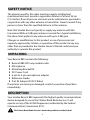
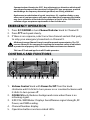
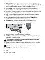
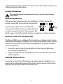
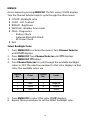
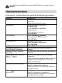
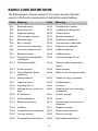
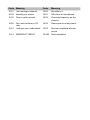
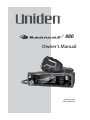
® 880 Owner’s Manual Printed in China U01UT390ZZA(0) Contents SAFETY NOTICE............................................................................ 4 Unpacking.................................................................................. 4 Description ............................................................................... 4 Emergency Operation ........................................................... 5 Controls and Functions...................................................... 5 Installation.............................................................................. 8 MOBILE INSTALLATION ............................................................................... 8 Mobile Antenna............................................................................................ 8 Connecting the Power Cords ....................................................................... 8 Ground Information .................................................................................... 9 Install 6-Pin to 4-Pin Adapter .............................................................. 9 MARINE INSTALLATION ............................................................................... 9 Using Your Bearcat 880....................................................... 10 CB MODE....................................................................................................... 10 Basic Settings......................................................................................... 10 All Channel Scan.................................................................................... 10 Weather Mode (WX mode)..................................................................... 11 Set Weather Scan Mode............................................................................. 11 Set Weather Alert Mode............................................................................. 12 MEMORY Mode........................................................................................... 12 Save Channels Into Memory...................................................................... 12 Scan Channels in Memory......................................................................... 12 Listen to Channels in Memory................................................................... 12 Clear Channels from Memory.................................................................... 12 MENUS.......................................................................................................... 13 Select Backlight Color................................................................................ 13 Set LCD Contrast........................................................................................ 14 Set Brightness............................................................................................ 14 Diagnostic Menus...................................................................................... 14 Antenna Mismatch Check.......................................................................... 15 RF Power Check.......................................................................................... 15 EXIT Menu................................................................................................... 15 Other Features........................................................................................ 15 S/RF/CAL/SWR Meter ................................................................................. 15 Calibrate Standing Wave Ratio (SWR) ...................................................... 16 Preventive Maintenance .................................................... 16 Maintenance .......................................................................... 16 Troubleshooting ................................................................. 17 Servicing Your Transceiver .............................................. 18 SpEcifications......................................................................... 18 Two-Year Extended Warranty ......................................... 19 Uniden is a registered trademark of Uniden America Corporation. Bearcat is a registered trademark of Uniden America Corporation. Features, specifications, and availability of optional accessories are all subject to change without notice. SAFETY NOTICE The antenna used for this radio must be properly installed and maintained and must provide a separation distance of at least 34 cm (13.4 Inches) from all persons and must not be collocated or operated in conjunction with any other antenna or transmitter. Never transmit if any person is closer than the specified distance to the antenna. Note that Uniden does not specify or supply any antenna with this transceiver. While a 0 dBi gain antenna is normal for a typical installation, the above limit applies to any antenna with up to 3 dBi gain. Changes or modifications to this product or use of accessories not expressly approved by Uniden, or operation of this product in any way other than as provided in the Uniden Owner’s Manual could void your authority to operate this product. Unpacking Your Bearcat 880 contains the following: Bearcat 880 CB 2-way mobile radio Microphone Mounting Bracket Kit DC Power Cord 6-pin to 4-pin microphone adapter Reference Guide Part 95 Subpart D (FCC Rules) If any items are missing or damaged, contact your place of purchase immediately. Description Your Uniden Bearcat 880 represents the highest quality communications device designed for use in the Citizens Band Radio Service. It will operate on any of the 40 AM frequencies authorized by the Federal Communications Commission (FCC). The Citizens Band Radio Service is under the jurisdiction of the Federal 4 Communications Commission (FCC). Any adjustments or alterations which would alter the performance of the transceiver's original FCC type acceptance, or which would change the frequency determining method, are strictly prohibited. Replacement or substitution of crystal, transistors, ICs, regulator diodes, or any other part of a unique nature, with parts other than those recommend by Uniden, may cause violations of the technical regulations in Part 95 of the FCC Rules or in violation of type acceptance requirements in Part 2 of the rules. Emergency Operation 1. Press 9/19/NORM or turn Channel Selector knob to Channel 9. 2. Press PTT and speak clearly. 3. If there is no response, select an active channel and ask that party to relay your emergency broadcast on Channel 9. All channels except Channel 9 may be used for normal communication. The FCC reserves Channel 9 for emergencies involving the immediate safety of individuals or protection of property. Use Channel 9 to render assistance to a motorist. This is an FCC rule and applies to all CB radio operators. Controls and Functions 1 2 7 8 9 3 4 5 6 10 11 12 13 14 15 16 1. Volume Control knob with Power On/Off. Turn the knob clockwise until it clicks to turn power on or counterclockwise until it clicks to turn power off. 2. SQUELCH knob: Reduces background noise when there is no incoming signal. 3. S/RF/CAL/SWR Meter: Displays Send/Receive signal strength, RF Power, and SWR reading. 4. Channel Number display. 5. Operation buttons and associated LEDs: 5 Talkback: Talkback lets you monitor yourself when transmitting. Press Talkback to activate the function (LED = on). With Talkback active, press PTT and adjust the volume with the Volume Control knob. (Levels 00 - 15) MIC Gain: Adjusts microphone sensitivity. Delivers up to 100% modulation. With MIC Gain active, press PTT and adjust the gain levels with the Volume Control knob. (Levels 00 - 04) If Talkback is on when MIC Gain is also on, Talkback volume increases. Weather: Press to toggle between Weather and CB channels. Turn Channel Selector to cycle through the 7 weather channels. (LED off = CB channels; LED on = Weather channels) Press and hold to turn Weather Alert on and off. ALERT displays. Day/Night: Adjusts LCD backlight sensitivity between Day and Night modes. (LED off = Day; LED on = Night) 6. Channel Selector/MENU/OK. Press the inner MENU/OK button to select a menu option or other selection. Turn the outer Channel Selector knob to: Select channels Select menu modes Change scan resume direction (up or down) Control Talkback volume Control Mic gain level Control Calibration volume All channels except Channel 9 may be used for normal communication. The FCC reserves Channel 9 for emergencies involving the immediate safety of individuals or protection of property. Use Channel 9 to render assistance to a motorist. This is an FCC rule and applies to all CB operators. 7. Microphone socket. 8. Indicators turn on when the function is turned on. 9. S/RF/CAL/SWR: Push to to check RF signal strength, calibration, and SWR reading. 10. CB/PA: Selects CB (Citizens Band) or PA (Public Address). Do not use the PA function unless an external speaker is connected. 6 11. MEM/SCAN: Press to start or stop scanning modes [All Channel Scan (see page 10) and Memory Scan (see page 12)]. Press and hold to set or clear channel memory while in Memory mode. 12. 9/19/NORM: Press to switch between emergency channel 9, channel 19, and standard CB channels. 13. Frequency Display: Displays the MHz of the selected channel. Also displays menu options. 14. ANL: Turns ANL (Automatic Noise Limiter) feature on and off. ANL reduces external noise. 15. NB: Turns NB (Noise Blanker) feature on and off. NB reduces interference from vehicle ignition systems. 16. RF Gain knob: Improves reception in strong signal areas. 17 18 19 22 20 21 17. Antenna socket: Connects antenna to the unit. 18. PA SP: Connects optional external 8-ohm, 4-watt speaker for use as a public address system. To prevent acoustic feedback, separate the microphone from the speaker when operating the PA at high output levels. 19. EXT. SP: Connects an 8-ohm 4-watt speaker to remotely monitor the receiver. When the external speaker is plugged in, the internal speaker is off. 20. POWER: Connects DC power to transceiver. 21. Fuse. 22. PTT: Push-to-Talk. 7 Installation MOBILE INSTALLATION Plan the location of the transceiver and microphone bracket before beginning installation. 1. Select a location that is convenient for operating the radio but does not interfere with the driver or passenger. 2. Install bracket with self-tapping screws provided. 3. Connect power cords (see page 8). 4. Attach the microphone bracket to side of the radio. 5. Attach radio to bracket. Mobile Antenna Because the maximum power output of the transmitter is limited by the FCC, the quality of your antenna is very important. To achieve the maximum transmission distance, Uniden strongly recommends that you install only a high quality antenna. You have just purchased a superior transceiver - don't diminish its performance by installing an inferior antenna. Only a properly matched antenna system will allow maximum power transfer from the 50 ohm transmission line to the radiating element. Your Uniden dealer is qualified to help you select the proper antenna for your requirements. A whip style antenna may be used for automobile installation. A short ‘loaded’ whip antenna is easier to install on an automobile, but its efficiency is less than that of a full quarter-wave whip antenna. Connecting the Power Cords Uniden recommends connecting the power lead to the Ignition Switch Accessory Terminal. This way, the transceiver is automatically turned off when the ignition switch is turned off. As an alternative, the power cord may be connected to an available terminal on the fuse block or to a point in the wiring harness. However, 8 caution must be taken to prevent a short circuit. If in doubt, contact your vehicle dealer for information. Ground Information This transceiver may be installed and used in any 12-volt DC negative ground system vehicle. Negative Ground System With a negative ground system, the negative (-) battery terminal is usually connected to the vehicle motor block. Connect the red DC power cord from the transceiver to the positive (+) battery terminal or other convenient point. Then connect the black power cord to the vehicle chassis or negative (-) battery terminal. Install 6-Pin to 4-Pin Adapter The Bearcat 880 is pre-configured for Uniden’s new 6-pin wireless, noisecancelling technology, available in 2012. Your Bearcat 880 comes with an adapter to connect the radio’s 6-pin microphone to a current standard 4-pin microphone. 1. Insert the 6-pin side of the adapter into the Bearcat 880 6-pin microphone connection. 2. Plug a standard 4-pin microphone connector into the 4-pin side of the adapter. MARINE INSTALLATION Consult your dealer for information regarding marine installation. It is important to adequately ground the system and to prevent electrolysis between the fittings in the hull and the water. 9 Using Your Bearcat 880 CB MODE Be sure that the power source, antenna, and microphone are properly connected before proceeding. Basic Settings 1. 2. 3. 4. • Turn unit on. Set volume to a comfortable level. Select channel. Set noise limitations as desired (ANL/NB). Adjust Squelch. Turn SQUELCH fully clockwise so only strong signals can get through. • Turn SQUELCH fully counterclockwise until you hear a hiss. Everything gets through - noise, weak signals, and strong signals • Turn SQUELCH back clockwise until the hiss stops. Only clearer signals get through. Set SQUELCH only when the radio is not receiving a strong signal. 6. 7. 8. 9. 5.Turn RF Gain to set RF gain sensitivity. Press MIC Gain to toggle microphone sensitivity between High and Low. (LED on = High; LED off = Low) Set Backlight color (see page 13). Set LCD Contrast (see page 14). Set Brightness (see page 14). All Channel Scan When All Channel Scan is on, the radio scans channels until it receives a signal. It will move to the next channel if no signal is received after 3 seconds. 1. Press MEM/SCAN once if in CB mode (twice if in MEM mode). SCAN displays. 2. The radio begins scanning upward through the channels. • To skip the channel the radio has stopped on, turn Channel Selector clockwise to move to the next channel or counterclockwise to move to the previous channel. The radio continues 10 scanning in the selected direction. • To change to Memory Channel Scan mode, press MEM/SCAN while in All Channel Scan mode (see page 12). 3. To exit All Channel Scan mode, press PTT, 9/19/NORM, WEATHER, or CB/PA. Weather Mode (WX mode) Your radio combines a CB radio with a Weather radio and a Weather Alert system. The Weather Alert system sounds a seven-second signal in the event of severe weather when you are in CB mode. The Weather radio continually broadcasts weather conditions when you are in Weather mode. 1. Press WEATHER. Your radio is now in Weather radio mode. 2. Select 1 of 7 weather channels using Channel Selector. You cannot change ANL or NB settings while in WX mode. The radio will sound an alert tone. Set Weather Scan Mode Weather Scan mode allows the radio to move to the next weather channel if no signal is detected after 3 seconds. Set Weather Scan mode to ON or OFF through the menus. 1. Press MENU/OK to activate the menus. COLOR displays. 2. Turn the Channel Selector knob to cycle through the menu options until WXSCAN displays. 3. Press MENU/OK. ON displays. 4. Press MENU/OK to set Weather Scan mode to ON or turn the selection knob until OFF displays and then press MENU/OK to set it. WXSCAN displays again. If Weather Scan is ON when you turn off the radio, it remains ON. Left at these setting (WX mode, WX Scan), you will hear only weather broadcasts and Weather Alert signals. To use your CB radio normally while monitoring weather alerts, press WEATHER again. 11 Set Weather Alert Mode Weather Alert mode only operates when you are in CB mode; it does not operate in Weather mode. In CB mode, the radio sounds an alert tone when it detects a 1050Hz tone on a weather channel. Press and hold WEATHER to turn Weather Alert on. The WEATHER LED turns on. MEMORY Mode You can select channels to store into memory and then scan only those channels. Save Channels Into Memory 1. 2. 3. 4. Tune to a channel in CB mode. Press and hold MEM/SCAN until SAVE appears (about 2 seconds). Release MEM/SCAN. The radio stays on the saved channel. Scan Channels in Memory 1. From All Channel Scan mode (see page 10), press MEM/SCAN until MEM SCAN displays; the radio scans memory channels only. 2. Press MEM/SCAN again to return to MEMORY mode or the last channel scanned. Listen to Channels in Memory 1. Press MEM/SCAN until MEM displays. 2. Turn the Channel Selector knob and only saved channels will be heard. Clear Channels from Memory 1. In MEM mode, select a channel. 2. Press and hold MEM/SCAN until CLEAR displays. 3. Release MEM/SCAN. The radio plays the next channel in memory. 12 MENUS Access menus by pressing MENU/OK. The first menu, COLOR, displays. Turn the Channel Selector knob to cycle through the other menus: COLOR - Backlight color CONT - LCD Contrast BRIGHT - Brightness WXSCAN - Weather Scan mode DIAG - Diagnostics –– Battery Check –– Antenna Mismatch Check –– RF Power Check Exit Select Backlight Color 1. Press MENU/OK to activate the menus. Turn Channel Selector until COLOR displays. 2. Press MENU/OK. Turn Channel Selector until DAY displays. 3. Press MENU/OK. DAY blinks. 4. Turn Channel Selector to cycle through the available backlight colors or OFF. The selection number for that color displays in that color. The available colors are: Option No: Color Option No: Color 0 None (Off ) 4 Red 1 Blue 5 Magenta 2 Green 6 Yellow 3 Cyan 7 White 5. Press MENU/OK to select that color. COLOR displays. 6. Repeat these procedures to set the NIGHT backlight color. 13 Set LCD Contrast 1. Press MENU/OK to activate the menus. Turn Channel Selector until CONT displays. 2. Press MENU/OK. Turn Channel Selector until DAY displays. 3. Press MENU/OK. DAY blinks. 4. Turn Channel Selector to cycle through the contrast options. (Lowest = 00; Highest = 15) 5. Press MENU/OK to select the one you want. CONT displays again. 6. Repeat these procedures to set the NIGHT contrast level. Set Brightness 1. Press MENU/OK to activate the menus. Turn Channel Selector until BRIGHT displays. 2. Press MENU/OK. DAY displays. 3. Press MENU/OK. DAY blinks. 4. Turn Channel Selector to cycle through the brightness options. (Lowest = 00; Highest = 15) 5. Press MENU/OK to select the one you want. BRIGHT displays again. 6. Repeat these procedures to set the NIGHT brightness level. Diagnostic Menus 1. Press MENU/OK to activate the menus. 2. Turn Channel Selector until DIAG displays. 3. Press MENU/OK to enter the DIAG level. From the DIAG level, you can check battery power levels, RF power levels, and antenna mismatch. Battery Check Check the DC power levels if you feel your radio is not performing properly. 1. Once DIAG displays, press MENU/OK; VOLT displays. 2. Press MENU/OK; the battery voltage displays for 2 seconds and then the battery voltage condition displays: –– PASS - Voltage is good. –– FAILLO - Voltage is too low. 14 –– FAILHI - Voltage is too high. 3. Press MENU/OK to return to the DIAG level. Antenna Mismatch Check An antenna mismatch indicates that reception quality may be impaired. Once DIAG displays, press MENU/OK; VOLT displays. Turn Channel Selector until ANT displays. Press MENU/OK. GO PTT displays. Press and hold PTT. The Antanna Mismatch condition, PASS or FAIL, displays. 5. Release PTT and press MENU/OK to return to the DIAG level. 1. 2. 3. 4. RF Power Check RF alerts indicate that the transmission levels are not acceptable. Once DIAG displays, press MENU/OK; VOLT displays. Turn Channel Selector until RF OUT displays. Press MENU/OK. GO PTT displays. Press and hold PTT. The RF power condition, PASS or FAIL, displays. (If FAIL displays, refer to the Troubleshooting section, page 17.) 5. Release PTT: GO PTT displays. 6. Press MENU/OK to return to the DIAG level. 1. 2. 3. 4. EXIT Menu Exit the menus from the main menu levels (COLOR, CONT, BRIGHT, WXSCAN, and DIAG). From this level, turn Channel Selector until EXIT displays. Press MENU/OK. The radio returns to the last operating mode and channel. Other Features S/RF/CAL/SWR Meter You can check your incoming and outgoing signal strength and wattage as you use your Bearcat 880. The 12-column LCD display (refer to item number 3 on page 5) displays this data. Press and hold PTT on 15 the microphone to see the RF output power levels. Release PTT to see incoming signal strengh. Calibrate Standing Wave Ratio (SWR) Check and calibrate the SWR to ensure that you are using power effectively. 1. Press S/RF/CAL/SWR until CAL and a vertical status bar display on the LCD screen to indicate you are in Calibration mode. No bar graph status levels display. 2. Press and hold PTT; bar graphs status levels display the current level. While still holding PTT, turn Channel Selector to adjust the levels up or down. 3. Release PTT. Press S/RF/CAL/SWR until the LDC displays SWR and 1.5, 2, and 3. 4. Press PTT to see if the new calibration is between 1.5 and 2. Repeat these steps until the calibration level is between 1.5 and 2. Preventive Maintenance Every six months: 1. 2. 3. 4. Check the SWR. Be sure all electrical connections are tight. Inspect antenna coaxial cable for wear or breaks in shielding. Be sure all screws and mounting hardware are tight. Maintenance The Bearcat 880 is designed to give you years of trouble-free service. There are no user-serviceable parts inside. Except for the fuse in the DC power cord, no maintenance is required. To replace a blown fuse: 1. Press ends of the fuse holder together. Twist to open. Carefully separate the two pieces. 2. Remove the fuse and inspect. If blown, replace with the same type fuse. 16 Use only the fuse specified for your Bearcat 880. Failure to do so may void your warranty. Troubleshooting In the event of system malfunction, perform the following procedures: Problem Unit does not power up No reception Poor Reception No Transmission Low Transmission Using MEM/SCAN does not access channels in memory Unit does not work as well as previously. Battery power check returned FAILLO or FAILHI. Antenna check returned FAIL. RF power diagnosis check returned FAIL. Suggestion Check power cord connections. Check fuse. Check vehicle electrical system. Check microphone connection. Set CB/PA to CB. Check VOLUME and SQUELCH. Check antenna. Check antenna connection. Adjust RF Gain. Check VOLUME and SQUELCH. Be sure antenna SWR is normal. Adjust RF Gain. Set CB/PA switch to CB. Check microphone connection. Adjust MIC Gain. Adjust MIC Gain. Verify that there are channels saved into memory. Turn the power off then back on. The channels will reset. Make sure your power wires have a good connection. Check your battery charge; it needs to be fully charged. Lower voltage will cause a failure. Check your alternator. Make sure your antenna ground is good. Check for damage to the antenna. Check the SWRs at a CB shop. High SWRs will damage the radio. Make sure your antenna ground is good. Check for damage to your antenna. Check the antenna connection on the back of the radio. Be sure it is tight. 17 If you do not get satisfactory results after performing these checks, call the Uniden Customer Service Center at 1-800-297-1023, 8:00 a.m. to 5:00 p.m. CST, Monday through Friday. Servicing Your Transceiver Technical information, diagrams, and charts are provided on request. It is the user's responsibility to see that this radio is operating at all times in accordance with the FCC Citizens Radio Service regulations. We highly recommend that you consult a qualified radio/telephone technician for servicing and aligning this CB radio product. When ordering parts, be sure to specify the correct model number and serial number of the unit. SpEcifications GENERAL Channel: 40 Frequency Range: 26.965 - 27.405 MHz Frequency Control: PLL Synthesizer Antenna Impedance: 50 ohms Power Input: 13.8VDC Current Drain TX: AM Full Modulation: 2.2A (max) RX: At no signal: 650mA Operating Temperature: -22°F to 140°F (-30°C to 60°C) Accessories: DC Power Cord Microphone Microphone Hanger Mounting Bracket Size (W x D x H): 6.3 in. x 6.3 in. x 2.2 in. (without knobs and jacks) (160 mm x 160 mm x 54 mm) Weight: 2.2 Pounds TRANSMITTER Output Power: 4 watts TRANSMITTER (Cont’d) Emission Type: 6A3 18 Hum and Noise: Better than 40 dB Frequency Tolerance: ±0.002% Modulation Percentage (Peak): 100% Spurious Rejection: -70 dB Output Impedance: 50 ohm, unbalanced RECEIVER Sensitivity at 10 dB S+N/N: 0.5 µV Sensitivity at 500 mW Audio Output: 0.5 µV Squelch Threshold: 0.5 µV Antenna Impedance: 50 ohms Squelch Tight: 1000 µV Signal Meter S-9: 100 µV Audio Output Power (max.): 5 watts Audio Output (10% Dist.): 4 watts Adjacent Channel Rejection: 55dB Image Rejection: 65dB Internal Speaker Impedance: 16 ohms External Speaker Impedance: 8 ohms PUBLIC ADDRESS Output Power at 10% Distortion: 4 watts Specifications shown are typical and subject to change without notice. Two-Year Extended Warranty Important: Evidence of original purchase is required for warranty service. WARRANTOR: UNIDEN AMERICA CORPORATION (“Uniden”) ELEMENTS OF WARRANTY: Uniden warrants, for two years, to the original retail owner, this Uniden Product to be free from defects in materials and craftsmanship with only the limitations or exclusions set out below. WARRANTY DURATION: This warranty to the original user shall terminate and be of no further effect two years after the date of original retail sale. The warranty is invalid if the Product is (A) damaged or not maintained as reasonable or necessary, (B) modified, altered, or used as part of any conversion kits, subassemblies, or any configurations not sold by Uniden, (C) improperly installed, (D) serviced or repaired by someone other than an authorized Uniden service center for a defect or malfunction covered by this warranty, (E) used in any conjunction with equipment or parts or as part of any system 19 not manufactured by Uniden, or (F) installed or programmed by anyone other than as detailed by the owner’s manual for this product. STATEMENT OF REMEDY: In the event that the product does not conform to this warranty at any time while this warranty is in effect, warrantor will either, at its option, repair or replace the defective unit and return it to you without charge for parts, service, or any other cost (except shipping and handling) incurred by warrantor or its representatives in connection with the performance of this warranty. Warrantor, at its option, may replace the unit with a new or refurbished unit. THE LIMITED WARRANTY SET FORTH ABOVE IS THE SOLE AND ENTIRE WARRANTY PERTAINING TO THE PRODUCT AND IS IN LIEU OF AND EXCLUDES ALL OTHER WARRANTIES OF ANY NATURE WHATSOEVER, WHETHER EXPRESS, IMPLIED OR ARISING BY OPERATION OF LAW, INCLUDING, BUT NOT LIMITED TO ANY IMPLIED WARRANTIES OF MERCHANTABILITY OR FITNESS FOR A PARTICULAR PURPOSE. THIS WARRANTY DOES NOT COVER OR PROVIDE FOR THE REIMBURSEMENT OR PAYMENT OF INCIDENTAL OR CONSEQUENTIAL DAMAGES. Some states do not allow this exclusion or limitation of incidental or consequential damages so the above limitation or exclusion may not apply to you. LEGAL REMEDIES: This warranty gives you specific legal rights, and you may also have other rights which vary from state to state. This warranty is void outside the United States of America. PROCEDURE FOR OBTAINING PERFORMANCE OF WARRANTY: If, after following the instructions in the owner’s manual you are certain that the Product is defective, pack the Product carefully (preferably in its original packaging). The Product should include all parts and accessories originally packaged with the Product. Include evidence of original purchase and a note describing the defect that has caused you to return it. The Product should be shipped freight prepaid, by traceable means, to warrantor at: Uniden America Service 743 Henrietta Creek Rd. Roanoke, TX 76262 (800) 297-1023, 8 a.m. to 5 p.m., Central, Monday through Friday 20 Radio Code Definitions The following list contains common “10-Codes” used by CB radio operators for faster communication and better understanding. Code Meaning Code Meaning 10-1 Received poorly 10-34 Trouble at this station 10-2 Receiving well 10-35 Confidential information 10-3 Stop transmitting 10-36 Correct time is 10-4 OK, message received 10-37 Wrecker needed at 10-5 Relay message 10-38 Ambulance needed at 10-6 Busy, stand by 10-39 Your message is delivered 10-7 Out of service, leaving air 10-41 Please turn to channel 10-8 In service, subject to call 10-42 Traffic accident at 10-9 Repeat message 10-43 Traffic tie up at 10-10 Transmission completed, standing by 10-44 I have a message for you 10-11 Talking too rapidly 10-45 All units within range please report 10-12 Visitors present 10-50 Break channel 10-13 Advise Weather/ Road conditions 10-60 What is next message number 10-16 Make pickup at 10-62 Unable to copy, use phone 10-17 Urgent business 10-63 Net directed to 10-18 Anything for us? 10-64 Net clear 10-19 Nothing for you, return to base 10-65 Awaiting your next message/ assignment 10-20 My location is 10-67 All units comply 10-21 Call by telephone 10-70 Fire at 10-22 Report in person to 10-71 Proceed with transmission in sequence 10-23 Stand by 10-77 Negative contact 10-24 Completed last assignment 10-81 Reserve hotel room for 10-25 Can you contact 10-82 Reserve room for 10-26 Disregard last information 10-84 My telephone number is 21 Code Meaning Code Meaning 10-27 I am moving to channel 10-85 My address is 10-28 Identify your station 10-91 Talk closer to microphone 10-29 Time is up for contact 10-93 Check my frequency on this channel 10-30 Does not conform to FCC rules 10-94 Please give me a long count 10-32 I will give you a radio check 10-99 Mission completed, all units secure 10-33 EMERGENCY TRAFFIC 10-200 Police needed at