1
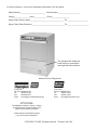
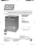
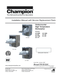
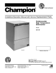
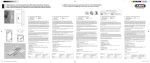
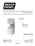
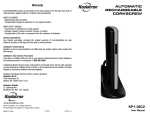
Installation Manual with Service Replacement Parts
Undercounter
High Temperature
Dishwasher
Model:
301HT M2
High temperature dishwasher
with built-in electric booster

Dishwasher Serial No.
Issue Date: 1.9.09
Manual P/N 114150 rev. B
www.moyerdiebel.com
P.O. Box 4183
Winston-Salem, NC 27115
336/661-1992 Fax: 336/661-1660
Toll-free: 800/858-4477
Beginning with S/N 61017 and above
2674 N. Service Road, Jordan Station
Ontario, Canada L0R 1S0
905/562-4195 Fax: 905/562-4618
Toll-free: 800/263-5798
Printed in the USA
For future reference, record your dishwasher information in the box below.
Model Number__________________________ Serial Number_______________________
Voltage________________Hertz_____________ Phase__________________
Moyer Diebel Service Agent __________________________________ Tel:______________________
Moyer Diebel Parts Distributor _________________________________ Tel:______________________
The data plate with model and
serial number is mounted the
lower right-side of the machine.
National Service Department
In Canada:
Toll-free:800/263-5798
Tel:
905/562-4195
Fax:
905/562-4618
email: [email protected] In the USA:
Toll-free: 800/858-4477
Tel:
336/661-1992
Fax: 336/661-1660
email: [email protected]
ATTENTION:
The dishwasher model no., serial no., voltage,
Hz and phase are needed to identify your
machine and to answer questions.
Please have this information on-hand
if you call for service assistance.
COPYRIGHT © 2009 All rights reserved
Printed in the USA
ATTENTION:
Complete the back of the POSTAGE PAID WARRANTY CARD below, then cut along
the dashed lines and mail immediately to make sure that your machine warranty is validated.
USE CANADIAN WARRANTY CARD IN CANADA AND USA WARRANTY CARD IN THE UNITED STATES.
NO POSTAGE
NECESSARY
IF MAILED
IN THE
UNITED STATES
BUSINESS REPLY MAIL
FIRST-CLASS MAIL PERMIT NO. 2101 WINSTON-SALEM, NC
POSTAGE WILL BE PAID BY ADDRESSEE
MOYER DIEBEL
PO BOX 4183
WINSTON-SALEM, NC 27119-0981
WARRANTY REGISTRATION CARD
Serial #
Model
Date of Installation:
Company Name:
Address:
Telephone #: (
)
---
(Street)
State or Province
Zip Code
Contact:
Installation Company:
Address:
Telephone #:
Contact:
This Card Must Be Returned to Validate Machine Warranty:
IMPORTANT
IMPORTANT
WARRANTY REGISTRATION CARD
Serial #
Model
Date of Installation:
Company Name:
Address:
Telephone #: (
)
---
(Street)
State or Province
Zip Code
Contact:
Installation Company:
Address:
Telephone #:
Contact:
This Card Must Be Returned to Validate Machine Warranty:
IMPORTANT
IMPORTANT
Revision History
Revision History
The Revision History can contain part number changes, new instructions, or information that
was not available at print time.
We reserve the right to make changes to this manual without notice and without incurring
any liability by making the changes.
Equipment owners may request a revised manual, at no charge, by calling
1 (800) 858-4477 in the USA or 1 (800) 263-5798 in Canada.
Revision Date
Revised
Pages
Serial Number
Effectivity
Revision
Description
4.15.06
All
61017
Released 1st edition
6.21.07
23
61017
Revised pump assembly P/N's
1.9.09
All
61017
Updated , added P/N's
i
Limited Warranty
Limited Warranty
Moyer Diebel Limited, P.O. Box 4183, Winston-Salem, North Carolina 27115, and P. O. Box 301, 2674 North Service
Road, Jordan Station, Ontario, Canada L0R 1S0 warrants machines, and parts, as set out below.
Warranty of Machines: Moyer Diebel Limited warrants all new machines of its manufacture bearing the name “Moyer Diebel”
and installed within the United States and Canada to be free from defects in material and workmanship for a period of
one (1) year after the date of installation or fifteen (15) months after the date of shipment by Moyer Diebel, whichever
occurs first. [See below for special provisions relating to Model Series DF and SW.] The warranty registration card must be
returned to Moyer Diebel within ten (10) days after installation. If warranty card is not returned to Moyer Diebel within such
period, the warranty will expire after one year from the date of shipment.
Moyer Diebel will not assume any responsibility for extra costs for installation in any area where there are jurisdictional
problems with local trades or unions.
If a defect in workmanship or material is found to exist within the warranty period, Moyer Diebel, at its election, will either
repair or replace the defective machine or accept return of the machine for full credit; provided, however, as to Model
Series DF and SW, Moyer Diebel’s obligation with respect to labor associated with any repairs shall end (a) 120 days after
shipment, or (b) 90 days after installation, whichever occurs first. In the event that Moyer Diebel elects to repair, the labor and
work to be performed in connection with the warranty shall be done during regular working hours by a Moyer Diebel authorized
service technician. Defective parts become the property of Moyer Diebel. Use of replacement parts not authorized by Moyer
Diebel will relieve Moyer Diebel of all further liability in connection with its warranty. In no event will Moyer Diebel’s warranty
obligation exceed Moyer Diebel’s charge for the machine. The following are not covered by Moyer Diebel’s warranty:
a. Lighting of gas pilots or burners.
b. Cleaning of gas lines.
c. Replacement of fuses or resetting of overload breakers.
d. Adjustment of thermostats.
e. Adjustment of clutches.
f. Opening or closing of utility supply valves or switching of electrical supply current.
g. Adjustments to chemical dispensing equipment.
h. Cleaning of valves, strainers, screens, nozzles, or spray pipes.
i. Performance of regular maintenance and cleaning as outlined in operator’s guide.
j. Damages resulting from water conditions, accidents, alterations, improper use, abuse, tampering, improper
installation, or failure to follow maintenance and operation procedures.
Examples of the defects not covered by warranty include, but are not limited to: (1) Damage to the exterior or interior finish
as a result of the above, (2) Use with utility service other than that designated on the rating plate, (3) Improper connection
to utility service, (4) Inadequate or excessive water pressure, (5) Corrosion from chemicals dispensed in excess of
recommended concentrations, (6) Failure of electrical components due to connection of chemical dispensing equipment
installed by others, (7) Leaks or damage resulting from such leaks caused by the installer, including those at machine table
connections or by connection of chemical dispensing equipment installed by others, (8) Failure to comply with local building
codes, (9) Damage caused by labor dispute.
Warranty of Parts: Moyer Diebel warrants all new machine parts produced or authorized by Moyer Diebel to be free
from defects in material and workmanship for a period of 90 days from date of invoice. If any defect in material and
workmanship is found to exist within the warranty period Moyer Diebel will replace the defective part without charge.
DISCLAIMER OF WARRANTIES AND LIMITATIONS OF LIABILITY. MOYER DIEBEL’S WARRANTY IS ONLY TO
THE EXTENT REFLECTED ABOVE. MOYER DIEBEL MAKES NO OTHER WARRANTIES, EXPRESS OR IMPLIED,
INCLUDING, BUT NOT LIMITED TO, ANY WARRANTY OF MERCHANTABILITY, OR FITNESS OF PURPOSE.
CHAMPION/MOYER DIEBEL SHALL NOT BE LIABLE FOR INCIDENTAL OR CONSEQUENTIAL DAMAGES.
THE REMEDIES SET OUT ABOVE ARE THE EXCLUSIVE REMEDIES FOR ANY DEFECTS FOUND TO EXIST
IN CHAMPION/MOYER DIEBEL DISHWASHING MACHINES AND MOYER DIEBEL PARTS, AND ALL OTHER
REMEDIES ARE EXCLUDED, INCLUDING ANY LIABILITY FOR INCIDENTALS OR CONSEQUENTIAL DAMAGES.
Moyer Diebel does not authorize any other person, including persons who deal in Moyer Diebel dishwashing machines,
to change this warranty or create any other obligation in connection with Moyer Diebel Dishwashing Machines.
ii
Table of Contents
Table of Contents
Revision History_ _____________________________________________________________ i
Limited Warranty______________________________________________________________ ii
Model Descriptions___________________________________________________________ iv
Installation _ _________________________________________________________ 1
Receiving__________________________________________________________________ 1
Electrical Connection_________________________________________________________ 3
Plumbing Connections________________________________________________________ 4
Chemical Dispensers_ _______________________________________________________ 5
Initial Start-up _ _____________________________________________________________ 6
Operation____________________________________________________________ 8
Cleaning _ __________________________________________________________ 19
De-liming ___________________________________________________________ 10
Maintenance_ ________________________________________________________11
Troubleshooting_ ____________________________________________________ 12
Service Replacement Parts_ ___________________________________________ 15
Electrical Schematic and Timing Chart___________________________________ 39
iii
Model Descriptions
Model Descriptions
Model 301HT M2:
High temperature hot water sanitization undercounter dishwasher with a
40°F/22°C rise built-in stainless steel electric booster heater.
Rinse-Sentry to ensure 180°F/82°C final rinse water temperature
Pressure regulating valve (PRV)
Built-in detergent and rinse-aid chemical dispensing pumps
13" door opening clearance
1 flat-bottom dish rack and 1 peg dish rack
1 year parts and labor warranty.
Options:
70°F/39°C rise built-in stainless steel electric booster heater
CST- Combination sink/table (Machine on right-side of table)
CST- Combination sink/table (Machine on left-side)
6" floor stand
17RS- 17" floor stand
Three phase operation
Additional flat-bottom and peg dish racks
iv
Installation
Receiving
1. Check the corrugated box that protected the dishwasher during shipment for punched holes
or impact marks.
2. Inspect the shipping pallet for splintered or broken boards.
3. Inspect the exterior of the dishwasher while still mounted on the pallet for signs of damage.
4. If no damage is found, proceed with lifting the dishwasher from its pallet.
Be careful to lift the dishwasher by the main frame if using a forklift.
5. Make sure the four legs are screwed firmly in place after landing the machine.
6. Check the packing list to ensure all accessories are with the dishwasher.
7. Complete the warranty card located at the front of this manual and mail at once
in order to validate your warranty.
8. Move the dishwasher close to its permanent location.
9. Remove the protective covering from the dishwasher and identify the utility connections.
Information cards and stickers must not be removed from the dishwasher until the
installation is complete.
1
Installation
Receiving
Care should be taken when lifting the machine to prevent damage.
The machine is normally shipped on a skid enclosed by straps. When transporting the machine,
use a lift truck or fork lift, positioning the box properly on the forks.
1. Immediately after unpacking your machine, inspect for any shipping damages. If damage is
found, save the packing material and contact the carrier immediately.
2. Remove the dishwasher from the skid. Adjust the feet if required, then move the machine to
its permanent location.
3. Level the machine (if required) by placing a level on the top if the machine and adjusting the
feet. Level the machine front-to-back and side-to-side.
4. Remove any foreign material from inside of the machine.
Note:
Installers must follow applicable sanitation, safety, plumbing, and electrical codes
and regulations; and work in accordance with best practices for dishwasher
installation.
2
Installation
Electrical Connections
Note:
Leave enough electrical cable behind the machine so that the dishwasher
can be pulled forward a minimum of two feet to be serviced.
Warning:
Electrical and grounding connections must comply with all local electrical codes or in the
absence of local codes then connections must comply with the National Electrical Code.
Warning: When working on the dishwasher, disconnect the main electric service and tag it to
indicate work is being done on that circuit.
1. The electrician should compare the electrical specifications on the machine electrical data
plate (located in the control panel) to the electrical power supply before connecting the
machine to the incoming service at a fused disconnect switch.
IMPORTANT: The 208-240V/60Hz/1PH electrical supply service for this machine must be a
2-wire plus ground service. For optional 208-240V/60Hz/3PH the electrical supply service
must be a 3-wire plus ground service.
2. On the 208V-240V models, a knockout is provided at the rear of the junction box for
electrical service connections. A fused disconnect switch or circuit breaker (supplied by
user) is required to protect each power supply circuit.
Refer to the MACHINE ELECTRICAL CONNECTION DATA PLATE for the
dishwasher power requirements.
3
Installation
Plumbing Connections
Water Connections
1. Connect the hot water supply to the fill hose provided with a 3/4" NPT fitting.
2. Install a manual shut-off valve in the water supply line to accommodate servicing the
machine. The shut-off valve should be the same size or larger than the supply line and
installed as close to the dishwasher as possible.
3. Install a 3/4" pressure reducing valve (PRV) (supplied with machine) in the water supply
line, and set at 20-22 PSI/138-151kPa. Install the PRV downstream from the service
shut-off valve and as close to the dishwasher as possible.
Drain Connections
1. Drain hose must be supported by bracket provided (shipped inside of machine).
2. The drain hose bracket must be mounted a minimum of 2 feet above the finished drain,
either on the rear of the machine or on the wall.
3. The maximum height of the drain from the floor must not exceed 3 feet.
4. Connect the 3/4"I.D. flexible drain hose to a 1-1/2" wye (Y) drain fitting. Use a 3/4" hose
Note:
Plumbing connections must comply with local health and plumbing codes.
Connect machine flexible
drain hose to a wye fitting.
4
Do not connect the machine
flexible drain hose to a
90° fitting.
Installation
Chemical Dispensers
ATTENTION:
Chemical dispensers must be electrically grounded in compliance with applicable electric codes.
adapter (supplied by others). Do not connect drain hose to a 90° drain fitting.
Detergent
The machine is equipped with an automatic detergent dispensing pump system.
1. Use a qualified detergent/chemical supplier for your detergent.
2. Your machine is supplied with a detergent dispensing pump that is internally wired and ready for
use. Use a commercial grade liquid detergent and insert the red pickup tube into the detergent
container. The pickup tube has a strainer on the end to prevent the crystallized chemical from
clogging the supply lines.
Always wash hands under running water if they come into contact with the detergent and comply
with the instructions pertaining to the specific type of detergent.
To prime the peristaltic pump:
1. Insert pick-up tube into the detergent container.
2. Close machine door and switch machine on.
3. Push and hold the prime switch.
Rinse Aid
1. Use a qualified/chemical supplier for your rinse aid needs.
2. Insert the transparent tube into the container containing the rinsing agent.
3. Push and hold the prime switch
Completing the Installation
1. Remove any foreign materials from inside the machine.
2. Install the scrap screens, wash and rinse arms, strainer basket and overflow tube.
3. After plumbing and electrical connections are completed, check machine for water leaks by
closing the door, then depressing the ON switch. This allows the tank to begin filling and to
reach temperature.
4. Open the door and check the water level. The water level should be 2 inches above the scrap screen.
5. Close the door fully.
Caution:
Connecting chemical dispensers at points other than those recommended by the factory
may damage the dishwasher electrical system. Damage caused by the installation of
chemical equipment will not be covered the WARRANTY.
5
Installation
Initial Start Up
1. The built-in stainless steel electric booster was shipped without water.
2. A manila card located above the power switch explains how to turn the
machine on for the first time. Initial Start-up:
1. Check the placement of the dishwasher:
Compare the machine location with the building plan.
2. Check that all options and/or accessories
are installed.
3. Remove protective white wrapping, tape,
and other packing materials and discard.
4. Remove any foreign materials from the interior of the machine.
6
Installation
Initial Start Up
The following is a summary of your model 301HT dishwasher operating cycle:
1. The door must be closed to begin the cycle.
2. Press the POWER button to fill the wash tank.
3. The booster heater comes on when the correct water level has been reached.
4. Press and hold the START button to start the cycle. NOTE : After pushing the start button
the first cycle of each day could take at least 15-20 minutes if the machine was not allowed
to warm up first.
5. The pump runs during the wash cycle for approximately 120 seconds. The wash cycle
duration is extended if the booster water temperature does not reach 180°F/82°C.
6. After a 5 second pause, the fill valve opens and the rinse cycle starts.
7. The machine rinses for 15 seconds. The cycle light turns off indicating that the cycle is
complete. DO NOT open the door until the cycle light turns off.
8. Open the door and remove the rack of clean ware.
7
Operation
Operation
Operation Procedures
1. Check that the spray arms, overflow tube and scrap screens are in place.
2. Close the door. Press the POWER switch. The tank will begin to fill with water.
This procedure is only needed when the tank is empty.
3. When the tank is full, check the wash tank temperature gauge. Minimum wash temperature
is 150°F/66°C.
4. Scrap and preflush all items to be washed, load items into rack. Wash only one layer of
silverware in a rack at a time.
Note: DO NOT OVERLOAD the rack.
5. Open the door and insert the rack of wares into the machine.
6. Close the door. Press the START switch and hold for 1 second, then release. This will start
the wash cycle. The light illuminates.
Note: The machine may be stopped at any time during the cycle by opening the door. Closing
the door resumes the cycle where it was stopped.
8
Cleaning
Cleaning
After Meal Periods or 8 Hours of Operation
1. Press power switch OFF
2. Remove the overflow tube and press and hold the DRAIN switch to drain the machine.
3. Wipe the interior to remove any debris.
4. Clean the screens after every meal period and more frequently during heavy usage.
Do not allow screens to become clogged with debris.
5. Inspect wash and rinse arms. Clean if necessary.
6. Replace overflow tube.
7. Close door.
8. Press the power button to refill machine.
Weekly
1. Check the dishwasher installation site and clean if necessary.
2. Inspect the area behind the dishwasher and clean as required.
3. Inspect the chemical supply containers for spills and clean.
9
Cleaning
De-liming
Danger:
Death or serious injury may result when de-liming solution is mixed with sodium hypochlorite (chlorine
bleach) sanitizing agent. Mixing may cause hazardous gases to form.
De-liming solution and other acids must never be mixed with chlorine, iodine, bromine, or fluorine. Caution:
Skin contact with de-liming solutions can cause severe irritation and possible chemical burns.
Always wear protective clothing when handling chemicals.
Attention:
Contact your chemical supplier for specific safety procedures and instructions for the use of
the de-liming solution supplied for the dishwasher.
De-liming solution or other chemicals are not supplied by the dishwasher manufacturer.
De-liming Procedure
1.
Remove the chemical pick-up tubes from their supply containers.
2.
Place the pick-up tubes in a container of warm water.
3.
Push each prime switch to flush remaining chemicals out of the chemical tubing.
3.
Close the door fully.
4.
Press the POWER switch to fill the machine.
5.
Open the door and add de-liming chemical into the wash tank compartment.
6.
Close the door fully, then press the START switch to begin a cycle.
7.
Run 3 complete cycles, then press the POWER switch to the OFF position.
8.
Open the door and remove the drain/overflow tube from the wash tank.
9.
Close the door.
10. Press and Hold the DRAIN switch to drain the machine.
11. Replace the drain/overflow tube, then close the door.
12. Re-insert the chemical pick-up tubes in the proper containers and prime the chemical
dispensing pumps.
13. De-liming is complete.
10
Maintenance
Daily Maintenance
Maintenance
Keep your dishwasher and the surrounding area clean.
Daily1.
Maintenance
2. Immediately
report loose,
broken
missing
to your
supervisor.
1. Check
the rinse temperature
during
theorfinal
rinse.parts
The final
rinse
must be
180°F/82°C
minimum.
3. Check drains for flow restrictions.
2. Clean
the scrap
screens after
4. Check
the dishwasher
forevery
leaks.meal period.
6. At5.
theOperate
end of the
any water
the tank in
should
be drained by pressing the POWER
theday,
dishwasher
asin
explained
this manual.
button to turn machine off and removing the drain/overflow tube. Press and hold the
DRAIN switch to activate the drain pump and completely drain the machine.
Monthly Maintenance
1. Inspect pump hoses, door linkage, springs, and exterior of dishwasher for wear.
Cleaning
2. InspectSchedule
the wash arm bearings and O-rings.
Check the condition of scrap screens, and dish racks for bent or broken pieces.
Meal 3.
Periods
4. Check the toggle switches and indicator lights for damage.
5. Check the wash pump motor for loud bearings and leaking pump seal.
Annual Maintenance
all your authorized service agent or local service representative and schedule
C
a complete inspection of your dishwasher by a trained professional.
11
Troubleshooting
Troubleshooting
In order to find the cause of a breakdown or abnormal operating condition in your dishwasher
please ensure that:
1. All power switches are ON.
2. Drain overflow tube is in place and seated.
3. Wash spray arm nozzles and rinse nozzles are clean.
4. Spray arms are in their proper positions.
5. Pump intake and wash tank screens are clean and properly positioned.
6. Detergent and rinse-aid dispensers are adequately filled.
7. Door is fully closed.
Refer to the Troubleshooting Guide below before contacting an authorized service agent for repair.
Condition
Cause
Solution
Cycle keeps running
and does not finish
Cold machine. . . . . . . . . . . . . . . . First cycle of the day could take
20 minutes if machine did not warm up.
Machine will not start Main switch disconnected . . . . . . Turn on switch.
Door not closed . . . . . . . . . . . . . . Make sure doors are fully closed.
Door safety switch faulty . . . . . . . Contact your service agency.
Start switch faulty. . . . . . . . . . . . . Contact your service agency.
Low or no water
Main water supply is turned off. . . Turn on house water supply.
Drain/overflow tube is not
in place and seated . . . . . . . . . . . Place and seat drain/overflow tube.
Machine doors not fully closed. . . Close doors securely.
Faulty fill valve. . . . . . . . . . . . . . . Contact your service agency.
Continuous filling
Fill valve will not close. . . . . . . . . Contact your service agency.
Drain/overflow tube not in place. . Install drain/overflow tube in tank.
Air trap lost pressure . . . . . . . . . . Drain machine, reinsert drain/overflow.
.and refill machine.
Motor not running
Defective motor . . . . . . . . . . . . . . Contact your service agency.
Wash water temp
Incoming water temp low. . . . . . . Raise temperature to 140°F/40°C
to low when in use for 40°F/22°C rise booster heater.
Raise temperature to110°F/39°C
for 70°F/39°C rise booster heater.
Defective thermometer. . . . . . . . . Check or replace.
Defective thermostat . . . . . . . . . . Check for proper setting or replace.
Defective heater element. . . . . . . Check or replace.
12
Troubleshooting
Troubleshooting
Condition
Cause
Solution
Insufficient pumped spray pressure
Clogged pump intake screen. . . . . .
Clogged spray pipe . . . . . . . . . . . . .
Scrap screen full. . . . . . . . . . . . . . . .
Low water level in tank. . . . . . . . . . .
Defective pump seal. . . . . . . . . . . . .
Clean
Clean
Must be kept clean and in place
Check drain and overflow tube
Contact service agent
Insufficient final rinse or Clogged rinse nozzle and/or arm. . . Clean with paper clip/delime
no final rinse
Clogged strainer. . . . . . . . . . . . . . . . Clean or replace
Low final rinse Low incoming water. . . . . . . . . . . Check the booster be sure the
temperature
thermostat is set to maintain 180°F/82°C temperature.
Check fill valve operation.
Defective thermometer. . . . . . . . . . . Check for proper setting or replace
Poor washing results
Detergent dispenser not
operating properly . . . . . . . . . . . . . . Contact detergent supplier
Insufficient detergents. . . . . . . . . . . Contact detergent supplier
Food Soil concentration too
high in wash tank. . . . . . . . . . . . . . . Drain tank, clean and refill every
2 hours of operation or after each
meal period.
Wash water temperature too low. . . See condition “Wash Tank
Water Temperature” above
Wash arm clogged. . . . . . . . . . . . . . Clean
Wash arm not rotating. . . . . . . . . . . Clean arm. Check bearing,
replace if necessary.
Improperly scrapped dishes. . . . . . . Check scrapping procedures
Ware improperly placed in rack. . . . Use proper racks. Do not overload racks
Improperly cleaned equipment . . . . Unclog wash sprays and rinse nozzles
to maintain proper pressure and flow
conditions. Overflows must be open.
Keep wash water as clean as possible.
Heating element has
soil/lime buildup. . . . . . . . . . . . . . Clean and/or de-lime.
Detergent pick up tube
in incorrect container. . . . . . . . . . Place RED pick up tube in
detergent container
13
Blank Page
This Page
Intentionally
Left Blank
14
Service Replacement Parts
Service Replacement Parts
Illustrations
Page
Hood and Tank Assembly . . . . . . . . . . . . . . . . . . . . . . . . . . . . . . . . . . . . . . . . . . . . . . . . . . . 16
Door Assembly . . . . . . . . . . . . . . . . . . . . . . . . . . . . . . . . . . . . . . . . . . . . . . . . . . . . . . . . . . . 18
Wash Tank Heater and Chemical Dispensers . . . . . . . . . . . . . . . . . . . . . . . . . . . . . . . . . . . . 20
Fill Piping Assembly . . . . . . . . . . . . . . . . . . . . . . . . . . . . . . . . . . . . . . . . . . . . . . . . . . . . . . . 22
Drain Assembly . . . . . . . . . . . . . . . . . . . . . . . . . . . . . . . . . . . . . . . . . . . . . . . . . . . . . . . . . . . 24
Wash and Rinse Piping Assembly . . . . . . . . . . . . . . . . . . . . . . . . . . . . . . . . . . . . . . . . . . . . 26
Wash and Rinse Arm Assemblies . . . . . . . . . . . . . . . . . . . . . . . . . . . . . . . . . . . . . . . . . . . . . 28
Wash Pump/Motor Assembly . . . . . . . . . . . . . . . . . . . . . . . . . . . . . . . . . . . . . . . . . . . . . . . . 30
Booster Heater Assembly . . . . . . . . . . . . . . . . . . . . . . . . . . . . . . . . . . . . . . . . . . . . . . . . . . . 32
Control Panel Assembly . . . . . . . . . . . . . . . . . . . . . . . . . . . . . . . . . . . . . . . . . . . . . . . . . . . . 34
Control Cabinet Assembly . . . . . . . . . . . . . . . . . . . . . . . . . . . . . . . . . . . . . . . . . . . . . . . . . . . 36
15
Hood and Tank Assembly
11
1
10
7
11
2
12
12
13
A
7
3
12
7
3
9
11
8
12
4
11
5
7
16
6
Hood and Tank Assembly
Item No.
Part No.
Description
Qty.
Unit
1
H36145
Panel, Control Cabinet 1
ea
2
H36147
Panel, Side RH 1
ea
3
H35551
Tracks, Rack 2
ea
4
H36151
Panel, Front 1
ea
5
H33576
Bottom Panel 1
ea
6
H25209
Foot, Adjustable 4
ea
7
H25697
Self-Tapping Screw 9 x 13 12
ea
8
H36146
Panel, Side LH 1
ea
9
H25693
Self-Tapping Screw Bevel 2 x 13 4
ea
10
H36148
Panel, Back 1
ea
11
H36728
Screw TS M5 x 20 6
ea
12
H450821
Spring Clip Fastener 5MA 8
ea
13
H36353
Gasket, Top 1
ea
A
HARDWARE FOR TRACKS (Quantities per track)
H25744
Washer 2
ea
H25774
Nut. 5MM 2
ea
17
Door Assembly
1
2
1
3
2
4
3
4
5
18
5
6
17
7
6
7
8
26
8
25
9
24
20
27
19
9
23
22
13
21
12
11
27
10
16
14
15
14
18
Door Assembly
Item No.
1
2
3
4
5
6
7
8
9
10
11
12
13
14
15
16
17
18
19
20
21
22
——
23
24
25
——
26
27
Part No.
H25791
106486
107623
H30194
H37104
H160909
H160837
H33387
H34144
H25746
H25792
H33336
H25693
H33277
H32969
H37162
H260223
H35171
H30473
H37121
H34360
H37124
H37123
H37170
H37171
H37120
H37119
H37122
H36174
Description
Nut Plain
Washer
Nut Door Support
Nut
Door Rod Plate Support
Door Rod Plate
Gasket
Screw
Door Rod
Washer
Nut
Door Catch
Self-Tapping Screw Self-Tapping Screw Door Magnet Door Weldment (Does not include hardware) Screw Washer
O-ring
Hub
O-ring
Left Counter Balance Lever
Right Counter Balance Lever (Not shown) Spring Hook
Door Spring
Left Counter Balance Rod
Right Counter Balance Rod
Guide
Door Rod Bushing
Qty.
Unit
2
2
2
4
2
2
2
4
2
2
2
1
2
2
1
1
2
2
2
2
2
1
1
2
2
1
1
2
2
ea
ea
ea
ea
ea
ea
ea
ea
ea
ea
ea
ea
ea
ea
ea
ea
ea
ea
ea
ea
ea
ea
ea
ea
ea
ea
ea
ea
ea
19
Wash Tank Heater and Chemical Dispensers
1
2
3
8
13
Detergent
pump
13
4
9
10
11
4
12
7
Rinse-aid
pump
22
4
4
14
15
17
16
18
19
20
21
20
5
6
Wash Tank Heater and Chemical Dispensers
Item No.
Part No.
Description
Qty.
Unit
1
H35162
Wash Tank Heater 2000W 230V
1
ea
2
113604
Wash Tank High Limit Thermostat
1
ea
3
H36351
Support Plate, for Wash Tank High Limit
1
ea
4
H34982
Screw M5 X 12 Half Round Head
14
ea
5
H441402
Pressure Gauge
1
ea
6
H460344
Plate, Adhesive
1
ea
7
H36154
Bracket, Pressure Gauge
1
ea
8
111100
Elbow, 1/4" OD x 1/8" MPT 90° Plastic
1
ea
9
0502563
Clamp, Hose
1
ea
10
107928
1/4" Natural Tubing
A/R
ft.
11
H34358
Peristaltic Pump, Detergent 1
ea
12
H35137
Squeeze Tube, Detergent (comes with black fittings) 1
ea
13
H36271
Bracket, Peristaltic Pump
2
ea
14
H37110
Peristaltic Pump, Rinse-aid
1
ea
15
H37296
Squeeze Tube, Rinse (comes with black fittings)
1
ea
16
0512475
Supply Tubing, Detergent (comes in 13 ft. roll)
1
ea
17
H00166
Supply Tubing, Rinse-aid A/R
ft.
18
H180726
Strainer, Supply Tubing
2
ea
19
H33745
Hi Limit Thermostat
1
ea
20
H36397
Thermostat, Adjustable, Rinse, 86-203°F/30-95°C
1
ea
21
H25417
Thermostat, Adjustable, Wash, 86-194°F/30-90°C 1
ea
22
H25092
Knob, Thermostat
2
ea
21
Fill Piping Assembly
22
Fill Piping Assembly
Item No.
1
2
3
4
5
–
6
7
8
9
10
11
12
13
14
15
16
17
18
19
20
21
22
23
24
25
26
27
28
Part No.
H36156
0502651
0503679
H00182
100500
900836
0502651
H36173
H36289
H36607
H36290
H160121
H25239
H34733
H25011
H25778
H18472
H25263
H25010
H26629
H36172
H36349
H280607
H160117
H36032
H33344
H34996
H200415
107550
Description
Qty.
Unit
Vacuum Breaker Mounting Box 1
ea
Hose Barb 4
ea
Clamp, HoseA/R
Hose, BlueA/R
A 23-5/8" [600mm]
B 15-3/4" [400mm]
C 8-1/16" [205mm]
D 36-1/4" [920mm]
E 8-3/16" [201mm]
F 8-1/16" [205mm]
Vacuum Breaker 1/2" NPT
1 ea
Repair* Kit 1/2" Vacuum Breaker
A/R
Hose Barb 3
ea
Cross Tee 1
ea
Right for Brass Insert 1
ea
Brass Insert 1
ea
Raccord, Brass Insert 1
ea
Hose BlackA/R
Gasket 1
ea
Clamp 1
ea
Cover for Air Trap 1
ea
Nut, Injector 1
ea
Detergent Injector 1
ea
Flat Gasket 1
ea
Air Trap 1
ea
Solenoid Valve 3/4"
1 ea
TEE, 1/2" x 1/2" x 1/8"
1 ea
Brass Reduction 1
ea
ea
Valve 1
Poly TubeA/R
Drain Hose 1
ea
Cable Clip 1
ea
Inlet Tube 1
ea
O-ring, Gasket 1
ea
Valve Press Reducing 3/4"
1 ea
23
Drain Assembly
To Drain
17
1
2
3
4
6
8
9
5
7
18
13
17
14
10
11
20
14
19
12
16
14
15
24
Drain Assembly
Item No.
Part No.
Description
Qty.
Unit
1
H32796
Cover, Round Filter 1
ea
2
H32795
Bottom, Round Filter 1
ea
3
H36160
Overflow Tube, Drain Pump
1
ea
4
H35895
Scrap Screen 1
ea
5
H25684
Self-Tapping Screw 9mm x 9mm 6
ea
6
H35896
Sump Cover 1
ea
7
H32719
Rubber Sump 1
ea
8
H25006
Nut, Drain Suction 1
ea
9
H34790
Drain Elbow Series 1
ea
10
H26637
Flat Gasket Drain 1
ea
11
H31423
Flat Gasket Suction 1
ea
12
H32715
90° Suction Elbow 1
ea
13
H30421
Drain Fitting Long 1
ea
14
0502563
Clamp, Hose 4
ea
15
H32894
Suction Hose 1
ea
16
H32801
Suction Sleeve, Drain Pump 1
ea
17
H36032
Drain Hose 1
ea
18
H35544
Drain Pump 1
ea
19
H35359
Bracket, Drain Pump 1
ea
20
H28226
O-ring, Gasket 1
ea
25
Wash and Rinse Piping Assembly
2
1
3
4
5
6
7
BOTTOM OF TANK
8
5
4
A
9
10
10
11
12
13
A
26
Wash and Rinse Piping Assembly
Item No.
Part No.
Description
Qty.
Unit
1
0502563
Jubilee Clip 1
ea
2
110215
Screw SS 1
ea
—
107873
Gasket 1
ea
3
H35509
Hub, Upper Arm
1
ea
4
0503674
Clamp, Hose 2
ea
5
H00182
Hose, Blue RinseA/R
ft.
6
H35550
Wash Delivery Sleeve 1
ea
7
H36279
Lower Wash Support 1
ea
8
109466
O-ring 1
ea
9
H36280
Lower Holder Revolving Arm 1
ea
10
0502571
Clamp, Hose 2
ea
11
0512322
Clamp, Hose 1
ea
12
H32894
Suction Hose 1
ea
13
H29043
Capacitor 16 UF/450V
A
1
ea
HARDWARE FOR MOUNTING PUMP
H25751
Split Spacer 8
ea
H25745
Lock Washer 8
ea
H25730
Hex Screw M8 x 25 4
ea
27
Wash and Rinse Arm Assemblies
1
2
3
4
1
5
6
6
8
9
7
8
6
7
6
5
1
4
9
2
3
28
1
Wash and Rinse Arm Assemblies
Item No.
Part No.
Description
Qty.
Unit
*1
-----------
Bearing, Wash Arm 4
ea
2
112549
Hub, Wash Arm 2
ea
3
H420548 Assy, Wash Arm Complete 2
ea
4
112550
Locknut, Wash Arm 2
ea
5
H34998
Nut Spacer 2
ea
6
H190663
Bushing, Rinse Arm 4
ea
7
H36257
Rinse Nozzle 6
ea
8
H36275
Pin, Revolving Rinse Arm 2
ea
9
H36211
Rinse Arm 301 2
ea
* Use Kit No. 0712749 whenever a wash arm bearing needs to be replaced.
The bearings are pressed into the wash arm hub at the factory to ensure that
they are seated properly.
The Kit includes:
Part No. Description
Qty. 112551 Bearing Wash Arm
2
112549
Hub, Wash Arm
1
112550
Locknut, Wash Arm
1
29
Wash Pump/Motor Assembly
30
Wash Pump/Motor Assembly
Item No.
Part No.
Description
Qty.
Unit
1
H36354
Pump Body 1
ea
2
110285
Gasket Pump Body 1
ea
3
H26204
Impeller 1
ea
4
H36355
Shaft Seal 1
ea
5
H36356
Flange Wash Pump 1
ea
–
H36129
Wash Pump/Motor Assy. (Includes Items 1-5) 1
ea
31
Booster Heater Assembly
6
2
5
7
5
6
8
4
9
10
32
3
Booster Heater Assembly
Item No.
Part No.
Description
Qty.
Unit
1
H36250
Heater 4000W 230/380V, 40°F/22°C Rise 1
ea
---
H33400
Heater 6000W 230/380V 70°F/39°C Rise 1
ea
2
H161123
Element Cap 1
ea
3
109985
O-ring 1
ea
4
H35816
Rinse-aid Inlet Fitting 1
ea
5
0503679
Clamp, Hose 2
ea
6
H00182
Hose, BlueA/R
ft.
7
H36150
Booster Tank 1
ea
8
H34192
Gasket 1
ea
9
H25274
Gasket 1
ea
10
H26863
Drain Plug 1
ea
33
Control Panel Assembly
11
10
5
3
4
1
2
34
7
6
8
9
Control Panel Assembly
Item No.
Part No.
Description
Qty.
Unit
1 H450916
Thermometer (Does not include Item 3) (Be sure to order Item 3)
2
ea
2
H460344
Plate, Adhesive
2
ea
3
H36607
Packing Nut
2
ea
4
H37169
Prime Switch
2
ea
5
H37179
Drain Switch (Push button only does not include Item 6)
1
ea
6
H32928
Contact Block, Double Pole, Drain Switch
1
ea
7
H37178
Start Switch (Push button only does not include Item 8)
1
ea
8
H32928
Contact Block, Double Pole, Start Switch
1
ea
9
0512234
Cycle Light
1
ea
10
H37168
Covered On/Off Switch
1
ea
11
H37174
Decal
1
ea
(Beginning with S/N 66190 and above)
35
Control Cabinet Assembly
36
Control Cabinet Assembly
Item No.
Part No.
Description
Qty.
Unit
1
H160121
Hose, Black Rubber 1
ea
2
H31643
Clamp, Hose 1
ea
3
H31171
Pressure Switch 1
ea
4
H34312
Relay 16A 230V 1
ea
5
H36142
Timer 230V 60Hz 1
ea
6
H31982
Booster Heater Contactor 220V 1
ea
7
H36357
Junction Box 1
ea
8
H260248
Screw M5 x12 2
ea
—
——
Terminal Block Earth (Ground) 1
ea
9
H34046
Drawer Stop Rope (Not Shown) 1
ea
10
H33188
Magnetic Switch (Not Shown) 1
ea
37
Blank Page
This page
intentionally
left blank
38
Electrical Schematics and Timing Chart
Electrical Schematic and
Timing Chart
39
Electrical Schematic
40
Timing Chart
41
42