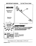
1
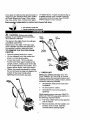
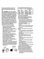
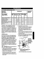
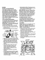
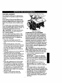
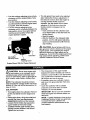
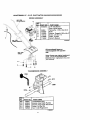
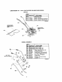
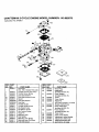
49.2cc 2-cycle
2.0HP 10 Inch Tines
CULTIVATOR
MODEL NO.
536.292510
536.292520
Caution:
Read and follow all Safety
Rules and Operating
nstructions before first use
_f this product.
SEARS, ROEBUCK AND CO., Hoffman Estates, IL 60179 U.S.A.
712452 12/09198
Table of Contents
Warranty
Safety Rules
Contents of Shipping Carton
Assembly
Operation
Maintenance
LIMITED
ONE-YEAR
2
2
2-4
4
4
5-8
9-10
WARRANTY
Service and Adjustments
Storage
Troubleshooting
Cultivator Repair Parts
Engine Repair Parts
Spanish (Espa5ol)
Parts Ordering/Service
ON CRAFTSMAN
11-12
12-13
13
14-16
17-20
21-34
Back Cover
CULTIVATOR
For one year from the date of purchase, when this Craftsman cultivator is maintained,
lubricated, and tuned up according to the operating and maintenance instructions in
the owner's manual, Craftsman will repair, free of charge, any defect in material or
workmanship.
This warranty excludes tine(s), spark plug, and air cleaner which are expendable
and become worn during normal use.
parts
If this Craftsman cultivator is used for commercial or rental purposes, this warranty applies for only 30 days from the date of purchase. This warranty applies only while this
product is in use in the United States. WARRANTY SERVICE IS AVAILABLE BY RETURNING THE CULTIVATOR TO THE NEAREST CRAFTSMAN SERVICE CENTER
IN THE UNITED STATES.
This warranty gives you specific legal rights, and you may also have other rights which
vary from state to state.
SEARS, ROEBUCK
AND CO., D817WA,
Hoffman Estates, IL 60179
,_
Look for this symbol to point out important safety precautions.
ATFENTIONI!!
Become alertlll Your safety is involved,
Z_
CAUTION:
Always disconnect spark
plug wire and place wire where it cannot
contact spark plug to prevent accidental
starting when setting-up, transporting,
adjusting or making repairs.
IMPORTANT: Safety standards require
operator presence controls to minimize the
risk of injury. Your cultivator is equipped
with such controls. Do not attempt to defeat
the function of the operator presence
control under any circumstances.
BEFORE USE
It means --
"o Keep the area of operation clear of all
persons, particularly small children and
pets.
• Thoroughly inspect the area where the
cultivator is to be used and remove all
foreign objects.
FUEL SAFETY
.
• Handle fuel with care; it is highly flammable.
• Use an approved container.
• Read the owner's manual carefully. Be
thoroughly familiar with the controls and
the proper use of the cultivator. Know
• Check fuel supply before each use,
allowing space for expansion as the heat
of the engine and/or sun can cause fuel to
expand.
• Fill fuel tank outdoors with extreme care.
how to stop the cultivator and disengage
the controls quickly.
• Do not operate the cultivator without
Never fill fuel tank indoors. Replace fuel
tank cap securely and wipe up spilled
fuel.
wearing adequate outer garments. Wear
footwear that will improve footing on
slippery surfaces.
• Never remove the fuel tank cap or add
fuel to a running or hot engine.
•
Never store fuel or cultivator with fuel in
the tank inside a building where fumes
may reach an open flame.
OPERATING
SAFETY
• Never allow children or young teenagers
to operate the cultivator. Keep them
away while it is operating. Never allow
adults to operate the cultivator without
proper instruction.
• Do not operate this machine if you are
taking drugs or other medication which
can cause drowsiness or affect your
ability to operate this machine.
,, Do not use this machine if you are
mentally or physically unable to operate
this machine safely.
• Always wear safety glasses or eye
shields during operation or while performing an adjustment or repair to protect
your eyes from foreign objects that may
be thrown from the cultivator.
• Do not put hands or feet near or under
rotating parts.
• Exercise extreme caution when operating
on or crossing gravel drives, walks, or
roads. Stay alert for hidden hazards or
traffic.
• Exercise caution to avoid slipping or
falling.
• Never operate the cultivator without
proper guards, plates, or other safety
protective devices in place.
• Never operate the cultivator at high
transport speeds on slippery surfaces.
Look behind and use care when backing.
• Never allow bystanders near the cultivator.
• Keep children and pets away while
operating.
• Never operate the cultivator without good
visibility or light.
• Do not run the engine indoors. The
exhaust fumes are dangerous, containing
CARBON MONOXIDE, an ODORLESS
and DEADLY GAS.
• Take all possible precautions when
leaving the cultivator unattended. Stop
the engine.
• Do not overload the cultivator capacity by
attempting to till too deep at too fast a
rate.
SAFE STORAGE
• Always refer to the owner's manual
instructions for important details if the
cultivator is to be stored for an extended
period.
• Never store the cultivator with fuel in the
fuel tank inside a building where ignition
sources are present such as water and
space heaters, clothes dryers, and the
like. Allow the engine to cool before
storing in any enclosure.
• Keep the cultivator in safe working
condition. Check all fasteners at frequent
intervals for proper tightness.
REPAIPJADJUSTMENTS
SAFETY
• After striking a foreign object, stop the
engine. Remove the wire from the spark
plug, and keep the wire away from the
plug to prevent accidental starting.
Thoroughly inspect the cultivator for any
damage, and repair the damage before
restarting and operating it.
• If cultivator should start to vibrate
abnormally, stop engine and check
immediately for the cause. Vibration is
generally a warning of trouble.
• Stop the engine whenever you leave the
operating position. Also, disconnect the
spark plug wire before unclogging the
tines and when making any repairs,
adjustments, or inspections.
• When cleaning, repairing, or inspecting,
shut off the engine and make certain all
moving parts have stopped.
• Never attempt to make any adjustments
while the engine is running except when
specifically recommended by the manufacturer.
Z_
WARNING:
The engine exhaust
from this product contains chemicals
known to the State of California to cause
cancer, birth defects or other reproductive
harm.
_
WARNING:
This unit is equipped
with an internal combustion engine and
should not be used on or near any unimproved forest-covered, brush-covered or
grass-covered land unless the engine's exhaust system is equipped with a spark arrester meeting applicable local or state laws
(if any). If a spark arrester is used, it should
be maintained in effective working order by
the operator.
In the state of California the spark arrester is
required by law (Section 4442 of the California Public Resources Code). Other states
may have similar laws. Federal laws apply
Parts
packed
separately
in carton
on federal lands. A spark arrester/muffler is
available through your nearest Craftsman
Authorized Service Center (See REPAIR
PARTS section in this manual).
(not shown
full
size)
1 - 5.3 Ounce 2-cycle Oil
1 - Owner's Manual (not shown)
A
CAUTION:
Always wear safety
glasses or eye shields while assembling
the Craftsman cultivator.
ht
The figure to the right shows the cultivator
completely assembled.
References to the right or left hand side
of the cultivator are from the viewpoint of
the operator's position behind the unit.
TO REMOVE
CULTIVATOR
FROM
CARTON
Control
• Remove packing insert from carton.
• Lift the cultivator out of the carton and
place on a hard level surface.
• Loosen tee knobs. Tilt the cultivator
forward and rotate upper handle to the
upright position, making sure the throttle
is not caught between the handles. Then
tighten the tee knobs. See figure below.
• Tighten the handle hardware by holding
the curved head carriage bolt against the
outside of the lower handle while
tightening the tee knobs securely.
Left
Handle
Depth
Stake
Tine
,/ CHECKLIST
Before you operate and enjoy your new
CRAFTSMAN CULTIVATOR, to ensure
that you receive the best performance and
satisfaction from this quality product, please
review the following checklist:
J
All assembly instructions have been
completed.
,I
No loose parts in carton.
,/
All fasteners have been properly
tightened.
While learning how to use your CRAFTSMAN CULTIVATOR, pay extra attention to
the following important items:
,/,/
,/,/
Fuel tank is filled with correct gasoline
and oil mixture.
Become familiar with the location and
function of all controls. Operate
controls before starting engine.
KNOW YOUR CULTIVATOR
READ THIS OWNER'S MANUAL AND SAFETY RULES BEFORE OPERATING YOUR
CRAFTSMAN CULTIVATOR. Compare the illustrations with your cultivator to familiarize
yourself with the location of various controls and adjustments. Save this manual for future
reference.
@
Half Choke
Off
A
Choke
Stop
I\1
FoI, Choke
Right Side
Upper Handle
Left Side
Upper Handle
Left Side
Lower Handle
Control
Choke
FuelTank
Right Side
Lower Handle
Depth Stake/
Transport Wheels,
Assembly
Shield
Depth Rc_/
Transport
Assembly
Throttle Control - Controls the engine
speed and the tine rotation. This cultivator is
equipped with a centrifugal clutch that engages the tine ddve system when the engine speed is increased.
Choke Control Lever - Used to assist in
starting a cold engine.
On-Off Switch - ON - Allows the unit to be
started. OFF - Stops the engine and keeps
the unit from being started.
Recoil Starter Handle - The engine on this
cultivator is equil_ped with an easy pull recoil starter.
Depth Stake or Depth Rod/Transport
Wheels Assembly - Used (with wheels up)
when cultivating to adjust the depth of the
cut. It also acts as a brake to help the operator control the direction and speed of the
unit.
The depth stake or depth rod/transport
wheel assembly (with wheels down) can be
used for transporting the unit.
HOW TO USE YOUR CULTIVATOR
/_
WARNING:
The operation of this cul-
tivator can result in foreign objects being
thrown into the eyes, which can cause severe eye damage. Always wear safety
glasses or eye shields while operating the
unit.
We recommend standard safety glasses or
Wide Vision Safety Mask for over your
glasses.
TO STOP CULTIVATOR
• Release the throttle control to stop the
tines.
• Move the on-off switch on the engine to
the OFF position.
OPERATE
CULTIVATOR
Set the depth stake or depth rod/transport
wheels assembly to the desired tilling
position as follows:
• Remove the hairpin from the clevis pin
securing the depth stake or depth red.
Remove the clevis pin and adjust the
depth stake or depth red upward to dig
shallower or downward to dig deeper.
Reinstall the clevis pin and hairpin.
Depth Stake/
Transport Wheels
Assembly
\
Clevis Pin.X_
Dep_ Stake_
urac_t
_
_
__
__
Hairptn._.
_
"_
'_
L--_
'_'_
I_
_J
Wheel Support Rod
Assembly
Dep_ Round
• Start the engine, tilt the unit back on the
depth stake or depth red until the tines
are off the ground and squeeze the
throttle control all the way up against the
hand grip. The engine is govemor
controlled and should be run at full throttle.
• Grasp the handles firmly and slowly tilt the
unit forward to begin the tilling action.
• As the tines begin to make contact with the
ground, hold back on the handles so that
the tines will dig and not ride forward over
the ground. Hold back until the tines dig
into the soil.
• If the tilled depth is too deep or too
shallow, turn off the engine and reset the
depth stake or depth rod.
• If depth stake or depth rod is not controlling forward action, lower the depth stake
or depth red. If the unit is not going
forward, raise the depth stake or depth
rod.
/K
CAUTION:
Keep away from the ro-
tating tines. Rotating tines can cause injury.
BEFORE STARTING
ENGINE
FILL GAS
The two cycle engine used on this cultivator
requires a mixture of gasoline and oil for lubrication of the bearings and other moving
parts. The correct fuel mixture ratio is 24:1
(see Fuel Mixture Chart). Gasoline and oil
must be premixed in a clean gasoline container. Always use fresh, clean unleaded
gasoline.
/_.
CAUTION:
Gasoline is flammable
and caution must be used when handling
or storing it. Do not fill fuel tank while cultivator is running hot or when it is in an enclosed area. Keep fuel away from open
flame and electrical spark. DO NOT
SMOKE while mixing fuel or filling the fuel
tank. Never fill fuel tank completely, but fill
it to within 1/4 - 1/2 inch from the top to
provide space for expansion of fuel. Always fill fuel tank outdoors and use a funnel or spout to prevent spilling; Make sure
to wipe up 0ny spilled fuel before starting
the engine.
Store gasoline in a clean, approved container, and keep the cap in place on the
container. Keep gasoline in a cool, wellventilated place, never indoors. To assure
volatility, never buy more than a 30 day
supply of gasoline. Gasoline is intended to
be used as a fuel for internal combustion
engines; therefore, do not use gasoline for
any other purpose. Since many children
like the smell of gasoline, keep it out of
their reach because the fumes are dangerous to inhale, as well as being explosive.
Z_
WARNING:
Experience indicates
that alcohol blended fuels (called gasohol or
using ethanol or methanol) can attract moisture which leads to separation and formation of acids during storage. Acidic gas can
damage the fuel system of an engine while
in storage. To avoid engine problems, the
fuel system should be emptied before storage for 30 days or longer. Drain the gas
tank, start the engine and let it run until the
fuel lines and carburetor are empty. Use
fresh fuel next season. See Storage Instructions for additional information. Never use
engine or carburetor cleaner products in the
fuel tank or permanent damage may occur.
GASOLINE AND OIL MIXTURE
Mix gasoline and oil 24:1 as follows:
• Pour 1 U.S. quart of fresh, clean,
unleaded automotive gasoline into a
gallon gasoline container.
• Add 5.3 oz.(found in carton) of clean,
high quality SAE 30 or SAE 40 two-cycle
oil into the gasoline container.
IMPORTANT:
DO NOT use Outboard
Motor Oil or Multi-Viscosity Oils, such
as 10W-30 or 10W-40.
• Reinstall the cap on the gasoline container and shake container vigorously so
the oil mixes with the gasoline.
• Add an additional 3 U.S. quarts of
gasoline to the gallon container and
shake the container again.
• This completes the special gasoline
mixing procedure. It can now be poured
into the cultivator fuel tank.
IMPORTANT:
DO NOT fill fuel tank with
gasoline that does not have oil mixed in
it. Do not use gasoline additives because
the engine may be damaged. Shake the
gasoline container before each filling of
the fuel tank.
Add More Gas
(3 U.S. Quarts)
or 5.3 oz.
1 U.S.
Gallon
Container
'_.
Shake Can
FUEL MIXTURE
CHART (Mixture 24:1)
u.S.
GAS
S.I. (METRIC)
OIL
GAS
OIL
1 Gal.
5.3 oz.
4 Liters
.167 L
2 Gal.
11 oz.
8 Liters
.333 L
5 Gal.
27 oz.
20 Liters
.833 L
TO START
THE
ENGINE
Before starting the engine, be sure you
have read and understood all the instructions on the preceding pages.
• Fill the fuel tank to 1/2 inch below the
bottom of the fill neck with fresh fuel mix
and reinstall the fuel tank cap securely.
Never use fuel that may be stale from
long periods of storage.
• Move the on-off switch to the ON
position.
• Move the choke control (see figure, page
5) to the FULL CHOKE position (all the
way down).
NOTE: A warm engine should not require
choking.
• Tilt the cultivator back on the depth stake
or transport wheels to raise the tines off
the ground.
• Grasp the upper handle firmly to stabilize
the cultivator.
• Move shut-off toggle switch to ON.
• Move choke lever to FULL CHOKE
position.
• Grasp starter handle and pull slowly until
you feel drag.
• Return starter handle slowly to original
position.
• Pull handle with rapid, full arm strokes
until engine starts.
• When engine starts, move choke lever to
HALF CHOKE position.
• When engine runs smoothly, move choke
lever to NO CHOKE position.
NOTE: If the tines do not stop when the
throttle control is released, adjust the
carburetor idle speed as instructed in
Carburetor Adjustment paragraph in the
Service/Adjustments
section on page 11.
• To stop the engine, release the throttle
control and move the on-off switch to the
OFF position.
• If the engine becomes flooded, see the
Spark Plug Maintenance paragraph in the
Maintenance section of this manual.
Then pull the starter rope with the choke
lever in the NO CHOKE position.
Z_
CAUTION:
The muffler and surrounding areas become hot after running
the engine. Avoid these areas.
CULTIVATING
HINTS
• Tilling is digging in, turning over and
breaking up packed soil before planting.
Loose unpacked soil helps root growth.
Best tilling depth is 4 to 6 inches. A tiller
will also clear the soil of unwanted
• When using the cultivator to remove
weeds, it is best to cultivate no deeper
than 1-1/2 inches. Cultivating deeper will
only pull to the surface ungerminated
weed seeds. You may want to raise the
depth bar to lessen the braking action.
• When cultivating around plants or close
areas, you may want to remove the
outside tines (see Tine Replacement
paragraph in the Service/Adjustments
section of this manual).
/_
CAUTION:
• Read the Owner's manual.
• Know location and functions of all
controls.
vegetation. The decomposition of this
vegetation matter enriches the soil.
Depending on the climate (rainfall and
wind), it may be advisable to till the soil at
the end of the growing season to further
condition the soil.
• Keep all safety devices and shields in
place.
• Never allow children or uninstructed
adults to operate cultivator.
• Shut off engine before unclogging tines or
making repairs.
• Keep bystanders away from machine.
• Keep away from rotating parts and tines.
They can cause injury.
• Avoid tilling soil that is too dry as it will
pulverize and produce a dust that will not
hold water. Also, tilling soil that is too wet
will be hard on the machine and produce
unsatisfactory clods.
• Better growth will be obtained in tilled
ground if a relatively small area is tilled
properly and the tilled ground is used
soon after tilling to preserve the moisture
content.
PRODUCT
SPECIFICATIONS
MODEL NO.
536.292510
536.292520
DATE CODE:
DATE OF
PURCHASE:
• The depth stake (on the back of the
cultivator) serves a dual purpose (see
figure, page 6). It helps regulate the
depth of the cut to a uniform level and
also acts as a brake to help the operator
control the speed of the cultivator.
• Lowering the depth stake will slow the
cultivator and make it till deeper. Raising
the depth bar will allow it to move faster
and till more shallow.
• If the cultivator stops forward motion and
tries to dig deeper than necessary, move
the handles from side to side to start
forward motion.
• Cultivating is loosening or digging around
growing plants which allows the plants to
floudsh.
HORSE POWER:
2 HP
DISPLACEMENT:
3.0 cu. in.
(49.2 cc)
GASOLINE
20 oz.
CAPACITY:
FUEL/OIL MIX RATIO:
24:1 Gas To Oil
(Use Unleaded
5.3 Oz. Oil/
1 Gal. Gas
Regular)
SPARK PLUG :
Champion
(Gap .035 in.)
RCJ -8Y
IDLE RPM:
8
1700-3000
CUSTOMER
RESPONSIBILITIES
SCHEDULE
SERVICE
RECORDS
Fill in dates as
you complete
regular service
Before After
Each
first 2
Use , Hours
Every
25
Hours
Every
75
Hours
SERVICE
DATES
Before
Storage
Before
Each
Season
Tighten All Screws and Nuts
LubricateTine Shaft
_,"
_,"
ii
LubricateTransmission
Check Spark Plug
Clean end Re-Oil Air Cleaner Filter
v"
v*
j
Cylinder Exhaust Po_ls
DrainFuel
GENERAL
v_
RECOMMENDATIONS
The warranty on this cultivator does not
cover items that have been subjected to operator abuse or negligence. To receive full
value from the warranty, the operator must
maintain the cultivator as instructed in this
manual. The above chart is provided to assist the operator in properly maintaining the
cultivator.
LUBRICATION
Every 25 hours and/or at the beginning of
each season, the gear box should be filled
with lubricant. Tubes of gear lubricant are
available from most automotive supply
stores. Use portable tool grease such as
Lubriplate 630AA (Product No. 06787, 1-3/4
oz. tube) or Lubriplate GR-132 (Product No.
15892, 10 oz. tube). The tine shaft should
have oil applied to it before storage and after it is cleaned by flushing it with water.
The illustration to the right is provided to assist the operator in propedy maintaining the
cultivator.
Z_
CAUTION:
Allow the transmission
• Reinstall the air vent screw.
• Check the condition of the felt washer in
the side of the transmission at the tine
shaft. Replace the felt washer if it is
damaged (see Repair Parts section in
this manual).
• Clean tine shaft and spread a few drops
of oil on shaft in tine replacement areas.
Reinstall the tines.
• Remove the right side tines. Check the
felt washer for damage, clean and oil the
tine shaft. Reinstall the tines.
Transmission
Air Vent Screw
Tine Shaft
(Oil the tine
shaft before
storage and
after cleaning,
if the cultivator
is flushed
with water)
Felt-
to
cool before filling with grease.
• Remove both left side tines. See Service
and Adjustments section in this manual.
• Remove the air vent screw from the top
left side of the transmission.
Grease fitting (Lubricatethe gear
box with Lubriplate630AA or
Lubriplate G R-132
• Using a grease gun, fill the transmission
through the grease fitting until the new
grease begins to come out of the air vent
screw hole.
View of Left Side With Tines Removed
ENGINE
• Reassemble the filter. Place the cover on
the air cleaner housing and tighten screws
to secure cover to the housing.
Z_
CAUTION: Never run engine without
air cleaner element installed. A defective air
cleaner can result in loss of engine power
and cause excessive wear or damage to engine components if dirt or dust is permitted
to enter the engine through the carburetor.
An air cleaner that is clogged with dust or
dirt should be cleaned and re-oiled.
SPARK PLUG M_NTENANCE
If the engine is flooded, clean the area
around the spark plug base to prevent foreign material from entering the cylinders
when the plug is removed. Remove and dry
the spark plug. Regap the electrodes to
.035" if necessary. If a new spark plug is
needed, refer to the Product Specifications
chart in this manual for the proper replacement. Tighten the spark plug firmly. If a
torque wrench is available, torque the spark
plug to 15 foot- pounds.
AIR CLEANER
CYLINDER
EXHAUST
PORTS
The cylinder exhaust ports should be
cleaned after each seventy-five (75) to one
hundred (100) hours of operation. For this
procedure we recommend that you take
your unit to a Craftsman Service Center,
MAINTENANCE
The air cleaner filter should be cleaned and
re-oiled after every 25 hours of use. Clean
more often under dusty conditions.
CLEANING
IMPORTANT:
The engine can be worn out
in a very short period of time if dirt or grit is
allowed to enter the engine.
Always remove the dirt and debris from the
cultivator after each use. Remove any
string, wire or vegetation that may become
lodged in the mechanism and stop the line
rotation. Proceed as follows:
To clean the air filter, do the following:
• Loosen screws on air cleaner cover and
remove the cover.
• Remove foam element from air cleaner.
• Release the throttle control and move the
on-off switch to the OFF position, then
disconnect the spark plug wire.
• Remove the hairpin and clevis pin
securing the tine(s) assembly to the shaft
and remove the tine(s).
• Remove the lodged material. Reassemble
the tine(s) on the shaft and secure with a
clevis pin and hairpin.
• Reconnect the spark plug wire and restart
the engine.
Foam Element
bg Cover
• Wipe inside of air cleaner housing clean.
• Clean foam element by washing in strong
solution of water and household deter-
Front View
gent. Rinse thoroughly in clean water.
• Wrap foam element in clean cloth and
Clevis Pins
Lodged Item
Clevis ;'ins
squeeze out (do not twist) all the liquid
until dry.
• Cover the ends and side of the foam
element with same oil used in fuel
mixture. Knead the foam element
between fingers to distribute oil and
remove excess oil.
• Reinstall foam element in air cleaner
housing.
• Service foam element carefully. Inspect
for deterioration or damage. A defective,
improperly serviced, or mistakenly
assembled air filter will allow dirt particles
to enter the engine.
ission
Tines Hairpins
10
Side
pins Tines
TINE
Properly Installed Right Side Tines
REPLACEMENT
The cultivator is left hand or right hand as
viewed from the operator's position behind
the unit,
All four tines on this unit are different and
cannot be interchanged. The tines must be
properly installed as shown in figures to the
right or the cultivator will not function properly.
For working close around plants or in small
areas, the outside tines may be removed to
reduce the tilling width to about 7 inches, To
reinstall the outside tines see below.
Z_
CAUTION: The tines are self sharpening and will become quite sharp from
use. Handle carefully.
Right Side indicator
CARBURETOR
The tines will all wear fairly evenly. If the
tines are being replaced because of wear,
we recommend that all four tines be replaced at the same time. To replace the
tines, do the following:
• Place the on-off switch to the OFF
ADJUSTMENT
A dirty air cleaner will cause the engine to
run improperly and/or smoke excessively.
Be sure the air cleaner is clean before adjusting the carburetor. Never make unnecessary adjustments to the carburetor. The
carburetor was set at the factory to operate
efficiently under most applications. However, if adjustments are required, we recommend you contact your nearest Craftsman
Service Center. If you feel that you are competent to make carburetor adjustment proceed as follows:
position and disconnect the spark plug
wire.
• While wearing gloves, remove the
hairpins and the clevis pins from the tines
on one side of the unit and then remove
the tines. See figure, previous page.
• Clean the tine shaft and oil it at the tine
locations.
• Place the inside tine on the tine shaft and
care
m_a CAUTION: Use extreme
when
ing adjustments that require the engine
to be running. Keep hands, feet, hair and
loose clothing away from any moving part.
reinstall the clevis pin and hairpin.
• When the tines are properly installed, the
letter R will be visible on the outside of
• Turn the mixture adjustment screw
clockwise to close.
IMPORTANT:
Tighten the adjusting
screw with your fingers to prevent damage to the carburetor or adjusting screw.
Turn the mixture screw counterclockwise
the right-hand tine (the letter L on the lefthand fine). The letter should appear
opposite the small hole in the side of the
tine.
• Place the outside tine on the tine shaft
open one (1) turn.
Start the engine and let it warm up
approximately 3 to 5 minutes. Do not
adjust the c_rburetor when the engine is
cold.
and reinstall the clevis pin and hairpin.
• The outside tine cutting tips will all bend
in toward the inside tine. The letter R on
the right side or L on the left side should
be visible from the outside of the unit.
If the engine falters or stops after the
choke lever is moved to the CHOKE OFF
• Repeat the above steps on the opposite
side of the unit.
• Check to make sure the tines are
installed on correct side of the unit.
position, open the mixture adjusting screw
an additional 1/8 turn counterclockwise.
With the engine running, release the
throttle control (idle position) to make the
mixture adjustments. Then perform the
following:
1t
•Tum the mixture adjusting
clockwise until the engine
this location.
•Tum
the mixture adjusting
counterclockwise until the
The idle speed may need to be adjusted
after making the mixture adjustment. If"
the tines do not turn when the engine is
running and the throttle control is
released, the idle speed will not need
adjusting. If the tines turn when the
throttle control is released, do the
following:
• Have someone tilt the cultivator back
screw slowly
falters. Note
screw slowly
engine starts
to sputter. Note this location.
• Turn the mixture adjusting screw
clockwise until it is halfway between the
first position where the engine faltered
and the second position where the
on its depth stake so that the tines are
off the ground.
• Start the engine.
• With the throttle in the released (idle)
position, turn the idle speed adjusting
screw countemlockwise until the tines
engine started to sputter.
stop rotating.
,_
CAUTION:
Never tamper with the en-
gine governor which is factory set for proper
engine speed. Over-speeding the engine
above the factory set high speed can be
dangerous. If you think the engine-governed
high speed needs adjusting, contact your
nearest Craftsman Service Center.
Idler SpeWed
AdjustingScrew
AdjustingScrew
Engine Shown With Air Cleaner Removed
A
Z..._CAUTION:
Never store engine with
fuel in tank indoors or in enclosed, poorly
ventilated areas where fuel fumes many
reach an open flame, spark or pilot light as
on a furnace, water heater, clothes dryer,
etc.
NOTE: The cultivator should be immediately prepared for storage at the end of the
season or if the unit will not be used for 30
days or more.
CULTIVATOR
• Thoroughly clean the cultivator. Remove
all dirt and debris from the engine and
unit.
• Remove the tines, oil the tine shaft and
reinstall the tines (see Service and
Adjustments section in this manual).
• Loosen the tee knobs that secure the
upper handle to the lower handle.
• Carefully fold the upper handle down,
making sure the throttle is not kinked.
Tighten the tee knobs.
The cross piece of the upper handle
(between the lower handles) can now be
used as a carry handle or can be hooked
over a wall hook to store the cultivator up
off the floor and out of the way.
If possible, store your cultivator indoors
and cover it to give protection from dust
and dirt.
Cover the cultivator with a suitable
protective cover that does not retain
moisture. Do not use plastic.
IMPORTANT:
Never cover the cultivator
while th_ engine and exhaust areas are
still warm.
NOTE: A yearly checkup or tune-up by a
Craftsman Service Center is a good way
to ensure that your cultivator will
provide maximum performance for the
next season.
ENGINE
IMPORTANT:
It is important to prevent
gum deposits from forming in essential fuel
system parts such as the carburetor, fuel filter, fuel hose or tank during storage. Also,
experience indicates that alcohol blended
fuels (called gasohol or using ethanol or
methanol) can attract moisture which leads
to separation and formation of acids during
storage. Acidic gas can damage the fuel
system of an engine while in storage.
• Drain the fuel from the fuel tank into an
Start and run the engine until it stops due
to lack of fuel.
Pull the starter hand!e slowly until you
feel resistance due to compression
pressure, then stop.
Release the starter tension slowly to
prevent the engine from reversing due to
compression pressure. This position will
close both the intake and exhaust ports to
prevent corrosion of the piston and
cylinder bore.
approved container outdoors, away from
open flame.
TROUBLE
Difficult starting
CAUSE
CORRECTION
Stale fuel mixture
Drain fuel tank. Fill with fresh
mixture.
Too much oil in mixture
Check fuel mix chart and mix
fresh fuel.
Dirt in fuel tank or out of fuel
Clean fuel tank. Fuel tank
should be half full when starting engine.
Carburetor out of adjustment
See Carburetor Adjustment
section.
Fouled spark plug
Clean and re-gap plug.
Plugged air cleaner
Clean and re-oil air cleaner.
Debris interfering with throttle linkage
Blow dirt and debris off top of
carburetor.
Engine smokes
Plugged air cleaner
Clean and re-oil air cleaner.
excessively
Too much oil in fuel mixture
or
Engine runs errati
cally
or
Engine will not
run at full speed
Engine speed
does not increase
properly
Check fuel mix chart and mix
fresh fuel.
Tines continue to
rotate when
throttle control is
released
Carburetor
out of adjustment
Adjust carburetor idle speed.
See Carburetor Adjustment
in Service and Adjustments
section of this manual.
Tines will not turn
Foreign object lodged in tine
Remove lodged item. See
Cleaning in the Maintenance
section of this manual.
Unit does not till
properly
Incorrect tine installation
Check the tines for proper
installation. See the Tine
Replacement in the Service and Adjustments section of this manual.
CRAFTSMAN10" -2
H.P. CULTIVATOR
536.292510/536.292520
ENGINE ASSEMBLY
REF.
NO. PART NO.
10
ENGINE
111
12
13
14
17
56694
335350
120380
180042
319306
712452
PART NAME
2 HP 143.982070
(Bee Engine pages)
Flatwasher, .378xl .25x.06 Ht
Rotor
Washer, Regsptlk .263x.49x.0_
Screw, 1/4-20xl .75
Cable, Throttle
Owner's Manual
323392C
Ali unnumbered items ere
interchangeable with opposite
slde
SHIELD
Note: Always use original equipment
parts. Use of service/replacement
partsother than original parts may void
your warranty.
TRANSMISSION ASSEMBLY
310
--300
REF.
NO.
300
310
310
311
312
PART NO.
740061
340550
340549
180024
782585
PART NAME
Transmission Assy.
Bracket, Assy Depth Flat Bar
i Bracket, Assy Depth Round Bar
Screw, 1/4-20xl.25
Nut, 1/4-20 Reghexctrlk
318848C
14
CRAFTSMAN
10" - 2 H.P. CULTIVATOR
536.2925101536.292520
TINE SHIELD ASSEMBLY
48O
492
J,95
REF
NO. PART NO.
PART NAME
480 !309073-848 Tine Shield
481 273869
Screw, 1/4-20x5.00
482 120392
Flatwasher .281x.63x.065
483 46931
490 56158
491 56157-853
Nut, 1/4-20 Wdfl Lock
Felt Washer .68xl .46x. 12
Tine, Assy Inner LH
REF.
NO"
492
493
494
495
496
PART NO.
;56155-853
156156-853
156154-853
56123
56180
PART NAME
Tine, Assy Outer LH
Tine, Assy Inner RH
Tine, Assy Outer RH
Clevis Pin .31xl .38
Hair Pin .091Diax1.62Lg
318849D
ROUND BAR ASSEMBLY
FLAT BAR ASSEMBLY
650
DEPTH BAR
f-.
ASSEMBLY
660
662
650
/.
661
662
.LD
f:-! "
DEPTH
eAR
662
\
661
REF.
NO,
85O
660
861
562
563
PART N O.
330799-853
333635
56180
339277
73664
_ii
!'ii
PART NAME
Wheel Supt Assy Drag Stake
Clevis Pin .321x.75
Hair Pin .091 Diax1.62Lg
Tire & Rim
Nut, Push On 3/8"
318852F
REF.
NO.
650
660
661
662
663
PARTNO.
331282
333635
56180
339277
73664
PART NAME
Wheel Suppt Assy Rod
Clevis Pin .321x.75
Hair Pin .091Diax1.62Lg
Tire & Rim
Nut, Push On 3/8"
323396B
CRAFTSMAN10" - 2
H.P. CULTIVATOR
536.292510/536.252520
DECALS
PART NO.
320711
712457
305828
PART NAME
Reference Only
Decal, Caution
Decal, Tine Shield Craftsman
Decal, Caution (Starting Inst)
320229C
DETHATCHER
DEBRIS SHIELD
_
(REF)._\
\
820\
\
/
_
\
_
,/
/
,821
CULTIVATOR
DEBRIS SHIELD
" (REF.)
C.
824
HANDLE ASSEMBLY
PART NO.
56237-853
339398-853
339399-853
56199
783000
120393
13527
120376
56778
426635
712267
REF, ITEM
THROTTLE CONT_
,.,.-
\
\
PART NAME
Upper Handle
Lower Handle, LH
Lower Handle, RH
Carr. Bolt, 5116-18xl .63
Formed Washer
Flatwasher .344x.69x.065
T Knob, 2/Blade w/516/18
Nut, 5/16-18 Reghex
Hand Grip
Screw, 10-16xl .50 Tap
Cable Tie
319375C
16
CRAFTSMAN
Carburetor
2-CYCLE
ENGINE MODEL NUMBER:
143.982070
No. 640901
2
REF. PART
NO. NO.
640901
1
2
3
3A
3B
4
5
6
7
17
20
21
27
28
30
31
34
45
632954
632928
632926
632950
632949
632939A
632929A
632930
632931
632946
640908
640904
632916
632915
632918
632920
632917
632919
REF.
PART NAME
Carburetor
(Incl. 184 of Engine Parts List)
Throttle Shaft & Lever Ass'y.
Throttle Return Spring
Dust Seal Retainer
Dust Seal Retainer Screw
Spacer
Dust Seal Washer
Dust Seal
Throttle Shutter
Throttle Shutter Screw
Idle Speed Screw
Idle Mixture Screw
Idle Tension Spring
Hinge Pin
• Metering Lever
* Inlet Needle
Metering Lever Spring
Metering Lever Pin Screw
• Fuel Inlet Screen
NO.
17
PART
NO.
48
50
,632902
632904
51
632903
52
53
60
632905
632906
632933
61
62
640909
632908
63
632907
64
65
68
69
70
632988
632945
640906
640907
632934
PART NAME
* Welch Plug
* Diaphragm
(Included in 60 & 70)
* Cover Gasket
(Included in 60 & 70)
Cover
Cover Screw
Repair Kit
(Incl. items marked * in notes)
Module Clamp Screw
* Pump Diaphragm
(Included in 60 & 70)
• Pump Gasket
(Included in 60 & 70)
Pump Cover
Pump Cover Screw
Adjustment Umiter Module
Adjustment Limiter Cap
Diaghragm/Gasket Set
(Incl. 50_ 51_ 62 & 63)
CRAFTSMAN
[_
J
2-CYCLE ENGINE MODEL NUMBER:
143.982070
26"L
370-0 '--
_'-298
'_"297
277
16E
16C-
184
23O
18
CRAFTSMAN
REF.
NO.
1
PART NO.
250303
650888
13
270288A
13A
16B
16C
270298
490324
650986
19
20
30
39
570716
510328
290664
310285A
42
44
69
77
78
79
89
90
91
91 A
91 B
92
93
100
310275
530163
510348
530110
510319
650844
611054
611180
590691
590692
650985
650848
650849
101
103
610118
651007
1110
119
135
611135
510349
611049
177
650858
178
184
187
187 A
2O0
203
204
209
210
211
216
23O
243
243 A
245
650580
510327B
570648A
570698A
570700
570701
651042
651042
27793
651047
570712
570649A
650955
650964
450252
611056
2-CYCLE ENGINE MODEL NUMBER:
PART NAME
Cylinder
(Incl. 119,184,187&187._
Screw, Torx T-30,
4-20 x 43/84"
Crankcase Ass'y.
(Incl. 20 & 44)
Crankcase Cover Ass'y.
Air Vane
Screw, Torx T-8,
3-48 x 7/32"
Governor Spring
Oil Seal
Crankshaft
Piston & Rod Ass'y.
(Incl. 42)
Ring Set
Cartridge Bearing
"O" Ring
Ball Bearing
Oil Seal
Screw, 1/4-20 x 3/4"
Flywheel Key
Flywheel
Pawl Spring
Starter Pawl
Screw, 12-24 x 11/64"
BellevUle Washer
Flywheel Nut
Solid State Ignition
(Incl. 101)
Spark Plug Cover
Screw, Torx T-15,
10-24 x 15/16"
Ground Wire
Cylinder Head Gasket
Resistor Spark Plug
(RCJ8Y)
Carburetor Mounting
Stud
Lock Nut, 10-24
Carburetor Gasket
Spacer
Air Baffle
Speed Control Body
Compression Spring
Screw, T-15, 8-32 x 1"
Screw, T-15, 8-32 x 1"
Conduit Clip
Screw,T-15 10-24x21/32'
R.P.M. Adjusting Lever
"O" Ring
Screw, 10-32 x 29/32"
Thread Insert
Air Cleaner Filter
REF.
NO.
PART NO.
450255
450253
650867
350435
650850
650939
510347
390322
650938
410246A
410253
27261
650954
410277A
410280
570659
610650B
550228
35977
550239
550247
640901
590690
520
9O0
900
143.982070
PART NAME
Air Cleaner Filter
Air Cleaner Cover
Screw, 10-24 x 1/2"
Blower Housing Base
Screw, 8-32 x 1-9/16"
Stud
Exhaust Gasket
Muffler (Incl. 274 & 277)
Screw, 1/4-20 x 2.409"
Fuel Line
Fuel Line Clamp
Washer
Locknut,8-32
Fuel Tank (Incl. 290,
292, 298,301&370C)
Fuel Cap
Blower Housing Plug
Toggle Switch
InstructionDecal
Caution Decal
Choke Decal
Emissions Decal
Carburetor (Incl. 184)
Rewind Starter &
Housing Ass'y.
Clutch (Supplied by OEM)
Replacement engine 710580, order
from 71-999
Replacement S/B 710542B, order
from 71-999
CRAFTSMAN
2-CYCLE
ENGINE MODEL NUMBER:
Starter No. 590690
12
@
6
3
,J I Ill_1
' -
REF
NO,
PART
NO.
590690
1
650987
3
650985
4
650147
5
590691
6
590692
8
_590693
9
590562
12 590639
13
590452
PART NAME
Rewind Starter & Housing Ass'y.
Retainer Screw, 10-24 x 1-3/8"
Pawl Screw, 12-24 x 11/64"
Washer
Pawl Spring
Pawl
Pulley
Rewind Spring
Starter Rope (#4 rope, 71" long)
Starter Handle
2O
143.982070
For the repair or replacement parts you
need delivered directly to your home
Call 7 am-7 pm, 7 days a week
1-800-366-PART
(1-800-366-7278)
Para ordenar piezas con entrega
a domicilio -1-800-659-7084
For in-house major brand repair service
Call 24 hours a day, 7 days a week
1-800-4-REPAIR
(1-800-473-7247)
Para pedir servicio de reparaci6n
domicilio - 1-800-676-5811
a
For the location of a Sears Parts and
Repair Center in your area
Call 24 hours a day, 7 days a week
1-800-488-1222
For information on purchasing a Sears
Maintenance Agreement or to inquire
about an existing Agreement
Call 9 am -5pm, Monday-Saturday
1-800-827-6655
When requesting service or ordering
parts, always provide the following
information:
• Product Type
• Part Number
• Model Number
• Part Description
8#/AR8
_e_'s
RepairSpecialists
Printed In U.S.A.