1
smartModule Express SMX945
BIOS, Driver & Software Information
Document Revision 100
If it's embedded, it's Kontron.
» Table of Contents «
1
User Information............................................................................ 4
1.1
About this Document ...............................................................................................................4
1.2
Copyright Notice .....................................................................................................................4
1.3
Trademarks ............................................................................................................................4
1.4
Standards..............................................................................................................................4
1.5
Warranty ...............................................................................................................................4
1.6
Technical Support ...................................................................................................................5
1.7
Environmental Protection Statement ...........................................................................................5
1.8
RoHS Commitment ..................................................................................................................5
1.8.1
RoHS Compatible Product Design...............................................................................................6
1.8.2
RoHS Compliant Production Process ...........................................................................................6
1.8.3
WEEE Application ...................................................................................................................6
1.9
Swiss Quality ..........................................................................................................................6
1.10
The Swiss Association for Quality and Management Systems..............................................................7
2
Introduction ................................................................................. 8
2.1
Standard Features ...................................................................................................................8
2.2
Unique Features......................................................................................................................9
3
Operating Systems Compatibility.......................................................10
3.1
Microsoft Windows ................................................................................................................ 10
3.2
Microsoft Windows XPe ........................................................................................................... 10
3.3
Linux.................................................................................................................................. 10
3.3.1
SLAX ................................................................................................................................. 10
3.3.2
ELinOS............................................................................................................................... 10
3.3.3
What is ELinOS? ................................................................................................................... 10
3.4
Real-time OS ........................................................................................................................ 11
3.4.1
QNX .................................................................................................................................. 11
3.4.2
VxWorks ............................................................................................................................. 11
4
Driver Installation .........................................................................12
4.1
Windows 2000 & XP ............................................................................................................... 12
4.1.1
Chipset .............................................................................................................................. 13
www.kontron.com
4.1.2
VGA................................................................................................................................... 13
4.1.3
LAN................................................................................................................................... 14
4.1.4
AC97 Sound ........................................................................................................................ 15
4.1.5
RAID ................................................................................................................................. 15
4.2
Display Driver and Control Panel ............................................................................................... 23
4.3
AC97 Sound Driver and Control Panel......................................................................................... 25
4.4
SpeedStep ........................................................................................................................... 26
4.5
SpeedStep Performance Control ............................................................................................... 26
4.5.1
Set up Power Management ..................................................................................................... 27
5
The Special Function Interface (SFI) ..................................................28
5.1
INT15h SFR Functions............................................................................................................. 28
5.2
Int15 Emulator Driver for Windows ............................................................................................ 30
5.2.1
Int15 Hardware ................................................................................................................... 30
5.2.2
Int15 Windows Software ........................................................................................................ 31
5.2.3
Driver Installation W2k/XP ..................................................................................................... 31
5.2.4
Driver Installation Windows-NT ............................................................................................... 31
5.2.5
Programming Int15dl Interface under Windows .......................................................................... 31
6
Memory Specification .....................................................................34
7
Software......................................................................................35
7.1
Windows Int15 Tool ............................................................................................................... 35
7.1.1
7.2
Int15 Windows Software ........................................................................................................ 35
Remote Control over COM Port.................................................................................................. 36
7.2.1
Requirements...................................................................................................................... 36
7.2.2
Limitations ......................................................................................................................... 36
7.2.3
Principles of Functionality...................................................................................................... 36
7.2.4
Hardware Settings on the Remote Computer .............................................................................. 37
7.2.5
Emulated Features................................................................................................................ 38
8
Diagnostics ..................................................................................39
8.1
AMIBIOS8™ Check Point Lists for the SMX945 .............................................................................. 39
8.1.1
Boot Block Initialization Code Checkpoints ................................................................................ 39
8.1.2
Boot Block Recovery Code Checkpoints ..................................................................................... 40
8.1.3
POST Code Checkpoints.......................................................................................................... 40
8.1.4
OEM POST Error Checkpoints ................................................................................................... 41
8.1.5
DIM Code Checkpoints ........................................................................................................... 42
8.1.6
ACPI Runtime Checkpoints ..................................................................................................... 42
www.kontron.com
8.2
AMIBIOS8™ Beep Code List for the SMX945 ................................................................................. 43
8.2.1
Boot Block Beep Codes .......................................................................................................... 43
8.2.2
POST BIOS Beep Codes........................................................................................................... 43
8.2.3
Troubleshooting POST BIOS Beep Codes .................................................................................... 43
9
BIOS...........................................................................................44
9.1
BIOS History ........................................................................................................................ 44
9.1.1
BIOS History SMX945B-N270 AMI Core8 .................................................................................... 44
9.2
Specifications of the BIOS ....................................................................................................... 45
9.3
Core BIOS Functions .............................................................................................................. 46
9.4
Core BIOS Download .............................................................................................................. 48
9.5
BIOS Setup .......................................................................................................................... 48
9.5.1
Main Menu.......................................................................................................................... 49
9.5.2
Advanced ........................................................................................................................... 49
9.5.3
PCI PnP .............................................................................................................................. 57
9.5.4
Boot.................................................................................................................................. 58
9.5.5
Security ............................................................................................................................. 59
9.5.6
Chipset .............................................................................................................................. 59
9.5.7
Exit ................................................................................................................................... 62
9.5.8
Remote Access .................................................................................................................... 62
9.6
CMOS RAM Map ..................................................................................................................... 63
10
Appendix A: Document Revision History .............................................68
11
Index..........................................................................................69
www.kontron.com
smartModule Express SMX945 / User Information
1
User Information
1.1
About this Document
This document provides information about products from Kontron AG and/or its subsidiaries. No warranty of
suitability, purpose, or fitness is implied. While every attempt has been made to ensure that the information in this
document is accurate, the information contained within is supplied "as-is" and is subject to change without notice.
For the circuits, descriptions and tables indicated, Kontron assumes no responsibility as far as patents or other rights
of third parties are concerned.
1.2
Copyright Notice
Copyright© 2003-2010 Kontron AG
All rights reserved. No part of this document may be reproduced, transmitted, transcribed, stored in a retrieval
system, or translated into any language or computer language, in any form or by any means (electronic, mechanical,
photocopying, recording, or otherwise), without the express written permission of Kontron AG.
1.3
Trademarks
MICROSPACE®, smartModule®, smartCore®Express and DIGITAL-LOGIC® are trademarks or registered trademarks of
Kontron Compact Computers AG. Kontron is a trademark or registered trademark of Kontron AG.
The following lists some of the trademarks of components used in this product.
» IBM, XT, AT, PS/2 and Personal System/2 are trademarks of International Business Machines Corp.
» Microsoft is a registered trademark of Microsoft Corp.
» Intel is a registered trademark of Intel Corp.
All other products and trademarks mentioned in this manual are trademarks of their respective owners.
1.4
Standards
Kontron AG is certified to ISO 9000 standards.
1.5
Warranty
This Kontron AG product is warranted against defects in material and workmanship for the warranty period from the
date of shipment. During the warranty period, Kontron AG will, at its discretion, decide to repair or replace defective
products.
Within the warranty period, the repair of products is free of charge as long as warranty conditions are observed.
The warranty does not apply to defects resulting from improper or inadequate maintenance or handling by the buyer,
unauthorized modification or misuse, operation outside of the product’s environmental specifications or improper
installation or maintenance.
Kontron AG will not be responsible for any defects or damages to other products not supplied by Kontron AG that are
caused by a faulty Kontron AG product.
4
www.kontron.com
smartModule Express SMX945 / User Information
1.6
Technical Support
Technicians and engineers from Kontron AG and/or its subsidiaries are available for technical support. We are
committed to making our products easy to use and will help you use our products in your systems.
Please consult our website at http://www.kcc-ag.ch/index.php?id=products-download for the latest product
documentation, BIOS, drivers, tools and software information.
For technical support consult http://support.kcc-ag.ch/ .
1.7
Environmental Protection Statement
This product has been manufactured to satisfy environmental protection requirements wherever possible. Many of the
components used (structural parts, printed circuit boards, connectors, batteries, etc.) are capable of being recycled.
Final disposal of this product after its service life must be accomplished in accordance with applicable country, state,
or local laws or regulations. All components within this product fulfill the requirements of the RoHS (Restriction of
Hazardous Substances Directive). The product is soldered with a lead free process.
1.8
RoHS Commitment
Kontron Compact Computers AG (Switzerland) is committed to develop and produce environmentally friendly products
according to the Restriction of Hazardous Substances (RoHS) Directive (2002/95/EC) and the Waste Electrical and
Electronic Equipment (WEEE) Directive (2002/96/EC) established by the European Union. The RoHS directive was
adopted in February 2003 by the European Union and came into effect on July 1, 2006. It is not a law but a directive,
which restricts the use of six hazardous materials in the manufacturing of various types of electronic and electrical
equipment. It is closely linked with the Waste Electrical and Electronic Equipment Directive (WEEE) 2002/96/EC,
which has set targets for collection, recycling and recovery of electrical goods and is part of a legislative initiative to
solve the problem of huge amounts of toxic e-waste.
Each European Union member state is adopting its own enforcement and implementation policies using the directive
as a guide. Therefore, there could be as many different versions of the law as there are states in the EU. Additionally,
non-EU countries like China, Japan, or states in the U.S. such as California may have their own regulations for green
products, which are similar, but not identical, to the RoHS directive.
RoHS is often referred to as the "lead-free" directive but it restricts the use of the following substances:
» Lead
» Mercury
» Cadmium
» Chromium VI
» PBB and PBDE
The maximum allowable concentration of any of the above mentioned substances is 0.1% (except for Cadmium, which
is limited to 0.01%) by weight of homogeneous material. This means that the limits do not apply to the weight of the
finished product, or even to a component but to any single substance that could (theoretically) be separated
mechanically.
5
www.kontron.com
smartModule Express SMX945 / User Information
1.8.1 RoHS Compatible Product Design
All standard products from Kontron Compact Computers (KCC) comply with RoHS legislation.
Since July 1, 2006, there has been a strict adherence to the use of RoHS compliant electronic and mechanical
components during the design-in phase of all KCC standard products.
1.8.2 RoHS Compliant Production Process
KCC selects external suppliers that are capable of producing RoHS compliant devices verified by:
» A confirmation from the supplier indicating that their production processes and resulting devices are RoHS
compliant.
» If there is any doubt of the RoHS compliancy, the concentration of the previously mentioned substances in a
produced device will be measured. These measurements are carried out by an accredited laboratory.
1.8.3 WEEE Application
The WEEE directive is closely related to the RoHS directive and applies to the following devices:
» Large and small household appliances
» IT equipment
» Telecommunications equipment (although infrastructure equipment is exempt in some countries)
» Consumer equipment
» Lighting equipment – including light bulbs
» Electronic and electrical tools
» Toys, leisure and sports equipment
» Automatic dispensers
It does not apply to fixed industrial plants and tools. The compliance is the responsibility of the company that brings
the product to market, as defined in the directive. Components and sub-assemblies are not subject to product
compliance. In other words, since Kontron Compact Computers AG does not deliver ready-made products to end users
the WEEE directive is not applicable for KCC. Users are nevertheless encouraged to properly recycle all electronic
products that have reached the end of their life cycle.
1.9
Swiss Quality
» 100% Made in Switzerland
» This product was not manufactured by employees earning piecework wages
» This product was manufactured in humane work conditions
» All employees who worked on this product are paid customary Swiss market wages and are insured
» ISO 9000:2001 (quality management system)
6
www.kontron.com
smartModule Express SMX945 / User Information
1.10 The Swiss Association for Quality and Management Systems
The Swiss Association for Quality and Management Systems (SQS) provides certification and assessment services for
all types of industries and services. SQS certificates are accepted worldwide thanks to accreditation by the Swiss
Accreditation Service (SAS), active membership in the International Certification Network, IQNet, and co-operation
contracts/agreements with accredited partners.
www.sqs.ch
The SQS Certificate ISO 9001:2000 has been issued to Kontron Compact Computers AG in the field of development,
manufacturing and sales of embedded computer boards, embedded computer modules and computer systems. The
certification is valid for three years at which time an audit is performed for recertification.
7
www.kontron.com
smartModule Express SMX945 / Introduction
2
Introduction
The smartModule® Express 945 BIOS is used on Kontron Compact Computers' (KCC) 945 series of products and is a
miniaturized PC system-on-chip unit incorporating the major elements of a PC/AT compatible computer.
2.1
Standard Features
» Powerful Core Duo, Core 2 Duo, Core Solo CPU and, for the SMX945B-N270, the ATOM N270
» DDR2 SODIMM socket for 256MByte to 2GByte (expanded version SMX945B up to 3GB)
» Dual 220 pin connectors (1st Connector: Rows A-B and 2nd Connector: Rows C-D, 440 pins total)
» COM Express 220pin Type 2 bus
» 32bit PCI interface
» IDE port (to support legacy ATA devices such as CD-ROM and CompactFlash)
» Up to 6 PCI Express general purpose lanes
» One, 1x16 PCI Express Graphics (PEG) slot
» SDVO option (pins shared with PCI Express Graphics)
» Maximum module input power capability extended to 80W
» Maximum Thermal Design Power (TDP) up to 40W
» Up to 8 USB 2.0 ports; 4 shared over current lines
» Up to 2 Serial ATA
» Dual 18bit LVDS channels
» Analog VGA
» Powerful internal graphics controller GMA950
» Intel High Definition Audio (Azalia) and AC '97 digital audio interface (external codec)
» Single Ethernet interface 100/10Mbit/s with integrated PHY
» AMI BIOS ROM
» Timers
» DMA
» Real-time Clock
» 2k EEPROM
» LPC bus for external SuperIO and Legacy interfaces (LPT1, COM1, COM2, PS2, FD)
» Speaker interface
8
www.kontron.com
smartModule Express SMX945 / Introduction
2.2
Unique Features
» EEPROM for setup and configuration
» UL approved parts
» Remote function
» Thermal interface with a very low thermal resistance (copper core)
» Very ruggedized – withstands the highest mechanical vibration and shock
» Very low power consumption – no active cooling needed
» Extended wide-range power input, for single 5Volt supply applications
» Power management Microcontroller
9
www.kontron.com
smartModule Express SMX945 / Operating Systems Compatibility
3
Operating Systems Compatibility
3.1
Microsoft Windows
Kontron Compact Computers (KCC) recommends the following Windows operating systems in combination with the
chipset listed below:
» Intel 945:
Windows Vista, Windows XP (SP3)
It is not recommended to install an older Windows OS, such as Windows 95/98/ME/NT4/2K, because of incomplete
driver support from the chip manufacturer.
3.2
Microsoft Windows XPe
KCC provides a Windows XPe (SP2) Board Support Package for the following chipsets:
Intel 945:
http://www.kcc-ag.ch/index.php?id=bsp&dir=/XPe-Intel945&mountpoint=42
A CompactFlash with a copy of "Evaluation Windows XPe" pre-installed can be ordered for testing purposes:
» Intel 945
3.3
Article number 816012
Linux
3.3.1 SLAX
Kontron Compact Computers (KCC) provides a Linux distribution (Kernel 2.6.24) for the following chipsets:
AMD LX800, Intel 855, Intel 945, Intel A200
Follow this link to download the BSP / Demo SLAX Linux:
http://www.kcc-ag.ch/index.php?id=294&dir=BSP/SLAX-BSP&mountpoint=46
A CompactFlash with a pre-installed copy of Linux for testing purposes can be ordered:
» Linux
Article Number 816030
www.slax.org
The distribution is based on the SLAX Linux. For more information, updates and plug-ins, visit:
3.3.2 ELinOS
KCC works in cooperation with SYSGO and therefore recommends using the ELinOS Linux distribution.
http://www.elinos.com/
SYSGO has developed a board support package (BSP) for the Pentium M and the Pentium BX/TX chipset-based
products for ELinOS. If you are interested or if you have any questions about ELinOS, please contact SYSGO directly.
3.3.3 What is ELinOS?
ELinOS is a development environment based on Linux for the creation of embedded systems for intelligent devices.
With ELinOS the memory demand of Linux is reduced to less than 1MB ROM and 2MB RAM. In this manner Linux can,
10
www.kontron.com
smartModule Express SMX945 / Operating Systems Compatibility
for the first time, conform to the reduced hardware conditions of embedded systems. Even in this basic configuration,
Linux offers largely the same functionality which made it so popular in the server and desktop field. By virtue of access
to the constantly growing number of Linux components, the basic system can be expanded at any time.
The core of ELinOS is a Linux distribution custom-tailored to the embedded systems currently sold. Besides the wellknown Linux version for x86, ELinOS also supports PowerPC-, ARM-, MIPS-, and SH3-platforms which are very popular
in the embedded field.
The emphasis of the current version of ELinOS is on the new CoTools, CODEO and COGNITO. CODEO is Eclipse based and
provides additional plug-ins for project management and target communication, which substantially improves the
ease of development of applications with ELinOS. COGNITO is a further integrated tool for the analysis of system
performance. It permits the collection, recording and display of all system information and facilitates the fast
optimization of software for intelligent devices.
ELinOS has been updated to the new version of the GNU tool chain and contains the stable Linux Kernel starting with
version 2.4.25; it has integration of Java and the real-time extensions RTAI 3.0 for hard real-time requirements. The
package is complemented with Carrier Grade Extensions such as IPv6, IPSec, SNMP, etc., for the use of Linux in
applications in the telecommunications market.
3.4
Real-time OS
3.4.1 QNX
Download a demo image from the following website:
https://www.qnx.com/account/Login.html?logout=1
3.4.2 VxWorks
Please contact Wind River for VxWorks support:
11
www.windriver.com
www.kontron.com
smartModule Express SMX945 / Driver Installation
4
Driver Installation
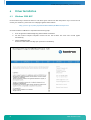
4.1
Windows 2000 & XP
On the Product CD you will find all the tools and drivers you’ll need to work with the product. If you are unsure how
current your software is, please visit our homepage to get the latest releases!
http://www.kc-ag.ch/index.php?id=drivers&dir=SMX945/XP-W2k&mountpoint=43
A correct installation of Windows is required for the following steps.
12
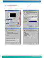
1.
Close all applications before beginning with the driver installation!
2.
Put the Kontron Compact Computers Product CD into the CD-drive. The start menu should appear
automatically.
3.
Select: DRIVERS/XP_W2k
If there is no menu then manually open up the CD on the desktop.
www.kontron.com
smartModule Express SMX945 / Driver Installation
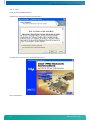
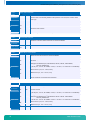
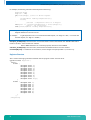
4.1.1 Chipset
Driver: x:\drivers\SMX945\chipset\
Double click on setup.exe and follow the instructions:
Reboot the system after installation.
Warning: Since version V1.1 of the SMX945, the chipset driver 8.3.1.1009 for XP and Vista must be installed.
4.1.2 VGA
Driver: x:\drivers\SMX945\VGA
Double click on setup.exe; follow the instructions:
Reboot the system after the installation.
Warning: Since version V1.1 of the SMX945, the VGA driver 6.14.10.4906 for XP (driver packet 14.32.3) or
7.14.10.1409 for Vista (driver packet 15.7), or newer, must be installed.
13
www.kontron.com
smartModule Express SMX945 / Driver Installation
4.1.3 LAN
Driver: x:\drivers\SMX945\Ethernet
Double click on setup.exe and follow the instructions:
Or double click on autorun.exe and follow the instructions:
Click "Install Drivers".
14
www.kontron.com
smartModule Express SMX945 / Driver Installation
4.1.4 AC97 Sound
Driver: x:\drivers\SMX945\Audio
Double click on setup.exe and follow the instructions:
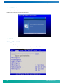
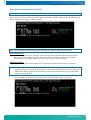
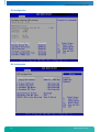
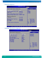
4.1.5 RAID
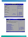
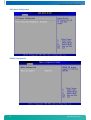
Enabling RAID in the BIOS
Use the following steps to enable RAID in the system BIOS:
15
1.
Press the <F1> key after the Power-On-Self-Test (POST) memory test begins.
2.
Select the "Advanced" menu, then the "IDE Configuration" menu:
www.kontron.com
smartModule Express SMX945 / Driver Installation
16
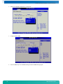
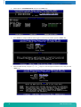
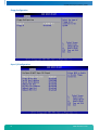
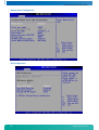
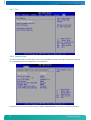
3.
Switch the "ATA/IDE Configuration" to Enhanced.
4.
Configure SATA as RAID:
5.
Press the <F10> key to save the BIOS settings and exit the BIOS Setup program.
www.kontron.com
smartModule Express SMX945 / Driver Installation
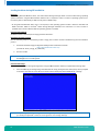
Intel® Matrix Storage Manager option ROM
Note:
This manager is only available when at least two SATA HDDs are connected!
To enter the Intel® Matrix Storage Manager option ROM user interface, press the <Ctrl> and <I> keys simultaneously
when prompted during the Power-On Self Test (POST).
Note:
The hard drive(s) and hard drive information listed for your system can differ from the example.
Version Identification
To identify the specific version of the Intel® Matrix Storage Manager option ROM integrated into the system
BIOS, enter the option ROM user interface. The version number is located in the top right corner with the
following format: vX.Y.W.XXXX, where X and Y are the major and minor version numbers.
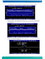
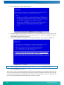
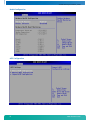
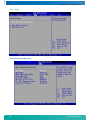
RAID Volume Creation
Use the following steps to create a RAID volume using the Intel® Matrix Storage Manager user interface:
Note:
1.
17
The following procedure should only be used with a newly-built system or if you are reinstalling your
operating system. It should not be used to migrate an existing system to RAID 0. If you wish to create matrix
RAID volumes after the operating system software is loaded, they should be created using the Intel® Matrix
Storage Console in Windows.
Press the <Ctrl> and <I> keys simultaneously when the following window appears during POST:
www.kontron.com
smartModule Express SMX945 / Driver Installation
18
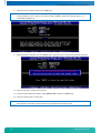
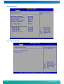
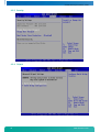
2.
Select option 1. Create RAID Volume and press the <Enter> key:
3.
Press <Enter> to accept the default name or type in a volume name and then press the <Enter> key.
4.
Select the RAID level by using the < ↑ > or < ↓ > keys to scroll through the available values, then press the
<Enter> key.
www.kontron.com
smartModule Express SMX945 / Driver Installation
19
5.
Press the <Enter> key to select the physical disks. A dialog box similar to the following will appear:
6.
Select the appropriate number of hard drives by using the < ↑ > or < ↓ > keys to scroll through the list of
available hard drives. .Press the <Space> key to select a drive. When you have finished selecting hard drives,
press the <Enter> key.
7.
Unless you have selected RAID 1, select the strip size by using the < ↑ > or < ↓ > keys to scroll through the
available values, then press the <Enter> key.
www.kontron.com
smartModule Express SMX945 / Driver Installation
8.
Note:
9.
Select the volume capacity and press the <Enter> key.
The default value indicates the maximum volume capacity using the selected disks. If less than the maximum
volume capacity is chosen, creation of a second volume is needed to utilize the remaining space (i.e., a
matrix RAID configuration).
At the Create Volume prompt, press the <Enter> key to create the volume. The following prompt will appear:
10. Press the <Y> key to confirm volume creation.
11. To exit the option ROM user interface, select option 5. Exit and press the <Enter> key.
12. Press the <Y> key again to confirm exit.
Note:
20
To change any of the information before the volume creation has been confirmed, you must exit the Create
Volume process and restart it. Press the <Esc> key to exit the Create Volume process.
www.kontron.com
smartModule Express SMX945 / Driver Installation
Loading the driver during OS installation
Overview
Unless using Microsoft Windows Vista*, the Intel® Matrix Storage Manager driver must be loaded during operating
system installation using the F6 installation method. This is required in order to install an operating system onto a
hard drive (when in AHCI mode) or RAID volume (when in RAID mode).
* If using Microsoft Windows Vista, this is not required, as the operating system includes a driver for the AHCI and
RAID controllers. Refer to the Intel® Matrix Storage Manager Installation for instructions on how to install an
updated version of the software after the operating system is installed.
F6 Installation Method
The F6 installation method requires a floppy with the driver files.
Automatic F6 Floppy Creation
Use the following steps to automatically create a floppy that contains the files needed during the F6 installation
process:
1.
Download the latest Floppy Configuration Utility from the Intel download site:
http://downloadcenter.intel.com/
(Product CD: Driver_Floppy_XP_32Bit.exe)
2.
Run the .exe file.
Note:
Use F6flpy32.exe on a 32bit system.
Use F6flpy64.exe on a 64bit system.
F6 Installation Steps
To install the Intel® Matrix Storage Manager driver using the F6 installation method, complete the following steps:
1.
Note
21
Press the <F6> key at the beginning of the Windows XP setup (during the text-mode phase) when prompted
in the status line with the "Press F6 if you need to install a third party SCSI or RAID driver" message.
After pressing F6, nothing will happen immediately; setup will temporarily continue loading drivers and then
you will be prompted with a screen to load support for mass storage device(s).
www.kontron.com
smartModule Express SMX945 / Driver Installation
2.
Press the <Z> key to specify an additional device.
3.
Insert the floppy disk containing the driver files when you see the following prompt: "Please insert the disk
labeled Manufacturer-supplied hardware support disk into Drive A:" and press the <Enter> key. Refer to
Automatic F6 Floppy Creation for instructions.
4.
Select the "Intel® 82801GHM SATA RAID Controller (Mobile ICH7MDH)" entry and press the <Enter> key.
Note:
5.
Not all available selections may appear in the list; use the < ↑ > or < ↓ > to see additional options.
Press the <Enter> key to confirm.
At this point, you have successfully F6 installed the Intel® Matrix Stoage Manager driver and Windows XP setup should
continue. Leave the floppy disk in the floppy drive until the system reboots itself because the Windows setup will need
to copy the files again from the floppy to the Windows installation folders. After Windows setup has copied these files
again, remove the floppy diskette so that Windows setup can reboot as needed.
22
www.kontron.com
smartModule Express SMX945 / Driver Installation
Intel® Matrix Storage Manager Installation
The description to install the Intel® Matrix Storage Manager under Windows, can be found on the website:
http://www.intel.com/support/chipsets/imsm/sb/CS-020670.htm
4.2
Display Driver and Control Panel
Start / Control Panel / Appearance and Themes / Display Properties / Settings tab
Enter the following settings:
23
www.kontron.com
smartModule Express SMX945 / Driver Installation
24
www.kontron.com
smartModule Express SMX945 / Driver Installation
4.3
AC97 Sound Driver and Control Panel
Sound Settings:
25
www.kontron.com
smartModule Express SMX945 / Driver Installation
4.4
SpeedStep
4.5
SpeedStep Performance Control
The Pentium-M improved the SpeedStep mechanism by adding a third power scheme in addition to the low-power and
the full-performance modes. This new mode is called adaptive mode, and allows the frequency and voltage to switch
according to the CPU activity. The CPU uses a low-power mode by default, but when its activity increases, it switches
itself very quickly into full-performance mode. This new power scheme is very pleasant to use, because it allows full
CPU speed only when needed. Of course, power consumption depends on the CPU activity, and the more the CPU is
used, the more it consumes power.
Windows XP Power Schemes
Home/Office Desktop
Portable/Laptop
Presentation
Always On
Minimal Power Management
Maximum Battery
AC Power
(Frequency example:
Mobile Pentium-M 2GHz)
None (2 GHz Always)
Adaptive (800 MHz <…>2 GHz
Adaptive (800 MHz <…>2 GHz
None (2 GHz Always)
Adaptive (800 MHz <…>2 GHz
Adaptive (800 MHz <…>2 GHz
Battery DC
(Frequency example:
Mobile Pentium-M 1.6GHz)
Adaptive (600 MHz <…>1.6 GHz
Adaptive (600 MHz <…>1.6 GHz
Degrade (600 MHz)
None (1.6 GHz Always)
Adaptive (600 MHz <…>1.6 GHz
Degrade (600 MHz)
CPU performance is heavily dependent on the choice of power scheme in the system control.
26
www.kontron.com
smartModule Express SMX945 / Driver Installation
4.5.1 Set up Power Management
Start / Control Panel / Appearance and Themes / Display Properties / Screen Saver tab
Enter the following settings:
27
click the "Power…" button
www.kontron.com
smartModule Express SMX945 / The Special Function Interface (SFI)
5
The Special Function Interface (SFI)
All functions are performed by starting the SW Interrupt 15hex with the following arguments:
5.1
INT15h SFR Functions
Function
WRITE TO EEPROM
Number
E0h
Description
Input values
AH
AL
BX
CL
SI
78h
E0h
Output value
Function
READ FROM EEPROM
Number
Description
E1h
Reads the data byte into the addressed User-Memory-Cell of the serial EEPROM.
DLAG Int15 function
Function request
Address in the EEPROM (0-1024 possible)
1234h User-Password (DLAG-Password for access to the DLAG-Memory-Cells)
Data byte
Output value
AH
AL
BX
SI
AL
Function
WRITE SERIAL NUMBER
Number
E2h
Input values
78h
E1h
Writes the data byte into the addressed User-Memory-Cell from the serial EEPROM. The old
value is automatically deleted.
DLAG Int15 function
Function request
Address in the EEPROM (0-1024 possible)
Data byte to store
1234h User-Password (otherwise EEP is write-protected)
None, all registers are restored when reopened.
Description
Input values
AH
AL
BX,
CX,
DX
SI
78h
E2h
Writes the serial number from the serial EEPROM into the addressed DLAG-Memory-Cell.
The old value is automatically deleted.
DLAG Int15 function
Function request
Serial number
Password
None, all registers are restored when reopened.
Output value
Function
READ SERIAL NUMBER
Number
Description
E3h
Input values
Output values
28
AH
AL
BX,
CX,
DX
78h
E3h
Reads the serial number from the board into the serial EEPROM.
DLAG Int15 function
Function request
Serial number (binary, not ASCI)
www.kontron.com
smartModule Express SMX945 / The Special Function Interface (SFI)
Function
WRITE PRODUCTION DATE
Number
E4h
Description
Input values
AH
AL
BX,
CX
CL
DI
SI
78h
E4h
Writes the production date into the addressed DLAG-Memory-Cell from the serial EEPROM.
The old value is automatically deleted. If the password is also in DX, the counters will be
reset (=0).
DLAG Int15 function
Function request
Production date
Day of month (1-31)
Password (clear counter)
Password
None, all registers are restored when reopened.
Output value
Function
READ PRODUCTION DATE
Number
Description
E5h
Input values
Output values
AH
AL
BX,
CX
78h
E5h
Reads the production date from the board in the serial EEPROM.
DLAG Int15 function
Function request
Production date
Function
WRITE INFO 2 TO THE EEPROM
Number
Description
E8h
AH
AL
SI
78h
E8h
DI
Input values
BH,
BL
CH,
CL
DH
DL
Writes the information bytes into the serial EEPROM.
DLAG Int15 function
Function request
Password
CPU type bits 1-7 and board type bits 8-15.
CPU type: 01h=ELAN300/310, 02h=ELAN400, 05h=P5, 08h=P3, 09h=ELAN520,
10h=P-M / BOARD TYPE
('M'=PC/104, 'E'=Euro, 'W'=MSWS, 'S'=Slot, 'C'=Custom, 'X'= smartCore or smartModule)
Board version (i.e., V1.5 BH=1, BL=5)
BIOS version (i.e., V3.0 CH=3, CL=0)
Number of 512K FLASH
Number of 512K SRAM
None, all registers are restored when reopened.
Output value
Function
READ INFO 2 FROM THE EEPROM
Number
Description
E9h
Input values
AH
AL
AL
DI
Output values
29
BH,
BL
CH,
CL
DH
DL
78h
E9h
Reads the information bytes out of the serial EEPROM.
DLAG Int15 function
Function request
Board type BOARD TYPE
('M'=PC/104, 'E'=Euro, 'W'=MSWS, 'S'=Slot, 'C'=Custom, 'X'= smartCore or smartModule)
CPU type bits 1-7 and board type bits 8-15.
CPU type: 01h=ELAN300/310, 02h=ELAN400, 05h=P5, 08h=P3, 09h=ELAN520,
10h=P-M / BOARD TYPE
('M'=PC/104, 'E'=Euro, 'W'=MSWS, 'S'=Slot, 'C'=Custom, 'X'= smartCore or smartModule)
Board version (i.e., V1.5 BH=1, BL=5)
BIOS version (i.e., V3.0 CH=3, CL=0)
Number of 512K FLASH
Number of 512K SRAM
www.kontron.com
smartModule Express SMX945 / The Special Function Interface (SFI)
Function
READ INFO 3 FROM THE EEPROM (READ COUNTER – LOW 2 BYTE OF 3 BYTE COUNTER)
Number
Description
EAh
Input values
Output values
AH
AL
AX
BX
CX
DX
78h
EAh
Function
WATCHDOG
Number
EBh
Description
Enables strobes and disables the Watchdog. After power-up, the Watchdog is always
disabled. Once the Watchdog has been enabled, the user application must perform a strobe
at least every 800ms, otherwise the Watchdog performs a hardware reset.
DLAG Int15 function
Function request
Disable
Enable
01h-FFh enable Watchdog / retrigger
Strobe
00h=BL number of seconds / 01h=BL number of minutes
Watchdog timer time-out occurred.
Output value
AH
AL
BL
BL
BL
BH
AL
Function
READ TEMPERATURE OF THE CPU
Number
Description
ECh
Input values
Input values
Output values
5.2
AH
AL
BL
CL
DX
78h
EBh
00h
01h
FFh
Reads the information bytes out of the serial EEPROM.
DLAG Int15 function
Function request
Number of boot errors
Number of setup entries
Number of low battery errors
Number of power-on starts
01h
78h
ECh
Reads the temperature from the LM75 or CPU thermal sensor.
DLAG Int15 function
Function request
00h value OK, otherwise error
ADM1023 temp bit 7=01h neg./*1C
CPU temp (from the ADM1023) bit 10=01h neg./*0125C
Int15 Emulator Driver for Windows
5.2.1 Int15 Hardware
Resources:
1.
EEPROM:
000h-3FFh:
400h-7FFh:
2K size
reserved
available for user data
2.
Temperature sensor
3.
Watchdog hardware
Access to these resources under DOS can be provided by INT 15h function, see Section 7.1.
Access under Windows 98, ME, 2000 and XP can be provided by the "Int15dl"-WDM driver; under Windows-NT with the
"Int15dl"-NT driver.
You’ll find the driver on the Product CD under x:\TOOLS\DL-INT15_Tool or in the download area of the support center:
http://www.kcc-ag.ch/index.php?id=tools&dir=/SMX945&mountpoint=44
30
www.kontron.com
smartModule Express SMX945 / The Special Function Interface (SFI)
5.2.2 Int15 Windows Software
» WinInt15.exe (Int15 function test tool)
» T945.exe (Temperature sensor [SMBUS] monitor)
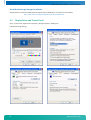
5.2.3 Driver Installation W2k/XP
"Int15dl" is not a plug-and-play driver, it must be installed manually:
1.
Open "Control Panel".
2.
Double click on "Add/Remove Hardware".
3.
To continue click the "Next>" button.
4.
On the page "Choose a Hardware Task", check "Add/Troubleshoot a device" and click "Next>".
5.
After "New hardware detection", an automatic Windows procedure, choose "Add a new device" item and
click the "Next>" button.
6.
On the "Find New Hardware" page, choose "No, I want to select the hardware from a list" and click "Next>".
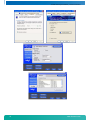
7.
Choose "Other devices" in the "Hardware Type" list and click the "Next>" button.
8.
On the page "Select a Device Driver" press the "Have Disk..." button and find the driver location
(Int15dl.inf-WDM). After opening the "inf" file, the installation program will show a Models list and
"DIGITAL-LOGIC INT15 functions emulator" string. Press the "Next>" button.
9.
Then press the "Finish" button. It is not necessary to restart the computer after installation.
10. After installation, please, be sure, that "DIGITAL-LOGIC INT15 functions emulator" has been installed
properly. Open "Control Panel", then double click on the "System" icon. Choose the "Hardware" tab and
click on the "Device Manager" button. Expand "System Devices" and double click on "DIGITAL-LOGIC INT15
functions emulator". Be sure that device is working properly.
5.2.4 Driver Installation Windows-NT
1.
Boot with administrative privileges.
2.
Copy NT-driver "Int15dl.sys" into WINNT/System32/drivers folder.
3.
Register the driver by double clicking on the "int15dl.reg" file.
4.
Reboot the computer.
5.2.5 Programming Int15dl Interface under Windows
Programming of the Int15dl interface is very similar to DOS programming and is based on the DeviceIO control
function, which operates with a pre-defined structure named "Registers".
Files:
Int15srv.h:
Int15dlioctl.h:
Test_Int15dl.cpp:
contains definitions for the Registers structure.
contains definitions for the IO control code constants.
sample subroutines providing access to hardware functions over the Int15dl driver
Functions (Test_Int15dl.cpp)
bool Int15(Registers *Regs): the main function, which sends user requests to the driver.
Returns true if the request finished successfully, otherwise it returns false.
Regs: address of the Registers structure containing specific request data (defined in Int15srv.h).
31
www.kontron.com
smartModule Express SMX945 / The Special Function Interface (SFI)
For example, the following code will initiate temperature measuring:
Registers Regs;
Regs.ah = 0xEC;
if(!Int15(&Regs)) //error in driver request
{
printf("Error reading temperature\n");
return;
}
//success - temperature value is in Regs.al
if(Regs.bl == 0)printf("\tTemperature = %d C\n",Regs.al);
//error - not valid value
else printf("\tError reading Temperature\n");
Note:
Input and output arguments of the Int15 function differ for the various chipsets and BIOSes. Read about the
Registers definition in the user manual.
For example:
To get temperature value on a board with the PIIX4 chipset, use "Regs.ah = 0xEC;" on a board with
the ICH4 chipset, use "Regs.ax = 0x78EC;".
bool Open_Int15dl(void): the first function and must be called to create a link between the "DIGITAL-LOGIC INT15
functions emulator" driver and the user software.
Returns true if the device was successfully opened, otherwise it returns false.
void Close_Int15dl(void): the last function; it breaks the link between the driver and user software.
int GetChipID(void): an additional service function; returns the type of chipset (for PIIX4 = 4, for ICH4 = 5).
Registers Structure
This is used for exchanging information between the user program and the "Int15dl" driver.
typedef struct Registers {
union {
struct {
unsigned short ax;
unsigned short bx;
unsigned short cx;
unsigned short dx;
unsigned short bp;
unsigned short si;
unsigned short di;
unsigned short ds;
unsigned short es;
unsigned short flags;
};
struct {
unsigned char al;
unsigned char ah;
unsigned char bl;
unsigned char bh;
unsigned char cl;
unsigned char ch;
unsigned char dl;
unsigned char dh;
};
};
} TRegisters;
32
www.kontron.com
smartModule Express SMX945 / The Special Function Interface (SFI)
Information for Advanced Users
At the first call of the function Open_Int15dl(), the Int15dl driver tries to detect the type of chipset. To disable this
procedure the user must define the following parameters in the "Int15dl.inf" file before installation of the driver:
For PIIX4 chipset:
HKR, "Parameters", "chipID", 0x00010001, 0x4
HKR, "Parameters", "pmBase", 0x00010001, 0x1000
HKR, "Parameters", "smbBase", 0x00010001, 0x1040
HKR, "Parameters", "tsaddr", 0x00010001, 0x9E - LM75 sensor address
For ICH4 chipset:
HKR, "Parameters", "chipID", 0x00010001, 0x5
HKR, "Parameters", "pmBase", 0x00010001, 0x1000
HKR, "Parameters", "smbBase", 0x00010001, 0x1880
HKR, "Parameters", "tsaddr", 0x00010001, 0x9C - ADM1023 sensor address
For more information, please get in contact with the Kontron Compact Computers support department.
33
www.kontron.com
smartModule Express SMX945 / Memory Specification
6
Memory Specification
This chapter describes the SMX945 system memory interface for DDR2 memory. The SMX945 supports only DDR2
memory and either one of the following SODIMMs.
» Dual Channel Asymmetric for DDR2 400/533/667 MHz devices
» Dual Channel Symmetric for DDR2 400/533/667 MHz devices
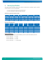
System Memory Organization Support for DDR2
Technology
256Mbit
256Mbit
512Mbit
512Mbit
1Gbit
1Gbit
Width
Page Size
Banks
X8
X16
X8
X16
X8
X16
8k
4k
8k
8k
8k
8K
4
4
4
4
8
8
Smallest Increments
256MB
128MB
512MB
256MB
1GB
512MB
512MB
256MB
1GB
512MB
2GB
1GB
Maximum Capacity
(1 DS SODIMM)
512MB
256MB
1GB
512MB
2GB
1GB
Page Size
Rank Size
4k
8k
8k
16 k
8k
8k
16 k
8k
8k
128MB
256MB
256MB
512MB
512MB
512MB
1GB
512MB
1GB
Largest Increments
DDR2 Supported Configurations
Technology
Configuration
256Mbit
256Mbit
512Mbit
512Mbit
512Mbit
1Gbit
1Gbit
1Gbit
1Gbit
16M X 16
32M X 8
32M X 16
64M X 8
64M X 8
64M X 16
128M X 8
64M X 16
128M X 8
# of Rows
# of Columns
# of Banks
Address Bits
Address Bits
Address Bits
13
13
13
13
14
14
14
13
14
9
10
10
11
10
10
11
10
10
2
2
2
2
2
2
2
3
3
Supported SO-DIMM types:
GMCH supports DDR2-SDRAM 200pin up-buffered SODIMMs specified in the JEDEC DDR2 SODIMM specification:
34
Non-ECC, single-sided,
x 16 width
Non-ECC, single-sided,
x 8 width
Non-ECC, double-sided,
x 16 width
Non-ECC, double-sided,
x 8 width (stacked)
www.kontron.com
smartModule Express SMX945 / Software
7
Software
7.1
Windows Int15 Tool
The tool and driver are on the Product CD under x:\TOOLS\DL-INT15_Tool or in the download area of the support
center:
http://www.kcc-ag.ch/index.php?id=tools&dir=/SMX945&mountpoint=44
7.1.1 Int15 Windows Software
WinInt15.exe (Int15 function test tool)
T945.exe (Temperature sensor [SMBUS] monitor)
35
www.kontron.com
smartModule Express SMX945 / Software
7.2
Remote Control over COM Port
7.2.1 Requirements
Serial Null-Modem cable (only RX and TX)
Remote computer: Serial port COM1 or COM2
Host computer: Serial port COM1 or COM2, OS (Windows or MSDOS [FREEDOS]), floppy image file with MSDOS 6.22
or FREEDOS
7.2.2 Limitations
» OS on the Remote computer: MSDOS or FREEDOS.
» Enabling "remote floppy" support will disable all other floppy disks on the remote computer.
» Because of the compatibility mode with PC ANSI and VT-100 protocol, remote keyboard doesn't support the
Alt key and some SHIFT/Ctrl key combinations.
7.2.3 Principles of Functionality
The serial port on the remote computer works in asynchronous mode with an enabled hardware interrupt.
The remote console gets a depressed key on the host computer and transmits it to the remote computer over a serial
link where it is received and stored into the keyboard buffer. From the other side, the TSR serial port routine makes a
buffer of the screen information and periodically scans screen memory to find any changes. These changes are sent via
serial link to the host console program.
Emulation of the floppy works in synchronous mode. The remote BIOS routine hooks the INT13(disk) vector. When the
OS asks for remote disk access, the serial port TSR halts keyboard and video support, sends a special request to the
host computer and waits until this request is supported before restoring the keyboard/video asynchronous protocol.
Windows application RemoteSMX945.exe
36
www.kontron.com
smartModule Express SMX945 / Software
MSDOS application remSMX945.exe
The remote console application must be loaded and connected before the BIOS start on the remote computer. The
supported option"Floppy…" must be chosen before connecting. The remote application simulates floppy disk access
over the "floppy image file"; this image file can be modified with, for example, WinImage software
http://www.winimage.com/winimage.htm. It is also possible to use Flimfex11.exe from Kontron Compact Computers'
remote software package. (Flimfex = floppy image file explorer)
R – this button sends a request to the remote computer TSR routine to refresh on-screen information on the host
computer.
Options for an MSDOS application can be changed in the REMSM945.INI file.
PORT=1: Use COM1 for remote control on the host computer.
FLOPPY=FREEDOS2.IMG: Enable remote floppy and use FREEDOS2.IMG image file for floppy disk emulation.
Note:
All remote features are supported only under FREEDOS or MSDOS 6.22.
7.2.4 Hardware Settings on the Remote Computer
To enable a remote COM port for remote control:
1.
Press DEL at boot time to enter the BIOS setup
2.
Enter "Advanced"
3.
Enter "Remote Access Configuration"
4.
Set COM port parameters and required protocol parameters
Note:
37
On the host side, it is possible to use any terminal emulation software which supports PC ANSI or VT100
protocol.
www.kontron.com
smartModule Express SMX945 / Software
Note:
Remote floppy support works under the following conditions:
1.
2.
3.
4.
5.
6.
7.
Note:
Remote console software is DIGITAL-LOGIC Remote945.exe
Serial Port Mode
[115200 8,n,1]
Flow Control
[None]
Redirection after BIOS POST
[Remote Floppy Enabled] – not for the SMX945B-N270
Terminal Type
[ANSI]
VT-UTF8 Combo Key Support
[Enabled]
Terminal Size
[80 X 25]
When the remote floppy option is enabled, it is impossible to use any floppy disk; even the USB floppy is not
accessible.
7.2.5 Emulated Features
Floppy Disk: INT 13
When the remote floppy disk is enabled, all floppy disk requests will be redirected to the remote console
application; all requests to the hard disk will be executed by the native BIOS.
To make the "remote floppy disk" bootable it is necessary to make a floppy image from a bootable floppy disk.
Ctrl-Alt-Del simulation:
Windows OS hooks Ctrl-Alt-Del keys in sequence.
To send a signal from the host console to the remote computer, press Ctrl-Alt and click the on-screen "Del"
button with the mouse.
38
www.kontron.com
smartModule Express SMX945 / Diagnostics
8
Diagnostics
8.1
AMIBIOS8™ Check Point Lists for the SMX945
8.1.1 Boot Block Initialization Code Checkpoints
The boot block initialization code sets up the chipset, memory and other components before the system memory is
available. The following table describes the type of checkpoints that may occur during the boot block initialization
portion of the BIOS.
Note:
Checkpoints may differ between different platforms based on system configuration and may change due to
vendor requirements, system chipset or optional ROMs from add-in PCI devices.
Checkpoint
Before D0
D1
D2
D3
D4
D5
D6
D7
D8
D9
DA
DC
E1 - E8
EC - EE
39
Description
If boot block debugger is enabled, CPU cache-as-RAM functionality is enabled at this point. Stack will be enabled
from this point.
D0 Early Boot Strap Processor (BSP) initialization like microcode update, frequency and other CPU critical
initialization. Early chipset initialization is done.
Early super I/O initialization is done including RTC and keyboard controller.
Serial port is enabled at this point if needed for debugging. NMI is disabled.
Perform keyboard controller BAT test. Save power-on CPUID value in scratch CMOS.
Go to flat mode with 4GB limit and GA20 enabled.
Verify the boot block checksum. System will hang here if checksum is bad.
Disable CACHE before memory detection. Execute full memory sizing module.
If memory sizing module not executed, start memory refresh and do memory sizing in boot block code. Do
additional chipset initialization.
Re-enable CACHE. Verify that flat mode is enabled.
Test base 512KB memory. Adjust policies and cache first 8MB. Set stack.
Boot block code is copied from ROM to lower system memory and control is given to it.
BIOS now executes out of RAM. Copies compressed boot block code to memory in right segments. Copies BIOS
from ROM to RAM for faster access.
Performs main BIOS checksum and updates recovery status accordingly.
Both key sequence and OEM specific method is checked to determine if BIOS recovery is forced. If BIOS recovery is
necessary, control flows to checkpoint E0.
See section 8.1.2 for more information.
Restore CPUID value back into register. The Boot Block-Runtime interface module is moved to system memory and
control is given to it.
Determine whether to execute serial flash.
The Runtime module is uncompressed into memory. CPUID information is stored in memory.
Store the Uncompressed pointer for future use in PMM.
Copying main BIOS into memory leaves all RAM below 1MB Read-Write including E000 and F000 shadow areas but
closing SMRAM.
Restore CPUID value back into register.
Give control to BIOS POST (ExecutePOSTKernel).
See section 8.1.3 for more information.
System is waking from ACPI S3 state
OEM memory detection/configuration error. This range is reserved for chipset vendors and system manufacturers.
The error associated with this value may be different from one platform to the next.
www.kontron.com
smartModule Express SMX945 / Diagnostics
8.1.2 Boot Block Recovery Code Checkpoints
The boot block recovery code gets control when the BIOS determines that a BIOS recovery needs to occur because the
user has forced the update or the BIOS checksum is corrupt. The following table describes the type of checkpoints that
may occur during the boot block recovery portion of the BIOS.
Note:
Checkpoints may differ between different platforms based on system configuration and may change due to
vendor requirements, system chipset or optional ROMs from add-in PCI devices.
Checkpoint
Description
Initialize the floppy controller in the super I/O. Some interrupt vectors are initialized.
DMA controller is initialized. 8259 interrupt controller is initialized. L1 cache is enabled.
Set up floppy controller and data. Attempt to read from floppy.
Enable ATAPI hardware. Attempt to read from ARMD and ATAPI CDROM.
Disable ATAPI hardware. Jump back to checkpoint E9.
Read error occurred on media. Jump back to checkpoint EB.
Search for pre-defined recovery file name in root directory.
Recovery file not found.
Start reading FAT table and analyze FAT to find the clusters occupied by the recovery file.
Start reading the recovery file, cluster by cluster.
Disable L1 cache.
Check the validity of the recovery file configuration to the current configuration of the flash part.
Make flash write-enabled through chipset and OEM specific method.
Detect proper flash part. Verify that the found flash part size equals the recovery file size.
The recovery file size does not equal the found flash part size.
Erase the flash part.
Program the flash part.
The flash has been updated successfully. Make flash write disabled.
Disable ATAPI hardware. Restore CPUID value back into register.
Give control to F000 ROM at F000:FFF0h.
E0
E9
EA
EB
EF
F0
F1
F2
F3
F5
FA
FB
F4
FC
FD
FF
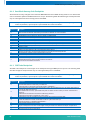
8.1.3 POST Code Checkpoints
The POST code checkpoints are the largest set of checkpoints during the BIOS pre-boot process. The following table
describes the type of checkpoints that may occur during the POST portion of the BIOS
Note:
Checkpoints may differ between different platforms based on system configuration and may change due to
vendor requirements, system chipset or optional ROMs from add-in PCI devices.
Checkpoint
03
04
05
06
07
08
C0
C1
40
Description
Disable NMI, Parity, video for EGA, and DMA controllers. Initialize BIOS, POST, and Runtime data area. Also
initialize BIOS modules on POST entry and GPNV area.
Initialized CMOS as mentioned in the Kernel Variable "wCMOSFlags."
Check CMOS diagnostic byte to determine if battery power is OK and CMOS checksum is OK. Verify CMOS checksum
manually by reading storage area.
If the CMOS checksum is bad, update CMOS with power-on default values and clear passwords. Initialize status
register A.
Initializes data variables that are based on CMOS setup questions.
Initializes both the 8259 compatible PICs in the system
Initializes the interrupt controlling hardware (generally PIC) and interrupt vector table.
Do R/W test to CH-2 count reg. Initialize CH-0 as system timer.
Install the POSTINT1Ch handler. Enable IRQ-0 in PIC for system timer interrupt.
Traps INT1Ch vector to "POSTINT1ChHandlerBlock."
Fixes CPU POST interface calling pointer.
Initializes the CPU. The BAT test is being done on KBC.
Program the keyboard controller command byte is being done after Auto detection of KB/MS using AMI KB-5.
Early CPU Init Start – Disable Cache – Init Local APIC.
Set up boot strap processor information.
www.kontron.com
smartModule Express SMX945 / Diagnostics
Checkpoint
Description
C2
C5
C6
C7
0A
0B
0C
Set up boot strap processor for POST.
Enumerate and set up application processors.
Re-enable cache for boot strap processor.
Early CPU Init Exit.
Initializes the 8042 compatible Keyboard Controller.
Detects the presence of PS/2 mouse.
Detects the presence of Keyboard in KBC port.
Testing and initialization of different Input Devices. Also, update the Kernel Variables.
Traps the INT09h vector, so that the POST INT09h handler gets control for IRQ1.
Uncompress all available language, BIOS logo, and Silent logo modules.
Early POST initialization of chipset registers.
Relocate System Management Interrupt vector for all CPUs in the system.
Uncompress and initialize any platform specific BIOS modules.
GPNV is initialized at this checkpoint.
Initializes different devices through DIM. See section 8.1.5 for more information.
Initializes different devices.
Detects and initializes the video installed in the system that have optional ROMs.
Initializes all the output devices.
Allocate memory for ADM module and uncompress it. Give control module for initialization.
Initialize language and font modules. Activate ADM module.
Initializes the silent boot module. Set the window for displaying information.
Displaying sign-on message, CPU information, setup key message, OEM specific information.
Initializes different devices through DIM. See section 8.1.5 for more information. USB controllers at this point.
Initializes DMAC-1 & DMAC-2.
Initialize RTC date/time.
Test for total memory installed in the system. Also, check for keys to limit memory test.
Display total memory in the system.
Mid POST initialization of chipset registers.
Detect different devices (parallel ports, serial ports, coprocessor CPU, etc.) successfully installed in the system
and update EBDA, etc.
Updates CMOS memory size from memory found in memory for Extended BIOS Data Area from base memory.
Programming the memory hole or any kind of implementation that needs in system RAM size if needed.
Initializes NUM-LOCK status and programs the KBD typematic.
Initialize Int-13 and prepare for IPL detection.
Initializes IPL devices controlled by BIOS and option ROMs.
Generate and write contents of ESCD in NVRam.
Log errors encountered during POST.
Display errors to the user and gets the user response for error.
Execute BIOS setup if needed / requested. Check boot password if installed.
Late POST initialization of chipset registers.
Build ACPI tables (if ACPI is supported).
Program the peripheral parameters. Enable/Disable NMI as selected.
Initialization of system management interrupt by invoking all handlers.
Please note this checkpoint comes right after checkpoint 20h
Clean-up work needed before booting to OS.
Takes care of runtime image preparation for different BIOS modules.
Fill the free area in F000h segment with 0FFh. Initializes the Microsoft IRQ Routing Table.
Prepares the runtime language module. Disables the system configuration display if needed.
Initialize runtime language module. Display boot option popup menu.
Displays the system configuration screen if enabled.
Initialize the CPUs before boot, which includes the programming of the MTRRs.
Wait for user input at config display if needed.
Uninstall POST INT1Ch vector and INT09h vector.
Prepare BBS for Int 19 boot. Init MP tables.
End of POST initialization of chipset registers. De-initializes the ADM module.
Save system context for ACPI. Prepare CPU for OS boot including final MTRR values.
Passes control to OS Loader (typically INT19h).
0E
13
20
24
2A
2C
2E
31
33
37
38
39
3A
3B
3C
40
52
60
75
78
7C
84
85
87
8C
8D
8E
90
A1
A2
A4
A7
A9
AA
AB
AC
B1
00
8.1.4 OEM POST Error Checkpoints
Checkpoints from the range 61h to 70h are reserved for chipset vendors and system manufacturers. The error
associated with this value may be different from one platform to the next.
41
www.kontron.com
smartModule Express SMX945 / Diagnostics
8.1.5 DIM Code Checkpoints
The Device Initialization Manager (DIM) takes control at various times during the BIOS POST to initialize different
system buses. The following table describes the main checkpoints where the DIM module is accessed.
Note:
Checkpoints may differ between different platforms based on system configuration and may change due to
vendor requirements, system chipset or optional ROMs from add-in PCI devices.
Checkpoint
2A
38
Description
Initialize different buses and perform the following functions:
Reset, Detect, and Disable (function 0); Static Device Initialization (function 1); Boot Output Device
Initialization (function 2).
Function 0 disables all device nodes, PCI devices, and PnP ISA cards; it also assigns PCI bus numbers.
Function 1 initializes all static devices that include manually configured onboard peripherals, memory and I/O
decode windows in PCI-PCI bridges, and non-compliant PCI devices; static resources are also reserved.
Function 2 searches for and initializes any PnP, PCI, or AGP video devices.
Initialize different buses and perform the following functions:
Boot Input Device Initialization (function 3); IPL Device Initialization (function 4); General Device
Initialization (function 5).
Function 3 searches for and configures PCI input devices and detects if the system has a standard keyboard
controller.
Function 4 searches for and configures all PnP and PCI boot devices.
Function 5 configures all onboard peripherals that are set to an automatic configuration and configures all
remaining PnP and PCI devices.
While control is in the different functions, additional checkpoints are output to port 80h as a word value to identify
the routines under execution. The low byte value indicates the main POST Code Checkpoint. The high byte is divided
into two nibbles and contains two fields. The details of the high byte of these checkpoints are as follows:
HIGH BYTE XY
The upper nibble "X" indicates the function number that is being executed. "X" can be from 0 to 7.
0 = func#0, disable all devices on the BUS concerned.
1 = func#1, static devices initialization on the BUS concerned.
2 = func#2, output device initialization on the BUS concerned.
3 = func#3, input device initialization on the BUS concerned.
4 = func#4, IPL device initialization on the BUS concerned.
5 = func#5, general device initialization on the BUS concerned.
6 = func#6, error reporting for the BUS concerned.
7 = func#7, add-on ROM initialization for all BUSes.
8 = func#8, BBS ROM initialization for all BUSes.
The lower nibble "Y" indicates the BUS on which the different routines are being executed. "Y" can be from 0 to 5.
0 = Generic DIM (Device Initialization Manager).
1 = On-board System devices.
2 = ISA devices.
3 = EISA devices.
4 = ISA PnP devices.
5 = PCI devices.
8.1.6 ACPI Runtime Checkpoints
ACPI checkpoints are displayed when an ACPI capable operating system either enters or leaves a sleep state. The
following table describes the type of checkpoints that may occur during ACPI sleep or wake events.
Note:
42
Checkpoints may differ between different platforms based on system configuration and may change due to
vendor requirements, system chipset or optional ROMs from add-in PCI devices.
www.kontron.com
smartModule Express SMX945 / Diagnostics
Checkpoint
Description
AC
AA
01, 02, 03, 04, 05
10, 20, 30, 40, 50
First ASL check point. Indicates the system is running in ACPI mode.
System is running in APIC mode.
Entering sleep state S1, S2, S3, S4 or S5.
Waking from sleep state.
8.2
AMIBIOS8™ Beep Code List for the SMX945
8.2.1 Boot Block Beep Codes
# of Beeps
Description
1
2
3
4
5
6
7
8
9
10
11
12
13
Insert diskette in floppy drive A:.
'AMIBOOT.ROM' file not found in root directory of diskette in A:.
Base Memory error.
Flash Programming successful.
Floppy read error.
Keyboard controller BAT command failed.
No Flash EPROM detected.
Floppy controller failure.
BootBlock BIOS checksum error.
Flash Erase error.
Flash Program error.
'AMIBOOT.ROM' file size error.
BIOS ROM image mismatch (file layout does not match image present in flash device)
8.2.2 POST BIOS Beep Codes
# of Beeps
Description
1
2
3
4
5
6
7
8
9
10
11
12
13
Memory refresh timer error.
Parity error in base memory (first 64KB block)
Base memory read/write test error
Motherboard timer not operational
Processor error
8042 Gate A20 test error (cannot switch to protected mode)
General exception error (processor exception interrupt error)
Display memory error (system video adapter)
AMIBIOS ROM checksum error
CMOS shutdown register read/write error
Cache memory test failed
'AMIBOOT.ROM' file size error.
BIOS ROM image mismatch (file layout does not match image present in flash device)
8.2.3 Troubleshooting POST BIOS Beep Codes
# of Beeps
Troubleshooting Action
1, 2 or 3
Reseat the memory or replace with known good modules.
Fatal error indicating a serious problem with the system. Consult your system manufacturer. Before declaring the
motherboard beyond all hope, eliminate the possibility of interference by a malfunctioning add-in card. Remove
all expansion cards except the video adapter.
• If beep codes are generated when all other expansion cards are absent, consult your system manufacturer's
technical support.
• If beep codes are not generated when all other expansion cards are absent, one of the add-in cards is causing
the malfunction. Insert the cards back into the system one at a time until the problem happens again. This will
reveal the malfunctioning card.
If the system video adapter is an add-in card, replace or reseat the video adapter. If it's an integrated part of the
system board, the board may be faulty.
4-7, 9-11
8
43
www.kontron.com
smartModule Express SMX945 / BIOS
9
BIOS
9.1
BIOS History
Vers.
Date
1.00
02.10.2006
1.01
07.11.2006
Status
Edited by
Development
Development
Modifications
Initial version from AMI
Custom logo / INT15 functions implemented
1.10
20.07.2007
Released
BRM
1.15
05.11.2007
"
BRM/VIV
1.16
1.17
10.11.2007
10.12.2007
"
Released
BRM
VIV
1.20
25.03.2008
"
BRM/VIV
1.25
13.01.2010
"
BRM/VIV
1.27
30.08.2010
Released
BRM
Initial DLAG test version with INT15 support / New VBIOS 1413 / PCI routing
table adapted to DLAG standard / Code update from AMI / INT15 fix from VIV
(serial number) / New VBIOS 1436 / CK410M clock generator CPU0, CPU1
STPCPU fix / New SREDIR module from AMI / Default settings changed /
Hardware monitor adapted / New VBIOS 1478 / Default date = Build date / Fix
for ALC882 HD_Audio Codec (adapted to DLAG boards)
SLP & SLIC support / 2nd winbond SIO added in autodetect mode / Various
files added & modified / Corrected detection of 2nd SIO resources / Corrected
multiplier and pull-up/down for DDR2 memory / Support & detection for
Intel's 945GME chipset
Modified for PIC870 feedback / Boot up process improved (E47)
Bugfix of V1.16 (can't boot w/disabled logo)
Remote floppy support over COM port added / Onboard CIR port removed /
New VBIOS 1585 / Video strings adapted / Updated logo module from AMI /
Remote Port fix.
ASL SMBUS access methods corrected / SMBUS block reading command
implemented / SMBUS smart battery support added (w/o charger) / Bugfix in
feedback to PIC with disabled logo / Function replaced to OEM.ASM / Gigabit
LAN boot extension added / Switched to dual channel RAM config for
SMX945B / Option to disable LAN boot extension in BIOS / Changed logo &
sign-on message to Kontron
Adapted SMBIOS dmi info to Kontron standard / Added 2nd codec table for
Realtek ALC888 audio codec
9.1.1 BIOS History SMX945B-N270 AMI Core8
Note:
The following BIOS History is only for the SMX945B-N270.
Vers.
Date
Status
Edited by
1.00
27.10.2009
Development
BRM
1.01
25.02.2010
Released
BRM
1.02
1.03
1.04
30.08.2010
07.12.2010
15.12.2010
Released
Released
Released
BRM
BRM
BRM
44
Modifications
Initial version for N270 SMART with INT15 support
Adapted Audio Codec verb table for ALC882 / Adapted smBIOS dmi
information to Kontron standard
Added second Codec table for Realtek ALC888 Audio Codec
Removed hardware health menu from setup / Added console redirection menu
Vixed PCIe slot definition
www.kontron.com
smartModule Express SMX945 / BIOS
9.2
Specifications of the BIOS
Embedded BIOS
Remarks
ACPI PM
ACPI Battery Support
Boot Devices
CMOS-Data
BIOS Setup Backup
V3.0 Power Management
Not enabled
PATA, SATA, USB-Devices, LAN
Battery backed SRAM and a copy in the EEPROM
Automatically written into the EEPROM after setup-screen exit
Generally possible, setup data are transferred from the EEPROM.
The system integrator is responsible for testing and validating the application software on a batteryless platform.
Without backup-battery, the time and date counter is not running while the computer system is
switched off!
Possible, must be ordered separately
Possible, must be ordered separately
Supports PCI V2.2 with up to 6 resources
Supports PCI V2.2
Trusted Platform Module, optionally connectable to the SMB-Bus
Shutdown or restart, depends on the implementation
Yes, with the ICH7M on the SMX945 RAID0 and 1 on 2x SATA
Compatible mode (IRQ14/15) or Native mode (PCI device)
Yes, Advanced Programmable Interrupt Controller
Yes, Advanced Host Controller Interface for SATA Hotplug
Yes, Enhanced Intel SpeedStep Technology
Yes, needs a processor with the Core 2 Duo
Yes, Intel Virtualization Technology, needs Core Duo or Core 2 Duo
Yes, integrated in the ACPI
Throttling processor function
Control of the fan for active cooling
Critical trip point (the OS must shut down the system asap)
Catastrophic temperature (hardware shutdown)
Supported are:
S1 (POS = Power On Suspend)
S3 (STR = Suspend to RAM)
S4 (Suspend to Disk) is not supported by the BIOS; alternatively, the Win2000 and Win XP
Operating Systems use S4-OS (Hibernate)
Battery-less Boot
Customized CMOS
Customized User Data
PCI Parallel
PCIexpress
TPM V1.2
Watchdog Support
RAID Support
IDE Mode
APIC-Support
AHCI
EIST
Intel 64
Intel VT
Thermal Management
Supported
ACPI Suspend Modes
Wakeup Events
Remarks
Power Button
GPI1#
GPI2#
WOL, LAN wake event
SMBALERT#
PCIexpress WAKE#
PME#
Wakes unconditionally from S1-S5
Only if configured as LID Switch
Only if configured as RESUME ON RING
LAN driver must be configured for WOL
Wakes up unconditionally from S1-S5
Wakes up unconditionally from S1-S5
Activates the wake-up capabilities of a PCI circuit
When standby mode S1 is set, the wake-up with USB MS/KB works. This depends on the system
implementation.
USB Mouse/KB
45
www.kontron.com
smartModule Express SMX945 / BIOS
9.3
Core BIOS Functions
INTEL Chipset Support 945GM
Remarks
GMCH Support with all timings (DDRAM , ...)
Auto-detect AGP/internal video in the GME.
Internal video BIOS only if no AGP available.
ICH Support
Password/Security
Remarks
Standard functions
TCP/IP number for FirstWare tools
(browser, download service)
Multi-boot Setup
Remarks
Boot from FD
Boot from HD
Boot from CD
Boot from USB FD
Boot from USB CD
Boot from Firewire CD
Boot from Firewire HD
Boot from LAN
Boot from DOC2000/Flashdisk
Boot from PC-Card slot A or B
USM Memory stick
Select order of boot-up
Planned
Planned
INTEL 82551E/Q
TI4520 PC Card controller
C-D-A, A-C-D, none
Serial Remote Function
Remarks
Enable/Disable/Auto-detect
select COM1 or COM2
ISA-Setup (LPC-SuperIO W83627HF)
Remarks
COM1
COM2
FD (and IRQ6)
LPT (and IRQ7)
IrDA
PS/2-Keyboard (and IRQ1)
PS/2-MS (and IRQ12)
IRQ definitions
IRQ selection
IRQ selection
Enable/disable
Enable/disable
Enable/Disable/FIR/SIR
Enable/Disable
Enable/Disable
PnP, PCI, ISA
Keyboard Settings
Remarks
Standard-like
Typematic rate, numlock status, …
Power Management
Remarks
ACPI Functions
APM Function
AC-Full speed CPU Frequency select
Battery-Speed CPU Frequency select
Trottle temperature
Trottle function
Other thermal protection features of the
PENTIUM-M
Wake on LAN
Suspend to RAM (S3)
Suspend to Disk (S4)
Communication over SMB with the
PIC-PM-Controller for Wake-up/Suspend
AC-Detect for full speed
46
600/800/1000/1200/1400/1600/Max/ MHz
600/800/1000/1200/1400/1600/Max/ MHz
60°C – 100°C in steps of 5°
enabled /disabled
Enable/Disable, setting of the TCP/IP number
Planned
No AC means Battery-mode speed
www.kontron.com
smartModule Express SMX945 / BIOS
Wake Events
Remarks
LAN activity
KB activity
MS activity
LID
Active ring signal
PWRBTN#
Time-controlled wake-up
Possibly solved in the PIC Controller
Suspend Events
Remarks
PWRBTN# (S2R or S2D)
No activity over a defined time
Software controlled shutdown
PIC Microcontroller
Select time from 1-255 minutes
SmartBattery down
PIC Microcontroller
0%, 5%, 10%, 15%, 20%, off
(SMB-detect of LTC1779)
Time-controlled suspend
Fast Boot
Remarks
Normal
Fast boot
Failure activity
Boot counter
15-25sec = normal boot
10-15sec = quick boot
No-Wait, Wait and error display, No-Wait and counter in the EEPROM
Enabled/Disabled (in the EEPROM)
Screen
Remarks
Boot-up screen
Start-up resolution in the BIOS
Boot-up logo
CRT1, Dual, DVO, LVDS-A
640x480, 600x800, 1024x768
Enable/Disable
For Realtime Operating Systems
Remarks
HotPlug-Service
USB-HotPlug Service
Enable/Disable
Enable/Disable
Battery-less BIOS-Setup
Remarks
Automatic save/reload of the EEPROM values
INT15 services
If battery fails
Download Functions
Remarks
Core/VGA BIOS download
DOS / Windows
Supply Monitor
Remarks
Display all power supplies of the W83627HF
Display fan speed
Fan control
Definition of the threshold of supply and speed
Activity in case of failure
Enable/Disable
5%, 10%, 20%
Power-off, suspend, slow speed, trottle mode
WatchDog (planned)
Remarks
WatchDog
Time out
Enable/Disable
1, 10, 20, 30, 40, 50, 60 sec, 2, 3, 4, 5-32min
47
www.kontron.com
smartModule Express SMX945 / BIOS
9.4
Core BIOS Download
Before downloading a BIOS, please check the following:
Make a bootable diskette which includes the following files:
» DELEP945.exe
» afudos.exe
» core BIOS ()
Rename the DLAG_xxx.ROM file to bios.rom
IMPORTANT:
Notes:
»
»
»
»
»
Do not use boot disks created in a Windows operating system. If you do not have an MSDOS 6.22 disk
available, you can download a boot disk from www.bootdisk.com.
Disable the EMM386 or other memory managers in the CONFIG.SYS of your boot disk.
Make sure that the AFUDOS.exe program and the BIOS to be downloaded are in the same path and
directory!
Boot DOS without config.sys and autoexec.batpress F5 while starting the DOS boot.
Is the empty disk space, where the AFUDOS.exe is located, larger than 64kB (for safe storage)?
Is the floppy disk not write-protected?
Start the DOWNLOADING process:
1.
Start the system with the bootable diskette. If you do not have a bootable diskette or floppy drive you can
start in DOS mode by pressing the F5 key to disable the autoexec.bat and config.sys.
2.
Run DELEP945.exe to clear the CMOS and the EEPROM.
Warning
If you do not run DELEP945.exe, the system will be destroyed during the BIOS upgrade!
3.
Run AFUDOS.EXE BIOS.ROM /X /B /P
4.
If the BIOS download is finished, you must power off the system.
5.
After powering the system back on, press DEL to enter the setup mode and set the default values with F9.
6.
"Save and leave" the setup with F10.
7.
Power off the system.
8.
The download procedure is finished.
9.5
BIOS Setup
Setup Menu Screens and Navigation
Keystroke Controls:
Function
Key
Enter Setup
Load AMIBIOS "Failsafe" CMOS Setup Values
Display extra AMIBIOS Information at Boot
Switch between AMIBIOS "Silent Boot" graphical
logo and standard text boot screen
Boot from Network Device
Enter Setup after System Error
Load CMOS Setup Defaults after System Error
Initiate BIOS Recovery & clear CMOS
Initiate BIOS Recovery, clear CMOS & NVRAM
Initiate BIOS Recovery, preserve CMOS & NVRAM
Pop-Up Boot Menu
Enter Setup (for Serial Console Redirection)
Activate AMIKey Recovery Boot Services
DEL
END
INS
48
TAB
F12
F1
F2
CTRL-HOME
CTRL-PGUP
CTRL-PGDN
F8 or F11
F3
F9
www.kontron.com
smartModule Express SMX945 / BIOS
9.5.1 Main Menu
9.5.2 Advanced
49
www.kontron.com
smartModule Express SMX945 / BIOS
CPU Configuration
IDE Configuration
50
www.kontron.com
smartModule Express SMX945 / BIOS
Floppy Configuration
Super I/O Configuration
51
www.kontron.com
smartModule Express SMX945 / BIOS
Health Configuration
ACPI Configuration
52
www.kontron.com
smartModule Express SMX945 / BIOS
APM Configuration
Event Log Configuration
53
www.kontron.com
smartModule Express SMX945 / BIOS
INTEL AMT Configuration
MPS Configuration
54
www.kontron.com
smartModule Express SMX945 / BIOS
PCI Express Configuration
SMBIOS Configuration
55
www.kontron.com
smartModule Express SMX945 / BIOS
Remote Access Configuration
USE Configuration
56
www.kontron.com
smartModule Express SMX945 / BIOS
9.5.3 PCI PnP
57
www.kontron.com
smartModule Express SMX945 / BIOS
9.5.4 Boot
Boot Settings Configuration
58
www.kontron.com
smartModule Express SMX945 / BIOS
9.5.5 Security
9.5.6 Chipset
59
www.kontron.com
smartModule Express SMX945 / BIOS
Northbridge Configuration
Northbridge / Video Function Configuration
60
www.kontron.com
smartModule Express SMX945 / BIOS
Southbridge Configuration
61
www.kontron.com
smartModule Express SMX945 / BIOS
9.5.7 Exit
9.5.8 Remote Access
Use a Null-modem cable to connect COM1 or COM 2 of the embedded computer to the COM1 or COM2 port of the host
PC. In the BIOS setup you can configure the console redirection:
On the host PC, you must start a terminal program (MSDOS or WINDOWS) which is able to show a minimum of 25 lines.
62
www.kontron.com
smartModule Express SMX945 / BIOS
9.6
CMOS RAM Map
Systems based on the industry-standard specification include a battery backed real-time clock (RTC) chip. This clock
contains at least 64 Bytes of non-volatile RAM. The system BIOS uses this area to store information including system
configuration and initialization parameters, system diagnostics, and the time and date. This information remains
intact even when the system is powered down.
The BIOS supports 128 Bytes of CMOS RAM. This information is accessible through I/O ports 70h and 71h. CMOS RAM
can be divided into several segments:
» Locations 00h-0Fh contain the RTC and status information
» Locations 10h-2Fh contain system configuration data
» Locations 30h-3Fh contain system BIOS-specific configuration data as well as chipset-specific information
» Locations 40h-7Fh contain chipset-specific information as well as power management configuration
parameters
The following table provides a summary of how these areas may be further divided.
Beginning
Ending
Checksum
Description
00h
10h
2Eh
30h
34h
40h
5Ch
5Eh
6Fh
7Eh
0Fh
2Dh
2Fh
33h
3Fh
5Bh
5Dh
6Eh
7Dh
7Fh
No
Yes
No
No
No
Yes
No
No
Yes
No
RTC and Checksum
System Configuration
Checksum Value of 10h-2Dh
Standard CMOS
Standard CMOS - SystemSoft Reserved
Extended CMOS - Chipset Specific
Checksum Value of 40h-5Bh
Extended CMOS - Chipset Specific
Extended CMOS - Power Management
Checksum Value of 6Fh-7Dh
CMOS Map
Location
Description
00h
01h
02h
03h
04h
05h
06h
07h
08h
09h
0Ah
Time of day (seconds) specified in BCD
Alarm (seconds) specified in BCD
Time of day (minutes) specified in BCD
Alarm (minutes) specified in BCD
Time of day (hours) specified in BCD
Alarm (hours) specified in BCD
Day of week specified in BCD
Day of month specified in BCD
Month specified in BCD
Year specified in BCD
Status Register A
Bit 7
=
Update in progress
Bits 6-4 =
Time based frequency divider
Bits 3-0 =
Rate selection bits that define the periodic interrupt rate and output frequency.
63
www.kontron.com
smartModule Express SMX945 / BIOS
CMOS Map
Location
Description
0Bh
Status Register B
Bit 7
=
Run/Halt
0
Run
1
Halt
Bit 6
=
Periodic Timer
0
Disable
1
Enable
Bit 5
=
Alarm Interrupt
0
Disable
1
Enable
Bit 4
=
Update Ended Interrupt
0
Disable
1
Enable
Bit 3
=
Square Wave Interrupt
0
Disable
1
Enable
Bit 2
=
Calendar Format
0
BCD
1
Binary
Bit 1
=
Time Format
0
12-Hour
1
24-Hour
Bit 0
=
Daylight Savings Time
0
Disable
1
Enable
Status Register C
Bit 7
=
Interrupt Flag
Bit 6
=
Periodic Interrupt Flag
Bit 5
=
Alarm Interrupt Flag
Bit 4
=
Update Interrupt Flag
Bits 3-0 =
Reserved
Status Register D
Bit 7
=
Realtime Clock
0
Lost Power
1
Power
CMOS Location for Bad CMOS and Checksum Flags
Bit 7
=
Flag for CMOS Lost Power
0
Power OK
1
Lost Power
Bit 6
=
Flag for CMOS checksum bad
0
Checksum is valid
1
Checksum is bad
Shutdown Code
Diskette Drives
Bits 7-4 =
Diskette Drive A
0000
= Not installed
0001
= Drive A = 360 kB
0010
= Drive A = 1.2MB
0011
= Drive A = 720 kB
0100
= Drive A = 1.44MB
0101
= Drive A = 2.88MB
Bits 3-0 =
Diskette Drive B
0000
= Not installed
0001
= Drive B = 360 kB
0010
= Drive B = 1.2MB
0011
= Drive B = 720 kB
0100
= Drive B = 1.44MB
0101
= Drive B = 2.88MB
Reserved
0Ch
0Dh
0Eh
0Fh
10h
11h
64
www.kontron.com
smartModule Express SMX945 / BIOS
CMOS Map
Location
Description
12h
Fixed (Hard) Drives
Bits 7-4 =
Hard Drive 0, AT Type
0000
= Not installed
0001-1110 = Types 1-14
1111
= Extended drive types 16-44.
See location 19h.
Bits 3-0 =
Hard Drive 1, AT Type
0000
= Not installed
0001-1110 = Types 1-14
1111
= Extended drive types 16-44.
See location 2Ah.
Reserved
Equipment
Bits 7-6 =
Number of Diskette Drives
00
= One diskette drive
01
= Two diskette drives
10, 11
= Reserved
Bits 5-4 =
Primary Display Type
00
= Adapter with option ROM
01
= CGA in 40 column mode
10
= CGA in 80 column mode
11
= Monochrome
Bits 3-2 =
Reserved
Bit 1
=
Math Coprocessor Presence
0
Not installed
1
Installed
Bit 0
=
Bootable Diskette Drive
0
Not installed
1
Installed
Base Memory Size (in kB) - Low Byte
Base Memory Size (in kB) - High Byte
Extended Memory Size (in kB) - Low Byte
Extended Memory Size (in kB) - High Byte
Extended Drive Type - Hard Drive 0
Extended Drive Type - Hard Drive 1
Custom and Fixed (Hard) Drive Flags
Bits 7-6 =
Reserved
Bit 5
=
Internal Floppy Disk Controller
0
Disabled
1
Enabled
Bit 4
=
Internal IDE Controller
0
Disabled
1
Enabled
Bit 3
=
Hard Drive 0 Custom Flag
0
Disabled
1
Enabled
Bit 2
=
Hard Drive 0 IDE Flag
0
Disabled
1
Enabled
Bit 1
=
Hard Drive 1 Custom Flag
0
Disabled
1
Enabled
Bit 0
=
Hard Drive 1 IDE Flag
0
Disabled
1
Enabled
Reserved
EMS Memory Size Low Byte
EMS Memory Size High Byte
Custom Drive Table 0
These 6 Bytes (48 bits) contain the following data:
Cylinders
10bits
range 0-1023
Landing Zone
10bits
range 0-1023
Write Precompensation 10bits
range 0-1023
Heads
8bits
range 0-15
Sectors/Track
8bits
range 0-254
13h
14h
15h
16h
17h
18h
19h
1Ah
1Bh
1Ch
1Dh
1Eh
1Fh - 24h
65
www.kontron.com
smartModule Express SMX945 / BIOS
CMOS Map
Location
Description
1Fh
Byte 0
Bits 7-0 =
Lower 8 bits of Cylinders
Byte 1
Bits 7-2 =
Lower 6 bits of Landing Zone
Bits 1-0 =
Upper 2 bits of Cylinders
Byte 2
Bits 7-4 =
Lower 4 bits of Write Precompensation
Bits 3-0 =
Upper 4 bits of Landing Zone
Byte 3
Bits 7-6 =
Reserved
Bits 5-0 =
Upper 6 bits of Write Precompensation
Byte 4
Bits 7-0 =
Number of Heads
Byte 5
Bits 7-0 =
Sectors Per Track
Custom Drive Table 1
These 6 Bytes (48 bits) contain the following data:
Cylinders
10bits
range 0-1023
Landing Zone
10bits
range 0-1023
Write Precompensation 10bits
range 0-1023
Heads
8bits
range 0-15
Sectors/Track
8bits
range 0-254
Byte 0
Bits 7-0 =
Lower 8 bits of Cylinders
Byte 1
Bits 7-2 =
Lower 6 bits of Landing Zone
Bits 1-0 =
Upper 2 bits of Cylinders
Byte 2
Bits 7-4 =
Lower 4 bits of Write Precompensation
Bits 3-0 =
Upper 4 bits of Landing Zone
Byte 3
Bits 7-6 =
Reserved
Bits 5-0 =
Upper 6 bits of Write Precompensation
Byte 4
Bits 7-0 =
Number of Heads
Byte 5
Bits 7-0 =
Sectors Per Track
Boot Password
Bit 7
=
Enable/Disable Password
0
Disable Password
1
Enable Password
Bits 6-0 =
Calculated Password
SCU Password
Bit 7
=
Enable/Disable Password
0
Disable Password
1
Enable Password
Bits 6-0 =
Calculated Password
Reserved
High Byte of Checksum - Locations 10h to 2Dh
Low Byte of Checksum - Locations 10h to 2Dh
Extended RAM (kB) detected by POST - Low Byte
Extended RAM (kB) detected by POST - High Byte
BCD Value for Century
Base Memory Installed
Bit 7
=
Flag for Memory Size
0
640kB
1
512kB
Bits 6-0 =
Reserved
Minor CPU Revision
Differentiates CPUs within a CPU type (i.e., 486SX vs 486 DX, vs 486 DX/2). This is crucial for correctly
determining CPU input clock frequency. During a power-on reset, Reg DL holds minor CPU revision.
Major CPU Revision
Differentiates between different CPUs (i.e., 386, 486, Pentium). This is crucial for correctly determining CPU input
clock frequency. During a power-on reset, Reg DH holds major CPU revision.
20h
21h
22h
23h
24h
25h - 2Ah
25h
26h
27h
28h
29h
2Ah
2Bh
2Ch
2Dh
2Eh
2Fh
30h
31h
32h
33h
34h
35h
66
www.kontron.com
smartModule Express SMX945 / BIOS
CMOS Map
Location
Description
36h
Hotkey Usage
Bits 7-6 =
Reserved
Bit 5
=
Semaphore for Completed POST
Bit 4
=
Semaphore for 0 Volt POST (not currently used)
Bit 3
=
Semaphore for already in SCU menu
Bit 2
=
Semaphore for already in PM menu
Bit 1
=
Semaphore for SCU menu call pending
Bit 0
=
Semaphore for PM menu call pending
Definitions for these locations vary depending on the chipset.
40h-7Fh
67
www.kontron.com
smartModule Express SMX945 / Appendix A: Document Revision History
10 Appendix A: Document Revision History
Revision
Date
Edited by
Changes
100
03-Feb-2011
WAS
Converted to Kontron CI from DLAG V1.0H. General corrections according to BRM/MEG
68
www.kontron.com
smartModule Express SMX945 / Index
11 Index
A
C
AC97 Sound .............................................. 15, 25
ACPI Runtime Checkpoints ................................ 42
B
Check Point Lists .............................................39
Chipset.....................................................13, 59
CMOS Map ......................................................63
CMOS RAM Map................................................63
Beep Code List................................................ 43
Control Panel..................................................23
Beep Codes
Copyright........................................................ 4
Boot Block ........................................................... 43
Core BIOS Download.........................................48
POST BIOS............................................................ 43
Core BIOS Functions.........................................46
Troubleshooting ................................................... 43
Corporate Offices.............................................71
BIOS ............................................................ 44
BIOS History .................................................. 44
D
BIOS Setup .................................................... 48
ACPI Config .......................................................... 52
Diagnostics ....................................................39
Advanced ............................................................ 49
DIM Code Checkpoints ......................................42
APM Config .......................................................... 53
Display Driver .................................................23
Boot ................................................................... 58
Document Revision History ................................68
Boot Settings Config.............................................. 58
Documentation ................................................ 4
CPU Config ........................................................... 50
Event Log Config ................................................... 53
Exit .................................................................... 62
Floppy Config ....................................................... 51
Health Config ....................................................... 52
IDE Config ........................................................... 50
INTEL AMT Config .................................................. 54
Main Menu ........................................................... 49
MPS Config........................................................... 54
Northbridge Config................................................ 60
Driver Installation ...........................................12
AC97 Sound..........................................................15
Chipset................................................................13
LAN ....................................................................14
RAID ...................................................................15
VGA ....................................................................13
W2k/XP ...............................................................31
Windows 2000 & XP ...............................................12
Windows-NT .........................................................31
PCI Express Config ................................................. 55
PCI PnP ............................................................... 57
Remote Access...................................................... 62
Remote Access Config ............................................ 56
SMBIOS Config...................................................... 55
E
ELinOS ..........................................................10
Environmental Protection................................... 5
Southbridge Config ............................................... 61
Super I/O Config ................................................... 51
F
USE Config ........................................................... 56
Video Function Config ............................................ 60
Features, Unique .............................................. 9
BIOS Specifications ......................................... 45
Boot Block Initialization Code Checkpoints ........... 39
Boot Block Recovery Code Checkpoints ................ 40
69
I
Int15 Emulator Driver for Windows .................30, 35
www.kontron.com
smartModule Express SMX945 / Index
Int15 Hardware .............................................. 30
Real-time OS ..................................................11
Int15 Windows Software .............................. 31, 35
Remote Control ...............................................36
Introduction .................................................... 8
RoHS ............................................................. 5
K
S
Keystroke Controls .......................................... 48
Security.........................................................59
SFI ...............................................................28
L
SLAX.............................................................10
SMX945B-N270 AMI Core8 .................................44
LAN.............................................................. 14
Linux............................................................ 10
Special Function Interface .................................28
SpeedStep .....................................................26
SQS ............................................................... 7
M
Matrix Storage Manager ................................... 17
Memory Specification....................................... 34
Microsoft Windows .......................................... 10
Microsoft Windows XPe ..................................... 10
O
OEM POST Error Checkpoints .............................. 41
Operating Systems Compatibility ........................ 10
P
POST Code Checkpoints..................................... 40
Power Management ......................................... 27
Standard Features ............................................ 8
Standards ....................................................... 4
Swiss Association for Quality and Management
Systems....................................................... 7
Swiss Quality ................................................... 6
T
Technical Support............................................. 5
Trademarks ..................................................... 4
V
VGA ..............................................................13
VxWorks ........................................................11
Programming Int15dl....................................... 31
W
Q
QNX ............................................................. 11
Warranty ........................................................ 4
WEEE ............................................................. 6
Windows 2000 & XP..........................................12
R
RAID ............................................................ 15
70
www.kontron.com
smartModule Express SMX945 / Index
Corporate Offices
Europe, Middle East & Africa
Switzerland
Kontron AG
Oskar-von-Miller-Strasse 1
85386 Eching/Munich
Germany
Tel.: +49 (0)8165/ 77 777
Fax: +49 (0)8165/ 77 219
Kontron Compact Computers AG
Nordstrasse 11/F
CH – 4542 Luterbach
Switzerland
Tel.: +41 (0)32 681 58 00
Fax: +41 (0)32 681 58 01
[email protected]
[email protected]
71
www.kontron.com