1
MITSUBISHI
Electronic Multi-Measuring Instrument
Programming Manual (CC-Link)
For ver.2 remote device station
Model
ME96SSH-MB or ME96SSR-MB with Optional Plug-in Module : ME-0040C-SS96
LEN130391
CONTENTS
1.
2.
3.
General Description............................................................................................................................... 3
Specification .......................................................................................................................................... 4
Configuration Conditions of CC-Link System ........................................................................................ 5
3.1
Remote net ver.2 mode, remote net addional mode ...................................................................... 5
4. Programming......................................................................................................................................... 7
4.1
Programming Procedure ................................................................................................................ 7
5. Parameter Settings................................................................................................................................ 8
5.1
Procedure from Parameter Settings to Data Link Startup .............................................................. 8
5.1.1
CPU Parameter Area and Master Module Parameter Memory............................................ 8
5.1.2
Procedure for Parameter Settings to Data Link Startup with GX Developer ........................ 8
5.2
Example of Parameter Settings with GX Developer (Remote net ver.2 mode) .............................. 9
5.2.1
Master Station Network Parameter Settings........................................................................ 9
6. Communication Between the Master Station and ME96 ..................................................................... 13
6.1
Communication Guideline ............................................................................................................ 13
6.2
Initial Communication................................................................................................................... 14
6.3
Error Communication ................................................................................................................... 14
6.4
Normal Communication................................................................................................................ 15
6.4.1
Monitoring by Pattern ........................................................................................................ 15
6.4.2
Monitoring by Command(1H) ............................................................................................ 16
6.4.3
Setting by Command(2H) .................................................................................................. 17
7. Remote I/O and Remote Register ....................................................................................................... 18
7.1
Remote Input RX, Remote Output RY ......................................................................................... 18
7.1.1
Remote input RX ............................................................................................................... 18
7.1.2
Remote Output RY ............................................................................................................ 20
7.2
Remote Register (RWr, RWw)...................................................................................................... 22
7.2.1
When Monitoring by Pattern .............................................................................................. 25
7.2.2
When Monitoring by Command(1H) .................................................................................. 28
7.2.3
When Setting by Command(2H)........................................................................................ 40
7.2.4
Data format of Monitoring by Command(1H) and Setting by Command(2H)..................... 43
7.2.5
Multiplying factor ............................................................................................................... 53
7.2.6
About Error Occurrence..................................................................................................... 54
8. Abbreviations and Special Terms ........................................................................................................ 55
9. Program Example................................................................................................................................ 56
9.1
Program Content.......................................................................................................................... 56
9.2
System Configuration................................................................................................................... 56
9.3
Parameter Settings ...................................................................................................................... 57
9.3.1
Network Parameter Settings and Auto Refresh Parameter Settings ................................. 57
9.3.2
Operational Settings .......................................................................................................... 58
9.3.3
Station Information Settings............................................................................................... 58
9.4
Device Allocation.......................................................................................................................... 59
9.5
Program Example ........................................................................................................................ 61
10. Test Mode............................................................................................................................................ 66
10.1 ME96SSH-MB/ME96SSR-MB...................................................................................................... 66
(2/n)
LEN130391
1. General Description
This manual describes the programming methods that should be created by the user for monitoring
measurement value of the Electronic Multi-Measuring Instrument (called ME96 from here on) with the
CC-Link (in remote net ver2 mode or remote net additional mode).
In programming, read the following related manuals in addition to this mannual.
Table 1.1 Related Manuals
Manual Name
CC-Link System Master/Local Module User's Manual
type QJ61BT11N
Manual No.
SH-080394E
(13JR64)
Supplied with product
or download.
User’s Manual for ME96
NOTICE
When using ME96, Optional Plug-in Module “ME-0040C-SS96” is necessary. CC-Link communication is not
available without the optional plug-in module. In this manual, “ME96SSH-MB” or “ME96SSR-MB” means
the main device of ME96 with the optional plug-in module.
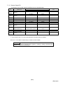
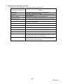
POINT
The ME96 must be handled after setting of the remote device station version. Set the remote device station
version with the “Setting Menu 2” of the ME96.
Use the following as a guideline in setting the remote device station version and set the version at ME96.
Mode select setting
Guideline for selection
Ver.1 remote device station
Select this when utilizing the conventional program, because of
(Ver.1 compatible slave station)
compatibility with ME96NSR.
Ver.2 remote device station
Select this when configuring a new system or the being newly
(Ver.2 compatible slave station)
added to the existing system in combination with the applicable
master module.
This programming manual is for ver.2 remote device station.
For use in the ver.1 remote device station (Ver.1 compatible slave station), refer to the following manual.
・Electronic Multi-Measuring Instrument Programing Manual (CC-Link)(For ver.1 remote device station)
..................................................................................................................................................... LEN080334
(3/n)
LEN130391
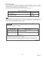
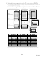
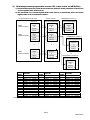
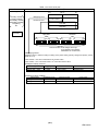
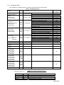
2. Specification
CC-Link specification is shown in Table 2.1 when ME96 is set the “Ver2.00” (ver.2 remote device station).
Table 2.1 CC-Link Specification (For Ver2.00)
Item
Specification
CC-Link station type
Number of occupied stations
Maximum number of stations
per master station
Transmission speed
Remote I/O (RX, RY)
Remote register (RWw, RWr)
Remote device station (ver.2 remote device station)
1 station (Expanded cyclic setting: Octuple)
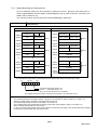
42 stations ( In case of connecting only remote device
station occupied by 1 station(Octplue).)
156kbps/625kbps/2.5Mbps/5Mbps/10Mbps
128 points each
32 points each
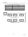
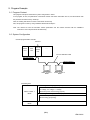
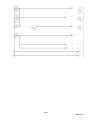
Master
station
ME96
ME96
ME96
Maximum number of connection is 42.
(In case of ME96 connection.)
ME96
ME96
ME96
System Configration (CC-Link)
(4/n)
LEN130391
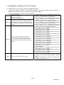
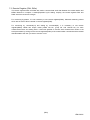
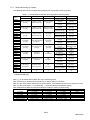
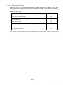
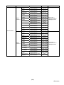
3. Configuration Conditions of CC-Link System
3.1 Remote net ver.2 mode, remote net addional mode
A total of 64 remote I/O stations, remote device stations, local stations, standby master stations, or
intelligent device stations can be connected to a single master station.
However, the following conditions must all be satisfied.
{(a+a2+a4+a8)
+(b+b2+b4+b8)×2
Condition 1
+(c+c2+c4+c8)×3
+(d+d2+d4+d8)×4}≦64
[{(a×32)+(a2×32)+(a4×64)+(a8×128)}
+{(b×64)+(b2×96)+(b4×192)+(b8×384)}
Condition 2 +{(c×96)+(c2×160)+(c4×320)+(c8×640)}
+{(d×128)+(d2×224)+(d4×448)+(d8×896)}]
≦8192
[{(a×4)+(a2×8)+(a4×16)+(a8×32)}
+{(b×8)+(b2×16)+(b4×32)+(b8×64)}
Condition 3 +{(c×12)+(c2×24)+(c4×48)+(c8×96)}
+{(d×16)+(d2×32)+(d4×64)+(d8×128)}]
≦2048
Condition 4 {(16×A) + (54×B) + (88×C)} ≦ 2304
a: The total number of ver.1 compatible slave stations that
occupy 1 station, and ver.2 compatible slave stations
that occupy 1 station which are set to “Single”.
b: The total number of ver.1 compatible slave stations that
occupy 2 stations, and ver.2 compatible slave stations
that occupy 2 stations which are set to “Single”.
c: The total number of ver.1 compatible slave stations that
occupy 3 stations, and ver.2 compatible slave stations
that occupy 3 stations which are set to “Single”.
d: The total number of ver.1 compatible slave stations that
occupy 4 stations, and ver.2 compatible slave stations
that occupy 4 stations which are set to “Single”.
a2: The number of ver.2 compatible stations that occupy 1
station which are set to “Double”.
b2: The number of ver.2 compatible stations that occupy 2
stations which are set to “Double”.
c2: The number of ver.2 compatible stations that occupy 3
stations which are set to “Double”.
d2: The number of ver.2 compatible stations that occupy 4
stations which are set to “Double”.
a4: The number of ver.2 compatible stations that occupy 1
station which are set to “Quadruple”.
b4: The number of ver.2 compatible stations that occupy 2
stations which are set to “Quadruple”.
c4: The number of ver.2 compatible stations that occupy 3
stations which are set to “Quadruple”.
d4: The number of ver.2 compatible stations that occupy 4
stations which are set to “Quadruple”.
a8: The number of ver.2 compatible stations that occupy 1
station which are set to “Octuple”.
(ME96 is applied)
b8: The number of ver.2 compatible stations that occupy 2
stations which are set to “Octuple”.
c8: The number of ver.2 compatible stations that occupy 3
stations which are set to “Octuple”.
d8: The number of ver.2 compatible stations that occupy 4
stations which are set to “Octuple”.
A: Number of remote I/O stations ≦64
B: Number of remote device stations (ME96 is applied)
≦42
C: Number of local stations, standby master stations and
intelligent device stations ≦26
(5/n)
LEN130391
ME96SSH-MB/SSR-MB
(6/n)
LEN130391
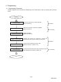
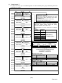
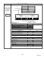
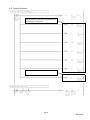
4. Programming
4.1 Programming Procedure
Create a program which executes the “Monitoring of the measurement valus” by following the procedure
below:
START
Parameter setting
Set the CPU parameter to start the data link.
(Refer to Section 5)
Selecting Commands
Select the command to transmit to the ME96.
(Refer to Section 0)
Initial Communication
Normal Communication
Required
In nesessary
Initialize the ME96.
(Refer to Section 6.2)
Transmit and receive the command to monitor the
measurement value. (Refer to Section 6.4,Section 0)
Required
Error Communication
Convert the data
Check the error status flag and error code.
(Rerer to Section 6.3, Section 7.2.6)
Convert the measurement data using the effective range
and multiplying factor. (Refer to Table 7.22)
In nesessary
End
(7/n)
LEN130391
5. Parameter Settings
5.1 Procedure from Parameter Settings to Data Link Startup
The following explains the procedure from setting the parameters to stating the data link.
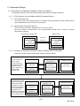
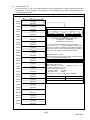
5.1.1
(1)
CPU Parameter Area and Master Module Parameter Memory
CPU Parameter Area
This area is used to set the basic values for controlling the programmable controller system and the
network parameters that control the CC-Link system.
(2)
Master Station Parameter Memory
This area stores the network parameters for the CC-Link system.
When the module is powered OFF or the programmable controller CPU is reset, the network
parameters are erased.
Programmable controller CPU
Parameter area
CC-Link system
network
parameter area
5.1.2
Master station
Parameter memory
Power ON
CPU reset
CC-Link system
network
parameter area
Procedure for Parameter Settings to Data Link Startup with GX Developer
Follow the procedure below for parameter settings to data link startup:
GX Developer
The GX Developer is
used to create
network parameters
and automatic refresh
parameters, which
are then written to the
programmable
controller CPU.
When the
programmable controller
system is powered ON
or the programmable
controller CPU is reset,
the network parameters
in the programmable
controller CPU are
transferred to the master
station and the data link
is automatically started.
Programmable controller CPU
Master station
CC-Link system
parameter area
Parameter memory
Network
parameters
Network
parameters
Network
parameters
Automatic refresh
parameters
Automatic refresh
parameters
GX Developer
Programmable controller CPU
CC-Link system
parameter area
Network
parameters
Network
parameters
Automatic refresh
parameters
Automatic refresh
parameters
Master station
Parameter memory
Network
parameters
(8/n)
LEN130391
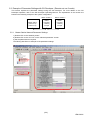
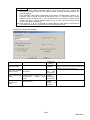
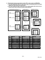
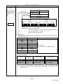
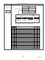
5.2 Example of Parameter Settings with GX Developer (Remote net ver.2 mode)
This section explains the parameter settings using the GX Developer. For more details on the GX
Developer operation, refer to the GX Developer Operating Manual. The explanations in this section are
based on the following example of the system configuration.
Master station
(X00 to X1F)
(Y00 to Y1F)
5.2.1
Station number 1
Station number 2
ME96
(occupies
1 station)
Octuple
ME96
(occupies
1 station)
Octuple
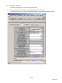
Master Station Network Parameter Settings
1) Double-click on the “Network param”.
2) Double-click on the “CC-Link” on the “Network parameter” screen.
3) Set the parameters as required.
The follwing describes an example of the parameter settings.
3)
1)
2)
(9/n)
LEN130391
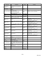
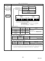
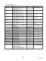
Setting Item
No.of boads in
module
Start I/O No
Operational settings
Type
Mode
All connect count
Remote input
(RX)
Remote output
(RY)
Remote register
(RWr)
Remote register
(RWw)
Special relay
(SB)
Special register
(SW)
Retry count
Automatic
reconnection station
count
Standby master
station No.
PLC down select
Scan mode setting
Delay information
setting
Station information
settings
Example for
settings
Description
Set the "No. of boards in module "
for which the network parameters
are to be
set.
Set the "Start I/O No." for the master
station.
Set the following:
・Parameter name
・Data link err station setting
・Case of CPU Stop setting
・Block data assurance per station
Set the station type.
Set the CC-Link mode.
Set the total number of connected
stations in the CC-Link system
including reserved stations.
Set the remote input (RX) refresh
device.
Set the remote output (RY) refresh
device.
Set the remote
refresh device.
register
0000
Refer to next
page.
Set the link special register (SW)
refresh device.
Set the number of retries for "Retry
count", when a communication error
occurs.
Set the number of modules that can
return to system operation by a
single link scan.
Set the station number for the
standby master station
Set the data link status for "PLC
down select", when a master station
programmable controller CPU error
occurs.
Set whether the link scan for the
sequence scan is synchronous or
asynchronous.
Set for the link scan delay time.
Even if the Parameter
name is not set, this will not affect the
operation of the CC-Link system
Master station
Remote net
(Ver.2 mode)
2 (modules)
X1000
Y1000
W0
Set the link special relay (SB)
refresh device.
Set the station data.
1
(RWr)
Set the remote register (RWw)
refresh device.
Remarks
W1000
SB0
SW0
Device name - Select from X, M, L, B, D,
W, R or ZR.
Device number - Within the range of the
device points that the CPU has.
Device name - Select from Y, M, L, B, T, C,
ST, D, W, R or ZR.
Device number - Within the range of the
device points that the CPU has.
Device name - Select from M, L, B, D, W,
R, or ZR.
Device number - Within the range of the
device points that the CPU has.
Device name - Select from M, L, B, T, C,
ST, D, W, R, or ZR.
Device number - Within the range of the
device points that the CPU has.
Device name - Select from M, L, B, D, W,
R, SB or ZR.
Device number - Within the range of the
device points that the CPU has.
Device name - Select from M, L, B, D, W,
R, SW or ZR.
Device number - Within the range of the
device points that the CPU has.
3
1
Blank
Blank: No standby master station specified.
Stop
Asynchronous
0
Refer to the
next page.
(10/n)
LEN130391
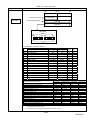
POINT
(1) For the automatic refresh parameter setting, set the start device only. Devices are
automatically assigned until the last station number including reserved stations and
occupied stations.
In the example of the system configuration in this section, the last station number is "2".
Therefore, total of remote I/O points is 256 points (128 x 2 = 256) and total of remote
registers points is 64 points (32 x 2 = 64). If refresh device of remote input (RX) is set to
"X1000" and that of remote registers (RWr) is set to "W0", the end devices will be
"X10FF" and "W3F" respectively.
(2) When setting X, Y, B, W, SB and SW as refresh devices, make setting so that they do
not overlap with the device numbers used on the other networks, etc.
《Example for Operational settings》
Setting Item
Example for
settings
Description
Set the Parameter name.
Parameter name
Data link disorder
satation setting
Case of CPU Stop
setting
Block data
assurance per
station
“SAMPLE”
Set the input status for the data link
error station.
Set
the
slave
station
refresh/compulsory clear setting at
programmable
controller
CPU
STOP.
Set the block guarantee of cyclic
data per station.
Remarks
Even if the Parameter
name is not set, this will not affect the
operation of the CC-Link system
Clear ("Hold
input
data"
not checked)
Refresh
("Clears
compulsorily "
not checked)
Disable
("Enable
setting"
not
checked)
(11/n)
LEN130391
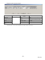
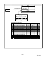
《Example for Station information settings》
Setting Item
Station type
Expanded cyclic setting
Description
Set the station data.
Example for
settings
Ver2. Remote device
station
Set the “ver2.00” in Setting Menu 7 of
ME96.
octuple
ME96 cannot use other than “octuple”.
Remarks
Number of occupied
Set the “Occupies 1 station” in case of
Occupies 1 station
stations *
the ME96.
Remote station points
128 points
Set the “128 points” in case of the ME96.
Reserved/invalid station
No setting
select
* "Number of exclusive stations" on the screen is described as "Number of occupied stations" in this manual.
"Exclusive station 1" on the screen is described as "Occupies 1 station" in this manual
(12/n)
LEN130391
6. Communication Between the Master Station and ME96
6.1 Communication Guideline
There are three communication statuses (Initial Communication, Normal Communication, Error
Communication) between the Master station and ME96.
In the normal communication, alarm status and digital input status of ME96 can be monitored using bit
data (remote input RX). Furthermore, the following can be performed by using remote input, remote
output and remote registers.
・ Monitoring by Pattern
・ Monitoring by Command(1H).
・ Setting by Command(2H).
For a monitoring by pattern, some measuring values can be monitored by selecting a bit of RY.
Measuring values which can be monitored have been already grouping in ME96 in advance. Please
select the necessary group in a bit of RY.
For a monitoring by command(1H), you can select any measurement items to be monitored. ME96 has
unique codes (called unit No., group No. and channel No.) for each measurement items. You can monitor
the selected measurement items by writing these codes to the remote registers.
For a setting by command(2H), you can set for ME96 settings.
* All measuring items can be monitored even when it is not displayed in ME96.
(13/n)
LEN130391
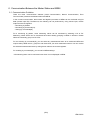
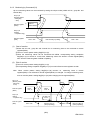
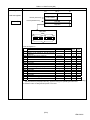
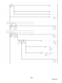
6.2 Initial Communication
Initial communication is performed at the beginning after the power supply is turned on or hardware is reset.
Refer to section 7.1 about the remote input RX and the remote output RY.
①
RX(n+7)8
(Initial data processing request flag)
③
④
②
RY(n+7)8
(Initial data setting completion flag)
③
RX(n+7)B
(Remote READY)
①After the power supply is turned on, or hardware is reset, the initial data processing request flag is turned on by
ME96.
②After the initial data processing request flag is turned on, turn on the initial data setting completion flag.
③After the initial data setting completion flag is turned on, the initial data processing request flag is turned
off and the remote READY is turned on.
④After the initial data processing request flag is turned off, turned off the initial data setting completion flag.
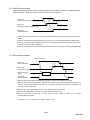
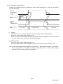
6.3 Error Communication
Error occurrence
①
RX(n+7)A
(Error status flag)
③
④
②
RY(n+7)A
(Error reset request flag)
②
⑤
Remote register
(RWr)
RX(n+7)B
Remote READY
Error code
①
①When an error occurs in ME96, error status flag is turned on and the remote READY is turned off.
②When the error status flag is turned on, read the error code from the remote register RWr. Eliminate the
cause of the error while referring to the red error code. When resuming communication with ME96, turn
on the error reset request flag.
③After the error reset request flag is turned on, the error status flag is turned off.
④After the error status flag is turned off, turn off the error reset request flag.
⑤After the error reset request flag is turned off, the remote READY is turned on and normal
communication is resumed.
Note: Refer to “7.2.6 About error occurrence” for error code.
(14/n)
LEN130391
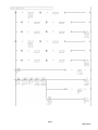
6.4 Normal Communication
After initial data processing is complete, allows the monitoring by pattern, monitoring by command(1H)
and setting by command(2H).
6.4.1
Monitoring by Pattern
Up to 16 mesuring values can be monitored by setting a bit of RY. Measuring values which can be
monitored have been already grouping in ME96 in advance. Therefore, select the necessary group in a
bit of RY. (Refer to section 7.1.2)
RY(n+1)m
(Monitor pattern
setting flag )
RX(n+1)m
(Setting
completion flag)
Remote register
(RWr)
(1)
③
①
②
Data = 00h
②
④
Data is always updating.
④
Data = 00h
Start of monitor
①Turns on monitor pattern setting flag(RY(n+1)m) which will be monitored.
②Corresponding setting completion flag(RX(n+1)m) is turned on when the measuring values can be
monitored at ME96. At this time, Measuring values are stored in remote registers(RWr) each time
the measuring data of ME96 is updating.
(2)
End of monitor
③Turns off monitor pattern setting flag(RY(n+1)m).
④Corresponding setting completion flag(RX(n+1)m) is turned off and remote registers are 00h.
Note: When turns on multiple monitor pattern setting flag(RY(n+1)*), setting completion flag is not turned
on. At this time, error status flag(RX(n+7)A) is turned on, and remote READY(RX(n+7)B) is turned
off.
(15/n)
LEN130391
6.4.2
Monitoring by Command(1H)
Up to 8 measuring values can be monitored by setting the unique codes (called unit No., group No. and
channel No.).
RY(n+1)0
(Monitor pattern
setting flag
= P00)
Remote register
(RWw)
①
Writes to
master station
RX(n+1)0
(Setting
completion flag)
⑤
③
Remote register
(RWr)
(1)
④
②
Data = 00h
③
Data is always updating.
⑤
Data = 00h
Start of monitor
①Writes the Unit No., group No and channel No. for measuring items to be monitored to remote
registers(RWw).
②Turns on monitor pattern setting flag(RY(n+1)0).
③When the measuring values can be monitored with ME96, corresponding setting completion
flag(RX(n+1)0) is turned on. At this time, Measuring values are stored in remote registers(RWr)
each time the measuring data of ME96 is updating.
(2)
End of monitor
④Turns off monitor pattern setting flag(RY(n+1)0).
⑤Corresponding setting completion flag(RX(n+1)m) is turned off and remote registers are 00h.
Note: When monitor pattern setting flag(RY(n+1)0) remains on, measuring items in remote
registers(RWr) is not reflected if remote registers(RWw) is changed. To change measuring items,
turns on monitor pattern setting flag(RY(n+1)0) after changing remote registers(RWw).
RY(n+1)0
(Monitor pattern
setting flag
=P00)
Remote register
(RWw)
Writes
code “A”
RX(n+1)0
(Setting
completion flag)
Remote register
(RWr)
Writes
code “B”
Not
reflected.
Data = 00h
Mesuring data “A”
(Always updating)
Data = 00h
Mesuring data “B”
(Always updating)
(16/n)
LEN130391
6.4.3
Setting by Command(2H)
A setting item of ME96 can be set by setting the unique codes (called unit No., group No. and channel
No.) and setting data.
RY(n+1)0
(Monitor pattern
setting flag
=P00)
Remote register
(RWw)
①
Writes to
master station
RX(n+1)0
(Setting
completion frag)
Remote register
(RWr)
(1)
④
②
⑤
③
Data = 00h
③
Response data
Data = 00h
⑤
Setting
①Writes the Unit No., group No, channel No. and setting data to remote registers(RWw).
②Turns on monitor pattern setting flag(RY(n+1)0).
③After checking for data at ME96, corresponding setting completion flag(RX(n+1)0) is turned on. At
this time, response data are stored in remote registers(RWr).
(2) End of setting
④Turns off monitor pattern setting flag(RY(n+1)0).
⑤Corresponding setting completion flag(RX(n+1)m) is turned off and remote registers are 00h.
Note: When monitor pattern setting flag(RY(n+1)0) remains on, setting data of ME96 is not reflected if
remote registers(RWw) is changed. To change setting data, turns on monitor pattern setting
flag(RY(n+1)0) after writing remote registers(RWw).
(17/n)
LEN130391
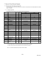
7. Remote I/O and Remote Register
7.1 Remote Input RX, Remote Output RY
The remote input RX and remote output RY are used to communicate for bit data between the master
station and ME96.
7.1.1
Remote input RX
The allocation of the remote input RX of ME96 is shown in the table below.
Device
No.
Signal name
Description
ME96
SSR
ME96
SSH
OFF(0)
ON(1)
-
Not
e
RXn0
Digital Input 1 (DI1)
○
○
-
RXn1
Digital Input 2 (DI2)
○
○
-
-
RXn2
Digital Input 3 (DI3)
○
○
Non-Alarm state
Alarm state
RXn3
Digital Input 4 (DI4)
○
○
Non-Alarm state
Alarm state
RXn4
Reserved
-
-
OFF
ON
RXn5
Alarm (Total)
○
○
Non-Alarm state
Alarm state
RXn6
○
○
OFF
ON
*2
-
○
OFF
ON
*2
RXn8
Alarm of Current Demand
Alarm of
Active power Demand
Alarm of Voltage
○
○
Non-Alarm state
Alarm state
*2
RXn9
Alarm of Current
○
○
Non-Alarm state
Alarm state
*2
RXnA
Alarm of Active power
○
○
Non-Alarm state
Alarm state
*2
RXn7
RXnB
Alarm of Reactive power
○
○
Non-Alarm state
Alarm state
*2
RXnC
Alarm of Frequency
○
○
Non-Alarm state
Alarm state
*2
RXnD
Alarm of Power factor
○
○
Non-Alarm state
Alarm state
*2
RXnE
Alarm of T.H.D (Voltage)
○
○
Non-Alarm state
Alarm state
*2
RXnF
Alarm of harmonic current
*2
○
○
Non-Alarm state
Alarm state
RX(n+1)0
RX(n+1)1
to
RX(n+1)7
RX(n+1)8
Setting completion flag P00
○
○
Not receiving
Receiving
Reserved
-
-
-
-
Setting completion flag P08
○
○
Not receiving
Receiving
RX(n+1)9
Setting completion flag P09
○
○
Not receiving
Receiving
RX(n+1)A
Setting completion flag P10
○
○
Not receiving
Receiving
RX(n+1)B
Setting completion flag P11
○
○
Not receiving
Receiving
RX(n+1)C
RX(n+1)D
to
RX(n+7)7
Setting completion flag P12
○
○
Not receiving
Receiving
Reserved
-
-
-
-
Power OFF, remote READY
ON, or error status flag ON
-
No error occurrence
Monitoring or setting are not
possible
Power supply is turned ON or
hardware reset
-
Error occurrence
○
○
RX(n+7)9
RX(n+7)A
Initial data processing
request flag
Reserved
Error status flag
-
○
-
○
RX(n+7)B
Remote READY
○
○
RX(n+7)C
to
RX(n+7)F
Reserved
-
-
RX(n+7)8
*1
*1
Normally communication status *1
-
-
*1: For the details, refer to “6.Communication Between the Master Station and ME96”
*2: “ON(1)” shows the state where the upper limit or the lower limit is exceeded.
Note: “n” in the table is determined by the station number of ME96.
(18/n)
LEN130391
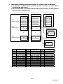
(1)
1)
Relationships between programmable controller CPU, master module and ME96(RX)
1) The input status of ME96 is stored automatically (for each link scan) in the master station's
"remote input RX" buffer memory.
2) The input status stored in the "remote input RX" buffer memory is stored in the CPU device set
with the automatic refresh parameters.
Programmable controller CPU
ME96
(Station number1)
ME96
(Station number2)
Master module
ME96(Station number 1)
Device X
Remote input(RX)
Remote input(RX)
X1000 to X100F
X1010 to X101F
X1020 to X102F
X1030 to X103F
X1040 to X104F
X1050 to X105F
X1060 to X106F
X1070 to X107F
X1000 to X100F
to
X10F0 to X10FF
RX00 to RX0F
RX10 to RX1F
RX20 to RX2F
RX30 to RX3F
RX40 to RX4F
RX50 to RX5F
RX60 to RX6F
RX70 to RX7F
RX80 to RX8F
RX00 to RX0F
RX10 to RX1F
RX20 to RX2F
RX30 to RX3F
RX40 to RX4F
RX50 to RX5F
RX60 to RX6F
RX70 to RX7F
2)
2)
1)
1)
ME96(Station number 2)
RXF0 to RXFF
Remote input(RX)
to
ME96
X2480 to X248F
(Station number42)
to
X24F0 to X24FF
RX00 to RX0F
to
RX70 to RX7F
to
2)
RX1480 to RX148F
to
RX14F0 to RX14FF
1)
to
ME96(Station number 42)
Remote input(RX)
RX00 to RX0F
to
RX70 to RX7F
Station
Station
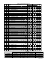
Station
Device No.
Device No.
Device No.
number
number
number
1
X1000 to X107F 15
X1700 to X177F 29
X1E00 to X1E7F
2
X1080 to X10FF 16
X1780 to X17FF 30
X1E80 to X1EFF
3
X1100 to X117F 17
X1800 to X187F 31
X1F00 to X1F7F
4
X1180 to X11FF 18
X1880 to X18FF 32
X1F80 to X1FFF
5
X1200 to X127F 19
X1900 to X197F 33
X2000 to X207F
6
X1280 to X12FF 20
X1980 to X19FF 34
X2080 to X20FF
7
X1300 to X137F 21
X1A00 to X1A7F 35
X2100 to X217F
8
X1380 to X13FF 22
X1A80 to X1AFF 36
X2180 to X21FF
9
X1400 to X147F 23
X1B00 to X1B7F 37
X2200 to X227F
10
X1480 to X14FF 24
X1B80 to X1BFF 38
X2280 to X22FF
11
X1500 to X157F 25
X1C00 to X1C7F 39
X2300 to X237F
12
X1580 to X15FF 26
X1C80 to X1CFF 40
X2380 to X23FF
13
X1600 to X167F 27
X1D00 to X1D7F 41
X2400 to X247F
14
X1680 to X16FF 28
X1D80 to X1DFF 42
X2480 to X24FF
Device No. is determined to “X1000 to X24FF” if refresh device of remote input (RX) is set to “X1000”.
(19/n)
LEN130391
7.1.2
Remote Output RY
The allocation of the remote output RY of ME96 is shown in the table below.
Device
No.
RYn0
to
RYnF
RY(n+1)0
RY(n+1)1
to
RY(n+1)7
RY(n+1)8
RY(n+1)9
RY(n+1)A
Signal name
Description
ON(1)→OFF(0)
OFF(0)→ON(1)
-
-
Not setting
Setting
-
-
Monitor pattern setting flag P08
Not setting
Setting
Monitor pattern setting flag P09
Not setting
Setting
Monitor pattern setting flag P10
Not setting
Setting
Reserved
Monitor pattern setting flag P00
Reserved
RY(n+1)B
Monitor pattern setting flag P11
Not setting
Setting
RY(n+1)C
RY(n+1)D
to
RY(n+7)7
Monitor pattern setting flag P12
Not setting
Setting
Reserved
-
-
Initial data
Cancel normal
communication request
Normal communication
request
RY(n+7)8
setting completion flag
RY(n+7)9
Unusable
RY(n+7)A
RY(n+7)B
to
RY(n+7)F
Error reset request flag
Unusable
-
-
Cancel error reset request
Error reset request
-
-
Note
*1
*1
*1: For the details, refet to “6.Communication Between the Master Station and ME96”
Note: The “n” in the table is determined by the station number of ME96.
Point
Do not read or write to reserved remote registers. If reading or writing is performed, the
functions of ME96 are not guaranteed.
(20/n)
LEN130391
(1)
1)
Relationships between programmable controller CPU, master module and ME96(RY)
1) The on/off data of the CPU device set with the automatic refresh parameters is stored in the
"remote output RY" buffer memory.
2) Remote output RY is automatically set to on/off (for each link scan) according to the output status
stored in the "remote output RY" buffer memory.
Programmable controller CPU
ME96
(Station number1)
ME96
(Station number2)
Master module
ME96(Station number 1)
Device Y
Remote output(RY)
Remote output(RY)
Y1000 to Y100F
Y1010 to Y101F
Y1020 to Y102F
Y1030 to Y103F
Y1040 to Y104F
Y1050 to Y105F
Y1060 to Y106F
Y1070 to Y107F
Y1000 to Y100F
to
Y10F0 to Y10FF
RY00 to RY0F
RY10 to RY1F
RY20 to RY2F
RY30 to RY3F
RY40 to RY4F
RY50 to RY5F
RY60 to RY6F
RY70 to RY7F
RY80 to RY8F
RY00 to RY0F
RY10 to RY1F
RY20 to RY2F
RY30 to RY3F
RY40 to RY4F
RY50 to RY5F
RY60 to RY6F
RY70 to RY7F
1)
1)
2)
2)
ME96(Station number 2)
RYF0 to RYFF
Remote output(RY)
to
RY00 to RY0F
to
RY70 to RY7F
to
ME96
Y2480 to Y248F
(Station number42)
to
Y24F0 to Y24FF
1)
RY1480 to RY148F
to
RY14F0 to RY14FF
2)
to
ME96(Station number 42)
Remote output(RY)
RY00 to RY0F
to
RY70 to RY7F
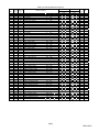
Station
number
1
2
3
4
5
6
7
8
9
10
11
12
13
14
Device No.
Y1000
Y1080
Y1100
Y1180
Y1200
Y1280
Y1300
Y1380
Y1400
Y1480
Y1500
Y1580
Y1600
Y1680
to
to
to
to
to
to
to
to
to
to
to
to
to
to
Y107F
Y10FF
Y117F
Y11FF
Y127F
Y12FF
Y137F
Y13FF
Y147F
Y14FF
Y157F
Y15FF
Y167F
Y16FF
Station
number
15
16
17
18
19
20
21
22
23
24
25
26
27
28
Device No.
Y1700
Y1780
Y1800
Y1880
Y1900
Y1980
Y1A00
Y1A80
Y1B00
Y1B80
Y1C00
Y1C80
Y1D00
Y1D80
to
to
to
to
to
to
to
to
to
to
to
to
to
to
Y177F
Y17FF
Y187F
Y18FF
Y197F
Y19FF
Y1A7F
Y1AFF
Y1B7F
Y1BFF
Y1C7F
Y1CFF
Y1D7F
Y1DFF
Station
number
29
30
31
32
33
34
35
36
37
38
39
40
41
42
Device No.
Y1E00
Y1E80
Y1F00
Y1F80
Y2000
Y2080
Y2100
Y2180
Y2200
Y2280
Y2300
Y2380
Y2400
Y2480
to
to
to
to
to
to
to
to
to
to
to
to
to
to
Y1E7F
Y1EFF
Y1F7F
Y1FFF
Y207F
Y20FF
Y217F
Y21FF
Y227F
Y22FF
Y237F
Y23FF
Y247F
Y24FF
Device No. is determined to “Y1000 to Y24FF” if refresh device of remote output (RY) is set to “Y1000”.
(21/n)
LEN130391
7.2 Remote Register (RWr, RWw)
The remote registers RWr and RWw are used to communicate word data between the master station and
ME96. Because it occupiers 1 station(Expanded cyclic setting: octuple), the remote registers RWr and
RWw each have 32 words in length.
For monitoring by pattern, it is not necessary to use remote registers(RWw). Selected measuring values
which are set a bit of RY are stored in remote registers(RWr).
For monitoring by command(1H) and setting by command(2H), it is necessary to use remote
registers(RWw). ME96 has unique codes (called unit No., group No. and channel No.) for each
measurement items and setting items. It becomes possible to monitor each measurement values or set
each parameters by writing into the remote registers(RWw) of the master station command and the related
data allocated to the item you want to monitor or set.
(22/n)
LEN130391
(1)
1)
Relationships between programmable controller CPU, master module and ME96(RWr)
1) The remote registers RWr data of a remote device station is automatically stored in the "remote
registers Rwr" buffer memory of the master station.
2) The remote registers RWr data of ME96 stored in the "remote registers RWr" buffer memory is
stored in the CPU device set with the automatic refresh parameters.
Programmable controller CPU
ME96
(Station number1)
ME96
(Station number2)
Master module
Device No.
Remote register(RWr)
Remote register(RWr)
W0000
W0001
to
W001E
W001F
W0020
W0021
to
W003E
W003F
RWr00
RWr01
to
RWr1E
RWr1F
RWr20
RWr21
to
RWr3E
RWr3F
RWr00
RWr01
to
RWr1E
RWr1F
2)
2)
to
ME96
(Station number42)
ME96(Station number 1)
W0520
W0521
to
W053E
W053F
1)
1)
ME96(Station number 2)
Remote register(RWr)
RWr00
RWr01
to
RWr1E
RWr1F
to
RWr520
RWr521
to
RWr53E
RWr53F
2)
1)
to
ME96(Station number 42)
Remote register(RWr)
RWr00
RWr01
to
RWr1E
RWr1F
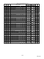
Station
Station
Station
Device No.
Device No.
Device No.
number
number
number
1
W0000 to W001F 15
W01C0 to W01DF 29
W0380 to
2
W0020 to W003F 16
W01E0 to W01FF 30
W03A0 to
3
W0040 to W005F 17
W0200 to W021F 31
W03C0 to
4
W0060 to W007F 18
W0220 to W023F 32
W03E0 to
5
W0080 to W009F 19
W0240 to W025F 33
W0400 to
6
W00A0 to W00BF 20
W0260 to W027F 34
W0420 to
7
W00C0 to W00DF 21
W0280 to W029F 35
W0440 to
8
W00E0 to W00FF 22
W02A0 to W02BF 36
W0460 to
9
W0100 to W011F 23
W02C0 to W02DF 37
W0480 to
10
W0120 to W013F 24
W02E0 to W02FF 38
W04A0 to
11
W0140 to W015F 25
W0300 to W031F 39
W04C0 to
12
W0160 to W017F 26
W0320 to W033F 40
W04E0 to
13
W0180 to W019F 27
W0340 to W035F 41
W0500 to
14
W01A0 to W01BF 28
W0360 to W037F 42
W0520 to
Device No. is determined to “W0000 to W053F” if refresh device of remote registers (RWr) is
W039F
W03BF
W03DF
W03FF
W041F
W043F
W045F
W047F
W049F
W04BF
W04DF
W04FF
W051F
W053F
set to “W0”.
(23/n)
LEN130391
(2)
2)
Relationships between programmable controller CPU, master module and ME96(RWw)
1) The transmission data of the CPU device set with the automatic refresh parameters is stored in the
"remote registers RWw" buffer memory.
2) The data stored in the "remote registers RWw" buffer memory is automatically sent to the remote
registers RWw of each remote device station.
Programmable controller CPU
ME96
(Station number1)
ME96
(Station number2)
Master module
Device No.
Remote register(RWw)
Remote register(RWw)
W1000
W1001
to
W101E
W101F
W1020
W1021
to
W103E
W103F
RWw00
RWw01
to
RWw1E
RWw1F
RWw20
RWw21
to
RWw3E
RWw3F
RWw00
RWw01
to
RWw1E
RWw1F
1)
1)
to
ME96
(Station number42)
ME96(Station number 1)
W1520
W1521
to
W153E
W153F
2)
2)
ME96(Station number 2)
Remote register(RWw)
RWw00
RWw01
to
RWw1E
RWw1F
to
RWw520
RWw521
to
RWw53E
RWw53F
1)
2)
to
ME96(Station number 42)
Remote register(RWw)
RWw00
RWw01
to
RWw1E
RWw1F
Station
Station
Device No.
Device No.
number
number
1
W1000 to W101F 15
W11C0 to
2
W1020 to W103F 16
W11E0 to
3
W1040 to W105F 17
W1200 to
4
W1060 to W107F 18
W1220 to
5
W1080 to W109F 19
W1240 to
6
W10A0 to W10BF 20
W1260 to
7
W10C0 to W10DF 21
W1280 to
8
W10E0 to W10FF 22
W12A0 to
9
W1100 to W111F 23
W12C0 to
10
W1120 to W113F 24
W12E0 to
11
W1140 to W115F 25
W1300 to
12
W1160 to W117F 26
W1320 to
13
W1180 to W119F 27
W1340 to
14
W11A0 to W11BF 28
W1360 to
Device No. is determined to “W1000 to W153F” if refresh device
W11DF
W11FF
W121F
W123F
W125F
W127F
W129F
W12BF
W12DF
W12FF
W131F
W133F
W135F
W137F
Station
number
29
30
31
32
33
34
35
36
37
38
39
40
41
42
Device No.
W1380
W13A0
W13C0
W13E0
W1400
W1420
W1440
W1460
W1480
W14A0
W14C0
W14E0
W1500
W1520
to
to
to
to
to
to
to
to
to
to
to
to
to
to
W139F
W13BF
W13DF
W13FF
W141F
W143F
W145F
W147F
W149F
W14BF
W14DF
W14FF
W151F
W153F
of remote registers (RWw) is set to “W1000”.
(24/n)
LEN130391
7.2.1
When Monitoring by Pattern
The following table shows correspondence between RY and grouped measuring items.
Table 7.1 Correspondence between RY and grouped measuring items
device.
RWr00
RWr01
RWr02
RWr03
RWr04
RWr05
RWr06
RWr07
RWr08
RWr09
RWr0A
RWr0B
RWr0C
RWr0D
RWr0E
RWr0F
RWr10
RWr11
RWr12
RWr13
RWr14
RWr15
RWr16
RWr17
RWr18
RWr19
RWr1A
RWr1B
RWr1C
RWr1D
RWr1E
RWr1F
Group
format
P08
RY(n+1)8
P09
RY(n+1)9
P10
RY(n+1)A
Phase 1 current
(Inst.)[A]
Phase 1 current
demand (Inst.)[A]
Phase N current
(Inst.)[A]
Phase 2 current
(Inst.)[A]
Phase 2 current
demand (Inst.)[A]
Phase N current
demand (Inst.)[A]
Phase 3 current
(Inst.)[A]
Phase 3 current
demand (Inst.)[A]
1-N Voltage
(Inst.)[V]
1-2 Voltage
(Inst.)[V]
Total rolling demand
(Inst.)[kW] *1
2-N Voltage
(Inst.)[V]
2-3 Voltage
(Inst.)[V]
Total power factor
(Inst.)[%]
3-N Voltage
(Inst.)[V]
3-1 Voltage
(Inst.)[V]
Frequency
(Inst.)[Hz]
00h
(No items)
Total active power Total reactive power
(Inst.)[kW]
(Inst.)[kvar]
00h
(No items)
Active energy
import[kWh]
Reactive energy
import lag [kvarh]
00h
(No items)
①
①
①
P11
RY(n+1)B
P12
RY(n+1)C
Phase 1 current
(Inst.)[A]
Phase N current
(Inst.)[A]
Phase 2 current
(Inst.)[A]
Phase N current
demand (Inst.)[A]
Phase 3 current
(Inst.)[A]
1-N Voltage
(Inst.)[V]
Phase 1 current
demand (Inst.)[A]
2-N Voltage
(Inst.)[V]
Phase 2 current
demand (Inst.)[A]
3-N Voltage
(Inst.)[V]
Phase 3 current
demand (Inst.)[A]
Average current
(Inst.)[A]
1-2 Voltage
(Inst.)[V]
Avrage current
demand (Inst.)[A]
2-3 Voltage
(Inst.)[V]
Average L-L
voltage (Inst.)[V]
3-1 Voltage
(Inst.)[V]
Average L-N
voltage (Inst.)[V]
Total active power
(Inst.)[kW]
00h
(No items)
Total rolling demand
(Inst.)[kW] *1
00h
(No items)
Total reactive power
(Inst.)[kvar]
00h
(No items)
Total power factor
(Inst.)[%]
00h
(No items)
Frequency
(Inst.)[Hz]
00h
(No items)
Active energy
import[kWh]
00h
(No items)
Reactive energy
import lag [kvarh]
00h
(No items)
②
②
Inst.: Instantaneous value
*1: ME96SSH-MB Only.
Note: “[ ]” in the above table indicate the unit of measuring items.
Note: P10 and P12 can be used for 3P4W only. In others, the error will occur.
Note: For the active power (demand) and reactive power, ±1638.3MW(Mvar) becomes the upper(lower) value.
Note: For the power factor, “+” is showed lag, “-“ is showed lead as with ME96’s display.
Note: Measurement data correspond as follows according to setting of phase wiring.
Name of channel
1-2 voltage
2-3 voltage
3-1 voltage
Phase 1 current
Phase 2 current
Phase 3 current
3P3W
1-2 voltage
2-3 voltage
3-1 voltage
Phase 1 current
Phase 2 current
Phase 3 current
Phase wiring
1P3W(1N3)
1P3W(1N2)
1-N voltage
1-N voltage
3-N voltage
2-N voltage
1-3 voltage
1-3 voltage
Phase 1 current
Phase 1 current
Phase N current
Phase N current
Phase 3 current
Phase 2 current
1P2W
Voltage
Current
-
(25/n)
LEN130391
(1)
Group format ①
For group format ①, Up to 8 measuring items can be monitored per a group. Measuring items are
expressed in 4 words.
Group format ①
b15
b8
b7
b0
RWr00
Channel No.
Group No.
RWr01
Index number
00h
RWr02
Low data
RWr03
High data
<Channel No., Group No.>
ME96 returns fixed data determined for each
measuring items. (About fixed data, refer to Table
7.2 to Table 7.12)
(Example:When selected phase 1 current (Inst),
channel No.is 21h, group No. is 01h.)
RWr04
Channel No.
Group No.
RWr05
Index number
00h
<Multiplying factor>
Multiplying factor is fixed for each items according to
phase wire system, primary voltage and primary
current.(For details, refer to Table 7.22)
■Correspondence of index number and multiplying
factor.
Index
Multiplying
Remarks
number
factor
2
02H
×10
01H
×10
Actual value =
00H
×1
Numerical value
FFH
×10-1
× Multiplying factor
FEH
×10-2
FDH
×10-3
FCH
×10-4
RWr06
Low data
RWr07
High data
RWr08
Channel No.
Group No.
RWr09
Index number
00h
RWr0A
Low data
RWr0B
High data
RWr0C
Channel No.
Group No.
RWr0D
Index number
00h
RWr0E
Low data
RWr0F
High data
<Numerical value>
RWr10
Channel No.
Group No.
RWr11
Index number
00h
RWr12
Low data
RWr13
High data
RWr14
Channel No.
Group No.
RWr15
Index number
00h
RWr16
Low data
RWr17
High data
RWr18
Channel No.
Group No.
RWr19
Index number
00h
RWr1A
Low data
RWr1B
High data
RWr1C
Channel No.
Group No.
RWr1D
Index number
00h
RWr1E
Low data
RWr1F
High data
High data
b31
b24 b23
Low data
b16 b15
b8
b7
b0
Numerical value: 32-bit integer with a sign
-2147483648~2147483647
(80000000H~7FFFFFFFH)
■Example: Active power
Index
Data
number
(Numerical value)
FFH
000000FFH ⇒ 255
00H
FFFFFF01H ⇒ -255
■Example: power factor
Index
Data
number
(Numerical value)
FFH
000003E3H ⇒ 995
FFH
FFFFFC1DH⇒ -995
Actual value
255×10-1=25.5[kW]
-255×1=-255[kW]
Actual value
995×10-1=99.5[%]
-995×10-1=-99.5[%]
(26/n)
LEN130391
(2)
Group format ②
For group format ②, Up to 16 measuring items can be monitored per a group. Measuring items are
expressed in 2 words. However, it is necessary to be multiplied by using Table 7.22 because there is
no multiplying factor data .
Group format ②
b15
b8
b7
RWr00
Low data
RWr01
High data
RWr02
Low data
RWr03
High data
RWr04
Low data
RWr05
High data
RWr06
Low data
RWr07
High data
RWr08
Low data
RWr09
High data
RWr0A
Low data
RWr0B
High data
RWr0C
Low data
RWr0D
High data
RWr0E
Low data
RWr0F
High data
RWr10
Low data
RWr11
High data
RWr12
Low data
RWr13
High data
RWr14
Low data
RWr15
High data
RWr16
Low data
RWr17
High data
RWr18
Low data
RWr19
High data
RWr1A
Low data
RWr1B
High data
RWr1C
Low data
RWr1D
High data
RWr1E
Low data
RWr1F
High data
b0
<Numerical value>
High data
b31
b24 b23
Low data
b16 b15
b8
b7
b0
Numerical value: 32-bit integer with a sign
-2147483648~2147483647
(80000000H~7FFFFFFFH)
Format of numerical value is same to group format ①.
This format is not contain multiplying factor data.
Therefore, Confirm the multiplying factor fixed according to
phase wire system, primary voltage and primary current by
Table 7.22, and multiply it using sequence program.
■Example: Phase 1 current
When setting of primary current is 200A, multiplying factor
-1
is ×10 according to section Table 7.22.
Data(Numerical value)
Actual value
000000FFH ⇒ 255
255×10-1=25.5[A]
■Example: Active power
When settings are follows, multiplying factor is ×10
according to section Table 7.22.
・Phase wire system: 3P4W
・Primary voltage:
254/440V
・Primary current:
2000A
→Total load = 3 × 254 × 2000 / 1000 = 1524[kW]
Data(Numerical value)
0000FFFFH ⇒ 65535
Actual value
65535×10=655350[kWh]
(27/n)
LEN130391
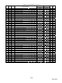
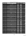
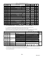
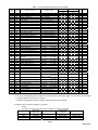
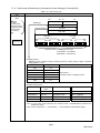
7.2.2
When Monitoring by Command(1H)
Up to 8 measuring values can be monitored by setting the unit No., group No. and channel No. to
remote registers(RWw). Monitor pattern setting flag(RX(n+1)0) is used to send the command. (For
details, refer to section 6.4.2)
The command can be sent only when the remote READY(RX(n+7)B) is ON.
1H
Data Monitor
Remote register RWw(Programmable controller→ME96)
b15
b8
b7
Unit
No.
Remote register RWw(ME96→Programmable controller)
b15
b0
b7
Channel No.
Group No.
RWr01
Index number
(Error code)
Group No.
RWw01
00H
Channel No.
RWw02
00H
00H
RWw03
00H
RWw04
Group No.
RWw05
00H
Channel No.
RWw06
00H
00H
RWr06
Low data
RWw07
00H
00H
RWr07
High data
to
to
Item 1
00H
Unit
No.
1H
Item 2
to
Unit
No.
RWw1C
Group No.
1H
RWw1D
00H
Channel No.
RWw1E
00H
00H
RWw1F
00H
00H
Item 8
b0
RWr00
RWw00
to
1H
b8
RWr02
Low data
RWr03
High data
RWr04
Channel No.
Group No.
RWr05
Index number
(Error code)
RWr1C
Channel No.
Group No.
RWr1D
Index number
(Error code)
RWr1E
Low data
RWr1F
High data
Item 1
Item 2
Item 8
* At normal communication, Error code is 00h.
About the other error code, refer to Table 7.23.
* It is described as 8 bits data by combining the unit No. (high 4 bits) and the command (low 4 bits)
b7
b4 b3
b0
Command: Data range is 0H to 7H
Unit No.: Data range is 0H to 7H
(0H or 1H is used for the unit No. of ME96.)
For example, When the unit No. is 0H and the command is 1H, it becomes “01H”.
・
・
・
・
・
・
・
ME96 can monitor the value of measurement items which are not displayed.
The measurement items are assigned Unit No., Group No. and Channel No. (Refer to Table 7.2 to Table 7.12)
Store the unused space to 00H when monitoring items are under 8.
The details of data format are shown in the Table 7.14 to Table 7.21
The monitering items are changed with the setting of phase wire system.(Refer to Table 7.2 to Table 7.12)
When conbined command(2H), an error occers.
In case of monitoring the present value and its maximum continuously according to the renewal data timing of ME96,
the maximum may be smaller than the present value.
(28/n)
LEN130391
Table 7.2 Group Channel List (1/11)
Unit
No.
0
0
0
0
0
0
0
0
0
0
0
0
0
0
0
0
0
0
0
0
0
0
0
0
0
0
0
0
0
0
0
0
0
0
0
0
0
0
0
0
0
0
0
0
0
0
0
0
0
0
0
0
0
0
0
0
Group Channel
(h)
(h)
F0
E0
E0
E0
E0
E0
E0
E0
E0
E0
E0
02
08
08
01
01
01
01
01
01
01
01
01
01
01
01
01
01
01
02
02
02
02
02
02
02
02
02
02
02
02
02
02
02
05
05
05
05
05
05
05
05
05
05
05
05
02
11
12
1B
1C
13
1D
1E
18
19
1A
E0
E4
E5
01
21
41
61
81
02
22
42
62
82
05
25
45
65
85
01
21
41
61
81
02
22
42
62
82
05
25
45
65
85
01
21
41
61
02
22
42
62
05
25
45
65
ME96SSH-MB
Name of Cannel
Model code
Primary current
Primary voltage(L-L)
Primary voltage(L-N)
Secondary voltage(L-N)
Phase & Wiring
Frequency
Secondary current
Alarm items
Byte monitor
Attribute monitor
Time constant for current demand
Interval time constant
Subinterval time constant
Average current
Phase 1 current
Phase 2 current
Phase 3 current
Phase N current
Average current
Phase 1 current
Phase 2 current
Phase 3 current
Phase N current
Average current
Phase 1 current
Phase 2 current
Phase 3 current
Phase N current
Average current demand
Phase 1 current demand
Phase 2 current demand
Phase 3 current demand
Phase N current demand
Average current demand
Phase 1 current demand
Phase 2 current demand
Phase 3 current demand
Phase N current demand
Average current demand
Phase 1 current demand
Phase 2 current demand
Phase 3 current demand
Phase N current demand
Average L-L voltage
1-2 voltage
2-3 voltage
3-1 voltage
Average L-L voltage
1-2 voltage
2-3 voltage
3-1 voltage
Average L-L voltage
1-2 voltage
2-3 voltage
3-1 voltage
ME96SSR-MB Data
Note
type
3P3W
3P3W
3P4W
1P2W 3P4W
1P2W
1P3W
1P3W
sec.
min.
min.
A
A
A
A
A
A
A
A
A
A
A
A
A
A
A
A
A
A
A
A
A
A
A
A
A
A
A
A
A
A
V
V
V
V
V
V
V
V
V
V
V
V
Inst.
Inst.
Inst.
Inst.
Inst.
max.
max.
max.
max.
max.
min.
min.
min.
min.
min.
Inst.
Inst.
Inst.
Inst.
Inst.
max.
max.
max.
max.
max.
min.
min.
min.
min.
min.
Inst.
Inst.
Inst.
Inst.
max.
max.
max.
max.
min.
min.
min.
min.
○
○
○
○
○
○
○
○
○
○
○
○
○
○
○
○
○
○
○
○
○
○
○
○
○
○
○
○
○
○
○
○
○
○
○
○
○
○
○
○
○
○
○
○
○
○
○
○
○
○
○
○
○
○
○
○
○
○
○
○
○
○
○
○
○
○
○
○
○
○
○
○
○
○
○
○
○
○
○
○
○
○
○
○
○
○
○
○
○
○
○
○
○
○
○
○
○
○
○
○
○
○
○
○
○
○
○
○
○
○
○
○
○
○
○
○
○
○
○
○
○
○
○
○
○
○
○
-
○
○
○
○
○
○
○
○
○
○
○
○
○
○
○
○
○
○
○
○
○
○
○
○
○
○
○
○
○
○
○
○
○
○
○
○
○
○
○
○
○
○
○
○
○
○
○
○
○
○
○
○
○
○
○
○
○
○
○
○
○
○
○
○
○
○
○
○
○
○
○
○
○
○
○
○
○
○
○
○
○
○
○
○
○
○
○
○
○
○
○
○
○
○
○
○
○
○
○
○
○
○
○
○
○
○
○
○
○
○
○
○
○
○
○
○
○
○
○
○
○
-
⑥
⑤
⑤
⑤
⑤
⑥
⑤
⑤
⑦
⑥
⑥
⑥
⑥
⑥
①
①
①
①
①
①
①
①
①
①
①
①
①
①
①
①
①
①
①
①
①
①
①
①
①
①
①
①
①
①
①
①
①
①
①
①
①
①
①
①
①
①
*2,*3
Note: Measurement data correspond as follows according to setting of phase wiring. (Maximum / Minimum data and harmonic data are same.)
Phase wiring
Name of channel
3P3W
1P3W(1N3)
1P3W(1N2)
1P2W
1-2 voltage
1-2 voltage
1-N voltage
1-N voltage
Voltage
2-3 voltage
2-3 voltage
3-N voltage
2-N voltage
3-1 voltage
3-1 voltage
1-3 voltage
1-3 voltage
Phase 1 current
Phase 1 current
Phase 1 current
Phase 1 current
Current
Phase 2 current
Phase 2 current
Phase N current
Phase N current
Phase 3 current
Phase 3 current
Phase 3 current
Phase 2 current
-
(29/n)
LEN130391
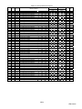
Table 7.3 Group Channel List (2/11)
Unit
No.
0
0
0
0
0
0
0
0
0
0
0
0
0
0
0
0
0
0
0
0
0
0
0
0
0
0
0
0
0
0
0
0
0
0
0
0
0
0
1
1
1
1
1
1
1
1
1
1
1
1
Group Channel
(h)
(h)
03
03
03
03
03
03
03
03
03
03
03
03
07
07
07
07
07
07
07
07
07
07
07
07
08
08
09
09
09
09
09
09
09
09
09
09
09
09
0B
0B
0B
0B
0B
0B
0B
0B
0B
0B
0B
0B
01
21
41
61
02
22
42
62
05
25
45
65
01
21
41
61
02
22
42
62
05
25
45
65
01
02
01
21
41
61
02
22
42
62
05
25
45
65
01
21
41
61
02
22
42
62
05
25
45
65
ME96SSH-MB
Name of Cannel
Average L-N voltage
1-N voltage
2-N voltage
3-N voltage
Average L-N voltage
1-N voltage
2-N voltage
3-N voltage
Average L-N voltage
1-N voltage
2-N voltage
3-N voltage
Total active power
Phase 1 active power
Phase 2 active power
Phase 3 active power
Total active power
Phase 1 active power
Phase 2 active power
Phase 3 active power
Total active power
Phase 1 active power
Phase 2 active power
Phase 3 active power
Total rolling demand
Total rolling demand
Total reactive power
Phase 1 reactive power
Phase 2 reactive power
Phase 3 reactive power
Total reactive power
Phase 1 reactive power
Phase 2 reactive power
Phase 3 reactive power
Total reactive power
Phase 1 reactive power
Phase 2 reactive power
Phase 3 reactive power
Total apparent power
Phase 1 apparent power
Phase 2 apparent power
Phase 3 apparent power
Total apparent power
Phase 1 apparent power
Phase 2 apparent power
Phase 3 apparent power
Total apparent power
Phase 1 apparent power
Phase 2 apparent power
Phase 3 apparent power
ME96SSR-MB Data
Note
type
3P3W
3P3W
3P4W
1P2W 3P4W
1P2W
1P3W
1P3W
V
V
V
V
V
V
V
V
V
V
V
V
kW
kW
kW
kW
kW
kW
kW
kW
kW
kW
kW
kW
kW
kW
kvar
kvar
kvar
kvar
kvar
kvar
kvar
kvar
kvar
kvar
kvar
kvar
kVA
kVA
kVA
kVA
kVA
kVA
kVA
kVA
kVA
kVA
kVA
kVA
Inst.
Inst.
Inst.
Inst.
max.
max.
max.
max.
min.
min.
min.
min.
Inst.
Inst.
Inst.
Inst.
max.
max.
max.
max.
min.
min.
min.
min.
Inst.
max.
Inst.
Inst.
Inst.
Inst.
max.
max.
max.
max.
min.
min.
min.
min.
Inst.
Inst.
Inst.
Inst.
max.
max.
max.
max.
min.
min.
min.
min.
○
○
○
○
○
○
○
○
○
○
○
○
○
○
○
○
○
○
○
○
○
○
○
○
○
○
○
○
○
○
○
○
○
○
○
○
○
○
○
○
○
○
○
○
○
○
○
○
○
○
○
○
○
○
○
○
○
○
-
○
○
○
○
○
○
○
○
-
○
○
○
○
○
○
○
○
○
○
○
○
○
○
○
○
○
○
○
○
○
○
○
○
○
○
○
○
○
○
○
○
○
○
○
○
○
○
○
○
○
○
○
○
○
○
○
○
○
○
○
○
○
○
-
○
○
○
○
○
○
-
①
①
①
①
①
①
①
①
①
①
①
①
①
①
①
①
①
①
①
①
①
①
①
①
①
①
①
①
①
①
①
①
①
①
①
①
①
①
①
①
①
①
①
①
①
①
①
①
①
①
(30/n)
LEN130391
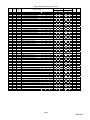
Table 7.4 Group Channel List (3/11)
Unit
No.
0
0
0
0
0
0
0
0
0
0
0
0
0
0
0
0
0
0
0
0
0
0
0
1
1
1
1
1
1
1
1
1
0
0
0
0
0
0
0
1
1
1
1
1
1
1
1
1
Group Channel
(h)
(h)
0D
0D
0D
0D
0D
0D
0D
0D
0D
0D
0D
0D
0F
0F
0F
63
4D
4F
51
53
55
57
59
5B
5D
5F
61
79
79
79
79
79
76
76
76
76
76
76
76
76
76
76
76
79
79
79
79
79
01
21
41
61
02
22
42
62
05
25
45
65
01
02
05
21
21
21
21
21
21
21
21
21
21
21
21
02
04
06
08
0A
86
73
75
77
79
7B
7D
7F
81
83
85
72
74
76
78
7A
ME96SSH-MB
Name of Cannel
Total power factor
Phase 1 power factor
Phase 2 power factor
Phase 3 power factor
Total power factor
Phase 1 power factor
Phase 2 power factor
Phase 3 power factor
Total power factor
Phase 1 power factor
Phase 2 power factor
Phase 3 power factor
Frequency
Frequency
Frequency
1-2 harmonic voltage
1-2 harmonic voltage
1-2 harmonic voltage
1-2 harmonic voltage
1-2 harmonic voltage
1-2 harmonic voltage
1-2 harmonic voltage
1-2 harmonic voltage
1-2 harmonic voltage
1-2 harmonic voltage
1-2 harmonic voltage
1-2 harmonic voltage
1-2 harmonic voltage
1-2 harmonic voltage
1-2 harmonic voltage
1-2 harmonic voltage
1-2 harmonic voltage
1-2 voltage THD
1-2 voltage harmonic distortion
1-2 voltage harmonic distortion
1-2 voltage harmonic distortion
1-2 voltage harmonic distortion
1-2 voltage harmonic distortion
1-2 voltage harmonic distortion
1-2 voltage harmonic distortion
1-2 voltage harmonic distortion
1-2 voltage harmonic distortion
1-2 voltage harmonic distortion
1-2 voltage harmonic distortion
1-2 voltage harmonic distortion
1-2 voltage harmonic distortion
1-2 voltage harmonic distortion
1-2 voltage harmonic distortion
ME96SSR-MB Data
Note
type
3P3W
3P3W
3P4W
1P2W 3P4W
1P2W
1P3W
1P3W
%
%
%
%
%
%
%
%
%
%
%
%
Hz
Hz
Hz
V
V
V
V
V
V
V
V
V
V
V
V
V
V
V
V
V
%
%
%
%
%
%
%
%
%
%
%
%
%
%
%
%
Inst.
Inst.
Inst.
Inst.
max.
max.
max.
max.
min.
min.
min.
min.
Inst.
max.
min.
Inst.
Inst.
Inst.
Inst.
Inst.
Inst.
Inst.
Inst.
Inst.
Inst.
Inst.
Inst.
Inst.
Inst.
Inst.
Inst.
Inst.
Inst.
Inst.
Inst.
Inst.
Inst.
Inst.
Inst.
Inst.
Inst.
Inst.
Inst.
Inst.
Inst.
Inst.
Inst.
Inst.
Total
1st
3rd
5th
7th
9th
11th
13th
15th
17th
19th
21st
23rd
25th
27th
29th
31st
Total
3rd
5th
7th
9th
11th
13th
15th
17th
19th
21st
23rd
25th
27th
29th
31st
○
○
○
○
○
○
○
○
○
○
○
○
○
○
○
-
○
○
○
○
○
○
○
○
○
○
○
○
○
○
○
○
○
○
○
○
○
○
○
○
○
○
○
○
○
○
○
○
○
○
○
○
○
○
○
○
○
○
○
○
○
○
○
○
○
○
○
○
○
○
○
○
○
○
○
○
○
○
○
○
○
○
○
○
○
○
○
○
○
○
○
○
○
○
○
○
○
○
○
○
○
○
○
○
○
○
○
○
○
-
○
○
○
○
○
○
○
○
○
○
○
○
○
○
○
○
○
○
○
○
○
-
○
○
○
○
○
○
○
○
○
○
○
○
○
○
○
○
○
○
○
○
○
-
①
①
①
①
①
①
①
①
①
①
①
①
①
①
①
①
①
①
①
①
①
①
①
①
①
①
①
①
①
①
①
①
①
①
①
①
①
①
①
①
①
①
①
①
①
①
①
①
(31/n)
LEN130391
Table 7.5 Group Channel List (4/11)
Unit
No.
0
0
0
0
0
0
0
0
1
1
1
1
1
1
1
1
1
0
0
0
0
0
0
0
1
1
1
1
1
1
1
1
1
0
0
0
0
0
0
0
0
1
1
1
1
1
1
1
1
1
Group Channel
(h)
(h)
63
4D
4F
51
53
55
57
59
5B
5D
5F
61
79
79
79
79
79
76
76
76
76
76
76
76
76
76
76
76
79
79
79
79
79
76
4D
76
76
76
76
76
76
76
76
76
76
79
79
79
79
79
41
41
41
41
41
41
41
41
41
41
41
41
18
1A
1C
1E
20
9C
89
8B
8D
8F
91
93
95
97
99
9B
88
8A
8C
8E
90
DE
A2
CB
CD
CF
D1
D3
D5
D7
D9
DB
DD
CA
CC
CE
D0
D2
ME96SSH-MB
Name of Cannel
2-3 harmonic voltage
2-3 harmonic voltage
2-3 harmonic voltage
2-3 harmonic voltage
2-3 harmonic voltage
2-3 harmonic voltage
2-3 harmonic voltage
2-3 harmonic voltage
2-3 harmonic voltage
2-3 harmonic voltage
2-3 harmonic voltage
2-3 harmonic voltage
2-3 harmonic voltage
2-3 harmonic voltage
2-3 harmonic voltage
2-3 harmonic voltage
2-3 harmonic voltage
2-3 voltage THD
2-3 voltage harmonic distortion
2-3 voltage harmonic distortion
2-3 voltage harmonic distortion
2-3 voltage harmonic distortion
2-3 voltage harmonic distortion
2-3 voltage harmonic distortion
2-3 voltage harmonic distortion
2-3 voltage harmonic distortion
2-3 voltage harmonic distortion
2-3 voltage harmonic distortion
2-3 voltage harmonic distortion
2-3 voltage harmonic distortion
2-3 voltage harmonic distortion
2-3 voltage harmonic distortion
2-3 voltage harmonic distortion
L-L voltage THD
L-L harmonic voltage
L-L voltage harmonic distortion
L-L voltage harmonic distortion
L-L voltage harmonic distortion
L-L voltage harmonic distortion
L-L voltage harmonic distortion
L-L voltage harmonic distortion
L-L voltage harmonic distortion
L-L voltage harmonic distortion
L-L voltage harmonic distortion
L-L voltage harmonic distortion
L-L voltage harmonic distortion
L-L voltage harmonic distortion
L-L voltage harmonic distortion
L-L voltage harmonic distortion
L-L voltage harmonic distortion
ME96SSR-MB Data
Note
type
3P3W
3P3W
3P4W
1P2W 3P4W
1P2W
1P3W
1P3W
V
V
V
V
V
V
V
V
V
V
V
V
V
V
V
V
V
%
%
%
%
%
%
%
%
%
%
%
%
%
%
%
%
%
V
%
%
%
%
%
%
%
%
%
%
%
%
%
%
%
Inst.
Inst.
Inst.
Inst.
Inst.
Inst.
Inst.
Inst.
Inst.
Inst.
Inst.
Inst.
Inst.
Inst.
Inst.
Inst.
Inst.
Inst.
Inst.
Inst.
Inst.
Inst.
Inst.
Inst.
Inst.
Inst.
Inst.
Inst.
Inst.
Inst.
Inst.
Inst.
Inst.
max.
max.
max.
max.
max.
max.
max.
max.
max.
max.
max.
max.
max.
max.
max.
max.
max.
Total
1st
3rd
5th
7th
9th
11th
13th
15th
17th
19th
21st
23rd
25th
27th
29th
31st
Total
3rd
5th
7th
9th
11th
13th
15th
17th
19th
21st
23rd
25th
27th
29th
31st
Total
1st
3rd
5th
7th
9th
11th
13th
15th
17th
19th
21st
23rd
25th
27th
29th
31st
-
○
○
○
○
○
○
○
○
○
○
○
○
○
○
○
○
○
○
○
○
○
○
○
○
○
○
○
○
○
○
○
○
○
○
○
○
○
○
○
○
○
○
○
○
○
○
○
○
○
○
○
○
○
○
○
○
○
○
○
○
○
○
○
○
○
○
○
-
○
○
○
○
○
○
○
○
○
○
○
○
○
○
○
○
○
○
○
○
○
○
○
-
○
○
○
○
○
○
○
○
-
①
①
①
①
①
①
①
①
①
①
①
①
①
①
①
①
①
①
①
①
①
①
①
①
①
①
①
①
①
①
①
①
①
①
①
①
①
①
①
①
①
①
①
①
①
①
①
①
①
①
(32/n)
LEN130391
Table 7.6 Group Channel List (5/11)
Unit
No.
0
0
1
1
1
1
1
1
1
1
1
1
1
1
1
1
1
0
0
0
0
0
0
0
1
1
1
1
1
1
1
1
1
0
0
1
1
1
1
1
1
1
1
1
1
1
1
1
1
1
Group Channel
(h)
(h)
4B
35
37
39
3B
3D
3F
41
43
45
47
49
7A
7A
7A
7A
7A
77
77
77
77
77
77
77
77
77
77
77
7A
7A
7A
7A
7A
4B
35
37
39
3B
3D
3F
41
43
45
47
49
7A
7A
7A
7A
7A
21
21
21
21
21
21
21
21
21
21
21
21
02
04
06
08
0A
86
73
75
77
79
7B
7D
7F
81
83
85
72
74
76
78
7A
41
41
41
41
41
41
41
41
41
41
41
41
18
1A
1C
1E
20
ME96SSH-MB
Name of Cannel
1-N harmonic voltage
1-N harmonic voltage
1-N harmonic voltage
1-N harmonic voltage
1-N harmonic voltage
1-N harmonic voltage
1-N harmonic voltage
1-N harmonic voltage
1-N harmonic voltage
1-N harmonic voltage
1-N harmonic voltage
1-N harmonic voltage
1-N harmonic voltage
1-N harmonic voltage
1-N harmonic voltage
1-N harmonic voltage
1-N harmonic voltage
1-N voltage THD
1-N voltage harmonic distortion
1-N voltage harmonic distortion
1-N voltage harmonic distortion
1-N voltage harmonic distortion
1-N voltage harmonic distortion
1-N voltage harmonic distortion
1-N voltage harmonic distortion
1-N voltage harmonic distortion
1-N voltage harmonic distortion
1-N voltage harmonic distortion
1-N voltage harmonic distortion
1-N voltage harmonic distortion
1-N voltage harmonic distortion
1-N voltage harmonic distortion
1-N voltage harmonic distortion
2-N harmonic voltage
2-N harmonic voltage
2-N harmonic voltage
2-N harmonic voltage
2-N harmonic voltage
2-N harmonic voltage
2-N harmonic voltage
2-N harmonic voltage
2-N harmonic voltage
2-N harmonic voltage
2-N harmonic voltage
2-N harmonic voltage
2-N harmonic voltage
2-N harmonic voltage
2-N harmonic voltage
2-N harmonic voltage
2-N harmonic voltage
ME96SSR-MB Data
Note
type
3P3W
3P3W
3P4W
1P2W 3P4W
1P2W
1P3W
1P3W
V
V
V
V
V
V
V
V
V
V
V
V
V
V
V
V
V
%
%
%
%
%
%
%
%
%
%
%
%
%
%
%
%
V
V
V
V
V
V
V
V
V
V
V
V
V
V
V
V
V
Inst.
Inst.
Inst.
Inst.
Inst.
Inst.
Inst.
Inst.
Inst.
Inst.
Inst.
Inst.
Inst.
Inst.
Inst.
Inst.
Inst.
Inst.
Inst.
Inst.
Inst.
Inst.
Inst.
Inst.
Inst.
Inst.
Inst.
Inst.
Inst.
Inst.
Inst.
Inst.
Inst.
Inst.
Inst.
Inst.
Inst.
Inst.
Inst.
Inst.
Inst.
Inst.
Inst.
Inst.
Inst.
Inst.
Inst.
Inst.
Inst.
Inst.
Total
1st
3rd
5th
7th
9th
11th
13th
15th
17th
19th
21st
23rd
25th
27th
29th
31st
Total
3rd
5th
7th
9th
11th
13th
15th
17th
19th
21st
23rd
25th
27th
29th
31st
Total
1st
3rd
5th
7th
9th
11th
13th
15th
17th
19th
21st
23rd
25th
27th
29th
31st
○
○
○
○
○
○
○
○
○
○
○
○
○
○
○
○
○
○
○
○
○
○
○
○
○
○
○
○
○
○
○
○
○
○
○
○
○
○
○
○
○
○
○
○
○
○
○
○
○
○
-
-
○
○
○
○
○
○
○
○
○
○
○
○
○
○
○
○
○
○
○
○
○
○
○
-
-
-
①
①
①
①
①
①
①
①
①
①
①
①
①
①
①
①
①
①
①
①
①
①
①
①
①
①
①
①
①
①
①
①
①
①
①
①
①
①
①
①
①
①
①
①
①
①
①
①
①
①
(33/n)
LEN130391
Table 7.7 Group Channel List (6/11)
Unit
No.
0
0
0
0
0
0
0
1
1
1
1
1
1
1
1
1
0
0
1
1
1
1
1
1
1
1
1
1
1
1
1
1
1
0
0
0
0
0
0
0
1
1
1
1
1
1
1
1
1
Group Channel
(h)
(h)
77
77
77
77
77
77
77
77
77
77
77
7A
7A
7A
7A
7A
4B
35
37
39
3B
3D
3F
41
43
45
47
49
7A
7A
7A
7A
7A
77
77
77
77
77
77
77
77
77
77
77
7A
7A
7A
7A
7A
9C
89
8B
8D
8F
91
93
95
97
99
9B
88
8A
8C
8E
90
61
61
61
61
61
61
61
61
61
61
61
61
2E
30
32
34
36
B2
9F
A1
A3
A5
A7
A9
AB
AD
AF
B1
9E
A0
A2
A4
A6
ME96SSH-MB
Name of Cannel
2-N voltage THD
2-N voltage harmonic distortion
2-N voltage harmonic distortion
2-N voltage harmonic distortion
2-N voltage harmonic distortion
2-N voltage harmonic distortion
2-N voltage harmonic distortion
2-N voltage harmonic distortion
2-N voltage harmonic distortion
2-N voltage harmonic distortion
2-N voltage harmonic distortion
2-N voltage harmonic distortion
2-N voltage harmonic distortion
2-N voltage harmonic distortion
2-N voltage harmonic distortion
2-N voltage harmonic distortion
3-N harmonic voltage
3-N harmonic voltage
3-N harmonic voltage
3-N harmonic voltage
3-N harmonic voltage
3-N harmonic voltage
3-N harmonic voltage
3-N harmonic voltage
3-N harmonic voltage
3-N harmonic voltage
3-N harmonic voltage
3-N harmonic voltage
3-N harmonic voltage
3-N harmonic voltage
3-N harmonic voltage
3-N harmonic voltage
3-N harmonic voltage
3-N voltage THD
3-N voltage harmonic distortion
3-N voltage harmonic distortion
3-N voltage harmonic distortion
3-N voltage harmonic distortion
3-N voltage harmonic distortion
3-N voltage harmonic distortion
3-N voltage harmonic distortion
3-N voltage harmonic distortion
3-N voltage harmonic distortion
3-N voltage harmonic distortion
3-N voltage harmonic distortion
3-N voltage harmonic distortion
3-N voltage harmonic distortion
3-N voltage harmonic distortion
3-N voltage harmonic distortion
ME96SSR-MB Data
Note
type
3P3W
3P3W
3P4W
1P2W 3P4W
1P2W
1P3W
1P3W
%
%
%
%
%
%
%
%
%
%
%
%
%
%
%
%
V
V
V
V
V
V
V
V
V
V
V
V
V
V
V
V
V
%
%
%
%
%
%
%
%
%
%
%
%
%
%
%
%
Inst.
Inst.
Inst.
Inst.
Inst.
Inst.
Inst.
Inst.
Inst.
Inst.
Inst.
Inst.
Inst.
Inst.
Inst.
Inst.
Inst.
Inst.
Inst.
Inst.
Inst.
Inst.
Inst.
Inst.
Inst.
Inst.
Inst.
Inst.
Inst.
Inst.
Inst.
Inst.
Inst.
Inst.
Inst.
Inst.
Inst.
Inst.
Inst.
Inst.
Inst.
Inst.
Inst.
Inst.
Inst.
Inst.
Inst.
Inst.
Inst.
Total
3rd
5th
7th
9th
11th
13th
15th
17th
19th
21st
23rd
25th
27th
29th
31st
Total
1st
3rd
5th
7th
9th
11th
13th
15th
17th
19th
21st
23rd
25th
27th
29th
31st
Total
3rd
5th
7th
9th
11th
13th
15th
17th
19th
21st
23rd
25th
27th
29th
31st
○
○
○
○
○
○
○
○
○
○
○
○
○
○
○
○
○
○
○
○
○
○
○
○
○
○
○
○
○
○
○
○
○
○
○
○
○
○
○
○
○
○
○
○
○
○
○
○
○
-
-
○
○
○
○
○
○
○
○
○
○
○
○
○
○
○
○
○
○
○
○
○
○
-
-
-
①
①
①
①
①
①
①
①
①
①
①
①
①
①
①
①
①
①
①
①
①
①
①
①
①
①
①
①
①
①
①
①
①
①
①
①
①
①
①
①
①
①
①
①
①
①
①
①
①
(34/n)
LEN130391
Table 7.8 Group Channel List (7/11)
Unit
No.
0
0
0
0
0
0
0
0
1
1
1
1
1
1
1
1
1
0
0
0
0
0
0
0
0
1
1
1
1
1
1
1
1
1
0
1/0
1/0
1/0
1/0
1/0
1/0
1
1
1
1
1
1
1
1
1
Group Channel
(h)
(h)
77
35
77
77
77
77
77
77
77
77
77
77
7A
7A
7A
7A
7A
33
1D
1F
21
23
25
27
29
2B
2D
2F
31
78
78
78
78
78
75
75
75
75
75
75
75
75
75
75
75
78
78
78
78
78
DE
A2
CB
CD
CF
D1
D3
D5
D7
D9
DB
DD
CA
CC
CE
D0
D2
21
21
21
21
21
21
21
21
21
21
21
21
02
04
06
08
0A
86
73
75
77
79
7B
7D
7F
81
83
85
72
74
76
78
7A
ME96SSH-MB
Name of Cannel
L-N voltage THD
L-N harmonic voltage
L-N voltage harmonic distortion
L-N voltage harmonic distortion
L-N voltage harmonic distortion
L-N voltage harmonic distortion
L-N voltage harmonic distortion
L-N voltage harmonic distortion
L-N voltage harmonic distortion
L-N voltage harmonic distortion
L-N voltage harmonic distortion
L-N voltage harmonic distortion
L-N voltage harmonic distortion
L-N voltage harmonic distortion
L-N voltage harmonic distortion
L-N voltage harmonic distortion
L-N voltage harmonic distortion
Phase 1 harmonic current
Phase 1 harmonic current
Phase 1 harmonic current
Phase 1 harmonic current
Phase 1 harmonic current
Phase 1 harmonic current
Phase 1 harmonic current
Phase 1 harmonic current
Phase 1 harmonic current
Phase 1 harmonic current
Phase 1 harmonic current
Phase 1 harmonic current
Phase 1 harmonic current
Phase 1 harmonic current
Phase 1 harmonic current
Phase 1 harmonic current
Phase 1 harmonic current
Phase 1 current THD
Phase 1 current harmonic distortion
Phase 1 current harmonic distortion
Phase 1 current harmonic distortion
Phase 1 current harmonic distortion
Phase 1 current harmonic distortion
Phase 1 current harmonic distortion
Phase 1 current harmonic distortion
Phase 1 current harmonic distortion
Phase 1 current harmonic distortion
Phase 1 current harmonic distortion
Phase 1 current harmonic distortion
Phase 1 current harmonic distortion
Phase 1 current harmonic distortion
Phase 1 current harmonic distortion
Phase 1 current harmonic distortion
ME96SSR-MB Data
Note
type
3P3W
3P3W
3P4W
1P2W 3P4W
1P2W
1P3W
1P3W
%
V
%
%
%
%
%
%
%
%
%
%
%
%
%
%
%
A
A
A
A
A
A
A
A
A
A
A
A
A
A
A
A
A
%
%
%
%
%
%
%
%
%
%
%
%
%
%
%
%
max.
max.
max.
max.
max.
max.
max.
max.
max.
max.
max.
max.
max.
max.
max.
max.
max.
Inst.
Inst.
Inst.
Inst.
Inst.
Inst.
Inst.
Inst.
Inst.
Inst.
Inst.
Inst.
Inst.
Inst.
Inst.
Inst.
Inst.
Inst.
Inst.
Inst.
Inst.
Inst.
Inst.
Inst.
Inst.
Inst.
Inst.
Inst.
Inst.
Inst.
Inst.
Inst.
Inst.
Total
1st
3rd
5th
7th
9th
11th
13th
15th
17th
19th
21st
23rd
25th
27th
29th
31st
Total
1st
3rd
5th
7th
9th
11th
13th
15th
17th
19th
21st
23rd
25th
27th
29th
31st
Total
3rd
5th
7th
9th
11th
13th
15th
17th
19th
21st
23rd
25th
27th
29th
31st
○
○
○
○
○
○
○
○
○
○
○
○
○
○
○
○
○
○
○
○
○
○
○
○
○
○
○
○
○
○
○
○
○
○
○
○
○
○
○
○
○
○
○
○
○
○
○
○
○
○
○
○
○
○
○
○
○
○
○
○
○
○
○
○
○
○
○
○
○
○
○
○
○
○
○
○
○
○
○
○
○
○
○
○
○
○
○
○
○
○
○
○
○
○
○
○
○
○
○
○
○
○
○
○
○
○
○
○
○
○
○
○
○
○
○
○
○
○
○
○
○
○
○
○
○
○
○
○
○
○
○
○
○
○
○
○
○
○
○
-
○
○
○
○
○
○
○
○
○
○
○
○
○
○
○
-
○
○
○
○
○
○
○
○
○
○
○
○
○
○
○
-
①
①
①
①
①
①
①
①
①
①
①
①
①
①
①
①
①
①
①
①
①
①
①
①
①
①
①
①
①
①
①
①
①
①
①
①
①
①
①
①
①
①
①
①
①
①
①
①
①
①
*2
*2
*2
*2
*2
*2
(35/n)
LEN130391
Table 7.9 Group Channel List (8/11)
Unit
No.
0
0
0
0
0
0
0
0
1
1
1
1
1
1
1
1
1
0
1/0
1/0
1/0
1/0
1/0
1/0
1
1
1
1
1
1
1
1
1
0
0
0
0
0
0
0
0
1
1
1
1
1
1
1
1
1
Group Channel
(h)
(h)
33
1D
1F
21
23
25
27
29
2B
2D
2F
31
78
78
78
78
78
75
75
75
75
75
75
75
75
75
75
75
78
78
78
78
78
33
1D
1F
21
23
25
27
29
2B
2D
2F
31
78
78
78
78
78
41
41
41
41
41
41
41
41
41
41
41
41
18
1A
1C
1E
20
9C
89
8B
8D
8F
91
93
95
97
99
9B
88
8A
8C
8E
90
61
61
61
61
61
61
61
61
61
61
61
61
2E
30
32
34
36
ME96SSH-MB
Name of Cannel
Phase 2 harmonic current
Phase 2 harmonic current
Phase 2 harmonic current
Phase 2 harmonic current
Phase 2 harmonic current
Phase 2 harmonic current
Phase 2 harmonic current
Phase 2 harmonic current
Phase 2 harmonic current
Phase 2 harmonic current
Phase 2 harmonic current
Phase 2 harmonic current
Phase 2 harmonic current
Phase 2 harmonic current
Phase 2 harmonic current
Phase 2 harmonic current
Phase 2 harmonic current
Phase 2 current THD
Phase 2 current harmonic distortion
Phase 2 current harmonic distortion
Phase 2 current harmonic distortion
Phase 2 current harmonic distortion
Phase 2 current harmonic distortion
Phase 2 current harmonic distortion
Phase 2 current harmonic distortion
Phase 2 current harmonic distortion
Phase 2 current harmonic distortion
Phase 2 current harmonic distortion
Phase 2 current harmonic distortion
Phase 2 current harmonic distortion
Phase 2 current harmonic distortion
Phase 2 current harmonic distortion
Phase 2 current harmonic distortion
Phase 3 harmonic current
Phase 3 harmonic current
Phase 3 harmonic current
Phase 3 harmonic current
Phase 3 harmonic current
Phase 3 harmonic current
Phase 3 harmonic current
Phase 3 harmonic current
Phase 3 harmonic current
Phase 3 harmonic current
Phase 3 harmonic current
Phase 3 harmonic current
Phase 3 harmonic current
Phase 3 harmonic current
Phase 3 harmonic current
Phase 3 harmonic current
Phase 3 harmonic current
ME96SSR-MB Data
Note
type
3P3W
3P3W
3P4W
1P2W 3P4W
1P2W
1P3W
1P3W
A
A
A
A
A
A
A
A
A
A
A
A
A
A
A
A
A
%
%
%
%
%
%
%
%
%
%
%
%
%
%
%
%
A
A
A
A
A
A
A
A
A
A
A
A
A
A
A
A
A
Inst.
Inst.
Inst.
Inst.
Inst.
Inst.
Inst.
Inst.
Inst.
Inst.
Inst.
Inst.
Inst.
Inst.
Inst.
Inst.
Inst.
Inst.
Inst.
Inst.
Inst.
Inst.
Inst.
Inst.
Inst.
Inst.
Inst.
Inst.
Inst.
Inst.
Inst.
Inst.
Inst.
Inst.
Inst.
Inst.
Inst.
Inst.
Inst.
Inst.
Inst.
Inst.
Inst.
Inst.
Inst.
Inst.
Inst.
Inst.
Inst.
Inst.
Total
1st
3rd
5th
7th
9th
11th
13th
15th
17th
19th
21st
23rd
25th
27th
29th
31st
Total
3rd
5th
7th
9th
11th
13th
15th
17th
19th
21st
23rd
25th
27th
29th
31st
Total
1st
3rd
5th
7th
9th
11th
13th
15th
17th
19th
21st
23rd
25th
27th
29th
31st
○
○
○
○
○
○
○
○
○
○
○
○
○
○
○
○
○
○
○
○
○
○
○
○
○
○
○
○
○
○
○
○
○
○
○
○
○
○
○
○
○
○
○
○
○
○
○
○
○
○
△
△
△
△
△
△
△
△
△
△
△
△
△
△
△
△
△
△
△
△
△
△
△
△
△
△
△
△
△
△
△
△
△
○
○
○
○
○
○
○
○
○
○
○
○
○
○
○
○
○
-
○
○
○
○
○
○
○
○
○
○
○
○
○
○
○
○
○
○
○
○
○
○
○
-
△
△
△
△
△
△
△
△
△
△
△
△
△
△
△
○
○
○
○
○
○
○
○
-
-
①
①
①
①
①
①
①
①
①
①
①
①
①
①
①
①
①
①
①
①
①
①
①
①
①
①
①
①
①
①
①
①
①
①
①
①
①
①
①
①
①
①
①
①
①
①
①
①
①
①
*1
*1
*1
*1
*1
*1
*1
*1
*1
*1
*1
*1
*1
*1
*1
*1
*1
*1
*1,*2
*1,*2
*1,*2
*1,*2
*1,*2
*1,*2
*1
*1
*1
*1
*1
*1
*1
*1
*1
(36/n)
LEN130391
Table 7.10 Group Channel List (9/11)
Unit
No.
0
1/0
1/0
1/0
1/0
1/0
1/0
1
1
1
1
1
1
1
1
1
0
0
0
0
0
0
0
0
1
1
1
1
1
1
1
1
1
1
1
1
1
1
1
1
1
1
1
1
1
1
1
1
1
1
Group Channel
(h)
(h)
75
75
75
75
75
75
75
75
75
75
75
78
78
78
78
78
33
1D
1F
21
23
25
27
29
2B
2D
2F
31
78
78
78
78
78
33
1D
1F
21
23
25
27
29
2B
2D
2F
31
7B
7B
7B
7B
7B
B2
9F
A1
A3
A5
A7
A9
AB
AD
AF
B1
9E
A0
A2
A4
A6
81
81
81
81
81
81
81
81
81
81
81
81
44
46
48
4A
4C
82
82
82
82
82
82
82
82
82
82
82
82
44
46
48
4A
4C
ME96SSH-MB
Name of Cannel
Phase 3 current THD
Phase 3 current harmonic distortion
Phase 3 current harmonic distortion
Phase 3 current harmonic distortion
Phase 3 current harmonic distortion
Phase 3 current harmonic distortion
Phase 3 current harmonic distortion
Phase 3 current harmonic distortion
Phase 3 current harmonic distortion
Phase 3 current harmonic distortion
Phase 3 current harmonic distortion
Phase 3 current harmonic distortion
Phase 3 current harmonic distortion
Phase 3 current harmonic distortion
Phase 3 current harmonic distortion
Phase 3 current harmonic distortion
Phase N harmonic current
Phase N harmonic current
Phase N harmonic current
Phase N harmonic current
Phase N harmonic current
Phase N harmonic current
Phase N harmonic current
Phase N harmonic current
Phase N harmonic current
Phase N harmonic current
Phase N harmonic current
Phase N harmonic current
Phase N harmonic current
Phase N harmonic current
Phase N harmonic current
Phase N harmonic current
Phase N harmonic current
Phase N current THD
Phase N current harmonic distortion
Phase N current harmonic distortion
Phase N current harmonic distortion
Phase N current harmonic distortion
Phase N current harmonic distortion
Phase N current harmonic distortion
Phase N current harmonic distortion
Phase N current harmonic distortion
Phase N current harmonic distortion
Phase N current harmonic distortion
Phase N current harmonic distortion
Phase N current harmonic distortion
Phase N current harmonic distortion
Phase N current harmonic distortion
Phase N current harmonic distortion
Phase N current harmonic distortion
ME96SSR-MB Data
Note
type
3P3W
3P3W
3P4W
1P2W 3P4W
1P2W
1P3W
1P3W
%
%
%
%
%
%
%
%
%
%
%
%
%
%
%
%
A
A
A
A
A
A
A
A
A
A
A
A
A
A
A
A
A
A
A
A
A
A
A
A
A
A
A
A
A
A
A
A
A
A
Inst.
Inst.
Inst.
Inst.
Inst.
Inst.
Inst.
Inst.
Inst.
Inst.
Inst.
Inst.
Inst.
Inst.
Inst.
Inst.
Inst.
Inst.
Inst.
Inst.
Inst.
Inst.
Inst.
Inst.
Inst.
Inst.
Inst.
Inst.
Inst.
Inst.
Inst.
Inst.
Inst.
max.
max.
max.
max.
max.
max.
max.
max.
max.
max.
max.
max.
max.
max.
max.
max.
max.
Total
3rd
5th
7th
9th
11th
13th
15th
17th
19th
21st
23rd
25th
27th
29th
31st
Total
1st
3rd
5th
7th
9th
11th
13th
15th
17th
19th
21st
23rd
25th
27th
29th
31st
Total
1st
3rd
5th
7th
9th
11th
13th
15th
17th
19th
21st
23rd
25th
27th
29th
31st
○
○
○
○
○
○
○
○
○
○
○
○
○
○
○
○
○
○
○
○
○
○
○
○
○
○
○
○
○
○
○
○
○
○
○
○
○
○
○
○
○
○
○
○
○
○
○
○
○
○
○
○
○
○
○
○
○
○
○
○
○
○
○
○
○
○
-
-
○
○
○
○
○
○
○
○
○
○
○
○
○
○
○
○
○
○
○
○
○
○
○
-
○
○
○
○
○
○
○
-
-
①
①
①
①
①
①
①
①
①
①
①
①
①
①
①
①
①
①
①
①
①
①
①
①
①
①
①
①
①
①
①
①
①
①
①
①
①
①
①
①
①
①
①
①
①
①
①
①
①
①
*2
*2
*2
*2
*2
*2
(37/n)
LEN130391
Table 7.11 Group Channel List (10/11)
Unit
No.
0
0
0
0
0
0
0
0
1
1
1
1
1
1
1
1
1
0
0
0
0
0
0
0
0
0
0
0
0
0
0
0
0
0
1
1
1
1
1
1
1
1
1
1
1
1
1
1
1
1
1
1
1
1
1
1
1
1
1
1
1
Group Channel
(h)
(h)
33
1D
1F
21
23
25
27
29
2B
2D
2F
31
78
78
78
78
78
80
80
80
80
81
81
81
81
81
81
81
81
82
8B
8C
87
88
B0
B0
B0
B0
B0
B0
B0
B0
B0
B0
B0
B0
B0
B0
B0
B0
B0
B0
B0
B0
B0
B0
B0
B0
B0
B0
B0
A2
A2
A2
A2
A2
A2
A2
A2
A2
A2
A2
A2
5A
5C
5E
60
62
01
63
64
65
01
63
64
65
66
67
68
69
01
01
01
01
01
01
04
07
0A
0D
10
13
16
19
02
05
08
0B
0E
11
14
17
1A
03
06
09
0C
0F
12
15
18
1B
ME96SSH-MB
Name of Cannel
Harmonic current
Harmonic current
Harmonic current
Harmonic current
Harmonic current
Harmonic current
Harmonic current
Harmonic current
Harmonic current
Harmonic current
Harmonic current
Harmonic current
Harmonic current
Harmonic current
Harmonic current
Harmonic current
Harmonic current
Active energy import
Active energy export
Active energy import
Active energy export
Reactive energy import lag
Reactive energy export lag
Reactive energy import lead
Reactive energy export lead
Reactive energy import lag
Reactive energy export lag
Reactive energy import lead
Reactive energy export lead
Apparent energy
Periodic active energy(Period 1)
Periodic active energy(Period 2)
Operating time1
Operating time2
Active energy import
Active energy export
Reactive energy import lag
Reactive energy export lag
Reactive energy import lead
Reactive energy export lead
Apparent energy
Periodic active energy(Period 1)
Periodic active energy(Period 2)
Active energy import
Active energy export
Reactive energy import lag
Reactive energy export lag
Reactive energy import lead
Reactive energy export lead
Apparent energy
Periodic active energy(Period 1)
Periodic active energy(Period 2)
Active energy import
Active energy export
Reactive energy import lag
Reactive energy export lag
Reactive energy import lead
Reactive energy export lead
Apparent energy
Periodic active energy(Period 1)
Periodic active energy(Period 2)
A
A
A
A
A
A
A
A
A
A
A
A
A
A
A
A
A
kWh
kWh
kWh
kWh
kvarh
kvarh
kvarh
kvarh
kvarh
kvarh
kvarh
kvarh
kVAh
kWh
kWh
h
h
Wh
Wh
varh
varh
varh
varh
VAh
Wh
Wh
kWh
kWh
kvarh
kvarh
kvarh
kvarh
kVAh
kWh
kWh
MWh
MWh
Mvarh
Mvarh
Mvarh
Mvarh
MVAh
MWh
MWh
ME96SSR-MB Data
Note
type
3P3W
3P3W
3P4W
1P2W 3P4W
1P2W
1P3W
1P3W
max.
max.
max.
max.
max.
max.
max.
max.
max.
max.
max.
max.
max.
max.
max.
max.
max.
count
count
count
count
count
count
count
count
count
count
count
count
count
count
count
count
count
count
count
count
count
count
count
count
count
count
count
count
count
count
count
count
count
count
count
count
count
count
count
count
count
count
count
count
Total
1st
3rd
5th
7th
9th
11th
13th
15th
17th
19th
21st
23rd
25th
27th
29th
31st
expand
expand
expand
expand
expand
expand
unit fixed
unit fixed
unit fixed
unit fixed
unit fixed
unit fixed
unit fixed
unit fixed
unit fixed
unit fixed
unit fixed
unit fixed
unit fixed
unit fixed
unit fixed
unit fixed
unit fixed
unit fixed
unit fixed
unit fixed
unit fixed
unit fixed
unit fixed
unit fixed
unit fixed
unit fixed
unit fixed
○
○
○
○
○
○
○
○
○
○
○
○
○
○
○
○
○
○
○
○
○
○
○
○
○
○
○
○
○
○
○
○
○
○
○
○
○
○
○
○
○
○
○
○
○
○
○
○
○
○
○
○
○
○
○
○
○
○
○
○
○
○
○
○
○
○
○
○
○
○
○
○
○
○
○
○
○
○
○
○
○
○
○
○
○
○
○
○
○
○
○
○
○
○
○
○
○
○
○
○
○
○
○
○
○
○
○
○
○
○
○
○
○
○
○
○
○
○
○
○
○
○
○
○
○
○
○
○
○
○
○
○
○
○
○
○
○
○
○
○
○
○
○
○
○
○
○
○
○
○
○
○
○
○
○
○
○
○
○
○
○
○
○
○
○
○
○
○
○
○
○
○
○
○
○
○
○
○
○
○
○
○
○
○
○
○
○
○
○
○
○
○
○
○
○
○
○
○
○
○
○
○
○
○
○
○
○
○
○
○
○
○
○
○
○
○
○
○
○
○
○
○
○
○
○
○
○
○
○
○
○
○
○
○
○
○
○
○
○
○
○
○
○
○
○
○
○
○
○
○
○
○
○
○
○
○
○
○
○
○
○
○
○
○
○
○
○
○
○
○
○
○
○
○
○
○
○
○
○
○
○
○
○
○
○
○
○
○
○
○
○
○
○
○
○
○
○
○
○
○
○
○
○
○
○
○
○
○
○
○
○
○
○
○
○
○
○
○
○
①
①
①
①
①
①
①
①
①
①
①
①
①
①
①
①
①
②
②
②
②
②
②
②
②
②
②
②
②
②
②
②
②
②
③
③
③
③
③
③
③
③
③
③
③
③
③
③
③
③
③
③
③
③
③
③
③
③
③
③
③
*3
*3
*3
*3
*3
*3
*3
*3
*3
*3
*3
*3
*3
*3
*3
*3
*3
*3
*3
*3
*3
*3
*3
*3
*3
*3
*3
*3
*3
*3
*3
*3
*3
*3
*3
*3
*3
*3
*3
*3
*3
*3
(38/n)
LEN130391
Table 7.12 Group Channel List (11/11)
Unit
No.
0
0
0
0
0
0
0
0
0
0
0
0
0
0
0
0
0
0
0
0
0
0
0
0
0
Group Channel
(h)
(h)
01
01
01
02
02
02
05
05
03
03
07
07
08
09
09
0D
0D
0F
0F
77
76
75
75
A0
A0
14
15
94
14
15
94
14
15
14
15
14
15
14
14
15
14
15
14
15
E1
E1
E1
F1
31
35
ME96SSH-MB
Name of Cannel
Current upper limit
Current lower limit
Current upper limit
Current demand upper limit
Current demand lower limit
Current demand upper limit
Voltage upper limit(L-L)
Voltage lower limit(L-L)
Voltage upper limit(L-N)
Voltage lower limit(L-N)
Active power upper limit
Active power lower limit
Rolling demand upper limit
Reactive power upper limit
Reactive power lower limit
Power factor upper limit
Power factor lower limit
Frequency upper limit
Frequency lower limit
H.V(L-N) upper limit
H.V(L-L) upper limit
H.A upper limit
H.A upper limit(Phase N)
Alarm state
Alarm state2
Inst.: Instantaneous value,
A
A
A
A
A
A
V
V
V
V
kW
kW
kW
kvar
kvar
%
%
Hz
Hz
%
%
A
A
ME96SSR-MB Data
Note
type
3P3W
3P3W
3P4W
1P2W 3P4W
1P2W
1P3W
1P3W
Alarm
Alarm
Alarm
Alarm
Alarm
Alarm
Alarm
Alarm
Alarm
Alarm
Alarm
Alarm
Alarm
Alarm
Alarm
Alarm
Alarm
Alarm
Alarm
Alarm
Alarm
Alarm
Alarm
Alarm
Alarm
PhaseN
PhaseN
Total
Total
Total
Total
max.: maximum value,
○
○
○
○
○
○
○
○
○
○
○
○
○
○
○
○
○
○
○
○
○
○
○
○
○
○
○
○
○
○
○
○
○
○
○
○
○
○
○
○
○
○
○
○
○
○
○
○
○
○
○
○
○
○
○
○
○
○
○
○
○
○
○
○
○
○
○
○
○
○
○
○
○
○
○
○
○
○
○
○
○
○
○
○
○
○
○
○
○
○
○
○
○
○
○
○
○
○
○
○
○
○
○
○
○
○
○
○
○
○
○
○
○
○
○
○
○
○
○
○
○
○
○
○
○
○
○
○
○
○
○
○
○
○
○
①
①
①
①
①
①
①
①
①
①
①
①
①
①
①
①
①
①
①
①
①
①
①
④
④
min.: minimum value.
*1: △ in the table means that it is applicable when the setting of phase wiring is 3P3W_3CT only.
*2: Unit number is “0” when the setting of phase wiring is 1P2W, 1P3W or 3P3W.
*3: About the reply data of active energy(Wh), reactive energy(varh) and apparent energy(VAh), refer to follows.
Example) In case of active energy(import) data is 876,543,210,987,654,321mWh, each reply data are follows.
GWh
MWh
kWh
Wh
mWh
Data= 8 7 6 5 4 3 2 1 0 9 8 7 6 5 4 3 2 1
Unit Group Chann
Name of Cannel
(h)
el (h)
No.
0
80
01
0
80
64
1
B0
01
1
B0
02
1
B0
03
Active energy import
Active energy import
(expand)
Active energy import
(unit fixed: Wh)
Active energy import
(unit fixed: kWh)
Active energy import
(unit fixed: MWh)
Total power[kW]
Note
less than 10
10 or more and less than 100
100 or more and less than 1000
1000 or more and less than 10000
10000 or more and less than 100000
100000 or more
less than 10
10 or more and less than 100
100 or more and less than 1000
1000 or more and less than 10000
10000 or more and less than 100000
100000 or more
2
3 2
4 3 2
5 4 3 2
1
1
1
1
1
0
0
0
0
0
0
9
9
9
9
9
9
0 9
1 0 9
2 1 0 9
-
8 7 6 5
8 7 6
8 7
8
8
8
8
8
8
7
7
7
7
7
7
6
6
6
6
6
5 4 3 2
5 4 3
5 4
5
*1
2 1 0 9 8 7 6 5 4
-
5 4 3 2 1 0 9 8 7
-
*2
8 7 6 5 4 3 2 1 0
*1: The data of energy wil change according to the total load setting of ME96. (This matches to display of ME96NSR.) Multiplying the
receving data by the multiplying factor of section gives the actual value (unit:kWh).
*2: The data of energy of selected unit will reply regardless to the total load setting of ME96. (This matches to the additional display(9
digits) of ME96SSH/ME96SSR.
(39/n)
LEN130391
7.2.3
When Setting by Command(2H)
Settings of ME96 can be set by communication.
Monitor pattern setting flag(RX(n+1)0) is used to send the command. (For details, refer to section
6.4.2)
The command can be sent only when the remote READY(RX(n+7)B) is ON.
2H
Data Set
Remote register RWw(Programmable controller→ME96)
b15
b8
RWw00
Group No.
RWw01
Index number
b7
Remote register RWw(ME96→Programmable controller)
b15
b0
0H
b8
b7
b0
2H
RWr00
Channel No.
Group No.
Channel No.
RWr01
00H
(Error code)
RWw02
Low data
RWr02
00H
00H
RWw03
High data
RWr03
00H
00H
RWw04
00H
00H
RWr04
00H
00H
RWw05
00H
00H
RWr05
00H
00H
RWw06
00H
00H
RWr06
00H
00H
RWw07
00H
00H
RWr07
00H
00H
to
to
to
to
RWw1C
00H
00H
RWr1C
00H
00H
RWw1D
00H
00H
RWr1D
00H
00H
RWw1E
00H
00H
RWr1E
00H
00H
RWw1F
00H
00H
RWr1F
00H
00H
* At normal communication, Error code is 00h.
About the other error code, refer to Table 7.23.
* At data set, Unit No. is fixed 0H in ME96.
A setting item of ME96 can be set by storing Group No., Channel No. and setting data to remote register(RWw).
About Group No. and Channel No., refer to Table 7.2 to Table 7.12)
The details of data format are shown in the Table 7.14 to Table 7.21
・
・
・
* After writing the set-up value, about 2 seconds ( max 4 seconds) is needed to restart the measurement based on new
set-up value.
(40/n)
LEN130391
Table 7.13 List of Group and Channel for Setting
Group Channel
(h)
(h)
Name of Cannel
E0
E0
E0
E0
E0
E0
E0
E0
02
08
08
80
80
81
81
81
81
82
8B
8C
01
01
01
02
02
11
12
1B
1C
13
1D
1E
18
E0
E4
E5
01
63
01
63
64
65
01
01
01
14
15
94
14
15
02
94
05
05
03
03
07
07
08
09
09
14
15
14
15
14
15
14
14
15
Primary current
Primary voltage(L-L)
Primary voltage(L-N)
Scondary voltage
Phase wiring
Frequency
Secondary current
Alarm items
Time constant for current demand
Interval time constant
Subinterval time constant
Active energy import
Active energy export
Reactive energy import lag
Reactive energy export lag
Reactive energy import lead
Reactive energy export lead
Apparent energy
Periodic active energy(Period 1)
Periodic active energy(Period 2)
Current upper limit
Current lower limit
Current upper limit(Phase N)
Current demand upper limit
Current demand lower limit
Current demand upper limit
(Phase N)
Voltage upper limit(L-L)
Voltage lower limit(L-L)
Voltage upper limit(L-N)
Voltage lower limit(L-N)
Active power upper limit
Active power lower limit
Rolling demand upper limit
Reactive power upper limit
Reactive power lower limit
0D
14
Power factor upper limit
0D
15
Power factor lower limit
0F
0F
77
76
75
75
A1
A1
14
15
E1
E1
E1
F1
3A
3B
Frequency upper limit
Frequency lower limit
H.V(L-N) upper limit
H.V(L-L) upper limit
H.A upper limit
H.A upper limit(Phase N)
16bit set register 1
16bit set register 2
Setting range
ME96SSH-MB
1.0A to 30000.0A
60V~750000V
60V~750000V
(Refer to *4)
Refer to data type ⑥
50Hz, 60Hz
5A, 1A
Refer to data type ⑦
0 to 1800 sec.
1 to 60 min
1 to 60 min
0 to 999999 x Multiplying
0 to 999999 x Multiplying
0 to 999999 x Multiplying
0 to 999999 x Multiplying
0 to 999999 x Multiplying
0 to 999999 x Multiplying
0 to 999999 x Multiplying
0 to 999999 x Multiplying
0 to 999999 x Multiplying
5 to 120%
(1% step)
3 to 95%
(1% step)
5 to 120%
(1% step)
5 to 120%
(1% step)
3 to 95%
(1% step)
○
○
○
○
○
○
○
○
○
○
○
○
○
○
○
○
○
○
○
○
○
○
○
○
○
5 to 120%
○
○
○
○
○
○
○
○
○
○
○
(1% step)
25 to 135%
(1% step)
20 to 95%
(1% step)
25 to 135%
(1% step)
20 to 95%
(1% step)
-95 to 120%
(1% step)
-120 to 95%
(1% step)
5 to 120%
(1% step)
-95 to 120%
(1% step)
-120 to 95%
(1% step)
-0.05 to 1 to 0.05
(0.05 step)
-0.05 to 1 to 0.05
(0.05 step)
45 to 65Hz
(1Hz step)
45 to 65Hz
(1Hz step)
0.5 to 20%
(0.5% step)
0.5 to 20%
(0.5% step)
1 to 120%
(1% step)
1 to 120%
(1% step)
Refer to data type ⑧
Refer to data type ⑧
ME96SSR-MB Data
Note
type
3P3W
3P3W
3P4W
1P2W 3P4W
1P2W
1P3W
1P3W
○
○
○
○
○
○
○
○
○
○
○
○
○
○
○
○
○
○
○
○
○
○
○
○
○
○
○
○
○
○
○
○
○
○
○
○
○
○
○
○
○
○
○
○
○
○
○
○
○
○
○
○
○
○
○
○
○
○
○
○
○
○
○
○
○
○
○
○
○
○
○
○
○
○
○
○
○
○
○
○
○
○
○
○
○
○
○
○
○
○
○
○
○
○
○
○
○
○
○
○
○
○
○
○
○
○
-
-
○
-
-
○
○
○
○
○
○
○
○
○
○
○
○
○
○
○
○
○
○
○
○
○
○
○
○
○
○
○
○
○
○
○
○
○
○
○
○
○
○
○
○
○
○
○
○
○
○
○
○
○
○
○
○
○
○
○
○
○
○
○
○
○
○
○
○
○
○
○
○
○
○
○
○
○
○
○
○
○
○
○
○
○
○
○
○
○
○
○
○
○
○
○
○
○
○
○
○
○
⑤
⑤
⑤
⑤
⑥
⑤
⑤
⑦
⑥
⑥
⑥
②
②
②
②
②
②
②
②
②
①
①
①
①
①
①
①
①
①
①
①
①
①
①
①
①
*1
*2
*3
*4
*5
*6
*6
*7
*7
*7
*7
*7
*7
*7
*7
*7
*8
*8
*8
*8
*8
*8
*8
*8
*8
*8
*8
*8
*8
*8
*8
*8
①
*8
①
①
①
①
①
①
⑧
⑧
*8
*8
*8
*8
*8
*8
*1: From the most significant digit to 3 digits can be freely setting in the range. Digits of 4 or more are rounded down
to 3 digits. (When less than 10A, to 2 digits.)
In details of setting data and setting ranges, please refer each user’s manuals.
*2: Effective value of primary voltage(L-L) is follows.
3P4W
It is valid only 190V, 415V, 440V. And it changed as follows by set value.
Using VT/
VT secondary
Set value
Direct voltage
VT primary voltage
Direct input
voltage
190V
Direct input
110V/190V
―
―
415V
Using VT
―
63.5V/110V
240V/415V
440V
Using VT
―
63.5V/110V
254V/440V
(41/n)
LEN130391
3P3W or 1P2W
Set a direct voltage value (Ex. 110V, 220V etc.).
It is set “Direct input”, and set the primary voltage which is transmitted as the direct input voltage.
Set within the range of from 60V to 750000V.
It is set “Using VT”, and set the primary voltage which is transmitted. From the most significant digit to 3
figures can be freely set up in the range.
1P3W
110V or 220V is valid only.
*3: Effective value of primary voltage(L-N) is follows.
3P4W
Set a direct voltage value (Ex. 63.5V, 100V, 110V, 220V, 240V, 254V or 277V)
It is set “Direct input”, and set the primary voltage which is transmitted as the direct input voltage.
Set within the range from 60V to 750000V.
It is set “Using VT”, and set the primary voltage which is transmitted. From the most significant digit to 3
figures can be freely set up in the range.
3P3W, 1P3W or 1P2W
It is unsupported. Use the primary voltage value (L-L) (*2).
*4: Effective value of secondary voltage is follows.
3P4W, 3P3W or 1P2W
About setting range, please refer to each user’s manuals.
In case of 3P4W, set the voltage of L-N. In case of 3P3W, set the voltage of L-L. If the setting of ME96 is
“Direct voltage”, the setting is changed “With VT” and set the secondary voltage. Furthermore, the setting
of the primary voltage is changed to the initial value or the previous value.
1P3W
It is unsupported.
*5: The set value is the second unit value. (For example of 2 miniutes, sets as 120 seconds.) About setting range,
please refer to each user’s manuals.
*6: When the interval time constant is changed, the subinterval time constant is changed to 1 min. When the
subinterval is changed, if the interval time constant cannot be divided by subinterval time constant, it will be the
error of illegal data value.
*7: Multiplying factor differs according to settings of phase wiring, primary voltage and primary current. For details,
refer to.7.2.5.
*8: About setting of upper/lower limit value.
About setting range, please refer to each user’s manuals.
Setting of upper/lower limit value is not a percentage value of maximum scale but a direct value.
(In case of current harmonic and phase N current harmonic, use a percentage value for the maximum
scale.)
When the setting value is other than setting step, it is rounded according to following calculation.
Calculate: Setting value via CC-Link / maximum scale (±0step) x 100 → Rounds to the whole number.
Example: In case of setting value is 55.5kW, maximum scale (±0step) is 100kW.
55.5kW / 100kW x100 = 55.5% → 56%
When out of range is set, the error code of invalid data is replied, and setting value is not changed.
If the upper/lower limit value of W, DW and var exceeds ±1638.3MW(Mvar), please set by the main
device.
(42/n)
LEN130391
7.2.4
Data format of Monitoring by Command(1H) and Setting by Command(2H)
Table 7.14 Data Format (1/8)
Data Format ①
Data
Measurement
Items
Current,
Voltage,
Active power,
Reactive power,
Apparent power,
Power factor,
Frequency,
etc.
b15
b8
b7
b0
Multiplying
Index number
Numerical value
Low data
High data
High data
b31
Format①
Low data
b24 b23
b16 b15
b8
b7
b0
Numerical value: 32-bit integer with a sign
-2147483648~2147483647
(80000000H~7FFFFFFFH)
<Multiplying factor>
Multiplying factor is fixed according to settings of primary current, primary voltage, and phase
wiring. (Refer to 7.2.5.)
Index number
Multiplying factor
Remarks
2
02H
×10
01H
×10
00H
×1
Actual value =
-1
FFH
Numerical value × Multiplying factor
×10
-2
FEH
×10
FDH
×10-3
<Example: Active power>
Data
Multiplying
Numerical value
Actual value
factor
-1
-1
FF000000FFH
FFH⇒×10
000000FFH⇒255
255×10 = 25.5[kW]
00000000FFH
00H⇒×1
000000FFH⇒255
255×1 = 255[kW]
-1
FFFFFFFF01H
FFH⇒×10
FFFFFF01H⇒-255
-255×10-1= -25.5[kW]
00FFFFFF01H
00H⇒×1
FFFFFF01H⇒-255
-255×1 = -255[kW]
Note: For the active power (demand) and reactive power, ±1638.3MW(Mvar) becomes the
upper(lower) value.
Note: For the power factor, “+” is showed lag, “-“ is showed lead as with ME96’s display.
(43/n)
LEN130391
Table 7.15 Data Format (2/8)
Data Format ②
Data
Measurement
Items
Active energy,
Reactive energy,
Apparent energy,
Operation time,
etc.
b15
b8
b7
b0
Multiplying
Index number
Numerical value
Low data
High data
High data
b31
Low data
b24 b23
b16 b15
b8
b7
b0
Format②
Numerical value: 32-bit integer with a sign
However, the effective numerical value is 0 to 999999(0H to F423FH)
Data changes 999998 → 999999 → 0 → 1 → ….
(Operation time stops at 999999.)
<Multiplying factor>
Multiplying factor is fixed according to settings of primary current, primary voltage, and phase
wire system. (Refer to 7.2.5.)
Index number
Multiplying factor
03H
x10
3
02H
x10
2
01H
x10
00H
x1
FFH
x10-1
FEH
x10-2
FDH
x10-3
FCH
x10-4
FBH
x10-5
Remarks
Actual value =
Numerical value × Multiplying factor
<Example: Active Energy>
Data
Multiplying
Numerical value
Actual value
factor
FF000000FFH
FFH⇒x10-1
000000FFH⇒255
255x10-1 = 25.5[kWh]
00000000FFH
00H⇒x1
000000FFH⇒255
255x1 = 255[kWh]
Note: For active energy (export), reactive energy (export/Lag) and reactive energy
(export/Lead), the reply data are unsigned although the display of main device has a
“-“(negative) sign.
(44/n)
LEN130391
Table 7.16 Data Format (3/8)
Data
Measurement
Items
Active energy,
Reactive energy,
Apparent energy,
(unit fixed)
Data Format ③
b15
b8 b7
b0
Multiplying factor
Index number
Numerical value
Low data
High data
Format③
High data
b31
Low data
b24 b23
b16 b15
b8
b7
b0
Numerical value: 32-bit integer with a sign
However, the effective numerical value is 0 to 999999999
(0H to 3B9AC9FFH)
Data changes 999999998 → 999999999 → 0 → 1 → ….
<Multiplying factor>
Multiplying factor is fixed by the channel number.
Index
Multiplying
number
factor
MWh, Mvarh, MVAh
03H
x103
unit fixed
kWh, kvarh, kVAh
00H
x1
unit fixed
Wh, varh, VAh
FDH
x10-3
unit fixed
Remarks
Actual value =
Numerical value x Multiplying factor
[kWh],[kvarh],[kVAh]
<Example : Active energy unit fixed:Wh>
Data
Multiplying
factor
FD3ADE68B1H
FDH ⇒x10-3
Numerical value
FD3ADE68B1H
⇒987654321
Actual value
987654321[Wh]×10-3
=987654.321[kWh]
<Example : Active energy unit fixed:kWh>
Data
Multiplying
factor
003ADE68B1H
00H ⇒x1
Numerical value
FD3ADE68B1H
⇒987654321
Actual value
987654321[KWh]×1=987654321[kWh]
Note: For active energy (export), reactive energy (export/Lag) and reactive energy (export/Lead), the
reply data are unsigned although the display of main device has a “-“(negative) sign.
(45/n)
LEN130391
Table 7.17 Data Format (4/8)
Data Format ④
Data
Alarm state 1
b15
Unused (00H fixed)
Format④
b8 b7
b0
Index number
Unused (0000H fixed)
Low data
High data
High data
b31
b24 b23
b16
Alarm state
<The allocation of the alarm state 1>
Data
Content
ON(1)
OFF(0)
b16 Digital Input 1
ON
OFF
b17 Digital Input 2
ON
OFF
b18 Digital Input 3
ON
OFF
b19 Digital Input 4
ON
OFF
b20 Reserved
b21 Alarm (Total)
Non-Alarm
Alarm
b22 Alarm of Current Demand
Non-Alarm
Alarm
b23 Alarm of Active power Demand
Non-Alarm
Alarm
b24 Alarm of Voltage
Non-Alarm
Alarm
b25 Alarm of Current
Non-Alarm
Alarm
b26 Alarm of Active power
Non-Alarm
Alarm
b27 Alarm of Reactive power
Non-Alarm
Alarm
b28 Alarm of Frequency
Non-Alarm
Alarm
b29 Alarm of Power factor
Non-Alarm
Alarm
b30 Alarm of T.H.D (Voltage)
Non-Alarm
Alarm
b31 Alarm of Harmonic current
Non-Alarm
Alarm
Alarm judging items of each phase wiring are shown as follows.
Bit
ME96
SSH
○
○
○
○
○
○
○
○
○
○
○
○
○
○
○
ME96
SSR
○
○
○
○
○
○
○
○
○
○
○
○
○
○
Monitored phase
3P4W
3P3W(3CT,2CT) 1P3W(1N2) 1P3W(1N3)
Upper limit current, current demand
1, 2, 3
1, 2, 3
1, N, 2
1, N, 3
Lower limit current, current demand
1, 2, 3
1, 2, 3
1, 2
1, 3
Upper limit N-phase current, N-phase current demand N
―
―
―
Lower limit N-phase current, N-phase current demand N
―
―
―
Upper limit voltage (L-L) (*1)
12, 23, 31
12, 23, 31
1N, 2N, 12
1N, 3N, 13
Lower limit voltage (L-L) (*1)
12, 23, 31
12, 23, 31
1N, 2N, 12
1N, 3N, 13
Upper limit voltage (L-N)
1N, 2N, 3N
―
―
―
Lower limit voltage (L-N)
1N, 2N, 3N
―
―
―
Upper limit active power, reactive power, power factor Total
Total
Total
Total
Lower limit active power, reactive power, power factor Total
Total
Total
Total
Upper limit frequency
1N
12
1N
1N
Lower limit frequency
1N
12
1N
1N
Harmonic current total RMS value
1, 2, 3
1, 2, 3 (*2)
1, 2
1, 3
Harmonic current total RMS value N-phase
N
―
―
―
Harmonic voltage total distortion ratio
1N, 2N, 3N
12, 23
1N, 2N
1N, 3N
Upper limit rolling demand
Total
Total
Total
Total
*1: For phase 12 (or phase 31) at 1-phase 3-wire, alarm monitoring is executed using a value that is two times the
set upper/lower limit alarm value.
*2: Only 3P3W (3CT) is measured for the phase 2 harmonic current.
Upper/lower limit alarm element
(46/n)
LEN130391
<Continuation>
Data
Alarm state 2
Data Format ④
b15
Unused (00H fixed)
Format④
b8 b7
b0
Index number
Unused (0000H fixed)
Low data
High data
High data
b31
b24 b23
b16
Alarm state
<The allocation of the alarm state 2>
Bit
b16
b17
b18
b19
b20
b21
b22
b23
b24
b25
b26
b27
b28
b29
b30
b31
Data
Content
Upper limit alarm of current (phase 1)
Upper limit alarm of current (phase 2)
Upper limit alarm of current (phase 3
Upper limit alarm of current (phase N)
Upper limit alarm of current (total)
Lower limit alarm of current (total)
Upper limit alarm of L-L voltage (total)
Lower limit alarm of L-L voltage (total)
Upper limit alarm of L-N voltage (1-N)
Upper limit alarm of L-N voltage (2-N)
Upper limit alarm of L-N voltage (3-N)
Upper limit alarm of L-N voltage (total)
Lower limit alarm of L-N voltage (1-N)
Lower limit alarm of L-N voltage (2-N)
Lower limit alarm of L-N voltage (3-N)
Lower limit alarm of L-N voltage (total)
ON(1)
Non-Alarm
Non-Alarm
Non-Alarm
Non-Alarm
Non-Alarm
Non-Alarm
Non-Alarm
Non-Alarm
Non-Alarm
Non-Alarm
Non-Alarm
Non-Alarm
Non-Alarm
Non-Alarm
Non-Alarm
Non-Alarm
OFF(0)
Alarm
Alarm
Alarm
Alarm
Alarm
Alarm
Alarm
Alarm
Alarm
Alarm
Alarm
Alarm
Alarm
Alarm
Alarm
Alarm
ME96
SSH
○
○
○
○
○
○
○
○
○
○
○
○
○
○
○
○
ME96
SSR
○
○
○
○
○
○
○
○
○
○
○
○
○
○
○
○
(47/n)
LEN130391
Table 7.18 Data Format (5/8)
Data Format ⑤
Data
Setting Items
Primary current,
Primary Voltage,
Secondary current,
Secondary Voltage,
Frequency,
etc.
b15
b8 b7
b0
Multiplying factor
Index number
Numerical value
Low data
High data
Format⑤
High data
b31
b24 b23
Low data
b16 b15
b8
b7
b0
Numerical value: 32-bit integer with a sign
-2147483648 to 2147483647
(80000000H to 7FFFFFFFH)
<Multiplying factor>
Multiplying factor is fixed according to setting of the phase wiring, primary voltage and primary current.
(Refer to 7.2.5).
Index number = 00H: The actual value is the numeric value.
-1
Index number = FFH: The actual value is 10 times the numeric value
<Example: Primary current >
Setting data
Setting data = 100.0A
Setting data = 400A
Multiplying factor
x10-1 ⇒FFH
x1 ⇒00H
Numerical value
1000⇒03E8H
400⇒0190H
Actual value
FF000003E8H
0000000190H
Numerical value
1100⇒044CH
3300⇒0CE4H
Actual value
FF0000044CH
0000000CE4H
<Example: Primary voltage>
Setting data
Setting data = 110.0V
Setting data = 3300V
Multiplying factor
x10-1 ⇒FFH
x1 ⇒00H
(48/n)
LEN130391
Table 7.19 Data Format (6/8)
Data Format ⑥
Data
Setting Items
Phase wiring,
Time constant for
current demand,
Interval time,
Subinterval time
etc.
b15
Unused (00H fixed)
b8 b7
b0
Index number
Numerical value
Low data
High data
Format⑥
High data
b31
b24 b23
<Data(Numerical value)>
1) Phase wiring
Low data
b16 b15
b8
b7
b0
Numerical value: 32-bit integer with a sign
-2147483648 to 2147483647
(80000000H to 7FFFFFFFH)
Setting data
Single phase 2 wire (1P2W)
Single phase 3 wire (1P3W)(1N3 display)
Three phase 3 wire (3P3W_2CT)
Three phase 4 wire (3P4W)
Single phase 3 wire (1P3W)(1N2 display)
Three phase 3 wire (3P3W_3CT)
Data
00000001H
00000002H
00000003H
00000004H
00000005H
00000006H
Note.
Data
00000078H
Note.
Example
Data
0000000FH
Note.
Model
ME96SSH-MB/ME96SSR-MB
Data
C50A 0500H
Note.
Data
C510 1000H
Note.
Data
00000014H
00000013H
Note.
2) Time constant for current demand
Example
2 minutes = 120 seconds
3) Interval time / Subinterval time
15 minutes
4) Byte monitor
5) Attribute monitor
Model
ME96SSH-MB/ME96SSR-MB
6) Model code
Example
ME96SSH-MB
ME96SSR-MB
(49/n)
LEN130391
Table 7.20 Data Format (7/8)
Data Format ⑦
Data
Setting Items
b15
b8 b7
b0
Alarm Item
Unused (00H fixed)
Index number
Low data
Format⑦
High data
High data
b31
b24 b23
Alarm Item 1
Low data
b16 b15
Alarm Item 2
b8
Alarm Item 3
b7
b0
Alarm Item 4
Note: The numbers of alarms which can set are 4 items.
<Content of alarm items>
Data
Dec. Hex.
00
00
01
01
02
02
03
03
09
09
10
0A
11
0B
17
11
18
12
19
13
20
14
21
15
22
16
23
17
25
19
26
1A
27
1B
28
1C
29
1D
30
1E
31
1F
32
20
33
21
Explanation
No alarm
The upper limit alarm of current
The lower limit alarm of current
The upper limit alarm of phase N current
The upper limit alarm of current demand
The lower limit alarm of current demand
The upper limit alarm of phase N current demand
The upper limit alarm of L-L voltage
The lower limit alarm of L-L voltage
The upper limit alarm of L-N voltage
The lower limit alarm of L-N voltage
The upper limit alarm of active power
The lower limit alarm of active power
The upper limit alarm of rolling demand
The upper limit alarm of reactive power
The lower limit alarm of reactive power
The upper limit alarm of power factor
The lower limit alarm of power factor
The upper limit alarm of frequency
The lower limit alarm of frequency
The upper limit alarm of current harmonic
The upper limit alarm of voltage harmonic
The upper limit alarm of phase N current harmonic
ME96
SSH
○
○
○
○
○
○
○
○
○
○
○
○
○
○
○
○
○
○
○
○
○
○
○
ME96
SSR
○
○
○
○
○
○
○
○
○
○
○
○
○
○
○
○
○
○
○
○
○
○
(50/n)
LEN130391
Table 7.21 Data Format (8/8)
Data Format ⑧
Data
Setting Items
b15
b8 b7
b0
16bit set register1
Unused (00H fixed)
Index number
Unused (0000H fixed)
Format⑧
Low data
High data
High data
b31
b24 b23
b16
Alarm state
<16bit set register 1>
Bit
Data
Content
ON(1)
executed
OFF(0)
-
ME96
SSH
○
ME96
SSR
○
Reset of all alarm
Reset of all energy(*1) and all max/min
b17
executed
-
○
○
value(*2)
b18 Reset of all max/min value(*2)
executed
-
○
○
b19 Unusable
-
-
-
-
b20 Unusable
-
-
-
-
b21 Unusable
-
-
-
-
b22 Unusable
-
-
-
-
b23 Unusable
-
-
-
-
b24 Reset of all digital input (DI) latch
executed
-
○
○
b25 Unusable
-
-
-
-
b26 Unusable
-
-
-
-
b27 Unusable
-
-
-
-
b28 Unusable
-
-
-
-
b29 Unusable
-
-
-
-
b30 Reset of all energy(*1)
executed
-
○
○
b31 Unusable
-
-
-
-
*1: Periodic active energy (period 1/2) are not reset. Active energy (import/export), reactive energy
(import(LEAD/LAG) /export(LEAD/LAG)), apparent energy and operating time are reset.
*2: Maximum value of rolling demand power is not reset.
b16
(51/n)
LEN130391
<Continuation>
Data
Setting Items
Data Format ⑧
b15
b8 b7
b0
16bit set register2
Unused (00H fixed)
Index number
Unused (0000H fixed)
Format⑧
Low data
High data
High data
b31
b24 b23
b16
Alarm state
<16bit set register 2>
Bit
b16
b17
b18
b19
b20
b21
b22
b23
b24
Data
Content
Select of periodic active energy (period 1)
(*1)
Select of periodic active energy (period 2)
(*1)
Unusable
Unusable
Reset of periodic active energy (period 1)
Reset of periodic active energy (period 2)
Unusable
Unusable
Reset of maximum value of rolling
demand power
Unusable
Unusable
Unusable
Unusable
Unusable
Restart of rolling demand calculation
ON(1)
OFF(0)
ME96
SSH
ME96
SSR
Select
Cancel
○
○
Select
Cancel
○
○
-
-
executed
executed
-
-
-
-
-
-
-
-
○
-
-
-
-
-
○
-
-
-
-
-
executed
-
○
-
b25
-
b26
-
b27
-
b28
-
b29
-
b30
executed
b31 Unusable
-
*1: When the bit in on(1), the active energy (import) is add to the active
2)
-
-
-
-
-
-
-
-
-
-
-
○
-
-
energy (period n).
-
-
-
-
-
-
-
(where n= 1,
(52/n)
LEN130391
7.2.5
Multiplying factor
The conditions of multiplying factor by setup of each element are shown befow.
Table 7.22 Multiplying factor
Element
Unit
Voltage
Harmonics voltage
V
Current
Current demand
Harmonics current
A
Active power
Rolling demand power
Reactive power
Apparent power
kW
kvar
kVA
Active energy
Reactive energy
Apparent energy
kWh
kvarh
kVAh
Active energy
(extended)
Reactive energy
(extended)
kWh
kvarh
Power factor
Frequency
Harmonics distortion
(Current)
Harmonics distortion
(Voltage)
Active energy
(unit: Wh fixed)
Reactive energy
(unit: varh fixed)
Apparent energy
(unit: VA fixed)
Active energy
(unit: kWh fixed)
Reactive energy
(unit: kvarh fixed)
Apparent energy
(unit: kVA fixed)
Active energy
(unit: MWh fixed)
Reactive energy
(unit: Mvarh fixed)
Apparent energy
(unit: MVA fixed)
Operating time
%
Hz
Multiplying
factor
Condition
less than 440V
440V or more
less than 4A
4A or more and less than 40A
Primary current
40A or more and less than 400A
400A or more and less than 4000A
0kW or more and less than 1.2kW
1.2kW or more and less than 12kW
12kW or more and less than 120kW
Total load power
120kW or more and less than 1200kW
*1
1200kW or more and less than 12000kW
12000kW or more and less than 120000kW
120000kW or more
0kW or more and less than 10kW
10kW or more and less than 100kW
Total load power 100kW or more and less than 1000kW
*1
1000kW or more and less than 10000kW
10000kW or more and less than 100000kW
100000kW or more
0kW or more and less than 10kW
10kW or more and less than 100kW
Total load power 100kW or more and less than 1000kW
*1
1000kW or more and less than 10000kW
10000kW or more and less than 100000kW
100000kW or more
Primary voltage
x10-1
x1
x10-3
x10-2
x10-1
x1
x10-4
x10-3
x10-2
x10-1
x1
x10
x102
x10-2
x10-1
x1
x10
x102
x103
x10-5
x10-4
x10-3
x10-2
x10-1
x1
x10-1
x10-1
-1
%
-
-
x10
%
-
-
x10
Wh
varh
VAh
-
-
x10
kWh
kvarh
kVAh
-
-
x1
MWh
Mvarh
MVAh
-
-
x10
h
-
-
x1
-1
-3
3
*1: How to calculate primary rated power is the as follows.
α x (Primary voltage) x (Primary current)
Total rated power[kW]=
1000
Phase wiring
1P2W
1P3W
3P3W
3P4W
α
α=1
α=2
α=1.732
α=3
Note
Primary voltage is L-N voltage.
Primary voltage is L-N voltage.
(53/n)
LEN130391
7.2.6
About Error Occurrence
When the command and related data transmitted to ME96 is improper or ME96 is in H/W error,
RX(n+7)A (Error status flag) becomes 1(ON), the error code shown in Table 7.23 is returned as reply data.
Table 7.23 Error Code
Error Description
Error Code (Hex.)
Illegal command or packet length
40h
Invalid group number
41h
Invalid channel number
42h
ME96 is in set-up mode or test mode
43h, 44h
Invalid data for set-up
51h
It is not set the item of alarm
55h
If an error occurs, the error code is written into the RWrn as shown in the figure below, and RX(n+7)A (error status
flag) is turned on (error occurrence) and RX(n+7)B (remote READY) is turned off (normal communication stop).
For the error resetting method, refer to “6.3 Error Communication”.
(54/n)
LEN130391
8. Abbreviations and Special Terms
Abbreviations and special terms used in this manual are shown below:
Abbreviation and Special Terms
Master station
Description
Remote I/O station
Station which controls remote stations and local stations.
One station is required for one system.
Station with the CPU which can communicate with master station and
other local stations.
Remote station which deals with bit information only.
Remote device station
Remote station which deals with bit information and word information.
Remote station
Intelligent device station
General name for remote I/O station and remote device station.
Controlled by a master station.
Station that can perfom transient transmission.
RX
Remote input
RY
Remote output
RWw
Remote register (write area)
RWr
Remote register (read area)
Command
Identification code allocated to items to be monitored or set.
ME96 uses a special-purpose command that is transmitted to monitor
each measurement value or set each parameter.
Demand value
The demand value is an approximate average value during the
demand time period. When it is set to 0, each demand present value
becomes equivalent to the present value.
Local station
(55/n)
LEN130391
9. Program Example
9.1 Program Content
This program example is assumed the system configuration in below.
In the program, at first, the parameters of the linked number and station information are set, and the data link with
the parameter of buffer memory startes up.
Next, the reading data shown in below is monitored continuously.
Also, this program is made by using “SW8D5C-GPPW GX Developer”.
Note: The refresh set with the automatic refresh parameters and the refresh executed with the FROM/TO
instructions cannot be performed simultaneously.
9.2 System Configuration
Q series programmable controller
Slot No.0
Power
CPU
Unit
Unit
CC-Link
Master
・・・
Unit
CC-Link dedicated cable
Terminal resistor
Terminal resistor
Station number: 1
ME96
Station number: 2
ME96
※Reading data
Moniter using monitoring by pattern (P08).
Phase 1 current, Phase 2 current, Phase 3 current,
1-2 voltage, 2-3 voltage, 3-1 voltage,
Station number 1:
ME96
Total active power, Active energy (import).
Moniter using monitoring by command(1H).
Total reactive power, Total power factor,
Rective energy (import lag).
Station number 2:
Same as above.
ME96
(56/n)
LEN130391
9.3
Parameter Settings
Parameter settings are set as following with GX Developer.
9.3.1
Network Parameter Settings and Auto Refresh Parameter Settings
The following is shown CC-Link network parameter settings and auto refresh parameter settings.
(57/n)
LEN130391
9.3.2
Operational Settings
Operational settings are as follows.
9.3.3
Station Information Settings
Station information settings are as follows.
(58/n)
LEN130391
9.4 Device Allocation
Allocation of transmitted device
Items
Contents
Station number 1:
Remote input
Remote input (RX00 to RX7F)
(RX)
Station number 2:
Remote input (RX00 to RX7F)
Station number 1:
Remote output
Remote output (RY00 to RY7F)
(RY)
Station number 2:
Remote output (RY00 to RY7F)
Station number 1:
Remote register
Remote register(RWr0 to RWr3)
(RWr)
Station number 2:
Remote register (RWr0 to RWr3)
Station number 1:
Remote register
Remote register (RWw0 to RWw3)
(RWw)
Station number 2:
Remote register (RWw0 to RWw3)
Link special relay
(SB)
Link special relay of master station
(SB0 to SB01FF)
Link special register
(SW)
Link special register of master station
(SW0 to SW01FF)
Items of sending data
Sending
data
command(1H).
Error code
Station error
Check
of
setting
completion flag
Check of monitor
pattern setting flag
Start of monitoring
Start of received data
Reception of error for
monitoring by pattern
Wait time for clear
error
Start time for monitor
communication
Reception time for
monitoring by pattern
Time out
Index modification
for
monitoring
For station number 1:
For station number 2:
For station number 1:
For station number 2:
For station number 1:
For station number 2:
For station number 1:
For station number 2:
For station number 1:
For station number 2:
For station number 1:
For station number 2:
For station number 1:
For station number 2:
For station number 1:
For station number 2:
For station number 1:
For station number 2:
For station number 1:
For station number 2:
For station number 1:
For station number 2:
For the select of station number
For the flag of remote I/O
For the remote register
For the write device of received data
For the flag of monitoring by pattern
Device No.
X1000 to X107F
Note
Set X100 to remote
input(RX) refresh device.
X1080 to X10FF
Y1000 to Y107F
Set Y100 to remote
output(RY) refresh device.
Y1080 to Y10FF
W0000 to W001F
W0020 to W003F
W1000 to W101F
W1020 to W103F
SB0 to SB01FF
SW0 to SW01FF
by
D0 to D32
D1000 to D1031
D1050 to D1081
M0
M1
M100
M101
M150
M151
M200
M201
M250
M251
M300
M301
T0
T1
T50
T51
T100
T101
T150
T151
Z0
Set W300 to
register(RWr)
device.
remote
refresh
Set W400 to
register(RWw)
device.
remote
refresh
Set SB0 to link special
relay(SB) refresh device.
Set SW0 to link special
register(SW)
refresh
device.
Number of items are
mentioned in section 9.2.
0: Normal
1: Data link error occurred
To check the OFF.
To check the OFF.
Uses Z0 or Z1.
(To be Indexed the timer)
Z2
Z3
Z4
Z5
(59/n)
LEN130391
Items
Station
number 1
Received data
Station
number 2
Contents
Total reactive
Multiplying factor, 00h
power
Numerical value
Multiplying factor, 00h
Total power
factor
Numerical value
Reactive energy Multiplying factor, 00h
(import lag)
Numerical value
Multiplying factor, 00h
Phase 1
current
Numerical value
Multiplying factor, 00h
Phase 2
current
Numerical value
Multiplying factor, 00h
Phase 3
current
Numerical value
Multiplying factor, 00h
1-2 voltage
Numerical value
Multiplying factor, 00h
2-3 voltage
Numerical value
Multiplying factor, 00h
3-1 voltage
Numerical value
Multiplying factor, 00h
Total active
power
Numerical value
Multiplying factor, 00h
Active energy
(import)
Numerical value
Device No.
R1
R2, R3
R5
R6, R7
R9
R10, R11
R33
R34, R35
R37
R38, R39
R41
R42, R43
R45
R46, R47
R49
R50, R51
R53
R54, R55
R57
R58, R59
R61
R62, R63
R101
R102, R103
R105
R106, R107
R109
R110, R111
R133
R134, R135
R137
R138, R139
R141
R142, R143
R145
R146, R147
R149
R150, R151
R153
R154, R155
R157
R158, R159
R161
R162, R163
Note
Active value =
Numerical value ×
Multiplying factor
Active value =
Numerical value ×
Multiplying factor
(60/n)
LEN130391
9.5 Program Example
Set the Unit.No., Group No. and Channel No. for
monitoring by command(1H).
Set the number of ME96.
(61/n)
LEN130391
(62/n)
LEN130391
(63/n)
LEN130391
(64/n)
LEN130391
(65/n)
LEN130391
10.
Test Mode
ME96 has the test mode which the fixed values are replied even if the voltage and current are not input. It
can be used to check the communication to programmable controller.
10.1 ME96SSH-MB/ME96SSR-MB
(1)
Shift to Test Mode
Operation of ME96 is necessary. At first, shifts to the setting value confirmation mode from the
operation mode. And then, select “9” of menu number, and shifts to the test menu screen. And then,
select “1” of menu number, and shifts to the test mode. (For details, refer to each user’s manual)
(2)
How to Test
In the test mode, you need to appear values which wanted to monitor on the screen of ME96. For
example, if you want to monitor the active power, you need to appear the active power on the screen
of ME96.
① Replied Data
Values displayed on the screen of ME96 can be monitored by CC-Link communication. Measurement
elements not displayed on the screen are zero (only power factor is 1.000). When DI1 to DI4 are used, it is
also possible to monitor the digital input status.
② Display screen
In the same as the operating mode, items are displayed when making settings such as those for the display
pattern. Maximum and minimum values can be displayed. (Cyclic function is invalid.)
③ Button Operations
Button
[DISPLAY]
[PHASE]
[MAXMIN]
[+], [-]
[+]+[-] for 2 seconds
[SET]
Operation
Display is changed.
Phase is changed.
Mode is changed to the maximum/minimum display and the
instantaneous display.
The item expressed with the bar graph is changed. And, harmonics
number is changed when harmonics displayed.
The unit of Wh, varh and VAh is changed.
Test mode is finished and back to test menu screen.
(66/n)
LEN130391