1
(
1975
Scorpion
Whip
Service Manual
Eng ine Section
n
1- l
SERVICE MANUAL - 1975 SCORPION WHIP
ENGINE SYSTEM
)
Functional Description:
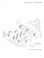
2-C YCLE ENGINE FUNDAMENTALS
The Rockwell 2-cycle air-coo led ga soline engine,
pa rti cu larly th e axial fan -cooled twin cy lin der
e n gi n e, ha s become v ery popular today for
snowmobil es. It i s uniquely qualified for this application because of its high power output, li g ht
weight and ease of lubri catio n, with fewe r
moving parts than other conventional 2-cycl e
and 4-cycle e ngin es.
IN TAKE
Howe v e r, in order to get the best possible u se
and ensure that it r e tain s its high degree of
d ependab ility and e ndurance, it must receive
proper care and maintenance. Th erefo re, it i s
necess ary for u s t o know some thing about the
basic fundam enta ls of this e ngin e and how it
functions.
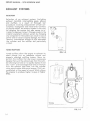
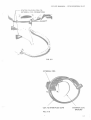
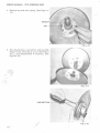
OPERATION
The Rockwell 2-cycle Twin Cylind e r e ngine is of
th e loop-scave nged third port type, the most
widely used design today. It u ses a mixture of
gasoline, oil and air for combu stion, lubrication
and cooling . It fires on every stroke of each
piston. Th ere are two power strokes for every
revolution of th e crankshaft.
EXH/ UST
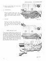
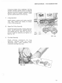
A s the piston moves upward in th e cylinder it
draws the fuel/air mixture into the crankcase
through the intake manifo ld whi le at the same
time compr ess ing fu e l that has b een forced into
the combustion chamber. See Fig. 1- 1A.
TRANSFER
As the piston nears top dead center the spark
plug is fired and the compressed fuel/air mixture burns and expands thereby forcing th e
pi ston downward on a power stroke.
As the downward stroke of the piston turn s th e
crankshaft, it al so start s to compress th e
fuel/air
mixture
in
the
crankcase
and,
simultaneously, ope ns th e exhaust port and
closes the intake port. See Figs. 1-1 B & C.
C
'---- - -- - ----'
FIG. 1- 1
n
1·2
SERVICE MANUAL - 1975 SCORPION WHIP
After the exhaust port is fully open and the in take port is fully closed, further piston travel
starts to open the transfer ports. The com pressed fuel/air mixture from the crankcase
then travels up the transfer ports and into the
combustion area.
After m ost of th e burned ex haust gases have
left the cy linder, an incoming charge of fuel/air
mixture scavenges the combustion area g iving it
a fresh charge and the cycle is then repeated.
See Fig. 1-1 D.
Because lubrication is dependent on the m 1xmg
of o il and fuel, it is extremely important that
good quality o il and gaso lin e are properly
mixed . The proper ratio of oi l to gasol ine w ill
prevent possib le engine overheating, piston or
cy lin der scoring, or eventua l engine seizure.
Too much oil an d not enough qasoline can lead
to incomplete combustion, fouled plugs, carbon
bui ld-up and muff ler clogging.
(
1-3
SERVICE MANUAL - 1975 SCORPION WHIP
EXHAUST SYSTEMS
l
SELECTION
Selection of an exhaust sy s tem (including
exhaust manifold, interm e diate pipes, e lbows
and muffler), is a r es ult of thorough te st
procedures involving m e asurem e nt of fu e l con sumption, horsepow e r and noise level. Contrary
to popular belief, the exhaust system is not only
for quieting the engine, but al so se rve s to in crease horsepower output. Changes mad e to the
original equipm e nt exhaust system by changing
any component in th e sy stem can result in loss of
power and/or severe e ngin e damage. For thes e
r e a sons, inte rmediate le ngth s of pipe betweeen
the cylinder and th e muffler are particularly
critical.
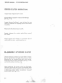
Do naldso n
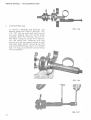
TUNED MUFFLERS
FIG. 1-2
Tun e d mufflers allow the engine to exhaust its
spent charge into an adequate volume and
properly matched muffling system. More important, the mufflers that are tuned, incorporate
designs that suck the exhaust gas from the cylinder a l lowing fuel and air to rapidly replace it and
a lso "cram" over -sc avenged fu e l and air mixture
fr o m the e xhaust pipe back into the cylinder
u si ng sound waves and sound energy. This is ac complished at the speed of sound which allow s
the engine to produce h igher torque at higher
RPMs.
(
Tuning
Co u r tesy o f Dona ld son Muf fl er Co
FIG. 1-3
1-4
SERVICE MANUAL - 1975 SCORPION WHIP
DESCRIPTION
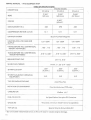
TABLE OF SPECIFICATIONS
ENGINE MODEL
2F 400-8
2F-340-6
2.362"
(60 mm)
BORE
2F 440-9
2.559"
( 65.0mm)
2.658 "
(67.5mm)
-
2.362"
(60mm)
STROKE
DISPLACEMENT IN cc
338
398
428
COMPRESSION RATION (actual)
1 2: 1
1 2: 1
12:1
IGNITION SYSTEM
LIGHTING COIL VOLT AGE AND
OUTPUT
Bosch Flywheel Magneto
12V-150W
12V 150W
12V 150W
*TIMING BEFORE TDC (CENTRIFUGAL
WEIGHT ADVANCED)
. 102 - . 1 1 2
. 102- . 112
. 102 - . 1 1 2
TIMING BEFORE TDC (CENTRIFUGAL
WEIGHT RETARDED)
.0 18" to .020"
.018" to .020"
BREAKER POINT GAP
.014"to.016"
SPARK PLUG THREAD
14mm. x 1.25- 3 / 4 " reach
SPARK PLUG GAP
SPARK PLUG-BOSCH (ORIGINAL
EQUIPMENT)
TYPE OF ENGINE COOLING
ROTATION OF CRANKSHAFT
CARBURETOR
FUEL/OIL RATIO
GASOLINE
TYPE OF OIL
.020"
(0.5mm.)
N -3
.020"
(0.5mm.)
.020 "
(0. 5mm .)
N-3
N-3
Axial Flow Fan
Counterclockwise (PTO side)
.
Walbro W F
As Specified on Scorpion Oil Container
95 octane, minimum (lead free not acceptable)
Specia l 2-Cycle Snowmobile Oil
* Do not exceed indicated advance, as this will result in severe engme damage.
l -6
.0 18" to .0 20"
SERVICE MANUAL - 1975 SCORPION WHIP
TABLE OF SPECIFICATIONS
340-6
TORQUE SPECIFICATIONS
CYLINDER HEAD NUTS
440-9
400-8
28 -32 Ft .-Lb.
16-1 8 Ft. - Lbs.
CYLINDER BASE NUTS
16-18Ft.-Lbs.
FLYWHEEL NUT
44-50 Ft. - Lbs.
INTAK E MANIFOLD NUTS
16-18 Ft. - Lbs.
FAN HOUSING SCREWS
16-18Ft.-Lbs.
FAN WHEEL NUT
22-24 Ft.- Lbs.
RING GEAR SCREWS (6mm.)
6-7Ft.- Lbs .
RING GEAR SCREWS (8mm.)
10- 12Ft.-Lbs.
Tightening Sequence for Cylinder Base Nuts
All Models
(
PTO SIDE
0
0
8
8
0
0
0
8
Tightening Sequence for:
Cylinder Head Nuts, Fan Housing, Ring Gear Flange, Intake Manifold
and Recoil Starter Clamps
0
0
0
340-6
(
8
0
400-8
440-9
0
®
0
0
CD
1-7
SERVICE MANUAL- 1975 SCORPION WHIP
ROCKWELL TWIN CYLINDER ENGINES
MODELS 2F-400-8
(
2F-440-9
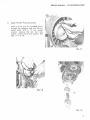
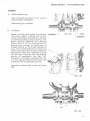
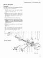
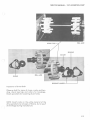
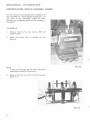
DISASSEMBLY
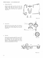
A.
Recoil Starter
Remove four (4) screws holding the
recoil assembly to the fan housing.
See Fig. l -4.
See pages l-28 A, B, C for recoil starter
disassembly.
FIG. 1-4
)
B.
Lower Fan Pulley and Carrier Assembly
FIG. 1-5
Remove the three (3) hex head bolts on
the carrier. Remove carrier, lower pulley
assembly and V -belt. See Figs. 1-5, 1-6.
)
FIG. 1-6
l -8
SERVICE MANUAL - 1975 SCORPION WHIP
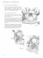
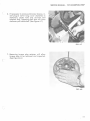
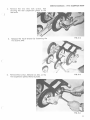
C.
Upper Fan Belt Pulley Assembly.
Insert a 3/16" drill or a suitable punch
through the indexing hole into the im-·
peller body. With a 17 mm socket
wrench, remove the fan nut, lock
washer, pulley halves and spacers. See
Figs.1-7, 1-8,1-9.
FIG. 1-7
(
FIG. 1-8
FIG . 1-9
l -9
SERVICE MANUAL - 1975 SCORPION WHIP
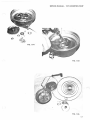
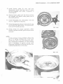
D.
Flywheel Magneto
Remove the crankshaft nut using a 27
mm socket wrench. Pull the flywheel by
attaching flywheel puller 444-31-843-2 to
the flywheel flange using bolts provided.
Screw the three bolts through the puller
into the flange and tighten evenly. With
a socket wrench, tighten the puller bolt
until the flywheel loosens on the
crankshaft. See Figs. 1-10, 1-11, 1-12, 113.
FIG. 1-10
)
FIG. 1-11
FIG. 1-12
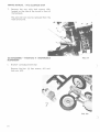
NOTE: It is important that care is taken
to remove the positioning key in crank shaft before attempting to remove the
flywheel assembly. Failure to do this
could result in damage to advance
mechanism.
FIG. 1-13
l-10
SERVICE MANUAL - 1975 SCORPIO N W HIP
E.
Intake Manifold Assembly
Remove t he four (4) intake manifo ld
nuts and washers. Remove manifold
assembly and insulators. See Figs. 1- 14,
1-1 5.
FIG. 1-14
)
FIG. 1- 15
] . ]]
SERVICE MANUAL - 1975 SCORPION WHIP
F.
Fan Housing and Armature Plate Assemb ly
(
Re m o ve screw ho ld ing spark plug wire
bracket t o fan housing. With a socket type 5
mm Allen wrench and impact driver, r e move
th e four (4) mounting bolts holding fan
housing to crankcase. (See Fig. 1- 16) .
Remove fan hou sing from cran kca se (See
Fig . 1- 17).
FIG. 1-16
(
Unplug connect or hou sing coil wire s. (Note
color coding of wires.) Re move armature
plate assembly and wire s, a s a unit, from
fan ho using.
FIG. 1-17
(
1-1 2
SERVICE MANUAL - 1975 SCORPION WHIP
r
Remove the fan by tapping the end of fan
shaft with a soft hammer. With a flat punch
and hammer, tap the inner race of the furthest bearing in the housing. See Figs. 1-18,
1-19, 1-20.
FIG. 1-18
(
FIG. 1- 19
(
'
FIG. 1-2 0
1- 13
SERVICE MANUAL - 1975 SCORPION WHIP
G . Re move spark plug s with spark plug
wrench. (See Fig. 1-2 1.)
H.
l
Cy linder Heads
Remove cylinder head nuts with a
13 mm socket wrench. Mark cy li nder
heads before removal from cy linder.
Remove and discard gaskets. See Fig.
1-22.
I.
Cy linders
FIG. 1-21
Remove the eig ht (8) cy linder base
nuts using a 13 mm socket wrench and
remove the eight (8) spring washers.
The cylinders may b e removed. See
Fig . 1-23.
'{_}
NOTE: I M P 0 R T A N T
If removal of cylinders only is required, care
must be taken that the crankcase seal is not
disturbed. The removal of the PTO cylinder
will allow the placement of two bolts and
nuts with flat washers to app ly constant pressure to crankcase assembly. Bolts should be
placed in the center two holes (adjacent to
the fan side cylinder). See Fi g. 1-31. The
second cylinder may now be removed.
,,
'\
''
~'
._ ;/
J"
FIG. 1-22
r )
f\G. 1-23
1- 14
SERVICE MANUAL - 1975 SCORPION WHIP
J.
Piston and Wri st Pin
With needle nose p liers, remove
pistons. Heat the piston with a
propane torch . Heat only to the
piston may still be held in hand.
out.
K.
circlips from
heat gun or
point where
Push the pin
To separate the crankcase halves, hold upper
portion of crankcase assemb ly in one hand,
lifting slightly and tap the end of the crankcase with a soft hammer. The crankcase wi ll
separate and the crankcase may be
removed. See Fig. 1-24.
~I
I
FIG. 1-24
l -15
SERVICE MANUAL- 1975 SCORPION WHIP
L.
Crankshaft Bearings
To remove crankshaft end bearings, use
bearing puller 444-31-807-0. See Figs. 1-25,
1-26, 1-27. Slip the puller half shells around
the outer bearing race and around puller
assembly. Slide the retaining ring over the
half shells. Using two (2) 27 mm wrenches,
turn the center bolt clockwise with one
wrench and use the second wrench to hold
the puller body. Before removing the PTO
side crankshaft bearing, insert a 1/2" 20 UNF
bolt, 1/2" long, to protect the internal thread
of the crankshaft.
FIG. 1-25
)
FIG. 1-26
/
FIG. 1-27
1-16
SERVICE MANUAL • 1975 SCORPION WHIP
ASSEMBLY
A.
Crankshaft Bearings.
Heat crankshaft bearing s in oi l (or oven) to
approximately 180 d eg rees .
Slide bearing on crankshaft.
B.
Crankcase.
Inspect and c lean both halves of crankcase.
The proper sealant material such as Permatex Hy-Tack Spray should be now sprayed
on crankcase sea ling surfaces. See Fig. 1-29.
Before installing crankshaft into crankcase
lower half of it will be necessary that all
bearing outer surfaces be wiped clean of
foreign material so that proper sealing will
occur. After installing PTO thrust washer and
oil sea l (inside groove of oil sea l coated with
light grease) place the crankshaft carefully
into the lower crankcase half and properly
position all components. See Figs. 1-30.
Placement of the upper crankcase half may
now be made . Be certain that the center sea l
i s lined up with the crankcase split lin e.
t
t t
FIG. 1-28
BEARING_j
I
L-SEAL
-BEARING
Tap upper crankcase half to seat with lower
half.
FIG. 1-29
-~
\
-
FIG. 1-30
1-17
SERVICE MANUAL - 1975 SCORPION WHIP
(
Install lwo crankcase holding bolts in the
center holes of the PTO side of crankcase.
(Fig. 1-31) Tighten finger tight.
C.
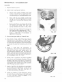
Piston, Cylinder and Cylinder Heads
FIG. 1-31
The pistons must be clean and free from carbon deposits and the piston rings must fit
freely in their grooves. Rings are marked for
proper side up. The arrow on the crown of
pistons must point toward exhaust side of
engine. Piston pins, needle bearings, check
plates and circlips may now be installed, according to the procedure below. (Always use
new circlips.) See Figs. 1-32, 1-33, 1-34, 1-
(
35.)
.:
'
'~
11
FIG. 1-32
CIRCLIP OPENING HERE---'
1- 18
FIG. 1-33
I
SERVICE MANUAL- 1975 SCORPION WHIP
1.
Oil the piston pin end bearings.
2.
Install one circlip in piston.
3.
Heat the piston sufficiently to allow pin to
push into piston and install pin.
4.
Install second circlip. (See Fig.
correct orientation of circlips.)
1-33 for
0
FIG. 1-34
(
FIG. 1-35
l-19
SERVICE MANUAL - 1975 SCORPION WHIP
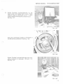
In sta ll base gaskets on th e cylinder studs and
position aga inst the cylinder flanges (see Fig.
1-36). With the use of a ring compressor,
lower cylinders one at a time over th e
pistons. Install base washers and nuts finger
tight. See Fig. 1-37, 1-38.
Temporari ly install the intake manifold
without gaskets and tighten manifo ld nuts to
sixteen (16) to eig hteen (18) foot pounds.
See Fig . 1-39. Cylinder base nuts may now be
torqued to sixteen (16) to eighteen (18) f oot
pounds as outlined on spec ification page.
The proper piston he ight can be measured at
the top of the cylinder. The edge of the crown
of the piston must not protrude above the top
of the cy l inder with the p i ston in th e top dead
cen t e r position. If the piston does protrude
above the cylinder, a thicker ba se gasket
must be used. See specifica tion page for
dimensions and color cod ing. It is important
that only one cylinder at a tim e be ad justed
or the crankcase will separate and lose it's
seal.
~
l
FIG. 1-36
FIG. 1-37
I
FIG. 1-38
1-20
SERVICE MANUAL- 1975 SCORPION WHIP
Oil cy lind ers and pistons before installing
cylinder heads. Install head gaskets with the
wide side of inner metal flange of the
gaskets up toward the cylinder heads.
Torque cylinder head nuts to sixteen (16) to
eighteen ( 18) foot pounds. (See Fig. 1-40).
NOTE: The head gasket for th e 400 cc engine
has an additional hole in it to distinquish it from the 440 cc gasket.
(
FIG. 1-39
FIG. 1-40
l -2 1
SERVICE MANUAL - 1975 SCORPION WHIP
D.
Fan Housing and Impeller Bearings
r
Clean fan shaft hub. Install circlips and
spacer. Use grease to hold spacer in place.
Pack bearings in medium grease into
housing with sealed surface outward. See
Figs. 1-19, 1-20. Install fan and shaft.
E.
J
Fan Housing and Armature Plate.
l
Install new seal in fan housing. Lubricate the
inner groove of the oil seal with a light
grease. See Fig. 1-41.
i
1
Install new o-ring and apply sealant material
around o-ring surface (see Fig. 1-41 ). Install
the armature plate wires through hole in fan
housing and install armature plate with hold
down screws, washers, and lockwashers. See
Fig. 1-42.
Place fan housing assembly over crankshaft
and position to crankcase assembly . Install
the four Allen head screws and lockwashers
and tighten evenly until fan housing is
against crankcase assembly. See Fig. 1-43.
FIG. 1-41
)
'
FIG. 1-42
(
FIG. 1-43
l -22
SERVICE MANUAL· 1975 SCORPION WHIP
Torque to sixteen (16) to eighteen (18) foot
pounds. Connect ignition wires to external
ignition coil and to connector housing. Check
ground wires for proper position. Install
ignition cable bracket to fan housing.
F.
Intake Manifold
Install spacers, gaskets and intake manifold
(Fig. 1-44) . Torqu e nuts evenly to sixteen
( 16) to ( 18) foot pounds.
G.
Upper Fan Pulley As sembly
Install the tapered washer. Install pulley half,
shims, second pulley half, tapered washer,
lock washer and nut. Use 3/16" drill bit or
punch to hold fan assembly and tighten nut.
See Fig. 1-45.
~
~
oo
\!>·~''
00
FIG. 1-44
H.
Flywheel Assembly
Check advance mechanism for free
operation, lubricate inside cam surface
(Grooved area). Slide assembly over
crankshaft and align key ways.
)
1-23
SERVICE MANUAL - 1975 SCORPION WHIP
Instal l key, lockwasher and nut in that order.
Tighten securely. See Fig. 1-46. Follow
Timing Procedure Section as next step.
I.
lower Fan Pulley Assembly
FIG. 1-46
Install pulley half, belt, second pulley half,
recoil carrier, lockwashers and bolts evenly
while rotating crankshaft. The proper belt
deflection should be 1/8" on each side.
Proper adjustment can be made by add ing or
removing shims between upper pulley
halves. See Fig. 1-47.
J.
Recoil Starter
FIG. 1-47
Install the recoil starter assembly and tighten
securely. See Fig. 1-48.
...... ....~
__.
FIG. 1-48
l-2 4
SERVICE MANUAL- 1975 SCORPION WHIP
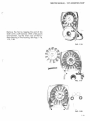
RECOIL STARTER
Disassembly
(See Fig. 1-49 for recoil start breakdown, and Fig.
1-50 for Recoil Starter Assembly.)
1. Remove retaining nut (11), spring washer
(12) and Thrust washer (8) from threaded
shaft of reel hub. (Fig. 1-51).
2. Manipulate friction plate (4) on reel hub until
eye end of return spring (9) aligns with
retaining slot. Remove friction plate. (Fig. 152, 1-53).
3. Remove the three pawls (3), (Fig. 1-54) .
4. Remove return spring (9), spring (6) and cup
washer (7). Fig. 1-53. Note position of plain
end of return spring in the spring retaining
hole in reel hub.
5. Unwind the rope; lift and untie the knotted
end from center hub of reel, remove reel (2).
(Fig. 1-55).
6. Lift long rolled end of main spring (5) from
the fixed spring retaining pin in the case and
carefully remove the spring (Fig. 1-56).
12
8 21 4
9
6
7
3
2
10
18
19
20
Recoi I Starter
14
3
14
13
3
5
FIG. 1-49
l -25
SERVICE MANUAL - 1975 SCORPION WHIP
7. Clean all parts, except rope, using a suitable
cleaning solvent. If rope requires cleaning,
wash it in a solution of soap and water.
Thoroughly dry all parts after cleaning.
(
8. Inspect all parts for obvious damage and
wear.
FIG. 1-50
(
)
\
I
FIG. 1-51
FIG. 1-52
Q "'_,
( ) ,, ·, .!'.
f) "
FIG. 1-53
l-26
SERVICE MANUAL - 1975 SCORPION WHIP
~
l -
FIG. 1-54
FIG. 1-55
)
FIG. 1-56
1-27
SERVICE MANUAL - 1975 SCORPION WHIP
Assembly
1. Replace defective parts.
2 . Install main spring as follows:
a.
Secure main spring winding tool, part
number 43-0797-60, or equ ivalent tool,
circular end up, in a suitable bench vise.
b.
Start with the long rolled end of main
spring (5) and wind spri ng into circular
end of tool in a clockwi se direction. (Fig.
1-57)
0
c.
Remove tool from vi se. Grasp the tool by
its handle and lower th e tool , with
spring in stalled, into case (1) (Fig . 1-58).
d.
Secure the long roll ed end of spring over
the fixe d spring retaining pin . (Fig . 159). Remove winding tool (Fig. 1-60) .
Apply a light film of Lubriplate, or
equivalent, to spring.
FIG. 1-57
3. Secure case, open side up, in bench vise.
4. Tie a knot at one end of the rope . Secure
knotted e nd in th e center of reel (2) . Pull
rope taut and wind e ntire rope around reel in
an anti-clockwise dire ction until th e free end
protrudes through the notched section of the
reel.
5. Apply a light film of Lubriplate, or
equivalent, to center hub of case and install
the reel. Push down and rotate reel in an
anti-clockwise direction until the hook engages with the free end of main spring. Ten sion will be felt when reel and spring are properly engaged. (Fig. 1-61, 1-62).
(
FIG. 1-58
6. Rotate reel a maximum of three com plete
turns in an anti-clockwise direction. Do not
exceed three turns; hold reel in this position
and feed free end of rope through case at the
rope guide hole. Install rope guide. Loosely
knot the rope to prevent recoil.
7 . Apply a light film of Lubriplate or equivalent
to pawls (6) and install them on the reel in
the pawl retainers. (Fig. 1-63). (See Fig. 1-49
for part identification numbers.)
8. Install cup washer (7) flat side down, spring
(6) and return spring. Ensure that plain end
of return spring is properly engaged in the
retaining hole in reel hub.
1-28
FIG. 1-59
SERVICE MANUAL · 1975 SCORPION WHIP
(
9. Install friction plate (5) over reel hub.
Manipulate plate until eye end of return
spring engages and locks crosswise in
retaining slot.
10. Rotate friction plate unti I the three notches
are aligned with pawls when pawls are at
the recoil position.
11. Install flatwasher (8). lockwasher (12) and
nut (11 ). Tighten nut securely.
12. Untie the temporary knot in free end of rope
and install the rope handle. Tie a permanent
knot and fit handle securely.
FIG. 1-60
13. Check starter for proper operation. When
handle is pulled outward, pawls should move
outward.
(
NOTE:
If main spring is to be installed without the
use of a spring winding tool, wind main
spring into case in an anti-clockwise direction. Clockwise installation on the winding
tool is necessary to ensure correct anticlockwise installation of the spring when tool
is placed upside down in the case.
FIG. 1·61
FIG. 1·62
(
FIG. 1·63
l-29
SERVICE MANUAL - 1975 SCORPION WHIP
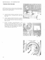
TIMING PROCEDURE
NOTE: Recoil starter, carrier, lower pulley assembly and spark plugs should be removed before
beginning timing procedure.
A.
Install the dial indicator assembly into spark
plug hole of No. 1 cylinder (P.T.O. side). See
Fig. 1-64.
B.
Attach negative lead of ohmmeter to engine
ground. Attach positive lead of ohmmeter to
No. 1 cylinder terminal in connector housing.
See Fig. 1-65.
C.
FIG. 1-64
Rotate
flywheel
counterclockwise
until
points are on the high side of cam on No. 1
cylinder. Points are at maximum open position observed through opening in flywheel.
Check gap with wire gauge and adjust to
.015 if necessary. See Fig. 1-66.
)
FIG. 1-65
)
FIG. 1-66
1-30
SERVICE MANUAL· 1975 SCORPION W HIP
D.
Rotate flywheel
dead center and
selector knob on
meter needle will
See Fig. 1-67.
counterc lockwise to top
adjust dial to zero. Place
ohmmeter to R x 1. Ohmindicate a closed circuit.
FIG. 1-67
Move the centrifugal weights in flywheel to
the full advanced position. See Fig. 1-68.
I
I
I
i
}
FIG. 1-68
Rotate flywheel counterclockwise one complete revolution to between .1 02 and . 112.
See Fig. 1-69.
FIG. 1-69
l-31
SERVICE MANUAL· 1975 SCORPION WHIP
At this point the breaker points for No. 1
cylinder should open. (Break contact) This
will show on the ohmmeter. Needle will
move to the left. If this does not occur, the armature plate needs adjusting. This is accomplished by loosening the hold -down
screws and turning plate either left or right
while observing needle action. With proper
positioning, needle should move to left with
slight movement of armature plate and
flicker back with opposite plate movement.
Tighten hold-down screws securely. Re-check
procedure. See Fig. 1-70.
NOTE:
In Fig. 1-70 flywheel has been removed for
clarity of illustration.
FIG. 1-70
(
E.
Remove dial indicator assembly and install in
No.2 cylinder (fan side). See Fig. 1-71.
Attach positive lead of ohmmeter to No. 2
cylinder terminal in connector housing.
Rotate flywheel counterclockwise to top
dead center. Set dial indicator to zero. Again
move centrifugal weights in flywheel to full
advanced position. Rotate flywheel counterclockwise while watching dial indicator.
The needle must make one full revolution
and stop at between .1 02 and .112. At this
point, needle should move to left indicating
point contact (closed). If this does not occur,
points need slight adjustment. Re-check
procedure.
FIG. 1-71
(
1-32
SERVICE MANUAL - 1975 SCORPION WHIP
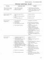
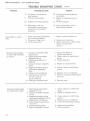
TROUBLE SHOOTING CHART
(
TROUBLE
Manual starter rope
comes out but pawls
don't engage.
PROBABLE CAUSE
1. Lack of friction plate
2.
return spring action.
Defective pawls.
REMEDY
1. Check friction plate returnspring. Replace as required.
2. Check for broken or bent
pawls. Replace pawls as required.
Manual starter rope
doesn 't return.
Electric starter
inoperative.
1. Recoil spring broken or
3. Replace pulley.
1. Loose electrical
1. Retighten connections.
connections.
2. Poor ground.
3. Faulty battery or circuits.
4. Faulty electric starter.
(
Hard to start or
won't start.
1. Inoperative diaphragm or
2.
inlet check valve.
Fuel enrichening valve not
not pulled up to start.
3. Spark plugs improperly
gapped, dirty or broken.
4. Magneto breaker points
improperly gapped or dirty.
5. Head gasket blown or leaking.
6. Empty gas tank or improper
fuel mixture.
7. Water in fuel system.
8. Weak coil or condenser .
9. Obstructed fuel system .
(
1. Replace spring.
bent.
2. Pulley housing warped or
bent.
3. Starting pulley worn.
2. Replace housing.
2. Secure ground connection.
3. Check, recharge or replace
battery.
4. Check starte r solenoid.
Repair or replace.
5. Inspect starter motor for
evidence of moisture and
broken or worn brushes. Dry
out as necessary.
6. Check starter switch . Replace
if required.
7. Check harness or connector
for broken wire. Repair or replace.
1. Refer to Carburetor
Section.
2. Ensure enrichening valve is
pulled up.
3. Remove plugs. Clean, adjust or
install new plugs.
4 . Clean, ad ju st or replace
points.
5. Replace gasket.
6. Refill tank with specified
fuel/oil mixture.
7. Drain fuel from carburetor.
Add carburetor de-icer as requi red to fuel.
8. Replace faulty coil or
condenser.
9. Disconnect fuel lines.- Clear
obstruction . Flush system. Connect fuel lines.
1-33
SERVICE MANUAL- 1975 SCORPION WHIP
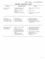
TROUBLE SHOOTING CHART
TROUBLE
12. Engine not timed properly.
13. Secondary wire not
connected or spark plug
protector not installed
properly.
Impossible to adjust
idle.
Mi ss ing at low speed
or won't idl e smoothly
or slowly.
1. Spark retarding mechanism
not working properly.
2. Pistons or rings worn.
3. Faulty carburetor.
1. Incorrect carburetor idle
2.
3.
4.
5.
6.
7.
8.
Missin g at high speed
or intermitten t spar k.
adjustment.
Spark plugs improperly
gapped or dirty.
Head gasket blown or
lea king .
Loose or broken magneto
wires.
Magneto brea ker points
improperly gapped or
dirty.
Weak coil or condens er.
Improper fu e l mixture.
(1) Too much oil
(2) Too littl e oil
Lea king cra nk shaft seal.
1. Spark plug s imprope rly
2.
3.
4.
5.
6.
7.
1-34
REMEDY
PROBABLE CAUSE
10. Air leak in crankcase or
inlet system.
1 1. Primary wire broken.
gapped or dirty .
Loose or broken magneto
wires.
Magn e to brea ker points
imprope rly ga pped or dirty.
W ea k coil or condenser.
Hea t rang e of spark plug
incorrect.
Leaking h ead gasket.
Engine improperly timed.
(coNr.)
)
10. Check crankcase pressure
(3-6 PSIG)
11. Repair or replace primary
wire.
12. Re-time engine.
13. Secure secondary wire or
spark plug protector.
1. Repair retard mechanism.
2. Replace as necessary.
3. Check carburetor, check valve.
Refer to Carburetor
Section.
1. Adjust idle-Refer to
Carburetor Section.
Clean,
adjust or install new
2.
plugs.
3. Replace gasket.
)
4. Repair or replace wires.
5. Adjust, clean or install new
points.
6. Replace coil or condenser.
7. Refuel, using specified fuel/oil
mixture.
8. Replace seal.
1. Clean, adjust or install new
plugs.
2. Repair or replace wires.
3. Clean, adjust or install new
points.
4. Replace coil or condenser.
5. Install specified spark plugs.
6. Replace head gasket.
7. Re -time engine.
)
SERVICE MANUAL- 1975 SCORPION WHIP
TROUBLE SHOOTING CHART
)
TROUBLE
REMEDY
PROBABLE CAUSE
Coughs, spi t s, slows
down, surges
1. Idle or high speed jets too
1. to 5.
lean .
Adjust carburetor. Refer
2. Leaking gasket flange.
Carburetor Section.
3 . Inlet control level set too
low .
4. Pulsation line obstructed.
5. Fuel pump not supplying
enough fuel due to :
( 1) Punctured diaphragm.
(2) Inoperative inlet check
6. Reseal crankcase.
valve.
6. Crankcase not properly
7. Refer to Carburetor
sealed.
Section.
7. Idl e or main carburetor
8. Remove fuel lin e. Clear
nozzle obstructed.
obstruction. Replace line.
8. Fuel line obstructed.
9. Refer to Carburetor
Section.
9. Carburetor inlet needle and
seat obstructed.
Overheating
1. Carburetor too lean.
2. Carburetor too rich.
3. In correct timing.
4. Too much carbon.
5. Spark plug too hot.
6. Engine fan belt loose or
to
1. and 2. Adjust carburetor.
Refer to Carburetor Section .
3. Retime engine to Specifications.
4. Remove cylinder heads. Clean
top of pistons and inside
compression chamber. Clean
out exhaust port.
5. Install specified spark plugs .
6. Replace or adjust.
broken .
7. Air lea k in manifold.
7. Tighten nuts or change
8. Crankcase seal lea king.
8. Fit new seal.
1. Idle need le or high speed
carburetor jet too rich.
2. Enrichening valve not operating properly (bent linkage).
3. Float leve r too high . (carburetor floods).
4. Air bleed plugged.
5 . Muffl e r obstructed.
6 . Engine not secured tightly
to e ngin e support.
7 . Water in gas.
1 to 4. Adjust needle or change
jet. Refer to Carburetor Section.
gaskets.
Vibrates excessively
or runs rough and
smokes.
5. Check and dear muffler.
6. Tighten engine mounting
bolts.
7. Add carburetor de-ice fluid
as required.
1-3 5
SERVICE MANUAL · 1975 SCORPION WHIP
TROUBLE SHOOTING CHART
PROBABLE CAUSE
REMEDY
1. Spark plug wires reversed.
2. Flywheel key missing or
sheared.
3. Faulty condenser.
4. Improper timing.
5. Faulty breaker points.
6. Unhooked spark retarding
mechanism- or spring
broken .
l. Install wi're correctly.
3.
4.
5.
6.
1. Spark plugs improperly
1. Clean, adjust or install new
gapped or dirty.
2. Magneto breaker points
improperly gapped or
dirty.
3. Faulty coil or condenser.
4. Loose or broken magneto
wires.
5. Blown head gasket.
6. Float lever adjustment too
high.
7. Crankcase leaking.
8. Main (high speed) jet t0o rich.
plugs.
2. Clean, adjust or install new
points.
wires.
5. Replace head gasket.
6. Refer to
Carburetor Section.
7. Install new seal.
8. Change jet.
1. Leaking cylinder head.
1. Check head for warps, cracks.
TROUBLE
Won't start, kicks back
and backfires.
No acceleration, low
top R.P .M., hard to
start.
Good spark but
engine runs on one
cylinder.
2. Replace key.
Replace condenser.
Re-time engine.
Adjust or replace points.
Reconnect mechanism or
replace spring.
3. Replace coil or condenser .
4. Repair or replace magneto
Install new gaske t and
cylinder head.
2. Repair or replace wires.
2. Magneto wires broken
inside (coil ground
broken).
3. Cracked cylinder wall.
4. Defective spark plug.
3. Replace faulty cylinder.
4. Clean, adju.;t or install new
5. Breaker points improperly
5. Re-adjust points.
plug.
gapped.
No acceleration. Idles
well but dies down
when put to full
throttle.
6. Crankcase seal leaking.
6. Install new seal.
1. Low speed needle set too
1. to 6.
2.
3.
4.
5.
6.
7.
lean.
Dirt behind needle and seat.
High speed jet obstructed.
Float lever set too low.
Silencer obstructed.
Fuel pump not supplying
enough fuel due to:
(1) Punctured diaphragm
(2) Non-functioning check
valves.
Fuel line obstructed.
Adjust carburetor.
Refer to Carburetor
Section.
7. Remove fuel line. Clear
obstruction . Replace line.
8. Not enough oil in gas.
9. Breaker points improperly
gapped or dirty.
10. Engine improperly timed.
1-36
(
8. Refuel, using specified fuel / oil
mixture.
9 . Adjust, clean or install new
points.
10. Re-time engine to specifications.
(
SERVICE MANUAL - 1975 SCORPION WHIP
TRO·UBLE SHOOTING CHART
TROUBLE
No power under
heavy load.
REMEDY
PROBABLE CAUSE
l. Magneto breaker points
improperly gapped or
dirty.
2. Ignition timing too far
advanced.
3. Magneto coil plate loo se.
l. Clean, adjust or install new
points.
2. Adjust timing.
3. Check magneto and secure
coil plate.
(
Cranks over
extremely easy on
one or both cylinders.
Loss of compression.
1.
2.
3.
4.
Engine won't crank
over. Unable to
rotat e flywheel.
l. Piston rusted to cylinder
2.
3.
4.
5.
Scored piston.
Blown head gasket.
Loo se spark plug.
Head bolts not tight.
wall.
Crankshaft seized to
bearing . (main or rod)
Broken connecting rod.
Flywheel seized t o coil
plate.
Engine improperly
assembled after repair.
1.
2.
3.
4.
Replace faulty piston.
Replace head gasket.
Check plug for security.
Torque head bolts to proper
specifications.
l. Remove piston and cylinder.
Replace defective parts .
2. & 3. Disassemble engine.
Replace defective parts.
4. Remove flywheel. Replace
defective parts.
5. Recheck re-assembly
procedure .
(
l -37
'
J
: )
I
I
1975
Scorpion
. Whip
(
Service Manual
Carburetor
Section
2- 1
SERVICE MANUAL - 1975 SCORPION WHIP
Functional Description:
General:
The purposes of the carburetor are (1) to provide the amount of fuel that the engine needs in
operation and (2) to properly mix the fuel with air so that it will vaporize.
Pulsations, from the engine crankcase through the impulse line, actuate the carburetor
fuel pump to move the fuel from the fuel tank into the carburetor. The fuel level in the car buretor fuel reservoir is maintained by a float-controlled needle valve that opens as the
level drops and closes as the fuel rises to a specific level. The engine fuel demand determines the air flow through the carburetor throttle bore. The air flow rate varies the
pressure differential on the fuel in the reservoir. This pressure differential forces fuel into
the throttle bore through one or more openings depending upon the operational phase of
the engine.
(
)
_)
2-2
SERVICE MANUAL - 197 5 SCORPION WHIP
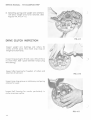
The function of each element of the carburetor is described below. (See Fig. 2-1 ).
1. Engine Impulse: Actuates fuel' pump diaphragm with alternating pressurevacuum pulses from engine revolutions.
2. Fuel Pump Diaphragm: Fluctuates in response to engine impulse. Draws
fuel into surge chamber with upward, vacuum stroke, of engine piston .
Pushes fuel with pressure downward stroke of engine piston, through
outlet check valve.
3. Fuel Inlet Fitting: Fuel drawn through line from tank .
4. Fuel Channel: Fuel is routed into surge chamber.
5. Surge Chamber: Fuel accumulates waiting for inlet check valve to open for
passage a t engine piston down stroke.
6. Surge Diaphragm: Reciprocates with pump diaphragm balancing to atmospheric pressure, cushions pulsations.
7. Leaf Spring: Assists pump diaphragm when engine impulses are weak at
starting and idle c ircui t s.
8. Inlet Check Valve: When opened by engine vacuum, allows fuel passag'e
from surge chamber into pump chamber, feeding to outlet check valve.
)
9. Outlet Check Valve: Opened by engine pressure pulse forcing fuel down
through inl et valve needle passage.
10. Fuel Channel: Routes fuel to inlet needle valve.
11. Filter Screen: Fuel is filtered before fed into inlet needle valve. Cleanse
screen when servicing by flushing or air stream.
12. Inlet Valve Seat: Hole through which fuel feeds when needle valve drops
s lightly away.
13. Inlet Needle Valve: As float rises it pushes valve into seat closing off fuel
passage. When float drops, needle opens hole in seat allowing fuel to flow
into bowl reservoir.
14. Lever: Raises and lowers with float to activate inlet needle valve .
15. Float: Raises and lowers to maintain fuel level as fuel is used.
16. Fuel Bowl Reservoir: Constant level of fuel stored and maintained by float
action on lever to open and close inlet needle valve.
2-3
SERVICE MANUAL - 1975 SCORPION WHIP
The four operationa l phases of the Walbro Float Carburetor used on the 1975 Whip are:
( 1) Starting operation
(2) Idle operation
(3) Part-throttle operation
(4) Full-throttle operation
Detailed performance of the carburetor in each of the four phases is described below.
Figures 2-1 through 2-4 are schematic diagrams and as such are accurate, functional
representations of the carburetor, but in some features deviate from actual physical appearance.
Sta rting Circuit
FIG. 2- 1
COLOR
2-4
CODE
A.
Enrichment Valve: : In operation when
control lever, is up (vertical). elimates
choke. Like opening a faucet an extra
column of fuel is introduced through
the valve into carburetor bore as
engine is cranked; offering easier,
quicker starts. This valve may be left
open until engine is warm.
B.
Throttle Valve: Must be at idle position
freeing both hands for starting. Required
air is drawn in through the air bleed
ports mixing with the fuel.
C.
Start & Idle Fuel Feed Tube: Fuel is
drawn by engine vacuum up tube,
through part throttle passage into
Enrichment Valve and id le circuit.
D.
Enrich ener & Idle Feed Ports: Tube picks
up at these two pockets for starting full
vo lume.
E.
Air Bleeds: Vacuum draws in air at these
four points to mix with fuel in metered
ratio.
F.
Enrichener Port: Fuel and air mixture
flows into throttle bore when enrichener
valve i s open .
G.
Idle Needl e: Fuel is a lso drawn through
the idle needle circuit which is pre-set
for the idle position.
H.
Idle !Feed Hole: Additional fuel is
dischar~ed f rom th i s port into th rottle
bore for starting.
Air
Crankcase
Impulse Air
SERVICE MANUAL · 1975 SCORPION WHIP
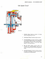
Idle Speed Circuit
c
FIG. 2-2
1.
Throttle Va lve: Remains closed, air being
drawn t hrough Idle Air Vent.
2.
Enrichment Valve: Closed as engine warms.
3.
Fuel Idle Needle: As engine requires, needle
is turned in to lean mixture or turned out to
a llow great e r fuel flow (like a water f aucet) .
During break-in, open l 1/2 t urns then close
about 1/2 turn a fter break-i n.
4.
Idle Air Vent: Engine vacu um draws ai r
through thi s interchangeable fix ed jet as
we ll as through th e part thrott le progress ion
holes.
5.
Fuel Idle Passage: Al l fuel f or id ling is drawn
through this passage. The fl ow can b e adju sted by th e Fue l Id l e N eedle.
2-5
SERVICE MANUAl. - 1975 SCORPION WHIP
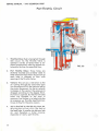
Par Throttl
1.
Throttle Valve: Fuel i s being f ed th rough
id le circui t . As th e Throttle Va lve is
opened a series of three holes is exposed progressively offering smooth acce leration as they increase fuel f low.
2.
Part Throttle Holes: Three ho les are
sk illfully located and carefu lly sized to
feed measured fue l drawn by vacuum as
each hole i s allowed to flow with
open ing of the Th rott le Va lve.
3.
Venturi: Thi s acts as a restricti o n to the
air rushing th rough the carbu r e t o r bore
into the engine to fil l th e vacuum left by
the piston movem ent. As th e air velocity
increases at the ven turi the pressure is
dropped according to the d egree Throt tle Va l ve is opened. As t he Part Throttle
holes are ex posed to the drop in
pressure, fuel rush es in t o help bring the
air pressure u p . The Idle Feed h o le continues to f low for th e same reaso n .
4.
Air i s also fed by th e Idle Air Ve1111i Jet,
a ffecting the vacu um w h ich lifts fu e l up
the feed t ube. A smaller jet del ivers less
a i r, and therefore a richer m ixture,
especially at "early" part throttle.
2-6
FIG. 2-3
SERVICE MANUAL · 1975 SCORPION WHIP
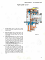
High Speed Circuit
1.
Throttle Valve: Valve is wide open to allow
full air and fuel flow, metered to contro l top
engine speed.
2.
Main Fuel Nozzle: As the throttle opens, air
velocity increases through the venturi and
the resultant vacuum draws fuel from the
main nozzle.
3.
FIG. 2·4
High Speed Fixed Jet: Fuel is fed to the fixed
jet hole from the bow l reservoir. The hole
may be varied in size by exchanging the jet
on which sizes are stamped. Larger engines
require larger jet holes for greater fuel consumption. Too large creates a rich mixture,
too small a dangerous lean mixture.
Note: High altitudes require a smaller jet
to compensate for the thinner air.
Note: Air Intake Silencer: Regulations require the noise created by air rushing into
the carburetor be reduced to a minimum. All
WF models are finely calibrated in tune with
original equipment Silencers, both Intake
and Exhaust. Anytime the characteristics of
either are changed or removed a risk of
burning out an engine exists and Warranty is
void .
2-7
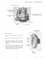
Carburetor Disassemb~y
Fuel Pump and Gaskets
1.
(
Remove four (4) mounting screws. (See
FIG.2-5). _ ·•
, .. · , .
.""'1-
-
.;.~:~
.----MOUNTING SCREWS (4}
~
WF- 10
340
Lay out part~ i Q.§~~~:~:~n<;~ shGwn in FIG .
2-6. Do not· remove nJbber ' fuel pump
valve~
unl·ess , replacements
are
, ., , available. . . , •.. ' ··, .
2.
~'
.~
~;.;>
3.
WF-11
400,440
Inspect all parts, opE}nmgs, needles,
valves, valve seats and,•iany oth~r functioning part Jor ,cloggj'ng or qamage.
(See Fig. 2-7) . ~
· ·•
4.
Clean port s with a mild so lvent or
regular fuel mixture. Repair or re:place
.'::~"parts as n'e cessary.
FIG. 2-5
HIGH SPEED FUEL JET
FUEL
INLET
)
_
til
J
G
D
FIG. 2-6
C
..
E
F
B
A
A.
Fuel pump cover assembly
B.
Fuel pump leaf spring
c.
Pump gasket
D.
Pump diaphragm
E.
Fue l pump body assembly
F.
Surge chamber diaphragm
G.
Surge chamber gasket
H.
Throttle bracket plate
I.
Fuel pump to body gasket
J.
Idl e Fuel feed tube
(Also see FIG . 2-13)
Carburetor body assembly
with float bowl assembly
K.
J
SERVICE MANUAL - 1975 SCORPION WHIP
(
~------------FUEL
PARTTHROTTLE-----'HOLES
CHANNEL-SURGE
CHAMBER TO NEEDLE VALVE
FIG. 2-7
ENRICHENER
PORT
FUEL ENRICHENER
VALVE LEVER
Fuel Bowl and Gasket
1.
Remove four (4) mounting screws. (See FIG.
2-8)
2.
Lay out parts sequentially as shown in FIG. 2-
9.
3.
Check all parts openings, valves, valve seats
and other functioning parts for clogging or
damage. Clean, repair and replace as
necessary.
4.
Clean parts with a mild solvent or regular
fu e l mixture. Clean all sediment from the
bottom of t'he bowl. Remove the main jet and
idle feed tube. Blow air through the idle feed
circuitry and main air bleed circuit.
FIG. 2-8
)
MOUNTING
SCREWS {4)
2-9
SERVICE MANUAL - 1975 SCORPION WHIP
MAIN AIR JET
Carburetor Reassembly
1.
Reassemble in reverse process of disassembly. Install components on top of the carburetor first
followed by the float bowl assembly.
2.
Specific care should be exercised in the following
areas:
a.
The fuel pump leaf spring should be flat to
center between the two castings when
seated.
b.
Care fully position the idle feed tube and tube
pressure spring.
c.
During installation, wind the float support
spring 1/2 turn from rest position for correct
loading. (See FIG. 2-1 0)
d.
Slide the fuel bowl gently over the point of
the idl e feed tube. A slight tension against
the tube pressure spring should be felt just
before the bowl se ats on its gasket.
FIG. 2-9
FUEL BOWL GASKET
FUEL BOWL ASSEMBLY
FLOAT SUPPORT
FLOATS
FIG. 2-10
FLOAT VALVE
LEVER
u
FIG. 2-11
2-10
SERVICE MANUAL - 1975 SCORPION WHIP
Adiustments
(
l.
IDLE FUEL - The idle needle (See FIG. 2-8)
is usually set one ( l) turn open. The setting will vary with operator preference
or changing conditions.
2.
HIGH SPEED FUEL - The fuel supply is
limited by a fixed high speed jet. (See
FIG. 2-6) The jets ore available in
various sizes and the optimum size used
will depend upon temperature, altitude,
etc. A smaller jet permits less fuel flow.
3.
FLOAT - With fuel bowl removed, and
float assembly in place, turn the body
costing upside-down so that float assembly is at top. Sight a long uppermost surface of float and adjust by bending
metering lever so that top surface of
float is 1 1/16" above body costing surface. (See FIG. 2-12) Adjustment may
also be accomplished using the special
tool available for this purpose. (See FIG.
2-13)
BEND THIS LEVER TO ADJUST
FLOAT HEIGHT IF NECESSARY.
t
1 1/16"
FIG. 2-12
( )
L
IDLE FUEL FEED TUBE
FLOAT ADJUSTMENT
(
GAUGE
J
FIG. 2-13
2-ll
I
)
( )
'-).
1975
Scorpion
Whip
Service Manual
Electrical
Section
~)
3-1
SERVICE MANUAL- 1975 SCORPION WHIP
ELECTRICAL SYSTEM
The Scorpion Whip Snowmobile
divided into four ( 4) subdivisions :
A.
B.
C.
D.
Electrical
System
is
LIGHTING COILS
Power Generation
Ignition
Voltage Regulation
Electrical Contro l and
Distri bution
POWER GENERATION
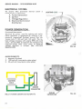
Functional Description:
Electrical AC power , used for lighting and tacho meter operation is generated by rotating a permanent ly magnetized flywheel around two stati onary coi Is ( 1-1 20 watt and 1-23 watt) . The noload vo ltage increases with engine RPM and could
reach 32 volts RMS. To maintain th e voltage at the
requi r ed system level (13- 14 vo lts). an external
vo ltage regulator is utilized . (See VOLTAGE
REG ULATIO N )
FIG. 3-2
MAIN ELEMENTS:
1.
2.
3.
Magnetic Flywheel
120 watt co il (mounted on stator plate)
23 watt coi l (mounted on stator plate)
FIG. 3- 1 POWER GENERATION SCHEMATk
3-2
-
EN G IN E
CO NN ECTOR
FIG. 3-3
SERVICE MANUAL - 1975 SCORPION WHIP
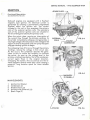
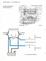
IGNITION
.SPARK PLUGS
Functional Description:
(See SCHEMATIC FIG. 3-8)
\ '
Rockwell engines are equipped with a flywheel
magneto type ignition . An electrical current is
generated by rotating a permanently magnetized
flywheel about the ignition coil. The current
initiated in this coil in turn energizes the primary
coi ls of the external ignition coils. The secondary
coils of the external ignition co i ls are situated in
the force field generated by the primary coils.
When the points close, causing an interruption of
the current flow through the pr i mary winding, its
force field immediately co ll apses and generates a
very high voltage in the second coil. This voltage in the
region of severa l thousand volts wil l jump the spark
plug gap causing ignition to begin.
"
-
- ENGINE
CONNECTOR
The collapsing lines of force cut through the primary
windings , raising the voltage in that circuit also.
As this occurs , the condenser absorbs the generated current to reduce the tendency to overload
the points . As soon as the voltage level in the
primary winding drops be low that of the condenser,
current again f lows in the original direction,
energizing the system. This occurrence and the reversal happens several times each cycle creating a
powerful, long duration spark for more reliable
ignition .
FIG. 3-5
MAIN ELEMENTS:
1.
2.
3.
4.
5.
lg n ition Co i I (Stator)
Condensers (2)
Breaker Points (2)
Ignition Coi ls (External) (2)
Spark Plugs (2)
FIG. 3-6
3-3
SERVICE MANUAl - 1975 SCORPiON W II?
~G
SEE ENGINE DISASSEMBLY
!T~ON
COIL (STATOR)
(SECTION l ) FOR FLYWH EEL
AND STATOR REMOVAL
FIG. 3-7
CONDENSER
HI·
,..._.:11..~
SPARK PLUG
EXTIEIRNAl iG ITION COILS
~SPARK
f iG. 3-8 IGNITiON SCHEMATIC
ENGiNE CONNECTOR
3-4
PLUG
SERVICE MANUAL - 1975 SCORPION WHIP
r----
STATOR IGNITION COIL TO
EXTERNAl COIL CONNECTORS
FIG. 3-9
(
EXTERNAL COIL
COIL TO SPARK PLUG LEAD
EXTERNAL COIL
GROUND
FIG. 3-10
•
3 -5
SERVICE MANUAL- 1975 SCORPION WHIP
VOLTAGE REGULATION
Functio nal Description:
The voltage regulator is connected across th e
lighting coils in parallel with th e electrical load
of the sled. (See SCHEMATIC - ELECTRICAL DISTRIBUTION AND CONTROL - FIG . 3-16). Under operating
conditions, th e voltage drop across the r egu lator is
such th at approximately 13.8 V RMS is supplied to
the snowmobile lighting circu it. Two types of
regulato rs are described in thi s section .
NORMAL LIGHTING COIL VOLTAGE
+
~
I
ALTERATION OF VOLT AGE
WAVE WHEN SCR
CONDUCTS
~0 ~~~~~~~~~~~---------
~,
Scorpion PIN 043299
(See FIGs. 3- 11, 3- 12 and 3-1 3)
MAIN ELEMENTS:
1.
2.
3.
4.
5.
TIME
FIGURE 3-11
Si Ii con Contro l Rectifier (SCR)
Resistors (R 1, R2, R3, R4, Trim)
Condenser (C 1)
Diodes (CR 1, CR2, CR3, CR4)
Tran sistors (Z1, Q1)
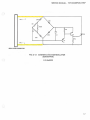
This so lid state regulator is al so a shunt type regula tor. When the magneto output drops below th e
specified pre-set r eg u Ia tor voltage level, the regu Iator drops ou t of the system, providing maximum
available voltage to the load at decreased speeds.
In th e first half of the operating cycle when line 1 i s
po sitive with r espect to line 2, C 1 will charg e
through CR 1, C 1, R2 and CR2 until the voltage drop
across C 1 reaches the level neces sary to cause Z 1
to conduct. At this point, Q1 will draw base current
and then pass current through CR 1, the emitter col lector of Q 1 and into th e gate of SCR. SCR is "turned
on" and shun ts the output of the magneto.
In the second half cycle the shunting mechanism of
the regulator is not operative.
If th e re is a sufficiently heavy load on th e magn e to
during the first half cycle, the load e ffectively holds
the voltage output to a value less than that required
to turn the SCR on and therefore full output goes to
the load.
3-6
VOLT AGE REGULATOR 043299
FIG. 3-12
SERVICE MANUAL - 1975 SCORPION WHIP
LINE 1-
j
Cl
LINE2 -
SCR
t.
L77777L77Z I Z7 1 7 / L // L I .~------------------------~----~
REGULATOR CONNECTOR
FIG: 3-13
MAGNETO VOLTAGE REGULATOR
(SOLID STATE)
PIN 043299
3-7
SERVICE MANUAL - 1975 SCORPION WHIP
ELECTRICAL CONTROL
AND DISTRIBUTION
Functional Description
Power is supp li ed continuous ly to the tachometer
m ec hanism and to the brake light switch, so that
any time power is being generate d, the tachometer
will indicate and the brake li ght will go on if the
brake is app lied .
Power to all the other items is supplied through the
ignition switch in the "LIGHTS" mode.
HEADLIGHT HARNESS CONNECTOR
IGNITION SWITCH
CONN
Grounding of the System is accomplished at three
locations:
1.
2.
3.
VOLTAGE REGULATOR
CONNECTOR-~
To the chassis at the rear end
To the chassis from wire harness
at eng. connector.
To the stator plate on the engine
MAIN ELEMENTS:
1.
2.
3.
4.
5.
6.
7.
Main Wiring Harness
Seat Wiring Harness
Taillight Wiring
Harness
Safety Stop Switch
Break Light Switch
Hi -lo Switch
Ignition Switch
(
HI-LO SWITCH
CONNECTOR
BRAKE LIGHT
SWITCH
CONNECTOR
'
SPEEDOMETER/TACHOMETER CONN. -~
SEAT HARNESS
CONNECTOR
f
ENGINE CONNECTOR
SAFETY STOP SWITCH CONNECTOR ' - ----.....,;.
FIG. 3-14
SAFETY STOP
SWITCH/HARNESS
~-------HI-LO
----~A'
BRAKE LIGHT
SWITCH/HARNESS
FIG. 3-15
3-8
SWITCH/HARNESS
I
I
/ f\ (i .· '·' (\' '
<.y_-.j~\.~V_{_;
~
I
SAFETY
STOP
SWITCH
•
·
n
· - · TACHOMETER
• • MOVEMENT
TACHOMETER &
SPEEDOMETER
LIGHTS
I
LLIGHTING
COIL
IG NITION
CO IL
/
/
--------,.r--y-.- ~
E
LIGHT
SWITCH
•
:::1:
m
)>
I
-
0
I"'"
C)
:t
-4
m
"'
;:10
•
<
n
.-
m
3:
)>
,_.::_-::::~~
TAILLIGHTS
BRAKE LIGHT
z
c
)>
,...
..0
......
U'l
"'
n
VOLTAGE
REGULATOR
~
~
D
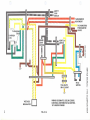
WIRING SCHEMATIC (COLOR CODED)
ELECTRICAL DISTRIBUTION & CONTROL
1975 SUPER STINGER
FIG. 3·16
0
;:10
-a
0
z
:E
:::1:
-a
SERVICE MANUAL - 1975 SCORPION WHIP
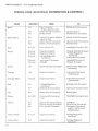
WIRING CODE (ELECTRICAL DISTRIBUTION & CONTROL)
COLOR
Black
FUNCTION
Hot
Hot
Hot
TO
FROM
Eng. Connector
(Engine Ignition Coil)
Safety Switch Connector
Brake Switch
Safety Switch Connector
Ignition Switch
Brake Switch Connector
Safety Switch Connector
Hot
Hot
Engine Connector (En g in e
Ignition Coil
Safety Switch Connector
Brake Switch Connector
Ignition Switch Connector
Brake Switch
Blue
Hot (Hi)
Hi-Lo Switch (Hi)
Headlight Connector (Hi)
Brown
Ground
Ground
Engine Connector
Engine Connector
Ground
Ground
Ground
Voltag e Regulator
Connector
Instrument Connector
Taillight
Chassis (Roll Bar Bracket)
Voltage Regulator
Connector
In strument Connector
Green
Hot
Ignition Switch Connector
Electric Start (Regulator
Connector)
Orange
Hot
Engine Connector
Instrument Connect or
(Tachometer)
Orange/Black
Ground
Engine Connector
Instrum ent Connector
(Tachome ter)
Red
Hot
Brake Switch Connector
Hot
Voltag e Reg ulato r
Connector
Brake Switch Connector
Ignition Switch Connect or
Tan
Hot
Brake Sw itch Connector
Brake Lights
White
Hot (LO)
Hi-Lo Switch Connector
(Lo)
Head I ight Connecto r (Lo)
Yellow
Hot
Hot
Hot
Ignition Switch Connector
Ignition Switch Connector
Hi-Lo Switch Con nector
Taillights
Hi-Lo Switch Connect o r
In strument Connector
(Lights- Tachometer,
Speedometer)
Yellow / Black
Ground
Engine Connector
Voltage Regulator
Connecto r
Yellow/Red
Hot
Engine Connect or
Voltage Regulator
Connector
Black/White
3-10
Hot
Head light Connector
Chassis (Tunnel)
SERVICE MANUAL - 1975 SCORPION WHIP
SPECIAL TESTING - ELECTRICAL
Regulator Tests
1.
Set point check (P /N 043299)
Use test circuit as shown below. Read voltage across regulator. Value should be
approximately 13.8 volts.
lOOW
5 ..n...
---·HI·-
----...N\1'-·
120V
OPEN
• TEST
24V
REGULATOR SET POINT TEST CIRCUIT
)
3-ll
SERVICE MANUAL - 197 5 SCORPION WHIP
TROUBLE SHOOTING (ELECTRICAL)
TROUBLE
No lights
Dim lights
Burned out
lights (all)
PROBABLE CAUSE
REMEDY
Open Ci r cu it :
Faulty Switch(s)
Separated Connector(s)
Cut Wiring
Repair or rep lace faulty
or damaged e lement.
Wiring shorted to ground:
Damaged In su lation
Repair or replace damaged
or faulty e lement.
Faulty Regulator (Shorted SCR)
Replace regulator.
Shorted or open lighting coi l.
Replace armature p late .
Faulty regulator- Inco rrect
r e gulator set point (too low).
Rep lace regulator.
Faulty regulator -Incorrect Set
Point (too high) .
Replace regulator and failed
bulbs.
(
Burned out
lights (individ ua l)
Fa iled bulb.
Replace bu lb.
Burned out lights
Intermittent short in wire harness.
Repair or r ep lace wire harness.
Engine won't run
l. Open or shorted winding s in
ignition co il s (stator).
2. Open or shorted windin gs.
in external ignition co il.
3. Shorted condenser- dirty o r
worn.
4 . Damaged (burned) points .
l. Rep lace armature p late.
Weak or no
spark
Engine won't runAdequate spark.
l. Burne d or f ouled plugs.
2. See Engine Trouble Shooting
Section
Unacce ptable
Engine Performance
3-12
See Engine Trouble Shooting
Section
2. Replace externa l coil.
3. Replace condenser.
4. Replace points.
l. Replace plugs. Determine that
correct plugs are b ei ng u sed.
CHECK ENGINE TROUBLE
SHOOTING.
. . _...
.
?•
1975
Scorpion
Whip
(
Service Manual
Clutch/Drive
Section
4-1
SERVICE MANUAL - 1975 SCORPION WHIP
DRIVE SYSTEM
Functional Description:
Th e main e lements included in thi s system are:
1. Drive Clutch
2. Drive Belt
3. Driven Clutch
4. Chain Case with sprockets, chain and chain tensioners.
5 . Drive shaft with track drive sprockets.
The power from th e eng ine is transmitte d through this system to the track in
sequence of elements li sted above to prope l the machine.
Th e drive clutch, belt and drive n clutch serve as a torque converter. The torque
conve rter on the snowmobile "down shifts" to a lower ratio as the track load increases as readily as it "up shifts" wh en the track load decreases.
To accomplish the automatic shifting, the movable sheave of the driven clutch
is fitted with a helical ramp which is gu i ded by a follower. This sheave is controlled by a spring pre-stressed in torsion and compression to hold the sheaves
together at the maximum p itch diameter.
)
Und er acceleration, th e torque from th e engine is greater than the demand
from the track . The drive c lutch then closes, forc ing the belt outward between
the sheaves. Belt tension and wedging action i s unbalanced at the driven clutch
and th e sheav e f aces are wedged open against the h e lical cam . This action
w inds up and compresses the spring.
Under steady running, all forc es are balanced and the belt chooses a ratio at
which this balance exists.
Under deceleration, the driven sheave i s stall ed slightly, whi ch unbalances the
forces so that th e sheave is forced to a new larger pitch diam e t e r. Be lt tension
is thus increased, the wedging action opens drive sheave and a new lower
pitch diameter is chosen to again bring all forces to balance.
j
4·2
SERVICE MANUAL - 1975 SCORPION WHIP
DRIVE CLUTCH DISASSEMBLY
1.
Raise hood and clutch guard. (See Figure 4 -1 )
FIG 4-1
2. Remove clutch attaching bolt and bell retaining bolt. Use impact wrench capable
of 75 or more ft. lbs. torqu e (In the field
alternate method may be used.) Making
sure ignition is off, run engine up on
compression using %" socket and
ratchet. Strike ratchet with plastic or
rubber mallet. (See Figure 4-2).
FIG 4-2
3. Remove bell housing (See Figure 4-3.)
FIG. 4-3
4 -3
SERVICE MANUAL- 1975 SCORPION WHIP
4
Movable sheave should slide off spline
easi ly. Next remove spring and retainer.
(See Figure 4-4.)
FIG 4-4
5. Remove snap ring retainer and idler bearing
if necessary. (See Figures 4-5 and 4-6.)
~/
FIG. 4-5
FIG. 4-6
4 -4
SERVICE MANUAL· 1975 SCORPION WHIP
(
6. If necessary to remove stationary sheave, insert plug (2 13/16" long x 3/4" diameter) in
stationary center hole and re-insert bell
retainer bolt. Tightening bell bolt will force
stationary off crankshaft. (See Figure 4-7.)
FIG. 4-7
7. Removing torque plug retainer will allow
torque plug to be removed and inspected.
(See Figure 4-8.)
FIG. 4-8
(
;
4-5
SERVICE MANUAL · 1975 SCORPION WHIP
)
8. Detaching springs and weight arm retainers
will allow weight arms to be removed. (See
Figures 4-9, 4-10, 4-11.)
DRIVE CLUTCH INSPECTION
FIG. 4-9
Inspect weight arm bushings and rollers for
cracks and flat spots. Also check snap rings on
weight arm shaft ends.
Inspect torque plug for fit and wear. (Should have
no more than .020" space between torque plug
and casting.)
Inspect idler bearing for freedom of rollers and
retention of lubricant.
FIG. 4-10
Inspect snap ring groove on stationary and spring
retainer for wear.
Inspect bell housing for cracks, particularly in
center area near spline.
)
FIG. 4·11
4-6
SERVICE MANUAL · 1975 SCORPION WHIP
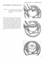
RE-ASSEMBLY OF DRIVE CLUTCH
'
CAUTION:
If stationary has been removed,
assure that there is no grease on
either the shaft or sheave before reassembly.
Re-install idler bearing, snap ring, retainer
and spring. Place weight arms on movable
sheave (after checking them for lubrication).
Attach retainers, checking to see that the
small locating hole in the bearing aligns with
the detent on inner face of retainer. Install
torque plug and torque plug retainer. Install
bell housing, checking alignment with stub
on torque plug provided for this purpose .
Place spring washer and bell retainer bolt on
next, assuring that the bolt has bottomed out
securely in proper a.lignment. Install clutch
attaching bolt. Torque on both bolts to 50 ft.
lbs.
r
)
4-7
SERVICE MANUAL - 1975 SCORPION WHIP
DRIVEN CLUTCH DISASSEMBLY
1.
Remove brake cable at chain case end.
DRIVEN SHAFT LOCKING BOLTS
2. Remove chain tensioners, unbolt and remove
top sprocket and chain .
CHAIN---------------~~~~~
CHAIN TENSIONER--------------t
FIG. 4-12
FIG. 4-12A
4-8
SERVICE MANUAL • 1975 SCORPION WHIP
3. Remove driven unit from chaincase (tapping
shaft lightly with plastic mallet). Remove
snap ring and washer from cam top and slide
off shaft. {See Figures 4 -13, 4-14, 4-15.}
CAM TOP
(
)
FIG.4-13
FIG. 4-14
FIG.4-15
4-9
SERVICE MANUAL· 1975 SCORPION WHIP
4. Remove key and main spring. (See Figure 4-
16.)
KEY
FIG. 4-16
5. This should allow cam bottom and movable
sheave to be removed as a unit (See Figure
4-17.), and disassembled if necessary. (See
Figure 4-18.)
(
-,
FIG. 4-17
FIG.4-18
4-10
)
SERVICE MANUAL- 1975 SCORPION WHIP
6. Stationary sheave may then be unbolted
from clutch shaft (See Figures 4 -19 and
4 -19A) and bearings can be pressed off
if necessary.
STATIONARY SHEAVE
CLUTCH SHAFT
FIG. 4-19
FIG. 4-19 A
(
4- 11
SERVICE MANUAL - 1975 SCORPION WHIP
DRIVEN CLUTCH INSPECTION
In spect snap ring groove for wear.
In spect He lical ramps for wear and breakage.
(See Fig. 4-13)
Inspect bronze bushing in cam bottom for any
sig ns of looseness or slippage_ (should be staked
in solidly).
Ro tate and check bearings visually.
Inspect she aves for cracks particularly around
bolt ho les .
Check splines and threads on sprocket side of
m a in shaft for w e ar, crossthreading, etc.
RE-ASSEMBLY OF DRIVEN CLUTCH
Attach stationary sheave to clutch shaft. Assemble cam bottom and movable, then place on shaft
f o ll ow ed by the woodruff key and main spring .
Place cam top on shaft, preloading spring lj3 turn
and install washer and snap ring.
Upo n replacing the driven clutch in chaincase,
check to a ssure that the 0-ring in chaincase bore
is intact and in good condition. Also check 0-ring
in chaincase cover before installation. Connect
brake cable. (See Fig. 4 -12).
4- 12
SERVICE MANUAL • 197 5 SCORPION WHIP
DRIVE BELT SPECIFICATIONS
(
Drive belt width
1 1 /8 - 1 3/16 inches
Drive belt outside diameter
inches.
43 1/8 - 43 1/4
Clutch offset (Drive to Driven)- 3/8 inch
Center to center distance- 10 1/2 inches
(Drive clutch to Driven clutch)
I
(.
0
ALIGNMENT BAR
(FOR MEASURING 3/8" OF
DRIVEN CLUTCH--
FIG. 4-20
(
4- 13
SERVICE MANUAL - 1975 SCORPION WHIP
CHAIN CASE DISASSEMBLY
Remove brake cable at chain case end. Remove
cover, tensioners, upper and lower bolts. Remove
sprockets with chain. Remove bearing flange bolts
and brake cable. Taking care to check number of
shims between the chaincase and the tunnel and
their specific locations, remove the chaincase from
the tunnel. When the chaincase is reassembled to
tunnel, assure that the spacers go back where they
were. Before tightening case to tunnel be sure to
adjust case to achieve correct center distance of 10 1/2" between center of driven and drive clutches.
Reverse procedure to install.
REMOVAL OF FRONT DRIVE SHAFT
Remove brake cable at chain case end. Remove
chaincase cover, tensioners, lower sprocket and
chain. Loosen locking collars on front drive
bearings (see Fig. 4-21 ). Remove speedometer,
drive adaptor and flanges. Slide drive shaft
through chaincase mounting hole until right side
clears main frame and remove. (It is necessary to
detach forward end of pararail to gain clearance
for entire removal of front drive shaft - See Suspension Section.)
REMOVAL OF FRONT DRIVE SPROCKET
Punch out spirol pins (see Fig. 4-21, 4-22). Then
taking care to see that the shaft is clean, slide
sprockets off. To reassemble, reverse procedure.
LOCKING COLLARS
FIG. 4-21
4-14
SERVICE MANUAL · 1975 SCORPION WHIP
)
BEARING
COLLAR
0-RING
BEARING FLANGES-L-------'
Inspection of Drive Shaft
Observe shaft for signs of stress, cracks and bending, check bearings and collars for breakage.
Check sprockets for loosening of pin holes.
NOTE : Small cracks in the white material of the
drive sprocket are not signs of failure, but a result
of shrinkage during manufacture.
4-15
SERVICE MANUAL- 1975 SCORPION WHIP
TROUBLE SHOOTING
(
The operating diameter of the drive and driven
clutch governs the ratio of reduction or advantage in the snowmobile drive train. Therefore,
to gain maximum performance and economy,
these areas cannot be overlooked.
The following are some symptoms, causes and
cures to aid in trouble shooting the clutch/
drive system.
Engine Overspeed:
Excessive
vibration of
drive train:
Excessive noise
from front drive
system:
4-16
REMEDY
CAUSE
TROUBLE
Drive clutch may not be closing fully. This can
be checked by drawing a line on the face of
the sheave (drive or driven) with a crayon
from the center outward. Then running the
machine at top speed will tell you how far
the clutch closed by erasure of the line by the
belt.
Disassemble clutches
examine and replace
malfunctioning parts.
If the clutch is closing fully, the belt may be
wrong length or the center to center distance
of the clutches may be off. Finally, check the
number of teeth on upper and lower
sprockets.
Replace belt. Correct
center to center distance (see belt specs .)
Replace
incorrect
sprocket.
Tachometer
(high)
incorrectly
Replace tach.
Belt may be worn and too narrow to achieve
correct ratio (see belt specs).
Replace belt.
may
be
reading
Track may be too loose allowing sprockets to
slip over drive lugs or "ratchet".
Correct track tension.
Chain may
sprockets.
Check and
replace
broken
or
weak
chain tensioners.
be
slipping
over
teeth
on
Malfunction of front drive bearings.
Replace bearings.
Cha1n case may be dry of oil.
Disassemble
and
check - chain, sprockets and chain case
cover seal (0 ring) re place worn parts and
reassembl e _
Refill
with oil check level
and check for leaks.
( )
1975
Scorpion
Whip
Service Manual
Suspension
Section
5-l
SERVICE MANUAL - 1975 SCORPION WHIP
FUNCTIONAL DESCRIPTION:
The four main elements of a snowmobi le suspension are:
1.
2.
3.
4.
Skis
Track Suspension
Seat
Operator
All elements work together to perform the suspension functions to th e optimum degree.
The suspensions are basically designed to:
1.
2.
3.
4.
Protect the operator from physical abuse or
injury.
Keep the operator from being ejected from
his operating position and controls.
Prevent damage to the machine.
Increase ground contact and improve trac tion.
(
On the 1975 Whip, the track suspension ("ParaRail® - Snowmobile Suspension") is a unit type
suspension which simply means that it is a single
unit working as a whole as opposed to the
multiple unit, bogey type suspension. It also
possesses the advantage of being ab l e to tra verse marginal snow conditions without damaging effect s to the suspension system.
NOTE: The suspension on the 1975 Whip may
have ei ther two or three rear idler wheels, depending on time of manufacture. All pictures and
diagrams show the three rear idler ! system.
Assembly and disassembly procedure for. the two
idler sys t em i s the same as shown for the three
idler system with minor changes.
l
[
5 -2
SERVICE MAN UAL - 1975 SCORPIO N WHIP
(
(
FIG. 5-1 "PAR A-RAIL ®" G ROUP
c
5-3
SERVICE MANUAL- 1975 SCORPION WHIP
SUSPENSION SYSTEM- REMOVAL, DISASSEMBLY, ASSEMBLY
)
For the removal, maintenance and installation of
the "Para-Rail ® - Snowmobile Suspension", we
will refer to the "Para-Rail" group for identification of component parts by the numbers 1
through 57 .
(A) REMOVAL
1.
Remove the two hex cap screws, #56 and
wash ers , #57.
2.
Rai se and block rear of vehicle off the
ground.
NOTE:
FIG. 5-2
In Figs. 5-3 through 5-6 the track ha s been
re moved for clarity of illustration.
3.
Remove the two nuts, #51, from the two eye
bolts, #11.
FIG. 5-3
I
5·4
I
SERVICE MANUAL - 1975 SCORPION WHIP
4.
Remove the two whiz lock screws, #20
securing the rear suspension plates to the
rear axle.
)
5.
Rel e ase the track tension
two scr ews, #46.
by loosening the
FIG. 5-4
(
6.
Remove hex screws, #53 and nut, #54, on the
two suspension plates. Remove plates.
FIG. 5-5
(
FIG. 5-6
5·5
SERVICE MANUAL - 1975 SCORPION WHIP
7.
Remove the two whiz lock screws , #20,
located on the side of the tunnel in front of
the footrests.
The para-rail can now be r e moved from the
track and tunnel.
(B) DISASSEMBLY- "PARA-RAIL ® -SNOWMOBILE
SUSPENSION"
1.
FIG. 5-7
Bracket - axle adjustme nt #42
)
Remove the four (4) hex scre ws, #21 and
lock nuts, #22.
FIG. 5-8
5 -6
SERVICE MANUAL - 1975 SCORPION WHIP
2.
Springs #2 - #4
Place suspension on the floor and install
spring release tool.
To release the springs from th e spools, #18,
th e r ear of "Para-Roil ® - Snowmobile
Suspension" must b e held down whil e downword pressu re i s applied with the right arm
and upward pressure with the left arm .
3.
FIG. 5-9
Linkage Arm #30
Remove the two screws , #25, washers
#26 and #48.
FIG. 5-10
Remove the two button head screws,
#33 and spring retainers, #32.
0
~
FIG. 5-11
5-7
SERVICE MANUAL - 1975 SCORPION WHIP
4.
Bogey Whee l #29.
Remove shaft, #28, and this will allow the
bogey wheel #29 , tube spacers , #8, tube
spacers, #49, bearing, #5, and remaining
washers, #48, to be free from suspension.
(Fig . 5-12.)
~
..it.
;:g~·---Lf·
FIG. 5-12
I
5.
Spools #18
Remove the two screws , #25, and washers,
#26, from the wheel shaft, #23. Push shaft
through rails, #6 and spools are removed.
(Fig . 5- 13.)
6.
(
Rails #6
Remove the remaining eight (8) screws, #25,
and washers, #26. This will allow the rails to
be rem oved from the remaining shafts,
bogey whee l s, and tube spacers. The "ParaRail ® - Snowmobile Suspension" is completely disassembled at this time.
FIG. 5-13
FIG. 5-14
5-8
SERVICE MANUAL · 1975 SCORPION WHIP
(C) ASSEMBLY
1.
Prior to assembly procedure, ensu re that all
components are clean and a ll defective parts
have been replaced.
2.
Apply a coat of low temperature grease to all
shafts prior to assembly. (Scorpion clutch
lube 906800 may be used.)
3.
Reverse procedure as outlined for disassembly.
NOTE: Ensure that all tube spacers and bogey
wheels are assembled in th ei r respective areas
on the shafts.
Torque requirements for assembly are:
( )
ITEMS
TORQUE
20
50-60 Ft-Lbs.
21
1 5-19 Ft-Lbs
22
15- 19 Ft-Lbs
25
1 5- 19 Ft-Lbs
53
1 5-1 9 Ft-Lbs
54
15-19 Ft-Lbs
(
'
5-9
SERVICE MANUAL - 1975 SCORPION WHIP
SPECIAL ADJUSTMENTS
"PARA-RAIL ® -SNOWMOBILE SUSPENSION"
ADJUSTMENT
The rear spring adjustment governs preload and
should be correlated with the weight of the rider
or riders normally using the machine .
Too much spring tension will result in a harsh ride
and increases the weight carried on the skis, thus
increasing steering effort.
Too little spring tension will result in the bottoming out of the suspension, a harsh ride and
shortened life to the suspension components will
occur.
1.
The proper spring tension may be obtained
by having the rider(s) sit on the machine, in
the normal sitting position and measure the
distance between the floor and the bottom of
the running board at the rear of the machine
(either side). This measurement must be
4 1/2" to 6".
2.
To adjust, loosen the nuts on the eye bolts
and adjust accordingly, making certain that
each spring is tightened or loosened the
same amount.
3.
Repeat Step 1, and tighten th e nuts on the
eye bolts securely when the 4 1/2" to 6"
measurement is attained .
(
)
NOTE: When 300 lbs. (combined passenger
weight) is normally carried on machine, a "heavy
duty" spring kit should be installed on machine .
This kit is available at your Scorpion Distributor
as an accessory item.
)
5-l 0
SERVICE MANUAL - 1975 SCORPION WHIP
"PARA-RAIL ® -S NOWMOBILE SUSPENSION": TRACK TENSION
(
Proper track tension is extreme ly importa nt
to assure long life of all associated components and efficiency of the t rack drive
system .
4.
Insert both "Track Jacks" be tween th e
track and both bogey wh ee ls, located on
the third bogey axle, ahead of the rear
idler wheels.
5.
If the track is properly tensioned, the
green ring should be just vi sible or
aligned with the lip of the cylinder. Ad ju stment i s required if the green ring i s
not visible, or is above the lip of the
cylinder.
6.
To make adjustment, loosen the lock
nuts on the track adjustment bolts, as
well as the rear suspension mounting
screws (rear of tunnel just below seat),
and e i ther tighten or loosen the adjustment bolts until proper adjustment is
measured on both "Track Jacks " (green
ring aligned with lip on cylinder).
7.
Retighten the lock nuts on th e track adjustment bolts , as well as the rear
suspension mounting screws.
The track tension should be checked at the
fo ll owing interva ls:
1.
2.
3.
When the machin e is new (dealer
preparation).
After the first 10 hours.
Every 30 days, or 200 miles of operati o n.
4.
At the start of each snow season .
The following procedu r e app lies t o all "ParaRai l ® - Snowmobi le Suspension " equipped
Scorpion snowmobi les:
c
1.
The t rack should be at roo m tem perature or should have been recently
run to remove any stiffness, caused by
co ld weather.
2.
Elevate the rear of the machine.
3.
Adjust each "Track Jack " to one and one
quarter inch ( 1 V4).
NOTE: Tra ck Jacks " are available at Scorpion, Inc. It is an accessory item, Part
#90 173&.
REAR SUSPENSION
MOUNTING SCREWS
------i"-_,~.J'
TRACK ADJUSTMENT
BOLTS ----------------~
(
FIG. 5-16
5 - ll
SERVICE MANUAL - 1975 SCORPION WHIP
IN THE EVENT "Track Jacks" are not avai lable, the
following procedure may be employed to achieve
track tension:
l.
The track should be at room temperature or
should have been recently run to remove any
stiffness, caused by cold weather.
2.
Elevate the rear of the machine.
3.
Apply ten ( l O) lbs. of force or weight evenly
distributed across the track under both
bogey wheels, located on the third bogey
axle, ahead of the rear idler wheels.
4.
To make adjustment, loosen the lock nuts on
the track adjustment bolts, as we l l as the
rear suspension mounting screws (rear of
tunne l just below seat), and either tighten or
loosen the adjustment bolts to achieve the
1 1/4 inch clearance between track and bogey
wheels.
5.
Remove ten (l 0) lbs. force or weight and
retighten the lock nuts on the track adjustment bolts, as well as the rear suspen sion mounting screws .
)
)
5- 12