1
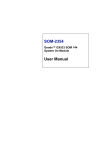
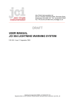
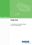
UNO-2053E
GX2-400 Universal Network
Controller with PC Card,
2xLAN, 2xUSB, 2xRS-232, Audio
User Manual
Copyright Notice
The documentation and the software included with this product are copyrighted 2006 by Advantech Co., Ltd. All rights are reserved. Advantech
Co., Ltd. reserves the right to make improvements in the products
described in this manual at any time without notice. No part of this manual may be reproduced, copied, translated or transmitted in any form or
by any means without the prior written permission of Advantech Co., Ltd.
Information provided in this manual is intended to be accurate and reliable. However, Advantech Co., Ltd. assumes no responsibility for its use,
nor for any infringements of the rights of third parties, which may result
from its use.
Acknowledgements
IBM, PC/AT, PS/2 and VGA are trademarks of International Business
Machines Corporation.
Intel® and Pentium® are trademarks of Intel Corporation.
Microsoft Windows and MS-DOS are registered trademarks of
Microsoft Corp.
C&T is a trademark of Chips and Technologies, Inc.
All other product names or trademarks are properties of their respective
owners.
Part No. 2003205320
1st Edition
Printed in Taiwan
August 2006
UNO-2053E User Manual
ii
Product Warranty (2 years)
Advantech warrants to you, the original purchaser, that each of its products will be free from defects in materials and workmanship for two years
from the date of purchase.
This warranty does not apply to any products which have been repaired or
altered by persons other than repair personnel authorized by Advantech,
or which have been subject to misuse, abuse, accident or improper installation. Advantech assumes no liability under the terms of this warranty as
a consequence of such events.
Because of Advantech’s high quality-control standards and rigorous testing, most of our customers never need to use our repair service. If an
Advantech product is defective, it will be repaired or replaced at no
charge during the warranty period. For out-of-warranty repairs, you will
be billed according to the cost of replacement materials, service time and
freight. Please consult your dealer for more details.
If you think you have a defective product, follow these steps:
1.
Collect all the information about the problem encountered. (For
example, CPU speed, Advantech products used, other hardware
and software used, etc.) Note anything abnormal and list any
onscreen messages you get when the problem occurs.
2.
Call your dealer and describe the problem. Please have your manual, product, and any helpful information readily available.
3.
If your product is diagnosed as defective, obtain an RMA (return
merchandize authorization) number from your dealer. This allows
us to process your return more quickly.
4.
Carefully pack the defective product, a fully-completed Repair and
Replacement Order Card and a photocopy proof of purchase date
(such as your sales receipt) in a shippable container. A product
returned without proof of the purchase date is not eligible for warranty service.
5.
Write the RMA number visibly on the outside of the package and
ship it prepaid to your dealer.
iii
CE
This product has passed the CE test for environmental specifications
when shielded cables are used for external wiring. We recommend the use
of shielded cables. This kind of cable is available from Advantech.
FCC Class A
This equipment has been tested and found to comply with the limits for a
Class A digital device, pursuant to part 15 of the FCC Rules. These limits
are designed to provide reasonable protection against harmful interference when the equipment is operated in a commercial environment. This
equipment generates, uses, and can radiate radio frequency energy and, if
not installed and used in accordance with the manual, may cause harmful
interference to radio communications. Operation of this equipment in a
residential area is likely to cause harmful interference in which case the
user will be required to correct the interference at his own expense.
Technical Support and Assistance
Step 1. Visit the Advantech web site at www.advantech.com/support
where you can find the latest information about the product.
Step 2. Contact your distributor or Advantech's customer service center
if you need additional assistance. Have the following info ready:
- Product name and serial number
- Description of your peripheral attachments
- Description of your software (OS, version, software, etc.)
- A complete description of the problem
- The exact wording of any error messages
Packing List
Before setting up the system, check that the items listed below are
included. If any item is not, please contact your dealer immediately.
The UNO-2053E comes with the following items:
• Warranty certificate
• Software Supporting CD-ROM
• 6P-6P-6P 20cm KB and PS/2 Mouse Y cable (P/N: 1652002202)
• Phoenix power connector (P/N 1652002202)
• DIN-rail mounting accessory
UNO-2053E User Manual
iv
Contents
Chapter
Chapter
Chapter
1 UNO-2053E Overview .................................... 2
1.1
1.2
1.3
1.4
Introduction ....................................................................... 2
Hardware Specifications ................................................... 2
Safety Precautions ............................................................. 4
UNO-2053E Series............................................................ 5
1.5
Chassis Dimensions........................................................... 6
1.4.1
Packing List ................................................................... 5
Figure 1.1:Chassis Dimensions ...................................... 6
2 Hardware Functionality ................................. 8
2.1
UNO-2053E Peripherals ................................................... 8
2.2
2.3
2.4
2.5
2.6
2.7
2.8
2.9
2.10
2.11
COM1~COM2: RS-232 Interfaces ................................... 8
LAN: Ethernet Connector ................................................. 8
Power Connector ............................................................... 9
LED Indicators .................................................................. 9
PS/2 Keyboard and Mouse Connector .............................. 9
Universal Serial Bus Connectors....................................... 9
PCMCIA: PC Card Slot .................................................... 9
VGA: VGA Display Connector ...................................... 10
RESET: Reset Button...................................................... 10
Audio............................................................................... 10
Figure 2.1:UNO-2053E Front Panel .............................. 8
Figure 2.2:UNO-2053E Rear Panel ............................... 8
3 Initial Setup.................................................... 12
3.1
3.2
CompactFlash Card Installation ...................................... 12
Chassis Grounding .......................................................... 12
3.3
3.4
Power Connection ........................................................... 12
BIOS Setup and System Assignments ............................ 12
Figure 3.1:Chassis Grounding Connection .................. 12
Appendix A Pin Assignments ............................................ 14
A.1
Board Connectors and Jumpers....................................... 14
A.2
RS-232 Serial Port 9C (COM1~C0M2)(Male DB9) ...... 16
A.3
Ethernet RJ-45 Connector (LAN1~LAN2)..................... 16
A.4
Phoenix Power Connector (C)......................................... 17
A.5
PS/2 Keyboard and Mouse Connector (KM1) ................ 17
A.6
USB Connector (CON1, CON2)..................................... 18
Figure A.1:Connector & Jumper Locations (Top) ....... 14
Figure A.2:Connector & Jumper Locations (Bottom) . 14
Table A.1:UNO-2053E Connectors & Jumpers .......... 15
Table A.2:RS-232 Serial Port Pin Assignments .......... 16
Table A.3:Ethernet RJ-45 Connector Pin Assigns ....... 16
Table A.4:Phoenix Power Connector Pin Assigns ...... 17
Table A.5: ................................................................... 17
Table A.6:Keyboard & Mouse Connector Pin Assigns 17
Table A.7:USB Connector Pin Assignments ............... 18
v
Table of Contents
A.7
VGA Display Connector (VGA1)................................... 18
A.8
A.9
CompactFlash Master/Slave Jumper Setting (JP2) ......... 19
Enhanced IDE Connector (CN2) .................................... 20
UNO-2053E User Manual
Table A.8:VGA Adaptor Cable Pin Assignments ....... 18
Table A.9:IDE Hard Drive Connector Pin Assigns ..... 20
vi
CHAPTER
1
UNO-2053E Overview
This chapter gives background information on the UNO-2053E. It shows you the
UNO-2053E overview and specifications.
Sections include:
• Introduction
• Hardware Specifications
• Safety Precautions
• UNO-2053E Series
• Chassis Dimensions
Chapter 1 UNO-2053E Overview
1.1 Introduction
Are you looking forward to a suitable embedded Application Ready Platform (ARP) that could shorten your development time and offer rich networking interfaces to fulfill your extensive needs in different kind of
projects? Advantech Universal Network Controller (UNO-2000 series) is
your ANSWER concentrating the services on Network-enabled Application Ready Platform total solution.
Leveraging field-approved and worldwide-awareness real-time OS technology, Advantech UNO-2000 series provides Windows CE .NET ready
solution and support several standard networking interfaces, such as Ethernet, Wireless LAN, RS-232/422/485 and so on. Because of its openness, great expansion capability and reliable design – fanless and
diskless, Advantech UNO-2000 series becomes an ideal embedded platform to implement custom applications in diversified applications.
1.2 Hardware Specifications
• CPU:
AMD Geode GX533-400
• Chipset: AMD CS5535
• BIOS:
AWARD 4Mbit FLASH BIOS
• RAM:
256MB DDRRAM on board
• VGA:
Supports VGA and VESA
- Display memory: 1 ~ 16 MB share memory, set in BIOS
- CRT display: Non-interlaced CRT monitors resolutions up
to 1280 x 1024 @ 256 colors or 1024 x 768 @ 24 bpp
- DB-15 VGA connector
• Audio:
- Microphone
- Line In
- Line Out
UNO-2053E User Manual
2
• Serial Port: Two standard RS-232 ports
- IRQ: All ports use the same IRQ assigned by BIOS
- Data bits: 5, 6, 7, 8
- Stop bits: 1, 1.5, 2
- Parity: none, even, odd
- Speed: 50~115.2 kbps
- Data signals: TxD, RxD, RTS, CTS, DTR, DSR, DCD, RI, GND
- Max data distance: 50 feet (15.2 meters)
• USB interface: USB OpenHCI, Rev. 1.0 compliant
USB specification version 1.1 compliant
• Ethernet Port:
Dual 10/100Base-T Ethernet
- LAN chip: Realtek 8139CL chipset supports
- LED on the front side
• PC Card: One PC Card slot
- Support CardBus (Card-32) Card and 16-bit (PCMCIA 2.1
JEIDA4.2) Card
- Support +5 V, +3.3 V and +12 V @ 120mA working power
• SSD: One Type I / Type II CompactFlash card slot inside the chassis
• LED: One power LED, one IDE LED
• Keyboard/Mouse connector: Mini-DIN connector supports PS/2 keyboard and a PS/2 mouse
• Power Supply Voltage: 10-30 VDC, reversed wiring protection
• Power Consumption: 15W (typical)
• Power Requirement: 24W
• Operating Temperature: 0 ~ 55° C (0 ~ 131° F)
• Chassis Size (W x L x H):164.8 x 106.5 x 35.5 mm (6.5" x 4.2" x 1.4")
• Weight: 0.8 kg
3
1.3 Safety Precautions
The following sections tell how to make each connection. In most cases,
you will simply need to connect a standard cable. All of the connector pin
assignments are shown in Appendix A.
Warning!!
Always disconnect the power cord from your chassis
when you are working on it. Do not connect while the
power is on. A sudden rush of power can damage sensitive electronic components. Only experienced electronics personnel should open the chassis.
Caution!!
Always ground yourself to remove any static electric
charge before touching UNO-2053E. Modern electronic devices are very sensitive to static electric
charges. Use a grounding wrist strap at all times.
Place all electronic components on a static-dissipative
surface or in a static-shielded bag..
UNO-2053E User Manual
4
1.4 UNO-2053E Series
There are two products in UNO-2053E series listed as below:
• UNO-2053E:
UNO-2053E hardware platform
• UNO-2053ECE: UNO-2053E hardware platform with WinCE OS
(built in 128MB CompactFlash card)
• UNO-2053EXP: UNO-2053E hardware platform with WinXPe OS
(built in 1GB CompactFlash card)
1.4.1 Packing List
Before installing your board, make sure that the following materials have
been received:
Common Parts:
• Warranty certificate
• Software Supporting CD-ROM
• 6P-6P-6P 20cm KB and PS/2 Mouse Y cable (P/N: 1652002202)
• Phoenix power connector (P/N 1652002202)
• DIN-rail mounting accessory (1997001110, 1997001120, 1997001130,
1997001140)
For UNO-2053ECE:
• Built in 128 MB CompactFlash card with Microsoft Windows CE OS
• End User License Agreement for Windows CE
For UNO-2053EXP:
• Built in 1GB CompactFlash card with Microsoft WinXPe OS
• End User License Agreement for WinXPe
If any of these items are missing or damaged, contact your distributor or
sales representative immediately.
5
1.5 Chassis Dimensions
Figure 1.1: Chassis Dimensions
UNO-2053E User Manual
6
CHAPTER
2
Hardware
Functionality
This chapter shows how to set up the
UNO-2053E’s hardware functions, including connecting peripherals, switches and
indicators.
Sections include:
•UNO-2053E Peripherals
•COM1~COM2: RS-232 Interfaces
•LAN: Ethernet Connector
•Power Connector
•LED Indicators
•PS/2 Keyboard and Mouse Connector
•Universal Serial Bus Connectors
•PCMCIA: PC Card Slot
•VGA: VGA Display Connector
•RESET: Reset Button
•Audio
Chapter 2 Hardware Functionality
2.1 UNO-2053E Peripherals
The following two figures show the connectors on UNO-2053E. The following sections give you detail information about function of each
peripheral.
Figure 2.1: UNO-2053E Front Panel
Figure 2.2: UNO-2053E Rear Panel
2.2 COM1~COM2: RS-232 Interfaces
The UNO-2053E offers two standard RS-232 serial communication interface ports on COM1 and COM2. Please refer to A.2 for pin assignments.
2.3 LAN: Ethernet Connector
The UNO-2053E is equipped with two Realtek RTL8139CL Ethernet
LAN controllers that are fully compliant with IEEE 802.3u 10/100Base-T
CSMA/CD standards. The Ethernet port provides a standard RJ-45 jack
onboard, and LED indicators on the front side to show its Link (Yellow
LED) and Active (Green LED) status. Please refer to A.3 for its pin
assignments.
UNO-2053E User Manual
8
2.4 Power Connector
The UNO-2053E comes with a Phoenix connector that carries 10~30
VDC external power input, and has reversed wiring protection. Therefore, it will not cause any damage to the system by reversed wiring of
ground line and power line. Please refer to A.4 for its pin assignments.
2.5 LED Indicators
There are two LEDs on the UNO-2053E front panel for indicating system
status: PWR LED is for power status and IDE LED is for IDE bus status.
2.6 PS/2 Keyboard and Mouse Connector
The UNO-2053E provides a PS/2 keyboard and PS/2 mouse connector. A
6-pin mini-DIN connector is located on the rear panel of the UNO-2053E.
The UNO-2053E comes with an adapter to convert from the 6-pin miniDIN connector to two 6-pin mini-DIN connectors for PS/2 keyboard and
mouse connections. Please refer to Appendix A.5 for pin assignments.
2.7 Universal Serial Bus Connectors
The USB connector is used for connecting any device that conforms to
the USB interface. Many recent digital devices conform to this standard.
The USB interface supports Plug & Play, which enables you to connect or
disconnect a device whenever you want without turning off the computer.
The UNO-2053E provides two connectors with USB interfaces, which
gives complete Plug & Play and hot swapping for up to 127 external
devices. The USB interface complies with USB specification version 1.1
compliant. OpenHCI, Rev. 1.0. The USB interface can be disabled in the
system BIOS setup. Please refer to Appendix A.6 for its pin assignments.
2.8 PCMCIA: PC Card Slot
The UNO-2053E provides one PC Card slot that supports CardBus
(Card-32) Cards and 16-bit (PCMCIA 2.1/JEIDA 4.2) Card standard. It
supports +3.3 V, +5 V and +12 V@120 mA working voltage.
PC Card is 85.6 mm long by 54 mm wide (3.37" x 2.126"), use a 68-pin
connector and is a removable module standardized by PCMCIA. PC Card
is also known as PCMCIA card. PCMCIA interrupt assignment is IRQ 9.
9
2.9 VGA: VGA Display Connector
The UNO-2053E provides a VGA controller for a high resolution VGA
interface. It supports VGA and VESA, up to 1280 x 1024 @ 256 color
and 1024 x 768 @ 24bpp resolution and up to 16 MB share memory. The
VGA interface is reserved for system testing and debugging.
2.10 RESET: Reset Button
Pressing the “RESET” button will reset UNO-2053E.
2.11 Audio
UNO-2053E supports audio function with
- Microphone
- Line In
- Line Out.
UNO-2053E User Manual
10
CHAPTER
3
Initial Setup
This chapter shows how to initial the
UNO-2053E, sections include:
Sections include:
• Insert CompactFlash Card
• Chassis grounding
• Connect the Power
• BIOS Setup and System Assignments
Chapter 3 Initial Setup
3.1 CompactFlash Card Installation
The procedure for installing a CompactFlash card into the UNO-2053E is
as follows, please follows these steps carefully.
Step 1: Remove power cord.
Step 2: Unscrew four screws from the rear panel of the UNO-2053E.
Step 3: Remove the rear panel.
Step 4: Plug a CompactFlash card with user’s OS and application
program into a CompactFlash card slot on board.
Step 5: Screw back the rear panel with four screws.
3.2 Chassis Grounding
Please connect the chassis ground of UNO-2053E with "EARTH".
Figure 3.1: Chassis Grounding Connection
3.3 Power Connection
Connect the UNO-2053E to a 10 ~ 30 VDC power source. The power
source can either be from a power adapter or an in-house power source.
3.4 BIOS Setup and System Assignments
UNO-2053E uses the Advantech SOM-2354 CPU module. For UNO2053E BIOS setup and system assignments, you can refer to SOM-2354’s
Chapter 4 “Award BIOS Setup” and Appendix A “System Assignments”.
The SOM-2354 user’s manual is in the “Manual” folder on the CD-ROM.
Please note that you can try to “LOAD BIOS DEFAULTS” from the
BIOS Setup manual if UNO-2053E does not work properly.
UNO-2053E User Manual
12
APPENDIX
A
Pin Assignments
This appendix shows the UNO-2053E pin
assignments
•Board Connectors and Jumpers
•RS-232 Serial Port
•Ethernet RJ-45 Connector
•Phoenix Power Connector
•PS/2 Keyboard and Mouse Connector
•USB Connector
•VGA Display Connector
•CompactFlash Master/Slave Jumper Setting
•Enhanced IDE connector
Appendix A Pin Assignments
A.1 Board Connectors and Jumpers
There are connectors and jumpers on the UNO-2053E board. The following sections tell you how to configure the UNO-2053E hardware setting.
Figure A-1 and figure A-2 show the locations of UNO-2053E connectors
and jumpers.
Figure A.1: Connector & Jumper Locations (Top)
Figure A.2: Connector & Jumper Locations (Bottom)
UNO-2053E User Manual
14
Table A.1: UNO-2053E Connectors & Jumpers
CN2
Internal IDE connector
CN3
Phoenix power connector
CN4
Internal CompactFlash card slot
CN6
PC Card slot
COM1
COM1 standard RS-232 serial port
COM2
COM2 standard RS-232 serial port
CON1
USB1 Connector
CON2
USB2 Connector
D6
IDE LED
D7
Power LED
J1
Reset button
JP2
CompactFlash IDE Primary Master/Slave Jumper
KM1
PS/2 Keyboard and Mouse connector
LAN1
Ethernet 1 RJ-45 connector
LAN2
Ethernet 2 RJ-45 connector
VGA1
VGA DB-15 connector
CN21
Line out
CN22
Line in
CN23
Mic in
15
A.2 RS-232 Serial Port 9C (COM1~C0M2)(Male DB9)
Table A.2: RS-232 Serial Port Pin Assignments
1
DCD
2
RxD
3
TxD
4
DTR
5
GND
6
DSR
7
RTS
8
CTS
9
RI
A.3 Ethernet RJ-45 Connector (LAN1~LAN2)
Table A.3: Ethernet RJ-45 Connector Pin Assigns
Pin
10/100Base-T Signal Name
1
XMT+
2
XMT-
3
RCV+
4
NC
5
NC
6
RCV-
7
NC
8
NC
UNO-2053E User Manual
16
A.4 Phoenix Power Connector (C)
Table A.4: Phoenix Power Connector Pin Assigns
Pin
Signal Name
1
+10~30 VDC
2
GND
A.5 PS/2 Keyboard and Mouse Connector (KM1)
PS/2 KB/MS Connector Pin Assignments
6
5
3
4
2
1
Table A.5:
Table A.6: Keyboard & Mouse Connector Pin Assigns
Pin
Signal Name
1
KB DATA
2
MS DATA
3
GND
4
VCC
5
KB CLOCK
6
MS CLOCK
17
A.6 USB Connector (CON1, CON2)
Table A.7: USB Connector Pin Assignments
Pin
Signal Name
Cable Color
1
VCC
Red
2
DATA-
White
3
DATA+
Green
5
GND
Black
A.7 VGA Display Connector (VGA1)
Table A.8: VGA Adaptor Cable Pin Assignments
Pin
Signal Name
Pin
Signal Name
1
RED
9
NC
2
GREEN
10
GND
3
BLUE
11
NC
4
NC
12
NC
5
GND
13
H-SYNC
6
GND
14
V-SYNC
7
GND
15
NC
8
GND
Chipset
The UNO-2053E uses a AMD CS5535 chipset for its SVGA controller. It
supports interlaced and non-interlaced analog monitors (color and monochrome VGA) in high-resolution modes while maintaining complete IBM
VGA compatibility. Digital monitors (i.e. MDA, CGA and EGA) are
NOT supported. Multiple frequency (multisync) monitors are handled as
if they were analog monitors.
Display Memory
With 1 ~ 16 MB share memory, the VGA controller can drive CRT displays or color panel displays with resolutions up to 1024 * 768 at 24 bpp.
For 1024 * 768 at 24 bpp resolution, display is expanded to 16 MB in
BIOS.
UNO-2053E User Manual
18
A.8 CompactFlash Master/Slave Jumper Setting (JP2)
The CompactFlash interface uses a primary IDE channel, which can be
set as the master or slave device by changing the setting of JP2.
Master Device: (Default)
JP2
Slave Device
JP2
UNO-2053E has one internal CompactFlash card slot which supports
CompactFlash type I (3mm thick) and type II (5 mm thick) cards.
Note:
If you build up WinCE OS in CompactFlash card
by yourself, we strongly recommend that JP2
should set up to close status (Master)
A 128 MB CompactFlash card is equipped in the UNO-2053ECE with
Windows CE .NET OS. A 1GB CompactFlash card is equipped in the
UNO-2053EXP with Windows XP embedded OS. For UNO-2053E,
there is no CompactFlash card on the slot. UNO-2053E also supports
IBM Microdrive storage device, which is an ultra-miniature hard disk
from IBM that was introduced in 1998. The Microdrive is built into a
Type II CompactFlash form factor.
19
A.9 Enhanced IDE Connector (CN2)
Table A.9: IDE Hard Drive Connector Pin Assigns
Pin
Signal Name
Pin
Signal Name
1
IDE RESET
2
GND
3
DATA 7 (*2)
4
DATA 8 (*2)
5
DATA 6 (*2)
6
DATA 9 (*2)
7
DATA 5 (*2)
8
DATA 10 (*2)
9
DATA 4 (*2)
10
DATA 11 (*2)
11
DATA 3 (*2)
12
DATA 12 (*2)
13
DATA 2 (*2)
14
DATA 13 (*2)
15
DATA 1 (*2)
16
DATA 14 (*2)
17
DATA 0 (*2)
18
DATA 15 (*2)
19
SIGNAL GND
20
N/C
21
DMA REQUEST
22
GND
23
IO WRITE (*2)
24
GND
25
IO READ (*2)
26
GND
27
IO CHANNEL
28
GND (*1)
READY
29
HDACK
30
GND
31
IRQ
32
N/C
33
ADDR 1
34
N/C
35
ADDR 0
36
ADDR 2
37
HARD DISK
38
HARD DISK
SELECT 0 (*2)
39
SELECT 1 (*2)
IDE ACTIVE
40
GND
41
VCC
42
VCC
43
GND
44
N/C
UNO-2053E User Manual
20