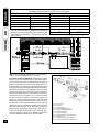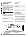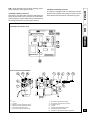
1
ZEUS Maior
Hung boilers with storage open chamber
(type C) and forced draught
User’s Manual
Instrukcja obslugi
Installer
Libro de instrucciones
User
Kullanım ve bakım kılavuzu
Technician
Manual de instruções
Návod pro obsluhu a montáz
Dear Customer,
Congratulations on your purchase of a high quality Immergas product designed to ensure prolonged comfort and safety. As an Immergas customer you can count on a professional Authorised
Service Centre, professional personnel to guarantee constant efficiency of your boiler.
Read the following pages carefully as they contain important information on the correct use of your
boiler, observe all instructions to make the most of Immergas products.
Contact our local Authorised Service Centre as soon as possible to request the preliminary test
(required to validate the guarantee). Our technician will verify correct operating conditions, make
the necessary adjustments and will show you how to use the appliance correctly.
In the event of problems or maintenance requirements, contact our Authorised Service Centre to
ensure use of original spare parts and professional service.
General warnings
This instruction booklet is considered an integral part of the product and must be delivered to the
user with the appliance.
Store the booklet in a safe place and read carefully before using the appliance as it contains
important information to ensure safe installation operation and maintenance.
Installation and maintenance must be performed in compliance with current standards according
to the manufacturer’s instructions and by qualified personnel'.
Incorrect installation can cause damage or physical injury and the manufacturer declines all liability
for failure to observe instructions and standards. Maintenance must be performed by qualified
personnel. In this case, an Authorised Immergas Service Centre represents a guarantee of professional and qualified services.
The appliance must be used according to the applications as specified in design. Any other use is
considered improper and therefore hazardous.
The manufacturer declines all contractual or non-contractual liability for damage caused by incorrect installation or operation and failure to observe relative instructions.
INDEX
INSTALLER
1
1.1
1.2
1.3
1.4
1.5
1.6
1.7
1.8
1.9
1.10
1.11
1.12
1.13
1.14
Biler installation ....................................................................................................................................... 3
Warnings. ................................................................................................................................................ 3
Main dimensions. .................................................................................................................................... 3
Connection unit (supplied standard with the boiler). ............................................................................... 4
Installing air intake and flue exhaust terminals. ...................................................................................... 5
Flue exhaust via flues. .......................................................................................................................... 13
Ducting flues. ........................................................................................................................................ 14
Chimneys/flues. .................................................................................................................................... 14
System filling. ........................................................................................................................................ 14
Gas system start-up. ............................................................................................................................. 14
Boiler start-up (ignition). ........................................................................................................................ 15
Circulating pump. .................................................................................................................................. 15
Domestic hot water boiler. ..................................................................................................................... 16
Kits available on request. ...................................................................................................................... 16
Zeus Maior boiler components. ............................................................................................................. 17
USER
2
2.1
2.2
2.3
2.4
2.5
2.6
2.7
2.8
2.9
2.10
page
Uuse and maintenance instructions ...................................................................................................... 18
Free preliminary testing. ....................................................................................................................... 18
Cleaning and Maintenance. .................................................................................................................. 18
General Warnings. ................................................................................................................................ 18
Zeus Maior - Control panel. .................................................................................................................. 18
Restore heating system pressure. ........................................................................................................ 19
Draining the system. ............................................................................................................................. 19
Boiler emptying. .................................................................................................................................... 19
Anti-freeze protection. ........................................................................................................................... 19
Casing cleaning. ................................................................................................................................... 19
Decommissioning. ................................................................................................................................. 19
TECHNICIAN
3
3.1
3.2
3.3
3.4
3.5
3.6
3.7
3.8
3.9
3.10
3.11
3.12
3.13
3.14
3.15
page
page
Boiler start-up preliminary check ........................................................................................................... 20
Zeus Maior wiring diagram. ................................................................................................................... 20
Zeus Maior hydraulic diagram. .............................................................................................................. 21
Troubleshooting. ................................................................................................................................... 21
Converting the boiler to other types of gas. .......................................................................................... 22
Checks following conversion to other type of gas. ................................................................................ 22
Zeus Maior adjustments. ....................................................................................................................... 22
Zeus Maior slow ignition adjustment. .................................................................................................... 22
Pump antiblock function. ....................................................................................................................... 23
Boiler antifreeze function. ..................................................................................................................... 23
Casing removal. .................................................................................................................................... 24
Yearly appliance control and service. ................................................................................................... 25
Zeus 21 Maior series variable heat output. ........................................................................................... 26
Zeus 24 Maior series variable heat output. ........................................................................................... 26
Zeus 21 Maior technical data. ............................................................................................................... 27
Zeus 24 Maior series technical data. .................................................................................................... 28
Immergas S.p.A. declines any responsibility for printing or transcription errors, and reserves the right to make
any changes to its technical and commercial lists without prior notice.
INSTALLER
USER
1.1 Warnings.
Immergas gas appliances must be installed
exclusively by a professionally qualified and
authorized technician.
Installation must be performed in compliance with
standards UNI and CEI, current legislation and in
observance with local technical standards according
to a professional code of practice.
The following standards must be observed in
particular: UNI-CIG 7129 and 7131 and CEI 64-8 and
64-9.
Before installing the appliance, ensure that it is
delivered in perfect condition; if in doubt, contact the
supplier immediately. Packaging materials (staples,
nails, plastic bags, polystyrene foam etc.) constitute
a hazard and must be kept out of the reach of
children.
If the appliance is installed inside or between other
cabinets or furniture, ensure sufficient space for
maintenance; a clearance of 2-3 cm between the
boiler casing and the sides of the cabinet is
recommended.
Keep all flammable objects away from the appliance
(paper, rags, plastic, polystyrene, etc.).
In the event of malfunctions, faults or incorrect
operation, switch the appliance off immediately and
contact a qualified technician (e.g. from the Immergas
Service centre to ensure use of original spare parts).
Never attempt to modify or repair the appliance alone.
Failure to observe the above implies personal
responsibility and renders the guarantee null and
void.
• Installation standards: these boilers have been
designed exclusively for wall-mounted installation.
The wall surface must be smooth, without any
protrusions or dents enabling access to the rear
section. Boilers must NOT be installed on plinths
or floors (see figure).
YES
NO
Caution: installation of the boiler on the wall must
guarantee a stable and efficient support for the
generator. The plugs supplied with the appliance
ensure adequate support only if inserted correctly
(according to technical standards) in walls comprising
bricks or breeze blocks. In the case of walls made
from bricks or cavity bricks, partitions with limited
static properties, or in any case walls other than those
indicated, a static test must be carried out to ensure
adequate support. These boilers are used to heat
water to below boiling temperature in atmospheric
pressure.
They must be connected to a heating system and
domestic water circuit suitable to their performance
and capacity. These boilers cannot be installed in
bedrooms, bath and shower rooms. Neither can they
be installed in rooms with open chimneys (fireplaces)
without having their own air flow. They must also be
installed in a room where the temperature that does
not fall below 0°C.
They must not be exposed to atmospheric agents.
TECHNICIAN
1
BILER
INSTALLATION
1.2 Main dimensions.
Altezza (mm)
(mm)
LWidth
arghezza
(mm) P
rofondit(mm)
à (mm)
(mm)
Depth
Height
900
600
450
Attacchi
Connections
GAS
GAS
Key
G
R
M
S
U
E
V
IMPIANTO
SYSTEM
DOMESTIC
ACQUA
SWATER
ANITARIA
G
R
M
U
E
1/2"
3/4"
3/4"
1/2"
1/2"
- Gas supply
- System return
- System delivery
- Recycle (optional)
- Domestic hot water outlet
- Domestic water inlet
- Electrical connection
3
TECHNICIAN
USER
INSTALLER
1.3 Connection unit (supplied standard with the
boiler).
THE kit comprises:
N°2 - 3/4" telescopic fittings
(R-M)
N°1 - 1/2" telescopic fitting
(U)
N°1 - 1/2" gas fitting (G)
N°1 - 1/2" ball valve
1/2" (E)
N°3 - Ø18 copper bend
N°2 - Ø14 copper bend
N°2 - adjustable expansion
plugs
N°2 - boiler support hooks
Seals and O-Rings
Key:
G - 1/2" Gas supply”
R - 3/4" System return”
M - 3/4" System delivery”
S - Recycle 1/2" (optional)
U - 1/2" Domestic hot
water outlet”
E - 1/2" Domestic water
inlet”
V - 230V-50Hz Electrical
connection
Gas hook-up (Appliance category II2H3+). Immergas
boilers are designed to operate with the following
types of gas: natural gas (G20) and LPG. Delivery
pipelines must feature the same or larger diameters
as the 1/2"G boiler fitting.
Before hooking up the gas line, ensure that all system
fuel pipelines are perfectly clean, and remove all residue that could impair appliance efficiency.
Also check that the gas corresponds to boiler
specifications (see boiler dataplate). If the types are
different, the appliance should be converted for
operation with the specific type of gas required (see
converting the appliance for other gas types).
The gas pressure must also be checked (natural or
LPG) according to the type used in the boiler;
insufficient levels could reduce generator power and
malfunctions. Ensure that the gas valve connection
is correct as shown in the assembly sequence in the
figure.
Water connection. Before making the water
connections, all system piping must be cleaned
thoroughly to remove any residue that could impair
boiler efficiency. Water connections must be made
in a rational sequence using the couplings on the
boiler template. The boiler safety valve outlet must
be connected to a discharge funnel. Otherwise, the
manufacturer declines any responsibility in case of
flooding if the drain valve cuts in.
4
Key
1
2
3
4
5
6
- Gas valve
- Nitrile O-ring
- Brass washer
- Flexible brass ring
- Nut
- Gas pipe
Electrical Connection. The Zeus Maior boiler is
designed with IPX4D protection rating. Electrical
safety of the unit is guaranteed only when it is
correctly connected to an efficient earthing system
as specified by current safety regulations.
Caution: Immergas S.p.A. declines any responsibility
for damage or physical injury caused by failure to
connect the boiler to an efficient earthing system or
failure to observe CEI reference standards.
Also ensure that the electrical installation
corresponds to maximum absorbed power
specifications as shown on the boiler dataplate.
Boilers are supplied complete with an “X” type power
cable without plug.
The power cable must be connected to a 230V-50Hz
mains supply with the correct pole sequence L-N and
earth connection
; the mains power supply must
also be equipped with a multi-pole circuit breaker with
contact opening gap of at least 3 mm. In the event of
power cable replacement, contact an Authorized
Immergas Service Centre for assistance.
The power cable must be laid as shown in the figure
on page 5.
In the event of mains fuse replacement on the control
card, use a 2A quick blow fuse. For the main power
supply to the appliance, never use adapters, multiple sockets or extension leads.
N.B.: when connecting the appliance, if the correct
L-N polarity is not followed, the boiler does not detect
the flame and inhibits lighting. Also whenever L-N
polarity is not followed, if the neutral is live with
residual voltage over 30V, the boiler will probably
operate just the same (but only temporarily). Measure
voltage with suitable instruments, without using a
phase screwdriver. If the electrical supply is of the
230 V Phase-Phase type, to ensure the same safe
conditions as those existing in case the boiler is fed
with a Phase-Neutral supply, install an adapter kit
for Phase-Phase supplies, available on request.
Contact an Authorized Immergas Service Centre for
installation of the kit.
POWER
CABLE
1.4 Installing air intake and flue exhaust terminals.
Immergas supplies various solutions separately from
the boiler for the installation of air intake and flue
extraction, fundamental for boiler operation.
N.W.: The boiler must be installed exclusively with
an original Immergas air intake and flue extraction
system as specified by standards UNI 7129. This system is identifiable by a special and distinctive marking.
The flue ducts have not to be near or in contact with
inflammable materials, and they have not to pass
through buildings and walls made of inflammable
materials.
The types of terminals available from Immergas comprise:
• Concentric horizontal intake and exhaust kit.
Installation of this kit must be in compliance with
technical standards UNI 7129, and D.P.R. 412/
93, as amended by D.P.R. 551/99 and by standards
in local building regulations and subsequent
amendments. D.P.R. 412 as amended by D.P.R.
551, restricts use of this type of system exclusively
to the following cases:
• Separator kit (Ø 80/80). This kit enables air intake
to outside the building and flue exhaust via a flue
(see page 11).
The innermost duct is used for flue exhaust to the
flue and the outermost duct is used for air intake
from outside the building. Both ducts can be routed
in any direction (see page 11), except for the
insulated separator kit Ø 80/80 that with the
standard components cannot start with crossed
ducts.
• Resistance factors and equivalent lengths. Each
flue extraction system component is designed with
a resistance factor based on preliminary tests and
specified in the table below. The resistance factor
for individual components does not depend either
on the type of boiler on which it is installed or the
actual dimensions. It is based on the temperature
of fluids conveyed through the ducts and therefore
varies according to applications for air intake or
flue exhaust. Each component has a resistance
corresponding to a specific length in metres of pipe
with the same diameter; the so-called equivalent
length, based on the ratio between different resistance factors, for example : Ø80 90° bend; resistance factor on intake 5; 1-metre Ø80 pipe; resistance factor on intake 2.3; equivalent length of 90°
Ø80 bend = 5: 2.3 = 2.2 m of Ø80 pipe on intake.
In the same way each component has a resistance
factor corresponding to a specific length in metres
of a pipe with a different diameter, for example a
concentric 90° bend Ø60/100 Resistance Factor
21; pipe Ø80 m1 on exhaust, Resistance Factor =
3; Equivalent length of 90° bend Ø60/100 = 21 : 3 =
7 m of Ø80 pipe on exhaust. All boilers have a maximum resistance factor based on testing at 100. The
maximum admissible resistance factor corresponds
to the resistance detected with the maximum admissible pipe length with each type of Terminal Kit
installed. This information enables calculations to
verify the possibility of various configurations of flue
extraction systems.
INSTALLER
• Concentric vertical air intake and exhaust kit. This
terminal enables vertical air intake and flue exhaust
directly outside the building (see page 10).
USER
Caution: Make sure the thermostat contact is of the
“clean” type, i.e. independent of the mains voltage,
otherwise the electronic adjustment board will be
damaged. Boiler pipelines must never be used to
earth the electrical or telephone lines. Ensure
elimination of this risk before making the boiler
electrical connections.
left-hand outlet and front outlet as required (see
page 8).
TECHNICIAN
On/Off room thermostat electrical connection.
On/Off. Connect the thermostat or On/Off Timerthermostat to terminals 34 and 35, eliminating jumper
P1. It must have exclusively Class II (standard EN
60335-1) electrical isolation, see the wiring diagram
on page 20. The room thermostat contact, after
connection, works at mains voltage and must be able
to commutate a minimum current of 0.8A.
- “installation of heat generators in buildings
composed of a single unit”;
- “standard replacement of individual heat generator
appliances”.
This terminal enables air intake and exhaust of flues
directly outside the building. The horizontal kit can
be installed with a rear outlet, right-hand outlet,
5
TECHNICIAN
USER
INSTALLER
Resistance Factors and Equivalent Lengths.
DUCT TYPE
Concentric pipe Ø 60/100 1 m
90° bend concentric Ø 60/100
45° bend concentric Ø 60/100
Terminal complete with concentric horizontal
intake-exhaust Ø 60/100
Terminal complete with concentric horizontal
intake-exhaust Ø 60/100
Concentric pipe Ø 80/125 m 1
90° bend concentric Ø 80/125
45° bend concentric Ø 80/125
Resistance
Factor
(R)
Equivalent length in
metres of concentric
pipe Ø 60/100
Intake
and
exhaust
16.5
m 1
Intake
and
exhaust
21
m 1,3
Intake
and
exhaust
16.5
m 1
Intake
and
exhaust
46
Intake
and
exhaust
32
Intake
and
exhaust
6
Intake
and
exhaust
7.5
Intake
and
exhaust
6
m 2,8
m 1,9
m 0,4
Equivalent length in
metres of concentric
pipe Ø 80/125
m 2,8
m 3,5
m 2,8
Exhaust
5.5 m
Intake
9.1m
Exhaust
7.0m
Intake
m 7.1m
Exhaust
m 5.5m
m 7,6
Exhaust
m 15m
Intake
m 14m
m 5,3
m 1,0
Exhaust
10.6m
Intake
2.6m
Exhaust
2.0m
m 0,5
m 0,4
m 1,3
m 1,0
Intake
3.3m
Exhaust
2.5m
Intake
2.6m
Exhaust
2.0m
Intake
14.3m
Intake
and
exhaust
33
6
Intake
7.1m
Intake
m 20m
Terminal complete with concentric vertical intakeexhaust Ø 80/125
Terminal complete with concentric vertical intakeexhaust Ø 80/125
Equivalent length in
metres of pipe Ø 80
Intake
and
exhaust
26.5
m 2,0
m 5,5
Exhaust
11.0m
Intake
11.5m
m 1,6
m 4,4
Exhaust
8.8m
Terminal complete with concentric horizontal
intake-exhaust Ø 80/125
Concentric adapter from Ø 60/100
to Ø 80/125 with condensate collector
Concentric adapter from
Ø 60/100 to Ø 80/125
Pipe Ø 80 m 1
(with or without insulation)
Complete intake terminal Ø 80 m 1
(with or without insulation)
Intake terminal Ø 80
Exhaust terminal Ø 80
90°bend Ø 80
45° bend Ø 80
Sdoppiato parallelo Ø 80
da Ø 60/100 a Ø 80/80
Intake
and
exhaust
39
2.3 m
6.5 m
Equivalent length in
metres of pipe
Ø 80
Intake
16.9 m
Exhaust
13 m
Intake
and
exhaust
34
2.0 m
Intake
and
exhaust
13
0.8 m
Intake
and
exhaust
2
Equivalent length in
metres of concentric
pipe Ø 80/125
5.6 m
2.2 m
Intake
14.8 m
Exhaust
11.3 m
Intake
5.6 m
Exhaust
4.3 m
Intake
0.8 m
Exhaust
0.6 m
0.1 m
0.3 m
0.1 m
0.4 m
0.2 m
0.5 m
Intake
5
0.3 m
0.8 m
Intake
2.2 m
Intake
3
0.2 m
0.5 m
Intake
1.3 m
Exhaust
2.5
Intake
5
Exhaust
6,5
Intake
3
Exhaust
4
Intake
and
exhaust
8.8
0.1 m
0.4 m
0.3 m
0.8 m
0.4 m
1.1 m
0.2 m
0.5 m
Exhaust
0.8 m
Intake
2.2 m
Exhaust
2.1 m
Intake
1.3 m
0.2 m
0.6 m
0.5 m
1.5 m
Intake
2,3
Exhaust
3
Terminal complete with concentric vertical intakeexhaust Ø 60/100
Intake
and
exhaust
41.7
USER
Terminal complete with concentric horizontal
intake-exhaust Ø 80/125
Equivalent length in
metres of concentric
pipe Ø 60/100
TECHNICIAN
DUCT TYPE
Resistance
factor
(R)
INSTALLER
Resistance Factors and Equivalent Lengths.
Intake
1.0 m
Exhaust
1.0 m
Exhaust
1.3 m
Intake
3.8 m
Exhaust
2,9 m
Intake
18 m
2.5 m
7 m
Exhaust
14 m
7
INSTALLER
Diaphragm installation. To ensure correct operation of the boiler, a diaphragm (see figure) must be
installed on output of the sealed chamber before the
intake and exhaust duct. Selection of a suitable diaphragm depends on the type of ducting used and
maximum length: calculations can be made using
the values in the tables:
TECHNICIAN
USER
DIAPHRAGM
8
N.W.: Diaphragms are supplied as standard with the
boiler.
DIAPHRAGM
Duct length in metres
Ø 60/100 horizontal
Ø 44
Da 0 a 0,5
Ø 47
Da 0,5 a 1,5
NONE
Oltre 1,5
DIAPHRAGM
Duct length in metres
Ø 60/100 vertical
Ø 44
Da 0 a 3
Ø 47
Da 3 a 4
NONE
Oltre 4
DIAPHRAGM
*Duct length in metres
Ø 80 horizontal duct with two
bends
Ø 44
Da 0 a 17
Ø 47
Da 17 a 24
NONE
Oltre 24
* The values for maximum length are considered with
1 metre of exhaust pipe and the remaining on intake.
DIAPHRAGM
*Duct length in metres
Ø 80 vertical duct without
bends
Ø 44
Da 0 a 22
Ø 47
Da 22 a 29
NONE
Oltre 29
DIAPHRAGM
Duct length in metres
Ø 80/125 horizontal
Ø 44
Da 0 a 1
Ø 47
Da 1 a 3
NONE
Oltre 3
DIAPHRAGM
Duct length in metres
Ø 80/125 vertical
Ø 44
Da 0 a 5
Ø 47
Da 5 a 8
NONE
Oltre 8
Horizontal intake-exhaust kit Ø 60/100. Kit
assembly: install the bend with flange (2) on the
innermost hole of the boiler taking care to insert the
seal (1) and tighten with the screws supplied in the
kit Join the male end (smooth section) of terminal
pipe (3) to the female section (with lip-seals) of bend
(2) to the end stop and ensure that the internal and
external washers are fitted to achieve perfect sealing
of all couplings.
The kit comprises:
N°1 - Seal (1)
N°1 - Concentric 90° bend
(2)
N°1 - Intake/exh.. concentric
pipe Ø60/100 (3)
N°1 - Internal washer (4)
N°1 - External washer (5)
• Snap-fit couplings of concentric pipes or extensions
and elbow fittings Ø60/100. To install snap-fit
extensions with other elements of the boiler
assembly, proceed as follows: fit the concentric pipe
or elbow with the male section (smooth) on the
INSTALLER
female section (with lip seal) to the end stop on the
previously installed to ensure sealing efficiency of
the coupling.
The horizontal intake-exhaust kit Ø 60/100 can be
installed with a rear, right-hand, left-hand, or front
outlet as required.
USER
Connection with N°1 extension. Distance between
vertical boiler axis and external wall: 1855 mm.
Connection with N°2 extensions. Distance between
vertical boiler axis and external wall: 2805 mm.
• Application with lateral outlet. Using the horizontal
intake-exhaust kit only, without the special
extensions, enables routing through a wall
thickness of 722 mm with the left-hand outlet and
488 with the right-hand outlet.
• Extensions for horizontal kit. The horizontal intakeexhaust kit Ø 60/100 can be extended up to a max.
horizontal distance of 3000 mm including the grille
terminal and excluding the concentric bend on
output of the boiler. This configuration corresponds
to a resistance factor of 100. In this case special
extensions must be requested.
Horizontal intake-exhaust kit Ø 80/125. Kit
assembly: install the bend with flange (2) on the
innermost hole of the boiler taking care to insert the
seal (1) and tighten with the screws supplied in the
kit Fit the adapter (3) with the male section (smooth)
in the female section of the bend (2) (with lip seal) to
the end stop. Fit the concentric terminal Ø 80/125
(4) with the male section (smooth) in the female
section of the adapter (3) (with lip seals) to the end
stop, ensuring that the internal and external washers
are fitted to ensure sealing efficiency of all couplings.
TECHNICIAN
• Application with rear outlet. The 970 mm pipe length
enables partial routing through a maximum
thickness of 673 mm. Normally the terminal should
be shortened. Calculate the distance by adding the
following: Part thickness + internal protrusion +
external protrusion. Minimum protrusion values are
given in the figure below.
The kit comprises:
N°1 - Seal (1)
N°1 - Concentric bend
Ø 60/100 (2)
N°1 - Adapter Ø 60/100 for Ø
80/125 (3)
N°1 - Concentric int/exh
bend Ø 80/125 (4)
N°1 - Internal washer (5)
N°1 - External washer (6)
• Snap fit extension pipe fittings and concentric
elbows Ø 80/125. To install snap-fit extensions with
other elements of the boiler assembly, proceed as
follows: fit the concentric pipe or elbow with the
male section (smooth) on the female section (with
lip seals) to the end stop on the previously installed
element to ensure sealing efficiency of the coupling.
9
INSTALLER
Normally the horizontal intake/exhaust kit Ø 80/125
is used in the event of using particularly long
extensions; the kit Ø 80/125 can be installed with a
rear, right-hand, left-hand or front outlet.
• Extensions for horizontal kit. The horizontal intake/
exhaust kit Ø 80/125 can be extended up to a
maximum horizontal length of 7300 mm including
the terminal grille and excluding the concentric
bend on output of the boiler and the adapter Ø 60/
100 in Ø 80/125 (see figure). This configuration
corresponds to a resistance factor of 100. In this
case special extensions must be requested.
TECHNICIAN
USER
Caution: if the exhaust terminal and/or extension
concentric pipe needs shortening, consider that the
internal duct must always protrude by 5 mm with
respect to the external duct.
N.B.: when installing the ducts, a section clamp
with pin must be installed every 3 metres.
• External grille. The intake/exhaust terminal models
Ø 60/100 and Ø 80/125, if correctly installed, blend
with external building aesthetics. Ensure that the
silicon washer is fitted snugly against the external
wall.
N.B.: for safety purposes, do not totally or partially
obstruct the boiler intake/exhaust terminal even
temporarily.
10
Vertical kit with aluminium tile Ø 80/125. Kit
assembly: install the concentric flange (2) on the
innermost hole of the boiler taking care to insert the
seal (1) supplied with the kit and tighten by means of
the screws supplied with the boiler. Fit the male
section (smooth) of the adapter (3) coin the female
section of the concentric flange (2). Installing the
imitation aluminium tile. Replace the tile with the
aluminium sheet (5), shaping it to ensure off-flow of
rainwater. Position the fixed half-shell (7) on the
aluminium tile and insert the intake/exhaust pipe (6).
Fit the concentric terminal Ø 80/125 (6) with the male
section (smooth) in the female section of the adapter
(3) (with lip seals) to the end stop, ensuring that the
washer (4) is fitted to ensure sealing efficiency of all
couplings.
The kit comprises:
N°1 - Seal (1)
N°1 - Female concentric
flange (2)
N°1 - Adapter Ø 60/100 for Ø
80/125 (3)
N°1 - Washer(4)
N°1 - Aluminium tile (5)
N°1 - Int./Exh. concentric pipe
Ø 80/125 (6)
N°1 - Fixed half-shell (7)
N°1 - Mobile half-shell (8)
• Snap fit extension pipe fittings and concentric
elbows. To install snap-fit extensions with other
elements of the boiler assembly, proceed as
follows: fit the concentric pipe or elbow with the
male section (smooth) on the female section (with
lip seals) to the end stop on the previously installed
element to ensure sealing efficiency of the coupling.
Caution: if the exhaust terminal and/or extension
concentric pipe needs shortening, consider that the
internal duct must always protrude by 5 mm with
respect to the external duct.
This specific terminal enables flue exhaust and air
intake in a vertical direction.
N.B.: the vertical kit Ø 80/125 with aluminium tile
enables installation on terraces and roofs with
maximum gradient of 45% (24°) and the height
between the terminal cap and half-shell (374 mm)
must be strictly observed.
This vertical kit configuration can be extended to a
maximum length of 12200 mm in a vertical straight
route, including the terminal (see figure below). This
configuration corresponds to a resistance factor of
100. In this case specific extensions must be
requested.
Terminal Ø 60/100 can also be used for vertical
exhaust, in conjunction with concentric flange code
no. 3.011141 (sold separately). Height between the
terminal cap and half-shell (374 mm) must be strictly
observed (see drawing below).
This vertical kit configuration can be extended to a
maximum length of 4700 mm in a vertical straight
line, including the terminal (see figure below).
INSTALLER
TECHNICIAN
• Installation clearances. The following figure shows
the minimum installation clearances for the terminal
separator kit Ø 80/80 in maximum admissible
conditions.
USER
• Snap fit extension pipe fittings and elbows. To install
snap-fit extensions with other elements of the boiler
assembly, proceed as follows: fit the pipe or elbow
with the male section (smooth) on the female
section (with lip seals) to the end stop on the
previously installed element to ensure sealing
efficiency of the coupling.
Max Lenght 4700 mm
Max Lenght 12200 mm
couplings.
Separator kit Ø 80/80. The separator kit Ø 80/80,
enables the division of the flue exhaust pipes and air
intake pipes according to the diagram shown in the
figure.
Combustion products are expelled from duct (A). Air
is taken in through duct (B) for combustion. Both
ducts can be routed in any direction.
A=EX
HAU
ST
B=IN
The kit comprises:
N°1 Seal (1)
N°1 - Flange seal (2)
N°1 - Female intake flange
(3)
N°1 - Female exhaust
flange (4)
TAKE
N°2 - 90° bend Ø 80 (5)
N°1 - Intake terminal Ø 80
(6)
N°2 - Internal washers (7)
N°1 - External washer (8)
N°1 - Exhaust pipe Ø 80 (9)
• Assembly of separator kit Ø 80/80. Install flange
(4) on the internal hole of the boiler taking care to
insert the seal (1) supplied with the kit and tighten
by means of the screws on the boiler. Remove the
flat flange on the outermost hole and replace with
flange (3) inserting seal (2) already fitted on the
boiler and tighten with the screws supplied. Joins
bends (5) with the male section (smooth) in the
female section of the flanges (3 and 4). Fit the
intake terminal (6) with the male section (smooth)
in the female section of the flange (5) to the end
stop with the internal and external washers
inserted. Join the exhaust pipe (9) with the male
section (smooth) in the female section of the bend
(5) to the end stop ensuring that the internal washer
is fitted and to ensure sealing efficiency of the
• Extensions for separator kit Ø 80/80. The maximum
straight length (without bends) on a vertical route,
for intake and exhaust pipes Ø80 is 41 metres, 40
of which on intake and 1 on exhaust. This total
length corresponds to a resistance factor of 100.
The total effective length, obtained by adding the
length of intake and exhaust pipes Ø 80 must not
exceed the maximum values specified in the table
below. If you need to use accessories or mixed
components (for instance, passing from separator
Ø 80/80 to a concentric pipe), it is possible to
calculate the maximum extension by using a factor
of resistance for each component or its equivalent
length. The total of the resistance factors must not
exceed 100.
• Temperature drops in flue ducts. To avoid the
problem of flue condensation in the exhaust pipe
Ø 80, due to cooling through the walls, the length
of the duct must be restricted to within 5 metres. If
longer distances have to be covered, use pipe
diameters Ø 80 with insulation (see insulated
separator kit Ø 80/80).
11
NON-INSULATED DUCT
Intake (metres)
Exhaust (metres)
1
36.0*
34.5*
2
33.0*
3
32.0*
4
30.5*
5
* The intake duct can be increased by 2.5 metres if
the bend on exhaust is eliminated, 2 metres if the
intake bend is eliminated or 4 metres of both bends
are removed.
INSULATED DUCT
Exhaust (metres)
Intake (metres)
29.5*
6
7
28.0*
26.5*
8
25.5*
9
10
24.0*
22.5*
11
21.5*
12
TECHNICIAN
USER
INSTALLER
Maximum effective lengths
(including intake terminal with grille and two 90° bends)
N.B.: when installing the Ø 80 ducts, a section clamp
with pin must be installed every 3 metres.
Insulated separator kitØ 80/80. Kit assembly: install
flange (4) on the central hole of the boiler taking
care to insert the seal (1) supplied with the kit and
tighten by means of the screws on the boiler. Remove
the flat flange on the outermost hole and replace with
flange (3) inserting seal (2) already fitted on the boiler
and tighten with the screws supplied. Insert and slide
cap (6) onto bend (5) on the male section (smooth)
and join bends (5) with the male section (smooth in
the female section of flange (3). Fit bend (10) with
the male section (smooth) in the female section of
flange (4). Join the intake terminal (7) with the male
section (smooth) in the female section of bend (5) to
the end stop, ensuring that washers (8) are inserted
to achieve correct installation between the pipe and
wall and fit the end cap (6) on terminal (7). Join the
exhaust pipe (9) with the male section (smooth) in
the female section of the bend (10) to the end stop,
ensuring that the washer (8) is already inserted for
correct installation between the pipe and flue.
12
A=IN
TAKE
B=EX
HAU
ST
The kit comprises:
N°1 - Seal (1)
N°1 - Flange seal (2)
N°1 - Female intake flange (3)
N°1 - Female exhaust flange (4)
N°1 - 90° bend Ø 80 (5)
N°1 - Pipe end cap (6)
N°1 - Insulated intake terminal Ø 80 (7)
N°3 - Washers (8)
N°1 - Insulated exhaust pipe Ø 80 (9)
N°1 - Concentric 90° bend Ø 80/125 (10)
the flange must be inserted to the end stop on the
flue extraction flange to ensure that the height of
the two intake and exhaust outlets is aligned.
TECHNICIAN
USER
• Insulation of separator terminal. In the event of
problems of condensation of flues inside the exhaust pipes or on the outside surface of the intake
pipes, on request Immergas supplies insulated intake and exhaust pipes. Insulation may be necessary on exhaust pipes due to excessive drops in
temperature of flues during conveyance from the
boiler and on the intake pipes as air on input (cold)
may cause the external pipe temperature lower
than the dew point of the ambient air. The figures
below illustrate different applications of insulated
pipes.
Insulated pipes comprise an internal Ø 80 concentric pipe and a Ø 125 external pipe with static air
jacket. Technically it is not possible to start with
both Ø 80 elbows insulated as clearances will not
allow this type of installation. However an insulated
elbow can be used by selecting either the intake
or exhaust pipe. If an insulated intake pipe is used,
• Temperature loss in insulated ducting. To avoid the
problem of flue condensation in insulated exhaust
Ø 80 pipes, due to cooling via the wall, the exhaust pipe length must be restricted to 12 metres.
The figure above illustrates a typical insulation application in which the intake pipe is short and the
exhaust pipe very long (over 5 m). The entire intake pipe is insulated to prevent condensation of
humid air in the boiler environment in contact with
the cooled pipe conveying cool outdoor air. The
entire exhaust pipe is insulated with the exception
of the elbow on output of the splitter, to reduce heat
dispersion from the duct and prevent formation of
flue condensate.
N.W.: when installing the insulated ducts, a section clamp with pin must be installed every 2 metres.
INSTALLER
• Snap fit extension pipe fittings and elbows. To install snap-fit extensions with other elements of the
boiler assembly, proceed as follows: fit the concentric pipe or elbow with the male section (smooth)
on the female section (with lip seal) to the end stop
on the previously installed to ensure sealing efficiency of the couplings.
1.5 Flue exhaust via flues.
Flue exhaust does not necessarily have to be
connected a branched type traditional flue. Flue
exhaust can be connected to a special LAS type
multiple flue. Flues must be specially designed
according to specifications in the standard UNI-CIG
10641 by qualified professional personnel.
Chimney or flue sections for connection of the
exhaust pipe must comply with requirements as laid
down in standards UNI-CIG 7129 and UNI-CIG
10641.
13
INSTALLER
USER
TECHNICIAN
1.6 Ducting flues.
With a specific “ducting system” it is possible to reuse
existing flues, chimneys and technical slots to
discharge the products of combustion of the boiler.
Ducting requires using ducts declared to be suited
for the purpose by the manufacturer, following the
installation and user instructions, provided by the
manufacturer, and the requirements of the UNI 10845
standard.
1.7 Chimneys/flues.
General notes A chimney/flue used to exhaust
combustion products must be designed as follows:
- ducting must ensure sealing of combustion
products, be waterproof and insulated;
risk of counterpressure that prevents the free release
of combustion products into the atmosphere.
Therefore always observe the minimum heights
indicated in the figures in standards UNI 7129.
Positioning the draft terminals. Draft terminals
must:
- be installed on external perimeter walls of the
building;
- be positioned (see figure) according to the
minimum distances specified in current technical
standards; in particular according to paragraph
4.4.2.3 of standard UNI 7129 and subsequent
amendments and integrations.
- construction in incombustible material suitable to
resist normal mechanical stress, heat and action
of combustion products or condensation;
- ducting routed vertically without reductions/
throttles;
- adequate insulation to avoid condensation or
cooling of flue gas, in particular if installed outside
the building or in rooms without heating;
- be adequately spaced, or, be fitted with an air jacket
for insulation from zones with combustible and/or
easily flammable materials;
- installation of a solid materials collection unit below
the first flue channel at a height of at least 500mm,
fitted with a metal airtight door;
- designed with an internal circular, square or
rectangular section (in that latter two cases with
rounded angles with a radius no less than 20 mm).
Hydraulically equivalent sections are also admitted;
- installation of a chimney terminal at the top of the
flue in compliance with specifications below; if there
is no chimney terminal, it is anyhow necessary to
comply with standards UNI 10641.
- without mechanical suction devices installed at the
top of the duct;
- in flues routed inside or against inhabited buildings,
there must be no risk of pressure surges.
Chimney caps. These devices are installed on single
or multiple flues. These devices are installed to facilitate dispersion of combustion products also in
adverse weather conditions and prevent deposit of
foreign matter. Chimney caps must meet the following
requirements:
- useful output section no less than double that of
the flue/chimney;
- suitably designed to prevent penetration of rain or
snow in the flue/chimney;
- designed to ensure constant exhaust of combustion
products with any direction or angle of wind.
14
The outlet height, corresponding to the height of the
top of the flue/chimney, regardless of chimney caps,
must be outside the “backflow zone”, to avoid the
Fumes exhaust on natural draught appliances in
open top closed environments. In spaces closed
on all sides with open tops (ventilation pits, light wells,
inner courtyards, etc.), direct discharge of fumes is
allowed for natural or forced draught gas appliances
with a heat output from 4 to 35 kW, provided the
specifications of current technical standards are
complied with (UNI 7129 par. 4.7).
1.8 System filling.
Once the boiler is connected, proceed with filling the
system through the filler cock (see figure page 19).
Filling is performed at low speed to ensure release
of air bubbles in the water via the boiler and heating
system vents.
The boiler has a built-in automatic venting valve on
the expansion tank located on the side of the sealed
chamber. Check that the cap is loosened. Open the
vent valves on the radiators.
Close vent valves only when water is delivered.
Close the filling valve when the boiler pressure gauge
indicates approx. 1.2 bar.
N.B.: During these operations, turn on the circulating
pump at intervals by means of the main switch on
the control panel. Vent the circulating pump by
loosening the front cap and keeping the motor running
Retighten the cap afterwards.
1.9 Gas system start-up.
To start up the system proceed as follows:
- open windows and doors;
- avoid presence of sparks or naked flames;
The boiler must not be started up in the event of failure to comply with any of the above.
Preliminary boiler testing must be carried out by a
qualified technician (the Immergas authorized
Technical Assistance service is qualified to carry it
out free of charge*). The boiler guarantee is valid as
of the date of testing.
The test certificate and guarantee is issued to the
user on completion.
* N.B.: the free preliminary testing does not include
fumes analysis (where required) which is borne by
the client.
1.10 Boiler start-up (ignition).
The following conditions are required for boiler startup:
- ensure gas intake sealing efficiency with the shutoff
valves closed and subsequently open with gas
valve closed over an interval of 10 minutes in which
no gas transfer must be detected by the meter;
- ensure that the type of gas used corresponds to
boiler settings;
- switch on the boiler and ensure correct ignition;
1.11 Circulating pump.
Zeus Maior series boilers are supplied with a built-in
circulating pump with 3-position electric speed
control. The boiler does not operate correctly with
the circulating pump on first speed.
To ensure optimal boiler operation, in the case of
new systems (single pipe and modul) use the
circulating pump at maximum speed. The circulation
pump is already fitted with a capacitor.
- ensure that the gas flow rate and pressure values
correspond to manual specifications (see page 26);
- ensure that the safety device is engaged in the
event of gas supply failure and check activation
time;
- check activation of the main circuit-breaker switch
upstream of the boiler and on the unit;
USER
- check gas intake sealing efficiency with the boiler
gas shutoff valve closed, checking that there is no
gas transfer for at least 10 minutes.
INSTALLER
- check that the concentric intake/exhaust terminal
(if fitted) is not blocked.
TECHNICIAN
- vent all air from pipelines;
Head2 in mmw.g.
Head available on the Zeus 21 Maior system.
A=
B=
B
A
C=
D=
D
Head available on third speed setting
Head available on second speed
setting
Head available on third speed setting
with by-pass (optional) inserted
Head available on second speed
setting with by-pass (optional) inserted
C
Flow rate Litres/h
Head2 in mmw.g.
Head available on the Zeus 24 Maior system.
A=
B=
B
A
C=
D=
Head available on third speed setting
Head available on second speed
setting
Head available on third speed setting
with by-pass (optional) inserted
Head available on second speed
setting with by-pass (optional) inserted
C
D
Flow rate Litres/h
15
INSTALLER
USER
TECHNICIAN
Pump release. After a prolonged period of disuse, if
the pump is blocked, unscrew the front cap and turn
the motor shaft using a screwdriver. Take great care
during this operation to avoid damage to the motor.
1.12 Domestic hot water boiler.
The Zeus Maior boiler is of the storage type with a capacity
of 60 litres. An amply dimensioned stainless-steel coil
wound heat exchange pipe considerably reduces hot water
production times. These boilers, built with jacket, bottoms,
in stainless steel (AISI 316L), guarantee long life.
The assembly and welding (T.I.G.) construction concepts
are carefully prepared down to the smallest details in order
ensure top reliability.
The bottom inspection flange ensures a practical control
of the boiler and the coil exchange pipe as well as easy
inside cleaning.
Located on the flange cover are domestic water connection
fittings (cold inlet and hot outlet) and the Magnesium Anode
cap inclusive of the same, supplied standard to protect
the inside of the boiler against corrosion.
N.B.: Have an authorized technician (e.g. Immergas
Authorized Technical Assistance Service) check the
efficiency of the Magnesium Anode every year. The
boiler is arranged for insertion of the domestic water
recycle connection.
1.13 Kits available on request.
• Expansion tank kit for hot domestic water (on
request). If the inlet pressure exceeds 3 bar, or if
pressure reducers or check valves are installed on
the domestic hot water circuit or if the air-cushion
that forms at the top of the boiler becomes depleted,
the expansion of water contained in the boiler
subsequent heating, can cause leaks from the
safety valve. In this case an expansion vessel of
suitable capacity for the domestic water will suffice.
• Recycle kit (on request). The boiler is arranged for
application of the recycle kit. Immergas supplies a
series of fittings and connections for connecting
the boiler to the domestic circuit. The recycle kit
connection is also given on the installation
template.
• Kit of system shutoff valves (on request). The boiler
is designed for installation of system shutoff valves
for insertion on delivery and return pipelines of the
connection assembly. This kit is particularly useful
for maintenance as it allows the boiler to be emptied
without having to drain he entire system.
• Polyphosphate batching kit (on request). The
polyphosphate batching unit prevents the formation
of limescale over time and maintains constant heat
exchange conditions and production of domestic
hot water. The boiler is designed for application of
the polyphosphate batching unit.
16
• By-pass kit (on request). If zone valves are installed
on the heating system, or case of insufficient water
circulation, Immergas supplies by request the
system By-Pass Kit to be installed on the boiler
delivery
and
return
connections.
In these conditions a sufficient water flow to the
boiler is guaranteed.
The head/flow rate curve is shown in the diagram
above.
The above kits are supplied complete with
instructions for assembly and use.
TECHNICIAN
USER
INSTALLER
1.14 Zeus Maior boiler components.
Key:
1 - Intake sockets (air A) - (flue gases F)
2 - Fan safety pressure switch
3 - Heating NTC limit and regulation sensor
4 - Primary heat exchanger
5 - Combustion chamber
6 - Burner
7 - Circulating pump
8 - Gas valve
9 - Motor-operated 3-way valve
10 - Circulating pump safety flow switch
11 - System filler cock
12 - Sealed chamber
13 - Air vent valve
14
15
16
17
18
19
20
21
22
23
24
25
26
- Flue extractor hood
- Expansion tank
- Ignition/detection plugs
- Domestic circuit NTC sensor
- Overtemperature safety thermostat
- Boiler 316L stainless steel
- Domestic circuit 8 bar safety valve
- Boiler drain valve
- Flue extraction fan
- Positive signal pressure socket
- Negative signal pressure socket
- System 3 bar safety valve
- System drain cock
17
INSTALLER
USER
TECHNICIAN
2
UUSE AND MAINTENANCE
INSTRUCTIONS
2.1 Free preliminary testing.
After completion of all installation operations
(including system filling) within and no later than 30
days, contact an authorized technician (e.g.
Immergas Assistance Service).
The Immergas Service carries out preliminary testing
operations on the boiler free of charge, at the same
explaining how to use the boiler*.
N.B.: The preliminary testing by an authorized
technician is indispensable for boiler efficiency and
warranty validity; the testing ensures optimal
Immergas boiler efficiency; reliability, efficiency and
energy saving.
* N.B.: the free preliminary testing does not include
fumes analysis (where required) which is borne by
the client.
2.2 Cleaning and Maintenance.
Important: The user must have the heating system
serviced at least once a year and a combustion test
(fume test) carried out at least once every two years
in accordance with that given in the system handbook
(art. 11 D.P.R. 412/93, as amended by D.P.R. 551/
99).
This ensures that the optimal safety, performance
and operation characteristics of the boiler remain
unchanged over time.
We recommend stipulating a yearly cleaning and
maintenance contract with your zone technician.
2.3 General Warnings.
Never expose the wall-mounted boiler to direct va-
pours from a cooking surface.
Use of the boiler by unskilled persons or children is
strictly prohibited.
Never touch the flue extraction terminal (if fitted) due
to the risk of burning caused by high temperatures;
For safety purposes, check that the concentric air
intake/flue exhaust terminal (if fitted), is not blocked.
If temporary shutdown of the boiler is required, proceed as follows:
a) drain the heating system if anti-freeze is not used;
b) shut off all electrical, water and gas supplies.
In the case of work or maintenance to structures located in the vicinity of ducting or devices for flue extraction and relative accessories, switch off the appliance and on completion of operations ensure that
a qualified technician checks efficiency of the ducting
or other devices.
Never clean the appliance or connected parts with
easily flammable substances.
Never leave containers or flammable substances in
the same environment as the appliance.
• Caution: use of components involving use of electrical power requires observance of the following
rules:
- never touch the appliance with wet hands or other
parts of the body and never touch when barefoot;
- never pull electrical cables or leave the appliance
exposed to atmospheric agents (rain, sunlight, etc.);
- the appliance power supply cable must never be
replaced by the user;
- in the event of damage to the cable, switch off the
appliance and contact exclusively qualified personnel for replacement;
- in the event of prolonged periods of disuse, turn
off the main power switch.
2.4 Zeus Maior - Control panel.
18
Key:
1 - Heating temperature selector
2 - Domestic hot water temperature selector
3 - Boiler overtemperature and flue block red indicator
4 - Power On green indicator lamp
5 - 0-Domestic-Domestic and Heating-Reset switch
6 - Ignition block red indicator lamp
7 - Boiler thermometer
8 - Boiler manometer
Overtemperature block. Red indicator lamp (3)
on. If during operation a fault causes the temperature to exceed 100°C.the boiler goes on
“overtemperature” block (indicator lamp 3 on). To eliminate the “overtemperature block”, turn the main
switch (5) temporarily to the Reset position.
If this function is activated repeatedly, contact a
qualified technician for assistance (e.g. Immergas
Technical Services Centre).
Flue block - Red indicator lamp (3) on. During
operation, if the fumes exhaust duct does not work
properly the boiler goes on “flue block” (indicator light
3 on). To eliminate the “block”, turn the main switch
(5) temporarily to the Reset position.
If this function is activated repeatedly, contact a
qualified technician for assistance (e.g. Immergas
Technical Services Centre).
Ignition block - Red indicator lamp (6) on. Each
time heating or hot water production is required the
boiler lights automatically. If the boiler does not light
within 10 seconds, the boiler goes on “ignition block”
(indicator lamp 6 on).
To eliminate the “block”, turn the main switch (5)
temporarily to the Reset position.
On initial ignition or following a prolonged period of
inactivity the “ignition block” may need to be inhibited.
If this function is activated repeatedly, contact a
qualified technician for assistance (e.g. Immergas
Technical Services Centre).
Boiler shutdown. Turn off the main switch (5) by
turning it to “0” (yellow indicator lamp 4 off) and close
the gas supply valve upstream of the appliance.
Never leave the boiler switched on if left unused for
prolonged periods.
2.5 Restore heating system pressure.
Periodically check the system water pressure.
The boiler pressure gauge should read a pressure
of between 1 and 1.2 bar.
If the pressure falls below 1 bar (with the circuit cold)
INSTALLER
With the switch set to ( ) the heating control selector
(1) is inhibited, and the domestic water temperature
is regulated via selector (2).
With the switch set to (
) the heating adjustment
selector (1) is used to regulate the temperature of
radiators, while selector (2) is used for the domestic
water, turn the selectors clockwise to raise the temperature, anticlockwise to lower.
Boiler operation is now automatic. With no specific
indications, it is advisable to keep the domestic water
regulation selector (1) between the values 3 and 6,
as this position provides an optimum water temperature without forming scale.
N.B.: close the valve on completion. If pressure
values reach around 3 bar the safety valve may be
activated. In this case contact a professional
technician for assistance. In the event of frequent
pressure drops, contact qualified personnel for
assistance to eliminate system leakage.
USER
- Turn the main switch (5) to Domestic or Domestic
and Heating (indicator lamp 4 on).
restore normal pressure via the valve located at the
bottom of the boiler (see figure).
FILLER COCK
DRAIN COCK
GAS COCK
TECHNICIAN
Boiler ignition. Before lighting, make sure that the
system is full of water and that manometer (6)
indicates a pressure of 1 - 1.2 bar.
- Open the gas valve upstream of the boiler.
2.6 Draining the system.
To drain the boiler, use the special drain cock (see
figure on page 17).
Before draining, ensure that the filling valve is closed.
2.7 Boiler emptying.
To drain the boiler, use the special drain cock (see
figure above and on page 17).
N.B.: Before carrying out this operation, close the
boiler cold water inlet cock and open any domestic
circuit hot water cock to allow air to enter the boiler.
2.8 Anti-freeze protection.
The boiler comes standard with an anti-freeze
function that starts the pump and burner when the
room temperature falls below 4°C. The anti-freeze
function is guaranteed if the boiler is fully operative
and not in “block” status, and is electrically fed with
the main switch set to Summer or Winter. To avoid
continued operation in the event of prolonged
absence, the system must be drained completely or
anti-freeze substances should be added to the
heating system water. In both cases the boiler
domestic water circuit must be drained. In appliances
subject to frequent draining, the system must be
refilled with suitably treated water to eliminate
hardness that may cause limescale formation.
2.9 Casing cleaning.
Use damp cloths and neutral detergent to clean the
boiler casing. Never use abrasive or powder
detergents.
2.10 Decommissioning.
In the event of permanent shutdown of the boiler,
contact professional personnel for the procedures
and ensure that the electrical, water and gas supply
lines are shut off and disconnected.
19
INSTALLER
USER
3
of gas supply failure, as well as the relative
activation time;
BOILER START-UP
PRELIMINARY CHECK
- check activation of the main circuit-breaker switch
upstream of the boiler and on the unit;
To start up the boiler, proceed as follows:
- ensure that the declaration of conformity of
installation is supplied with the appliance;
- check that the intake and/or exhaust terminals are
not blocked;
- check gas supply circuit tightness with the 0n-Off
valves closed and subsequently open with gas valve closed; no gas transfer must be read on the
meter for 10 minutes
- ensure activation of all regulation devices;
- ensure that the type of gas used corresponds to
boiler settings;
TECHNICIAN
- ensure connection to a 230V-50Hz power mains,
correct L-N polarity and the earthing connection;
- switch on the boiler and ensure correct ignition;
- make sure the gas maximum, medium and
minimum flow-rate and pressure values correspond
to those given in the handbook on page 20.
- ensure activation of the safety pressure switch in
the event of air supply failure;
- seal the gas flow rate regulation devices (if settings
are modified);
- ensure production of hot domestic water;
- ensure tightness of water circuits.
- Check adequate ventilation and/or aeration of the
installation room.
If any checks/inspection give negative results, do not
start the boiler.
- ensure activation of the safety device in the event
Blue
Brown
Yellow/Green
Power supply
230 V
50 Hz
DOMESTIC TEMP
CONTROL
HEATING TEMP
CONTROL
CONTROL CARD
IGNITION
DETECTOR
CONTROL
UNIT
MAX HEATING
POWER
MIN HEATING
POWER
PRIMARY
SECONDARY
N.B. The Black-edged connectors
should be fitted on the
control unit
Room thermostat: the boiler is designed for
application of a Room Thermostat.
The Room Thermostat must have exclusively class II
20
Black
Orange
Red
Blue
Brown
Black
Red
Black
Violet
Violet
Orange
Blue
Brown
Blue
White
Brown
Red
Black
Red
Blue
White
White
Brown
Black
White
Red
White
Red
Black
Black
Black
Black
Blue
Brown
3.1 Zeus Maior wiring diagram.
Key:
E1-E2 - Ignition spark plugs
E3 - Detection spark plug
IG - Main switch
LD1 - Safety LEDs
LD2 - Failed lighting LED
LD3 - Mains presence LED
MOD - Modulator coil
MP - Circulator
MV - Fan
NR - Heating NTC sensor
NS - Domestic circuit NTC sensor
P1 - Ambient thermostat jumper
SP - Pump flow microswitch
SV - Air pressure microswitch
TA - Ambient thermostat On/Off
(optional)
TS - Safety thermostat
VD - Three-way diverter switch
V/G - Gas valve
electrical isolation (standard EN 60335-1).
Connect the Room Thermostat to terminals 34-35
and remove jumper P1.
INSTALLER
3.2 Zeus Maior hydraulic diagram.
R
M
G
U
E
TECHNICIAN
USER
Key:
1 - Gas valve
2 - Stainless-steel coil for boiler
3 - Magnesium anode
4 - Boiler
5 - Circulating pump
6 - Main burner
7 - Combustion chamber
8 - Primary heat exchanger
9 - Fumes extraction hood
10 - Flue extraction fan
11 - Fan safety pressure switch
12 - Sealed chamber
13 - Heating NTC limit and regulation sensor
14 - Automatic air valve
15 - Expansion tank
16 - Overtemperature safety thermostat
17 - Pump pressure microswitch
18 - Pump pressure switch
19 - System drain cock
20 - Motor-driven 3-way valve
21 - 3 bar safety valve
22 - System filler cock
23 - Domestic circuit NTC sensor
24 - 8-bar safety valve
25 - Check valve
26 - Boiler drain valve
- System return
- System delivery
- Gas supply
- Hot domestic water outlet
- Domestic water inlet
3.3 Troubleshooting.
N.B.: maintenance must be performed by qualified
personnel (e.g. Immergas Technical Service Centre).
- Smell of gas. Caused by leakage from gas circuit
pipelines. Check sealing efficiency of gas intake
circuit.
- The fan works but the discharge of ignition on the
burner ramp is not activated. The fan may start but
the safety air pressure switch does not change the
contact. In the case check the following:
1) that the intake-exhaust duct is not too long (over
admissible length).
2) that the intake-exhaust duct is not partially
blocked (on either the exhaust or intake side).
3) that the diaphragm on the flue exhaust outlet is
commensurate with the length of the intake/
exhaust ducting.
circuit or a blocked circulator. Check via the
pressure gauge that values are within admissible
limits. Check that radiator valves are not all closed
and that the circulating pump is working correctly.
- Presence of air in the system. Check opening of
the cap on the special air valve (see fig. page 17).
Ensure that system pressure and pre-charge of the
expansion vessel are within the set limits; the precharge value for the expansion vessel must be 0.8
bar, and system pressure between 1 and 1.2 bar.
- Ignition block; see pages 19 and 4 (electrical
connection).
- Boiler NTC sensor faulty. The boiler does not have
to be emptied when replacing the NTC sensor
because the sensor is not in direct contact with the
domestic hot water present inside the boiler.
4) that the sealed chamber is perfectly sealed.
5) that the fan power supply voltage is minimum
196 V.
- Irregular combustion (red or yellow flame). This
may be caused by a dirty burner, blocked reed
valve, or incorrect installation of the intake-exhaust
terminal. Clean the specified components and
ensure correct installation of the terminal.
- Frequent activation of the temperature overload
thermostat. This may be caused by lack of water
in the boiler, insufficient water circulation in the
21
INSTALLER
USER
3.4 Converting the boiler to other types of gas.
If the boiler has to be converted to a different gas
type to that specified on the dataplate, request the
relative conversion kit for quick and easy conversion.
Boiler conversion must be carried out by a qualified
technician (e.g. Immergas Technical Assistance
Service).
To convert to another type of gas the following
operations are required:
- main burner nozzle replacement;
- move jumper (13 page 23) to the correct position
for type of gas required (Natural or LPG.);
- adjustment of first slow step of burner ignition;
TECHNICIAN
• Adjustment of boiler rated heat output (see figure
on page 23).
N.B.: adjust only after setting minimum pressure
values;
- Turn the domestic hot water temperature knob
(2 page 18) to the maximum setting;
- Open the hot domestic water valve to avoid
modulation;
- adjust (eventually) heating power;
- Adjust the rated boiler heating power by means
of plastic nut (4), according to maximum pressure
values specified in the tables on page 26
according to the type of gas;
- seal the gas flow rate regulation devices (if settings
are modified).
- turn clockwise to increase heating power, and
anticlockwise to decrease.
- after completing conversion, apply the sticker,
present in the conversion kit, near the dataplate.
Using an indelible marker pen, cancel the data relative to the old type of gas.
• Heating power adjustment (see figure on page 23).
Adjust the room heating output by means of the
trimmer (12 page 23) located on the boiler
modulation electronic card, as follows:
These adjustments must be made with reference to
the type of gas used, following that given in the table
on page 26.
- close the domestic hot water cock and turn the
switch (5 page 18) to (
);
- adjustment of maximum boiler heating power;
- adjustment of minimum boiler heating power;
3.5 Checks following conversion to other type
of gas.
After ensuring that conversion was carried out with
the required nozzle diameters and that setting is to
the fixed pressure, make sure:
- that there is no flame return in the combustion
chamber;
- that the burner flame is not excessively high or low
and is stable (does not detach from burner);
- the pressure tester used for calibration is perfectly
closed and there are no leaks in the gas circuit.
N.B.: all boiler adjustment operations must be
performed by a skilled technician (e.g. from an
Immergas Technical Services Centre). Adjustment of
the burner must be carried out using a differential
“U” or digital type pressure gauge, connected to the
pressure outlet at the top of the sealed chamber (part
23 page 17) and the outlet pressure socket on the
gas valve outlet (part 6 page 23), with reference to
the pressure value specified in the table on page 26
according to the type of gas to be used with the boiler.
3.6 Zeus Maior adjustments.
• Minimum heating power adjustment (see figure
page 23). The minimum heating power is adjusted
by means of the brass screw (3) on the gas valve;
22
reconnect the modulating coil. Boiler minimum heat
output pressure must be not be adjusted to less
than the values given in the tables on page 26
according to the type of gas.
- turn off the power supply to the modulating coil
(simply detach a faston); turn the screw clockwise
to increase pressure and counterclockwise to
decrease it. On completion of adjustment,
- set the heating control selector (1 page 18) to
maximum temperature to prevent modulation;
- adjust heat output by turning the trimmer (12 page
23) on the modulation card, keeping to the values
given in the table on page 26 according to the
type of gas, for boiler variable heat output. Turn
the trimmer clockwise to increase pressure and
counterclockwise to decrease.
N.B.: to adjust the gas valve, remove the plastic
cap (9) and rotate screw (5). Afterwards, refit the
cap and screw.
N.B.: the Avio Maiorboileris equipped with
electronic modulation that adapts boiler power to
actual room heating requirements. Therefore the
boiler operates normally in a variable gas pressure
range between the minimum and maximum heating
power according to the system heat load.
N.B.: the Avio Maior boiler is produced and set to
rated power during heating.
3.7 Zeus Maior slow ignition adjustment.
After setting the minimum and maximum heating
settings for the appliance the first slow ignition step
can be set for the gas valve. Adjust by means of
trimmer (11) on the boiler electronic modulation card.
Rotate clockwise to increase pressure and
counterclockwise to decrease. To obtain slow or
gradual inter-ignition of the burner, we recommend
setting the first step for slow ignition at 25 mm H20
for boilers operating with natural gas and 70 mm
H20 for boilers operating with LPG.
3.8 Pump antiblock function.
The boiler is equipped with a function that starts the
pump at least once every 24 hours for the duration
of 30 seconds in order to reduce the risk of the pump
becoming blocked due to prolonged inactivity.
3.9 Boiler antifreeze function.
The boiler is equipped with an antifreeze function,
therefore if the system return water is below 4°C, the
boiler starts up and functions until reaching 43°C.
INSTALLER
N.B.: never fall below the minimum heating power
when setting the slow ignition values.
USER
Zeus Maior electronic card
DOMESTIC
TECHNICIAN
HEATING
Valve VK 4105 for Zeus Maior
Key:
1 - Coil
2 - Coil pin
3 - Minimum power adjustment screw
4 - Maximum power adjustment screw
5 - Protection hood fixing screw
6 - Gas valve outlet pressure socket
7
8
9
10
11
12
13
- Gas valve inlet pressure socket
- Air pressure socket hose connector
- Protection hood
- 2A fuse
- Slow ignition adjustment trimmer
- Heating adjustment trimmer
- Jumper for operation with natural gas/LPG
23
- undo the screws (2) on the top of the casing front
support sheet (see figure);
- undo the screws (3) on the bottom side of the boiler
then push upwards a little in order to free the side.
- undo the screws (1) on the bottom of the casing
front;
- pull the bottom of the casing front outwards,
pushing upwards (see figure);
TECHNICIAN
USER
INSTALLER
3.10 Casing removal.
To facilitate boiler maintenance the casing can be
completely removed as follows:
- remove the plastic lower protection grid;
2
2
3
1
24
- Clean the main burner.
- Make a visual inspection of the flue extraction hood
for wear or corrosion.
INSTALLER
3.11 Yearly appliance control and
service.
The following checks and maintenance should be
performed at least once a year.
- Clean the flue side of the heat exchanger.
- Ensure correct settings of the burner in domestic
water and heating phases.
- Check correct operation of control and adjustment
devices and in particular:
USER
- Check correct lighting and operation.
- system control thermostat intervention;
- domestic water control thermostat intervention.
- Check tightness of gas supply circuit; insert a “U”
or digital type pressure gauge in the pressure point
upstream of the gas valve and then closing the
boiler on-off valve and closing the gas valve, after
5 minutes there must be no pressure variation on
the manometer;
TECHNICIAN
- intervention of electrical main switch on boiler;
- Check intervention of the device against no gas
ionization flame control; intervention time must be
less than ten seconds;
- Visually check for water leaks or oxidation from/on
connections.
- Visually check that the water safety drain valve is
not blocked.
- Make sure that expansion tank charge, after
discharging system pressure and bringing it to the
zero (read on boiler pressure gauge), is 0.8 bar.
- Check that the system static pressure (with system
cold and after refilling the system by means of the
filler cock) is between 1 and 1.2 bar.
- Check visually that the safety and control devices
have not been tampered with and/or shorted, in
particular:
- temperature safety thermostat;
- air pressure switch.
- Check the integrity of boiler Magnesium Anode.
- Check the condition and integrity of the electrical
system and in particular:
- electrical cables must be inside the channels;
- no traces of black marking or burns.
25
TECHNICIAN
USER
INSTALLER
3.12 Zeus 21 Maior series variable heat output.
METANGAS
O (G2(G20)
0)
NATURAL
BUTANO(G30)
(G30)
BUTANE
PPROPANE
ROPANO (G31)
(G31)
NOZZLE
PO
TENZA PHEAT
OTENZA P
ORFLOW
TATA GAS P
RESSPRESSURE
.UGELLI PORTATA GAS NOZZLE
PRESSPRESSURE
.UGELLI PORTATA GAS NOZZLE
PRESSPRESSURE
.UGELLI
HEAT
GAS
GAS FLOW
GAS FLOW
TOUTPUT
ERMICA TOUTPUT
ERMICA BURNER
BRUCIA
TORE BURNER
BRUCIATORE
B
RUCIA(kg/h)
TORE BURNER
BRUCIATORE
B
RUCIA(kg/h)
TORE BURNER
BRUCIATORE
(m3/h)
BURNER
BURNER
(mbar)
(mmH20)
(kW)
(kcal/h)
(mbar)
(mmH20)
(kcal/h)
(kW)
(m3/h)
(mbar) (mmH2O)
(kg/h)
(m
bar) (mmH20)
(mmH2O)
(kg/h)
((mbar)
mbar) (m
mH2O)
21000
24,4
2,79
10,4
106
2,08
28,1
287
2,04
36,2
370
20000
23,3
2,66
9,5
96
1,98
25,3
259
1,95
32,4
330
19000
22,1
2,53
8,6
87
1,88
22,8
232
1,86
28,8
294
18000
20,9
2,40
7,7
79
1,79
20,4
208
1,76
25,6
261
17000
19,8
2,28
6,9
71
1,70
18,2
186
1,67
22,6
230
16000
18,6
2,15
6,2
63
1,60
16,2
165
1,58
19,9
203
15000
17,4
2,03
5,5
56
1,51
14,3
146
1,49
17,4
178
14000
16,3
1,90
4,8
49
1,42
12,6
129
1,40
15,2
155
13000
15,1
1,78
4,2
43
1,33
11,1
114
1,31
13,2
135
12000
14,0
1,66
3,6
37
1,23
9,8
100
1,22
11,5
117
11000
12,8
1,53
3,1
32
1,14
8,6
87
1,12
10,0
102
10000
11,6
1,41
2,6
27
1,05
7,5
77
1,03
8,8
89
9000
10,5
1,28
2,2
22
0,95
6,6
67
0,94
7,7
79
8000
9,3
1,15
1,8
18
0,86
5,9
60
0,84
7,0
71
3.13 Zeus 24 Maior series variable heat output.
NATURAL
(G20)
METANGAS
O (G2
0)
BUTANE
(G30)
BUTANO
(G30)
P
ROPANO (G31)
(G31)
PROPANE
PRESSPRESSURE
.UGELLI PORTATA GAS NOZZLE
PRESSPRESSURE
.UGELLI PORTATA GAS NOZZLE
PRESS
.UGELLI
PHEAT
OTENZA PHEAT
OTENZA GAS
PORFLOW
TATA GAS NOZZLE
PRESSURE
GAS FLOW
GAS FLOW
BRUCI(mmH20)
ATORE
B
RUCIA(kg/h)
TORE BURNER
BRUCIATORE
BRUCIA(kg/h)
TORE BURNER
BRUCIATORE
TOUTPUT
ERMICA TOUTPUT
ERMICA BURNER
BRUCI(m3/h)
ATORE BURNER
BURNER
BURNER
(mbar)
(kW)
(kcal/h)
(mmH20)
(mbar) (mmH2O)
(kg/h)
((mbar)
mbar) (mmH20)
(mmH2O)
(kg/h)
((mbar)
mbar) (m
mH2O)
(kcal/h)
(kW)
(m3/h)
26
24000
27,9
3,20
10,5
108
2,39
28,1
287
2,35
36,7
374
23000
26,7
3,07
9,8
100
2,29
25,9
264
2,26
33,7
344
22000
25,6
2,94
9,1
93
2,19
23,8
242
2,16
30,9
315
21000
24,4
2,82
8,5
87
2,10
21,7
222
2,07
28,2
288
20000
23,3
2,69
7,8
80
2,00
19,8
202
1,97
25,7
262
19000
22,1
2,56
7,2
74
1,91
18,1
184
1,88
23,3
238
18000
20,9
2,44
6,6
67
1,81
16,4
167
1,79
21,1
215
17000
19,8
2,31
6,0
61
1,72
14,8
151
1,69
19,0
194
16000
18,6
2,18
5,7
58
1,63
14,0
143
1,60
18,0
184
15000
17,4
2,06
4,9
50
1,53
11,9
121
1,51
15,3
156
14000
16,3
1,93
4,3
44
1,44
10,6
108
1,42
13,6
138
13000
15,1
1,80
3,8
38
1,34
9,4
96
1,32
12,0
122
12000
14,0
1,68
3,2
33
1,25
8,3
84
1,23
10,6
108
11000
12,8
1,55
2,7
28
1,15
7,3
74
1,14
9,2
94
10000
11,6
1,42
2,2
22
1,06
6,3
64
1,04
8,0
82
9000
10,5
1,29
1,7
17
0,96
5,5
56
0,95
7,0
71
3.14 Zeus 21 Maior technical data.
Nozzle
D
iametrodiam.
ugelli
pSupply
ressionepressure
di alimentazione
Max.
working
P
ressio
ne max pressure
d'esercizioheating
circuito circuit
riscaldamento
temp.
TMax.
empeworking
ratura ma
x d'esheating
ercizio cicircuit
rcuito riscaldamento
TAdjustable
emperaturatemp.
regolaheating
bile riscaldamento
Expansion tank total volume
Vaso d'espansione volume totale
Expansion tank preload
P
recariccontained
a vaso d'esinpaboiler
nsione
Water
C
ontenuto head
d'acquwith
a delflowrate
generato1000
re
Available
l/h
P
revalenheat
za dioutput
sponibilhot
e cowater
n portaproduction
ta 1000l/h
Useful
P
otenza termtemp.
ica utidomestic
le produziohot
ne awater
cqua calda
Adjustable
TFlow
empelimiter
ratura regolabile acqua calda sanitaria
domestic circuit
LMin.
imitapressure
tore di flus(dynamic)
so
Max.
working
P
ressio
ne min. pressure
(dinamica)domestic
circuito sacircuit
nitario
Min.
P
ressdrawing
ione maxdomestic
. d'esercizihot
o cirwater
cuito sanitario
Specific
P
ortata spdelivery
ecifica ( (∆T
∆ T 330°
0 ° C)
C)
Specific
P
ortata spdelivery
ecifica ininsecont.
rvizioduty
conti(∆T
nuo 30°
(∆ TC)
30 ° C)
Boiler
P
eso caweight
ldaia pifilled
ena
Boiler weight empty
Peso caldaia vuota
Electrical
connection
A
llacciamen
to elettrico
Nominal
A
ssorbimeabsorption
nto nominale
Installed
P
otenza eelectrical
lettrica instpower
allata
Power
P
otenzaabsorbed
assorbita dby
al circulating
circolatore pump
Power
P
otenzaabsorbed
assorbita dby
al fan
ventilatore
Equipment
P
rotezione imelectrical
pianto elesystem
ttrico approtection
parecchio
Delivery
weight
P
ortata in in
ma
ssa deof
i fufumes
mi a poat
tennominal
za nominoutput
ale
Delivery
weight
P
ortata in in
ma
ssa deof
i fufumes
mi a poat
tenmin.
za moutput
inima
CO2
Q.QNNom./Min
om./Min.
C
O2 aat
CO
0%di02
Q. Nom./Min
aQ
Nom./Min.
C
O aat0%
O2 at
NOx
0%
Q. N
Nom./Min
N
OX aat0%
di 02
O2 at
aQ
om./Min.
Temp.
fumes
at
nominal
output
Temperatura fumi a potenza nominale
Temp. fumes at min. output
Temperatura fumi a potenza minima
kW
kW
kW
kW
(kcal/h)
(kcal/h)
(kcal/h)
(kcal/h)
%
%
%
%
mm
mbar (mmH2O)
26,3 (22629)
10,9 (9335)
24,4 (21000)
9,3 (8000)
92,8
89,7
0,70/0,90
6,50/0,06
G20
G30
G31
1,30
20 (204)
0,75
29 (296)
0,75
37 (377)
bar
°C
°C
l
bar
l
kPa (mH2O)
kW (kcal/h)
°C
l/min
bar
bar
l/min
l/min
kg
kg
3
90
43 - 90
8
0,8
3,5
22,5 (2,3)
24,4 (21000)
20 - 60
10
0,1
8
15,2
11,4
134
70
V/Hz
A
W
W
W
-
230/50
0,68
140
78
35
IP44
kg/h
kg/h
%
ppm
ppm
°C
°C
USER
P
ortata terheat
micaoutput
nominale
Nominal
Min.
output
P
ortatheat
a term
ica minima
Nominal
P
otenza teheating
rmica nopower
minale(useful)
(utile)
Min.
(useful)
P
otenheating
za termicpower
a minim
a (utile)
Useful
thermal
R
endime
nto termeffic.
ico utat
ile nominal
alla potenoutput
za nominale
Useful
thermal
R
endime
nto termeffic.
ico utat
ile 30%
alcariload
co deof
l 3nominal
0% dellapower
potenza nom.
Heat loss at shell with burner On/Off
Perdita di calore al mantello con bruciatore On/Off
Heat loss at flue with burner On/Off
Perdita di calore al camino con bruciatore On/Off
INSTALLER
adjustable gas valve and on the sealed chamber positive pressure test outlet . Power data specified in the
table refer to a 1 metre intake/exhaust pipe. Gas flow
rates refer to heat power below temperature of 15°C
and at a pressure of 1013 mbar. Burner pressure
values refer to use of gas at 15°C.
G20
G30
G31
56
59
6,7/2,5
68/84
163/96
118
97
61
65
7,1/2,6
51/109
194/105
122
100
61
67
7,0/2,5
51/109
185/99
125
99
TECHNICIAN
N.W.: Pressure values specified in the table indicate
the difference of pressure values between the gas
valve outlet and the combustion chamber. Adjustments are therefore carried out with the differential
pressure gauge ( “U” or digital type) with the sensors
inserted in the test pressure outlet of the modulating
Control temperature at domestic water flow rate at 8
l/min. and input temperature of 15°C.
Flue temperature values refer to air inlet temperatures
of 15°C.
27
TECHNICIAN
USER
INSTALLER
3.15 Zeus 24 Maior series technical data.
Nominal
P
ortata terheat
mica output
nominale
Min.
output
P
ortatheat
a term
ica minima
Nominal
P
otenza teheating
rmica nopower
minale (useful)
(utile)
Min.
P
otenheating
za termicpower
a minim(useful)
a (utile)
Useful
R
endimethermal
nto termeffic.
ico utiat
le nominal
alla potenoutput
za nominale
Useful thermal effic. at 30% load of nominal power
Rendimento termico utile alcarico del 30% della potenza nom.
Heat loss at shell with burner On/Off
P
erditaloss
di cat
aloflue
re alwith
manburner
tello conOn/Off
bruciatore On/Off
Heat
Perdita di calore al camino con bruciatore On/Off
DNozzle
iametrodiam.
ugelli
pSupply
ressionepressure
di alimentazione
Max.
Pressiworking
one max pressure
d'esercizioheating
circuito circuit
riscaldamento
Max.
working
Tempe
ratura mtemp.
ax d'esheating
ercizio ccircuit
ircuito riscaldamento
Adjustable
Temperaturatemp.
regolaheating
bile riscaldamento
Expansion
Vaso d'espatank
nsiontotal
e voluvolume
me totale
Expansion
tank preload
Precarica vaso d'espansione
Water contained in boiler
Contenuto head
d'acquwith
a deflowrate
l generato1000
re l/h
Available
Prevaleheat
nza doutput
isponibihot
le cowater
n porta
ta 1000l/h
Useful
production
Potenza term
ica utidomestic
le produziohot
ne a
cqua calda
Adjustable
temp.
water
Templimiter
eratura regolabile acqua calda sanitaria
Flow
Limitapressure
tore di flus(dynamic)
so
Min.
domestic circuit
Max.
Pressiworking
one min. pressure
(dinamica)domestic
circuito sacircuit
nitario
Min.
Pressdrawing
ione maxdomestic
. d'esercizihot
o cirwater
cuito sanitario
Specific
delivery
Portata sp
ecifica ( (∆T
∆ T 30°
30 ° C)
C)
Specific
delivery
cont.
Portata sp
ecifica ininse
rvizioduty
conti(∆T
nuo 30°
( ∆ TC)30 ° C)
Boiler
Peso cweight
aldaia pfilled
iena
Boiler
weight empty
Peso caldaia vuota
mm
mbar (mm H2O)
30,3 (26030)
12,2 (10466)
27,9 (24000)
10,5 (9000)
92,2
89,8
1,1/0,85
6,7/0,06
G20
G3 0
G31
1,30
20 (204)
0,75
29 (296)
0,75
37 (377)
bar
°C
°C
l
bar
l
kPa (m H2O)
(kW) kcal/h
°C
l/min
bar
bar
l/min
l/min
kg
kg
3
90
43 - 90
8
0,8
4
29,4 (3,0)
27,9 (24000)
20 - 60
12
0,1
8
16,8
13,9
138
74
Allacciameconnection
nto elettrico
Electrical
Nominal
Assorbimeabsorption
nto nominale
Installed
Potenza eelectrical
lettrica inspower
tallata
Power
Potenzaabsorbed
assorbita by
dal circulating
circolatore pump
Power
Potenzaabsorbed
assorbita by
dal fan
ventilatore
Equipment
electrical
Protezione im
pianto elesystem
ttrico approtection
parecchio
V/Hz
A
W
W
W
-
230/50
0,76
155
90
35
IP44
Delivery
Portata ininmweight
assa deof
i fufumes
mi a poat
tennominal
za nominoutput
ale
Delivery
Portata ininmweight
assa deof
i fufumes
mi a poat
tenmin.
za moutput
inima
CO2
. NNom./Min
om./Min.
CO2 aatQQ
CO
at00%
aQ
Q. Nom./Min
Nom./Min.
CO a
% d02
i O2at
NOx
0%di02
Q. Nom./Min
NOX aat0%
O2 at
aQ
Nom./Min.
Temp. fumes at nominal output
Temperatura fumi a potenza nominale
Temp. fumes at min. output
kg/h
kg/h
%
ppm
ppm
°C
°C
Temperatura fumi a potenza minima
Control temperature at domestic water flow rate at 8
l/min. and input temperature of 15°C.
Flue temperature values refer to air inlet temperatures
of 15°C.
28
(kW) kcal/h
(kW) kcal/h
(kW) kcal/h
(kW) kcal/h
%
%
%
%
G20
G30
G31
67
71
6,5/2,3
64/104
150/83
115
85
69
79
7,2/2,4
89/112
240/108
117
83
71
79
7,0/2,4
60/130
201/102
120
92
INTERNET
http: //www.
immergas.com
IMMERGAS S.p.A. • 42041 Brescello (RE) Italy
Cod. 1.017431 Rev. 15.011378/000 - 04/01