1
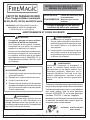
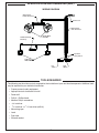
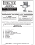
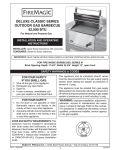
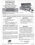
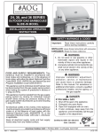
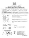
WALL VENT HOOD
For Outdoor Use Only
36-VH, 42-VH, 48-VH and 60-VH series
42-VH-6 model shown
INSTALLATION INSTRUCTIONS
AND OWNER’S MANUAL
INSTALLER: Leave these instructions with consumer.
CONSUMER: Retain for future reference.
This vent hood is for outdoor,
wall mount installation only.
Important: READ THESE INSTRUCTIONS CAREFULLY BEFORE STARTING INSTALLATION OR USE.
WARNINGS AND SAFETY CODES
CAUTION:
• This vent hood is for outdoor, wall
mount installation only.
• For General Ventilating Use Only. Do Not
Use To Exhaust Hazardous Or Explosive
Materials And Vapors!
• Observe all local codes and ordinances
when installing this appliance. If no
local codes are applicable, wire unit
in accordance with the latest National
Electrical Code, ANSI/NFPA 70, or the
Canadian Electrical Code, CSA C22.1,
whichever is applicable.
WARNING:
1. Do not store or use gasoline or other
flammable vapors and liquids in the
vicinity of the gas grill this vent hood is
installed above, or any other appliance.
2. An LP cylinder not connected for use
shall not be stored in the vicinity of the
gas grill this vent hood is installed above,
or any other appliance.
WARNING:
Improper installation, adjustment, alteration,
service, or maintenance can cause injury
or property damage. For proper installation,
refer to the installation instructions. For assistance or additional information, consult
a qualified professional installer or service
agency.
DANGER:
IF YOU SMELL GAS:
1. Shut off the gas to the grill this vent hood
is installed above.
2. Extinguish any open flame.
3. Open the lid of the grill.
4. If odor continues, keep away from the
appliances and immediately call your gas
supplier or the fire department.
All electrical outlets in the vicinity of the grill
and vent hood must be properly grounded in
accordance with local codes, or, in the absence
of local codes, with the National Electrical Code,
ANSI/NFPA 70, or the Canadian Electrical Code,
CSA C22.1, whichever is applicable.
Keep all electrical-supply cords and fuel-supply
hoses away from any heated surface.
WARNING:
To avoid the risk of property damage and/or
personal injury, installation work and electrical
wiring must be performed by a qualified
professional installer. This appliance must be
installed in accordance with this instruction.
Certified to: ANSI Z21.58b-2012
CSA 1.6b-2012
10-33
Robert H. Peterson Co. • 14724 East Proctor Avenue • City of Industry, CA 91746
REV 2 - 1502191555
1
L-C2-387
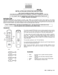
INSTRUCTIONS D'INSTALLATION ET
MANUEL DU PROPRIÉTAIRE
CAPOT DE PASSAGE DE MUR
Pour l'usage extérieur seulement
36-VH, 42-VH, 48-VH, and 60-VH série
INSTALLATEUR:
Laissez ces instructions avec
le consommateur.
CONSOMMATEUR: Maintenez pour la future
référence.
Ce capot de passage est pour extérieur,
installation de bâti de mur seulement.
IMPORTANT: LISEZ CES INSTRUCTIONS SOIGNEUSEMENT AVANT DE COMMENCER
L'INSTALLATION OU L'UTILISATION
AVERTISSEMENTS ET CODES DE SÛRETÉ
ATTENTION:
AVERTISSEMENT:
1. Ne stockez pas ou employer l'essence ou
d'autres vapeurs et liquides inflammables à
proximité du gaz grillez ce capot de passage
est installé ci-dessus, ou n'importe quel
autre appareil.
• Ce capot de passage est pour extérieur,
installation de bâti de mur seulement.
• Pour l'usage de aération général seulement.
N'employez pas pour épuiser les matériaux
dangereux ou explosifs et les vapeurs!
2. Un cylindre de LP non relié pour l'usage ne
sera stocké à proximité du gril de gaz que
ce capot de passage est installé ci-dessus,
ou d'aucun autre appareil.
• Observez tous les codes locaux et ordonnances
en installant cet appareil. Si aucun code local
ne s'applique, unité de fil selon le plus défunt
code électrique national, ANSI/NFPA 70, ou
le code électrique canadien, CSA C22.1, celui
qui s'applique.
AVERTISSEMENT:
L'installation, l'ajustement, le changement, le
service, ou l'entretien inexact peuvent causer
des dommages ou des dégats matériels. Pour
l'installation appropriée, référez-vous aux instructions d'installation. Pour l'aide ou les informations supplémentaires, consultez un installateur ou une agence de service professionnel
qualifié.
DANGER:
SI VOUS SENTEZ LE GAZ:
1. Coupez le gaz au gril que ce capot de passage
est installé ci-dessus.
2. Éteignez-vous n'importe quelle flamme nue.
3. Ouvrez le couvercle du gril.
4. Si l'odeur continue, gardez à partir des appareils
et appelez immédiatement votre fournisseur de
gaz ou les corps de sapeurs-pompierssupplier
or the fire department.
Toutes les sorties électriques à proximité du capot
de gril et de passage doivent être correctement
fondues selon des codes locaux, ou, en l'absence
des codes locaux, avec le code électrique
national, ANSI/NFPA 70, ou le code électrique
canadien, CSA C22.1, celui qui s'applique.
AVERTISSEMENT:
Maintenez tout électrique-fournissent des cordes
et carburant-fournissent des tuyaux à partir de
n'importe quelle surface heated.
Pour éviter le risque de dégats matériels et/ou de
dommage corporel, le travail d'installation et le
câblage électrique doivent être exécutés par un
installateur professionnel qualifié. Cet appareil doit
être installé selon cette instruction.
Certified to: ANSI Z21.58b-2012
CSA 1.6b-2012
10-33
Robert H. Peterson Co. • 14724 East Proctor Avenue • City of Industry, CA 91746
REV 2 - 1502191555
2
L-C2-387
CONTENTS
GETTING STARTED
IMPORTANT PRE-INSTALLATION AND SAFETY INFORMATION ............................................ 5
SPECIFICATIONS AND DIMENSIONS ................................................................................................ 6
ELECTRICAL SAFETY ............................................................................................................................. 6
TOOLS REQUIRED .................................................................................................................................... 7
REPLACEMENT PARTS LIST ................................................................................................................. 8
INSTALLATION REQUIREMENTS - FIRE MAGIC SPACER & DUCT COVER ........................ 9
INSTALLATION REQUIREMENTS - CUSTOM SPACER & SOFFIT .......................................... 10
INSTALLATION
INSTALLATION ........................................................................................................................................ 11
SPACER ................................................................................................................................................. 11
TRANSITION......................................................................................................................................... 12
WALL MOUNT BRACKET .................................................................................................................... 13
VENT HOOD......................................................................................................................................... 14
VENT PIPING ....................................................................................................................................... 15
FAN ASSEMBLY .................................................................................................................................... 16
WIRING CONNECTIONS ..................................................................................................................... 16
BAFFLE ................................................................................................................................................ 17
GREASE FILTERS ................................................................................................................................ 17
ELECTRICAL ........................................................................................................................................ 18
DUCT COVER / CUSTOM SOFFIT ..................................................................................................... 19
USE, CARE, & SERVICE
OPERATION ............................................................................................................................................... 21
VENT HOOD FANS............................................................................................................................... 21
GRILL TOP LIGHTING ........................................................................................................................ 21
SERVICING AND CLEANING .............................................................................................................. 22
REMOVE FIRE MAGIC DUCT COVER (if applicable) ...................................................................... 22
STAINLESS STEEL CARE..................................................................................................................... 22
GREASE FILTERS ................................................................................................................................ 22
FANS ...................................................................................................................................................... 22
REPLACING HALOGEN BULBS ......................................................................................................... 23
NOTES PAGE ............................................................................................................................................. 24
TROUBLESHOOTING............................................................................................................................. 25
WARRANTY .............................................................................................................................................. 26
REV 2 - 1502191555
3
L-C2-387
L'INFORMATION IMPORTANTE DE PRÉINSTALLATION ET DE SÛRETÉ
AVERTISSEMENT!
1. Lisez toutes les instructions.
2. CE CAPOT DE PASSAGE EST POUR EXTÉRIEUR, INSTALLATION DE BÂTI DE MUR SEULEMENT.
Extérieur est défini comme secteur qui a l'air illimité, s'ouvrent aux éléments à tout moment. Un
mur est défini comme côté d'un plancher et d'un toit se reliants de bâtiment.
3. L'installation, le service, et la réparation doivent être faits par un technicien qualifié de service
professionnel.
4. Cette hotte est à utiliser avec un gril à gaz seulement. Il n'est pas recommandé pour une utilisation avec un
gril à charbon (en raison de la production de chaleur plus élevé qui peut causer des dommages à la hotte).
5. Le capot de passage et le gril de gaz ne sont pas prévus pour être installés dans ou sur des bateaux ou
des camping-cars.
6. Pour se protéger contre la décharge électrique, n'immergez pas la corde ou ne branchez pas l'eau ou tout
autre liquide.
7. Débranchez de la sortie si non utilisable et avant le nettoyage. Laissez se refroidir avant de mettre dessus
ou enlever des pièces.
8. N'actionnez aucun appareil avec une corde endommagée, prise, ou après les défauts de fonctionnement
d'appareils ou avez été endommagé de toute façon. Entrez en contact avec le fabricant pour la réparation.
9. Ne laissez pas la corde toucher les surfaces chaudes.
10. N'employez pas un appareil à gaz à cuire extérieur pour des buts autres que prévu.
11. En se reliant, reliez d'abord la prise à l'appareil à gaz à cuire extérieur branchent alors l'appareil à la sortie.
12. Cet appareil doit être fondu. En cas d'un court-circuit électrique, fondre réduit le risque de décharge
électrique en fournissant un fil d'évasion pour le courant électrique. Cet appareil equipeed avec une corde
ayant un fil fondé avec une prise fondante. La prise doit être branchée à une sortie qui est correctement
installée et fondue.
13. Utilisez uniquement un correctement câblé et inspecté 120VAC (15 AMP minimum) disjoncteur
(GFCI) TERRE 3 fils récipient avec cet appareil au gaz de cuisine en plein air.
14. N'enlevez jamais la prise fondante ou l'employez avec un adapteur de 2 fourches.
15. Ne pas utiliser une rallonge. Si le cordon d'alimentation est trop court, demandez à un électricien qualifié
d'installer une prise près de l'appareil.
16. Quand la coupure ou le forage dans un mur ou un plafond, n'endommagent pas le câblage électrique et
d'autres utilités cachées.
17. Des ventilateurs canalisés doivent toujours être exhalés à l'extérieur.
18. AVERTISSEMENT : Pour réduire le risque du feu, employez seulement la canalisation en métal.
19. AVERTISSEMENT : Pour réduire le risque d'un dessus de gamme graissez le feu:
a. Ne laissez jamais les unités extérieures sans surveillance aux arrangements élevés. Tabagisme de cause
de Boilovers et débordements graisseux qui peuvent mettre à feu. Chauffez les huiles lentement sur de
bas ou moyens arrangements.
b. Toujours mettre la hotte au réglage HI lors de la cuisson à feu vif ou que vous cuisinez des mets flambés.
c. Nettoyez les ventilateurs d'aération fréquemment. On ne devrait pas permettre à la graisse de s'accumuler
sur le ventilateur ou le filtre.
d. Employez la taille appropriée de casserole. Employez toujours le cookware approprié pour la taille de
la surface à cuire.
20. N'EMPLOYEZ PAS LES COUDES 90˚ POUR CETTE INSTALLATION. N'UTILISEZ PAS UNE PAC
RESTRICTIVE D'ARRÊT POUR CETTE INSTALLATION. La tuyauterie de passage devrait être installée
aussi directement comme possible d'empêcher la contre-pression sur les ventilateurs. Mettez en
référence la section SIFFLANTE de PASSAGE de ce manuel pour des détails.
SAUF CES INSTRUCTIONS
REV 2 - 1502191555
4
L-C2-387
IMPORTANT PRE-INSTALLATION AND SAFETY INFORMATION
WARNING!
1. Read all instructions.
2. THIS VENT HOOD IS FOR OUTDOOR,WALL MOUNT INSTALLATION ONLY. Outdoor is defined
as an area that has unconfined air, open to the elements at all times. A wall is defined as a
side of a building connecting floor and roof.
3. Installation, service, and repair must be done by a qualified professional service technician.
4. This vent hood is for use with a gas grill only. It is not recommended for use with a charcoal grill
(due to higher heat output that may cause damage to the vent hood).
5. The vent hood and the gas grill are not intended to be installed in or on boats or recreational vehicles.
6. To protect against electric shock, do not immerse cord or plugs in water or other liquid.
7. Unplug from the outlet when not in use and before cleaning. Allow to cool before putting on or
taking off parts.
8. Do not operate any appliance with a damaged cord, plug, or after the appliance malfunctions or
has been damaged in any manner. Contact the manufacturer for repair.
9. Do not let the cord touch hot surfaces.
10. Do not use an outdoor cooking gas appliance for purposes other than intended.
11. When connecting, first connect plug to the outdoor cooking gas appliance, then plug appliance
into the outlet.
12. This appliance must be grounded. In the event of an electrical short circuit, grounding reduces the
risk of electric shock by providing an escape wire for the electric current. This appliance is equipped
with a cord having a grounded wire with a grounding plug. The plug must be plugged into an outlet
that is properly installed and grounded.
13. Use only a properly wired and inspected 120VAC (15 AMP minimum) Ground Fault Circuit Interrupter
(GFCI) GROUNDED 3-wire receptacle with this outdoor cooking gas appliance.
14. Never remove the grounding plug or use with an adapter of 2 prongs.
15. Do not use an extension cord. If the power cord is too short, have a qualified electrician install an
outlet near the appliance.
16. When cutting or drilling into a wall or roof, do not damage electrical wiring and other hidden utilities.
17. Ducted fans must always be vented to the outdoors.
18. WARNING: To reduce the risk of fire, use only metal ductwork.
19. WARNING: To reduce the risk of a range top grease fire:
a. Never leave surface units unattended at high settings. Boilovers cause smoking and greasy
spillovers that may ignite. Heat oils slowly on low or medium settings.
b. Always turn hood to HI Setting when cooking at high heat or when cooking flaming foods.
c. Clean ventilating fans frequently. Grease should not be allowed to accumulate on fan or filter.
d. Use proper pan size. Always use cookware appropriate for the size of the cooking surface.
20. DO NOT USE 90˚ ELBOWS FOR THIS INSTALLATION. DO NOT USE A RESTRICTIVE
TERMINATION CAP FOR THIS INSTALLATION. Vent piping should be installed as straight
as possible to prevent back-pressure on the fans. Reference the VENT PIPING section of
this manual for details.
SAVE THESE INSTRUCTIONS
REV 2 - 1502191555
5
L-C2-387
ELECTRICAL SAFETY
To protect against electric shock, do not immerse cord or plugs in water or other liquid.
Unplug from the outlet when not in use and before cleaning. Allow to cool before putting on or taking off parts.
Do not operate any outdoor cooking gas appliance with a damaged cord, plug, or after the appliance malfunctions
or has been damaged in any manner. Contact the manufacturer for repair.
Do not let the cord touch hot surfaces.
Do not use an outdoor cooking gas appliance for purposes other than intended.
When connecting, first make wire connections then plug appliance into the outlet.
Use only a properly wired and inspected 120VAC (15 AMP minimum) GFCI GROUNDED 3-wire receptacle
with this outdoor appliance.
Never remove the grounding plug or use with an adapter of 2 prongs.
Use only extension cords with a 3 prong grounding plug, rated for the power of the equipment, and approved for
outdoor use with a W-A marking.
SPECIFICATIONS AND DIMENSIONS
36-VH series
42-VH series
48-VH series
Specification
Value
Value
Value
Unit height *
18"
18"
18"
Unit width
36"
42"
48"
Unit depth
30"
30"
30"
* Height is of vent hood only (not accounting for transition).
Specification
Transition height
36-VH series
Value
10"
42-VH series
Value
10"
48-VH series
Value
10"
60-VH series
Value
18"
60"
30"
60-VH series
Value
10"
Specification
Input electrical requirements
Value
120VAC / 15 AMP minimum / 60 Hz / GFCI outlet
Fans
120 volts, 1200 CFM High Pressure Output
Power consumption
1,010 watts
Vent Hood Model
36-VH series
Designed For Use With Grills:
up to A540
42-VH series
up to (A,E)660
48-VH series
up to (A,E)790
60-VH series
up to E1060
Table 1 - Specifications Table
REV 2 - 1502191555
6
L-C2-387
SPECIFICATIONS AND DIMENSIONS (cont.)
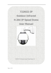
WIRING DIAGRAM
Wire harness,
blower vent hood
Power cord
Wire harness,
main vent hood
Thermostat Snap
Disc Assy
Blower Motor
600 CFM
3-position
rotary switch
Light Assy
120V 50 Watt
Fan
switch
Light
switch
TOOLS REQUIRED
The following are the minimum tools required for the installation of your vent hood components. Additional tools
may be required for your individual installation.
• Proper personal safety equipment
• Appropriate tools for electrical install
• Power drill
• Drill bit - Phillips head
• Medium Philips screwdriver
•
3/8"
nut driver
•
1/4"
nut driver or 1/4" hex driver (drill bit)
• Measuring tape
• Level
• Duct tape
• Silicone sealant
REV 2 - 1502191555
7
L-C2-387
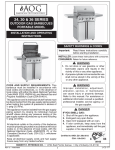
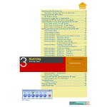
REPLACEMENT PARTS LIST
36-VH-6
Item
Description
42-VH-6
48-VH-6
60-VH-6
Part No.
Qty.
Part No.
Qty.
Part No.
Qty.
Part No.
Qty.
VH-11
1
VH-11
1
VH-11
1
VH-11
1
VH-17-6
1
VH-19-6
1
VH-22-6
1
VH-21-6
1
VH-36-01-6
1
VH-42-01-6
1
VH-48-01-6
1
VH-60-01-6
1
VH-12-6
2
VH-12-6
2
VH-12-6
2
VH-12-6
2
1.
Transition
2.
Wall mount bracket
3.
Complete vent hood assembly
4.
Light assembly*
5.
120V / 50 watt halogen light bulb*
VH-23
2
VH-23
2
VH-23
2
VH-23
2
6.
Light lens*
VH-24
2
VH-24
2
VH-24
2
VH-24
2
7.
Control switch*
VH-25
2
VH-25
2
VH-25
2
VH-25
2
8.
Control knob
VH-26
2
VH-26
2
VH-26
2
VH-26
2
9.
Complete fan assembly
VHF-1200-6
1
VHF-1200-6
1
VHF-1200-6
1
VHF-1200-6
1
10.
Baffle
VH-36-04
1
VH-42-04
1
VH-48-04
1
VH-60-04
1
11.
Grease filter (set of 4 or 6)
VH-16-4
1
VH-18-4
1
VH-15-4
1
VH-18-6
1
12.
Filter spacer (42" models only)
n/a
n/a
VH-42-03-06
2
n/a
n/a
n/a
n/a
13.
Vent hood wire harness*
VH-27
1
VH-27
1
VH-27
1
VH-27
1
14.
Thermal switch*
VH-28
1
VH-28
1
VH-28
1
VH-28
1
* Not shown
1
Replacement parts can be
ordered from your local Fire
Magic® dealer.
2
3
42-VH-6 model shown
8
9
IMPORTANT
Remove all packing
material (including any
protective coatings) and
discard prior to use.
10
11
12
Robert H. Peterson Co. • 14724 East Proctor Avenue, • City of Industry, CA 91746
REV 2 - 1502191555
8
L-C2-387
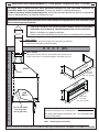
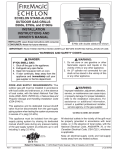
INSTALLATION REQUIREMENTS - FIRE MAGIC SPACER & DUCT COVER
Fire Magic offers a spacer and duct cover specifically designed for your vent hood. Reference the
information below for an overall orientation. (Contact your dealer for ordering information.)
In order to use these prefabricated components, ensure the component dimensions allow for an appropriate
install as addressed below (as individual setups may vary).
Alternatively, a custom spacer and soffit can be constructed that is appropriate for your individual setup.
See the following page for details.
•
•
•
•
THIS VENT HOOD IS FOR OUTDOOR, WALL MOUNT INSTALLATION ONLY.
Installation must be done by a qualified professional service technician.
Below is a diagram of a generic installation.
Please review and understand this section prior to proceeding with installation.
VENT PIPING
Install 10" round galvanized (single wall) vent piping as required.
Installation will depend on roof construction.
R O O F
(8ft)
DUCT COVER
R
Transition
E
(To enclose transition and area above hood. Some installs may not
require a duct cover, as countertop height & roof height may vary. )
A
R
W
A
S
P
A
C
E
R
R
12"
HOOD
C
DU
(bracket)
L
E
OV
TC
20 1/4"
Width varies
by model:
(36", 42", 48", 60")
L
30-33"
R
E
AC
SP
(N
O
N
GAS
GRILL
C
O
18"
M
B
8"
Width varies
by model:
(36", 42", 48", 60")
U
S
T
I
(rear of vent hood
must align with
rear of grill oven)
B
The Spacer depth is based upon 8" between a non-combustible wall
and the rear of the grill (i.e. 4" backsplash + 4" required clearance).
The Duct Cover height is based upon a 33" - 36" countertop height
and an 8' high ceiling.
L
E)
Note:
Drawings are not to scale.
REFER TO INSTALLATION SECTION FOR COMPLETE DETAILS REGARDING ALL INFORMATION FOUND ON THIS PAGE.
REV 2 - 1502191555
9
L-C2-387
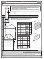
INSTALLATION REQUIREMENTS - CUSTOM SPACER & SOFFIT
When constructing a custom spacer and soffit, reference the information below for an overall orientation.
•
•
•
•
THIS VENT HOOD IS FOR OUTDOOR, WALL MOUNT INSTALLATION ONLY.
Installation must be done by a qualified professional service technician.
Below is a diagram of a generic installation.
Please review and understand this section prior to proceeding with installation.
VENT PIPING
Install 10" round galvanized (single wall) vent piping as required.
Installation will depend on roof construction.
R O O F
SOFFIT *
Transition
R
(To enclose transition and area above hood. Some installs may not
require a soffit, as countertop height & roof height may vary. )
Soffit *
E
A
S
P
A
C
E
R
*†
Custom Soffit Detail *
7.125" (to bracket center line)
HOOD
X
Y
Z
36-VH
distance from
top of vent
hood to roof
B dimension
of spacer
+ 12"
36"
42-VH
distance from
top of vent
hood to roof
B dimension
of spacer
+ 12"
42"
48-VH
distance from
top of vent
hood to roof
B dimension
of spacer
+ 12"
48"
60-VH
distance from
top of vent
hood to roof
B dimension
of spacer
+ 12"
60"
(bracket)
R
30-33"
GAS
GRILL
W
A
L
Model
(rear of vent hood
must align with
rear of grill oven)
L
X
Z
Y
Spacer * †
Custom Spacer Detail * †
Model
A
B
C
36-VH
18"
distance from
rear wall to rear
of grill oven
36"
42-VH
18"
distance from
rear wall to rear
of grill oven
42"
48-VH
18"
distance from
rear wall to rear
of grill oven
48"
60-VH
18"
distance from
rear wall to rear
of grill oven
60"
Note:
A
C
B
Drawings are not to scale.
* Spacer/soffit may be constructed of wood, metal framing, etc. Upon install completion; the exposed sides of the spacer/
soffit may be finished with drywall or other appropriate materials. Dimensions provided here include any finishing substrate.
† The front of the spacer (that is exposed to the rear of the vent hood); must include a solid wall to allow for the vent hood
to be properly secured into it. The soffit must allow permanent interior access (i.e. access panel/door).
REFER TO INSTALLATION SECTION FOR COMPLETE DETAILS REGARDING ALL INFORMATION FOUND ON THIS PAGE.
REV 2 - 1502191555
10
L-C2-387
INSTALLATION
THIS VENT HOOD IS FOR OUTDOOR, WALL MOUNT
INSTALLATION ONLY.
To ensure safety and proper performance; the vent hood
installation must be done by a qualified professional
service technician. Reference the INSTALLATION
REQUIREMENTS section during the course of the install
for dimensions and overall orientation.
Baffle
If possible, the gas grill should be removed for ease of
installation and to prevent damage to the grill.
Fig. 11-1 Remove baffle
Important: Prior to starting installation, the baffle
(inside of vent hood) and the wall mount
bracket (rear of vent hood) must be removed.
Be sure to retain all hardware removed. See
Fig. 11-1 and 11-2.
Wall mount
SPACER
Remove two rows of screws
Fire Magic offers a spacer specifically designed for your
vent hood. Contact your dealer for ordering information.
Alternatively, a custom spacer can be constructed for your
setup. Follow the appropriate section for your spacer type.
Fig. 11-2 Remove wall mount bracket
R O O F
Fire Magic Spacer:
The Fire Magic spacer comes ready to be mounted. It should
be installed 30-33" above the grill, centered, and level.
See Fig. 11-3.
Important: Be sure to allow for the proper clearance above
the spacer for the soffit / duct cover that is to be
installed at a later time.
•
Allow for proper soffit / duct cover
clearance above
•
Spacer must be properly secured
into REAR WALL studs.
•
Spacer has slots & alignment tabs
to aid in leveling / installing
R
E
A
R
S
P
A
C
E
R
1. Locate and mark the REAR WALL studs.
2. Determine the install location of the spacer (30-33" above
the grill). Locate the "left-to-right" center, and pencil a
vertical line on the rear wall. Then pencil a horizontal line
7.5" up from the bottom of the spacer (see Fig. 11-4, A-C).
W
3. Place the spacer over the two lines. Use the alignment
notches found on spacer's center-rear bracket to aid in
proper location and leveling (see Fig. 11-4, D).
L
30 - 33"
A
L
(remove grill
if possible)
Fig. 11-3 Fire Magic spacer orientation
4. Using appropriate mounting hardware for the rear wall
construction; secure the spacer (via the center-rear
bracket) into the rear wall (see Fig. 11-4, E).
mark B
center
F
5. Next use additional mounting hardware, and the support
plates (supplied with spacer), to secure the top-rear of
the spacer into the rear wall (see Fig. 11-4, F).
Important: THE SPACER MUST BE SECURED INTO
MULTIPLE WALL STUDS, USING THE
APPROPRIATE HARDWARE, TO ENSURE
PROPER SUPPORT. METAL FRAMEWORK
WILL REQUIRE ADDITIONAL WALL STUDS
AND SCREWS FOR PROPER SUPPORT.
CONSULT A PROFESSIONAL CONTRACTOR
FOR YOUR INDIVIDUAL SETUP.
E
C
D
align
7.5"
A
30 - 33"
Fig. 11-4 Install Fire Magic spacer (36" shown)
REV 2 - 1502191555
11
L-C2-387
INSTALLATION (cont.)
Custom Spacer:
R O O F
Construct the spacer frame according to your individual
install preference, while following the guidelines found in
the INSTALLATION REQUIREMENTS section. The front of
the spacer (that is exposed to the rear of the vent hood);
must include a solid wall to allow for the vent hood to be
properly secured into it.
R
When designing the spacer; account for the thickness of
your finishing substrate so that overall dimensions are flush
with the vent hood.
R
The spacer should be installed 30-33" above the grill,
centered, and level. See Fig. 12-1.
Important: Be sure to allow for the proper clearance
above the spacer for the soffit / duct cover that
is to be installed at a later time.
1. Locate and mark the REAR WALL studs.
2. Determine the install location of the spacer (30-33"
above the grill).
E
A
S
P
A
C
E
R
•
Allow for proper soffit / duct cover
clearance above
•
Spacer must be properly secured
into REAR WALL studs.
•
Spacer must have a solid front wall
W
30 - 33"
A
L
(remove grill
if possible)
L
Fig. 12-1 Custom spacer orientation
3. Using appropriate mounting hardware for the spacer
and rear wall construction; secure it into the rear wall.
Important: THE SPACER MUST BE SECURED INTO
MULTIPLE WALL STUDS, USING THE
APPROPRIATE HARDWARE, TO ENSURE
PROPER SUPPORT. METAL FRAMEWORK
WILL REQUIRE ADDITIONAL WALL
STUDS AND SCREWS FOR PROPER
SUPPORT. CONSULT A PROFESSIONAL
CONTRACTOR FOR YOUR INDIVIDUAL
SETUP.
4. Install finishing substrate to left and right sides, and
bottom of spacer as appropriate.
A
Apply silicone between
transition and hood
B
Hold transition
in place from
outside
C
Drill 4
screws
from inside
TRANSITION
1. Rest the vent hood on its rear panel.
Fig. 12-2 Install transition
2. Apply a bead of silicone along the bottom of the
mounting flange of the transition before installation
(see Fig. 12-2, A).
3. Position the transition in place and secure using a power
drill with a 1/4" hex driver (or a 1/4" nut driver) and the
(4) supplied #6 x 3/8" hex head screws. Reach into
and fasten the screws from inside the vent hood. (An
additional person should hold the transition in place
while it is being fastened.) See Fig. 12-2, B-C.
REV 2 - 1502191555
12
L-C2-387
INSTALLATION (cont.)
WALL MOUNT BRACKET
The wall mount bracket must be installed into the spacer
to assist in supporting the vent hood.
Fire Magic
Spacer
To install wall mount bracket to Fire Magic Spacer:
Fire Magic spacers are designed with pre-drilled holes and
include screws for ease of bracket installation.
1. Center the bracket (from left-to-right) over the channel
located on the front center of the Fire Magic Spacer.
2. Using a medium Phillips screwdriver and the large 1/420 screws supplied with the spacer, secure the bracket
in place.The spacer has pre-drilled holes. See Fig. 13-1.
To install wall mount bracket to custom spacer:
The bracket should be centered from left to right on the
spacer.The horizontal position of the bracket center must be
7.125" down from the top of the vent hood/spacer. Alignment
notches are provided on the top, bottom, center, and sides
of the bracket to aid in proper location and leveling.
1. Locate the "left-to-right" center of the spacer and pencil
a vertical line. Then pencil a horizontal line 7.125" down
from the top of the spacer (see Fig. 13-2, A-B).
2. Place the bracket over the two lines. Use the alignment
notches in the top, bottom, center, and sides of the
bracket to properly locate and assist in leveling (see
Fig. 13-2, C).
3. Using appropriate mounting hardware for the spacer
construction; secure the bracket onto the spacer (see
Fig. 13-2, D).
Important: THE BRACKET MUST BE SECURED INTO
THE SPACER STUDS TO ENSURE PROPER
SUPPORT. A MINIMUM OF 4 SCREWS WITH
FENDER WASHERS MUST BE EVENLY
DISTRIBUTED AND FASTENED INTO TWO
STUDS. ADDITIONAL SCREWS WILL BE
REQUIRED ACROSS THE BRACKET INTO
THE SPACER WALL, FOR COMPLETE
SUPPORT.
Fig. 13-1 Install wall bracket to F.M. Spacer
align
Custom
Spacer
C
mark A
center
D
7.125"
B
Fig. 13-2 Install wall bracket to custom spacer
To ensure a properly installed bracket, first handtighten all screws. Reposition the bracket as
needed, then fully tighten.
REV 2 - 1502191555
13
L-C2-387
INSTALLATION (cont.)
VENT HOOD
1. Rest the vent hood onto the wall mount bracket, being
sure that the tabs on the bracket engage the slots on
the rear of the hood for proper support. See Fig. 14-1.
2. Ensure the sides, top, and bottom of the vent hood sit
flush with the spacer (see Fig. 14-2). (The spacer will
already be finished with any applicable substrate, to
allow for the vent hood to rest flush.)
3. From the inside of the vent hood; fasten the hood to
the bracket using a medium Phillips screwdriver and
the 1/4-20 screws supplied with the vent hood (that
were originally removed at beginning of installation).
See Fig.14-2, Detail A.
4. From the inside of the vent hood, using appropriate
mounting hardware for the spacer construction; secure
the top portion of the hood directly into the spacer. Use
the supplied support plates when fastening, see Fig.
14-2, Detail B.
Tabs must
engage slots on
rear of hood
Wall mount
bracket
Spacer
Hood
Fig. 14-1 Rest vent hood in place
Fire Magic spacers include these screws (#10 x 3/4").
B
REAR
WALL
Fasten hood
directly into
spacer (support
plates supplied)
(transition not
shown for clarity)
A
Install
supplied
screws
through
hood
into wall
bracket
Spacer
Hood
(Flush)
Countertop
(grill not shown
for clarity)
Fig. 14-2 Secure vent hood (42" shown)
REV 2 - 1502191555
14
L-C2-387
INSTALLATION (cont.)
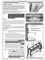
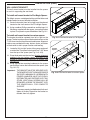
VENT PIPING
Cap
A cutout will need to be made in the roof to route the piping
through; and must be sealed with silicone to prevent leaks.
1. Install 10" round galvanized rigid (single wall) vent
piping from the transition on, as required. All joints
must be sealed using duct tape.
Install 10" round vent piping as needed
(ROOF)
Important: Vent piping should be installed as straight
as possible to prevent back-pressure on the
fans.
Transition
Important: If an offset is required for your installation, a
maximum of two 45˚ elbows may be used.
Do not use 90˚ elbows for this installation.
See Fig. 15-2.
2. Using duct tape and the appropriate hardware; install
a termination cap on top of the vent piping to prevent
water and debris from entering the vent hood.
(vent hood)
Fig. 15-1 Common Installation
INCORRECT
CORRECT
45˚
elbow
Important: A non-restrictive termination cap must be
used. Do not use a restrictive cap for this
installation. See Fig. 15-2.
Installation will depend on roof construction and individual
setup.
90˚
elbow
45˚
elbow
Exceeding a 20 foot total vent piping length will reduce the
effectiveness of your exhaust system.
NEVER use 90˚ elbows
Ok to use a max of two
45˚ elbows
Only use non-restrictive
termination caps
Fig. 15-2 Incorrect/Correct Piping Examples
REV 2 - 1502191555
15
L-C2-387
INSTALLATION (cont.)
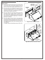
FAN ASSEMBLY
1. Locate the (4) nuts pre-installed to the ceiling of the
vent hood, and using a 3/8" nut driver, loosen (but do
not remove) to allow for the fan assembly to be inserted.
See Fig. 16-1.
B
A
2. With the open ends of the fans facing the front of the
vent hood, carefully position the fan assembly, aligning
the keyholes to the loosened nuts. See Fig. 16-1, A.
3. Mount the fan assembly flush against the vent hood
ceiling ensuring the nuts protrude through the keyholes,
then slide the assembly to the left so that it to hangs
from the nuts. See Fig. 16-1, A and B.
CAUTION: TO PREVENT INJURY OR DAMAGE TO
THE FAN ASSEMBLY, THE FAN MUST
BE SUPPORTED UNTIL IT IS PROPERLY
SECURED IN PLACE.
Fig. 16-1 Insert fan assembly
4. Fasten the (4) nuts to secure the fan assembly in place
(see Fig. 16-2, C).
C
WIRING CONNECTIONS
1. A wire connection exists toward the right rear of the fan
assembly. This is to be connected to the wire harness
coming out the right rear of the vent hood. See Fig.
16-3, D.
Fig. 16-2 Fasten (4) nuts to secure
D
Fig. 16-3 Connect fan assembly wire
REV 2 - 1502191555
16
L-C2-387
INSTALLATION (cont.)
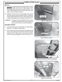
BAFFLE
1. Carefully raise the baffle up into the vent hood. You will
first need to slide one side in at a slight angle, until the
baffle edge aligns above the inner wall (see Fig. 17-1).
Then raise the opposite side of the baffle until it also
aligns. Drop the baffle into place.
2. Align the 4 screw holes (2 on each side), then secure
the baffle in place using a medium Phillips screwdriver
and the supplied 8-32 x 3/8" screws (that were originally
removed at beginning of installation). See Fig. 17-2.
Align baffle to
screw holes
Important: To prevent cross-threading the screws they
should be installed with a manual screwdriver
and a small amount of household grease.
Fig. 17-1 Align baffle
GREASE FILTERS
1. Install the filter spacer (if applicable, 42" models only).
See Fig. 17-3. Repeat for other side.
2. Install a filter into the vent hood by first pressing in the
lever, then aligning the tabs found on the filter into the
notches found in the interior of the hood. The filters
will secure in place. Repeat for all filters. See Fig. 17-4.
Fasten screws
Fig. 17-2 Secure baffle
(Front of
vent hood)
Filter spacer installed
(Baffle)
42" models only
Fig. 17-3 Install filter spacer (if applicable)
Filter
installed
42"
model
shown
Fig. 17-4 Install filters
REV 2 - 1502191555
17
L-C2-387
INSTALLATION (cont.)
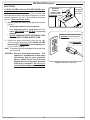
ELECTRICAL
A 120VAC (15 AMP minimum) GFCI GROUNDED 3-wire
receptacle (not included) is required within the vicinity of the
vent hood to provide power to the unit. The area above the
vent hood that the soffit / duct cover will enclose is an ideal
location (reference Fig 18-1). Your individual installation
may vary. Observe all local codes.
1. Wire the receptacle above the top right of the unit (see
Fig 18-1).
• Verify proper polarity of the receptacle.
• If an extension cord is used, ensure it is a
3-wire GROUNDED cord. DO NOT use 2-prong
adapters.
• DO NOT TAMPER WITH THE EXTENSION CORD
OR THE INSERT POWER-SUPPLY CORD.
2. Connect the power cord coming from the top right
of the unit to the previously wired 120VAC (15 AMP
minimum) GFCI GROUNDED 3-wire receptacle (see
Fig. 18-1 and Fig. 18-2).
Receptacle
MUST be:
120VAC (15 AMP
minimum) GFCI
GROUNDED 3-wire
(vent piping
not shown
for clarity)
Fig. 18-1 Install receptacle & connect power cord
120VAC (15 AMP minimum) GFCI
GROUNDED 3-wire receptacle
3-wire GROUNDED
cord from unit
Note: The power cord must be plugged in when operating
the vent hood.
WARNING: Electrical Grounding Instructions - This
appliance is equipped with a three-prong
(grounding) plug for your protection
against shock hazard and should be
plugged directly into a properly grounded
three-prong receptacle. Do not cut or
remove the grounding prong from this plug.
REV 2 - 1502191555
18
Fig. 18-2 Electrical setup detail
L-C2-387
INSTALLATION (cont.)
DUCT COVER / CUSTOM SOFFIT
Note: Some installs may not require a duct cover / soffit, as
island height & roof height may vary.
Fire Magic offers a duct cover specifically designed for your vent
hood. Contact your dealer for ordering information. Alternatively,
a custom soffit can be constructed for your setup. Follow the
appropriate section for your spacer type.
(transition, vent piping, &
electrical not shown for
clarity)
Duct cover
Fire Magic Duct Cover:
The Fire Magic duct cover comes ready to be installed.
(Flush)
1. Carefully slide the duct cover into the area above the
already installed spacer and vent hood. Ensure the bottom
perimeter of the duct cover rests flush with the spacer and
vent hood. See Fig. 19-1.
2. From beneath the vent hood, use a medium Phillips
screwdriver and the 8-32 x 3/8" screws supplied with the
duct cover to secure it to the vent hood. (The screws are
to be fastened through the pilot holes found on top of the
vent hood and into the duct cover above.) See Fig. 19-1
Important: To prevent cross-threading the screws they should
be installed with a manual screwdriver and a small
amount of household grease.
Note: The rear of the duct cover does not need to be secured
to the rear wall.
Important: DO NOT apply sealant to the duct cover as it must
be removable for servicing and for access to the
electrical connection.
Custom Soffit:
Construct the soffit frame according to your individual install
preference, while following the guidelines found in the
INSTALLATION REQUIREMENTS section.
Fig. 19-1 Install Fire Magic Duct Cover
R O O F
R
E
S
O
F
F
I
T
•
Soffit must be properly
secured into REAR WALL
studs.
•
Soffit must have access
panel/door.
A
R
W
A
L
L
(remove grill
if possible)
Fig. 19-2 Custom soffit orientation
When designing the soffit; account for the thickness of your
finishing substrate so that overall dimensions are flush with the
vent hood and spacer below. The soffit must allow permanent
interior access (i.e. access panel/door).
1. Locate and mark the REAR WALL studs.
2. Using appropriate mounting hardware for the soffit and rear
wall construction; secure it into the rear wall. The soffit will
rest directly above the spacer and vent hood.
Important: THE SOFFIT MUST BE SECURED INTO
M U LT I P L E WA L L S T U D S, U S I N G T H E
APPROPRIATE HARDWARE, TO ENSURE
PROPER SUPPORT. METAL FRAMEWORK
WILL REQUIRE ADDITIONAL WALL STUDS
AND SCREWS FOR PROPER SUPPORT.
CONSULT A PROFESSIONAL CONTRACTOR
FOR YOUR INDIVIDUAL SETUP.
3. Install finishing substrate to left and right sides, and front
of soffit as appropriate.
Important: The soffit must allow permanent interior access
(i.e. access panel/door).
REV 2 - 1502191555
19
L-C2-387
OPÉRATION
VENTILATEUR DE CAPOT DE PASSAGE
Pour faire fonctionner les ventilateurs, il suffit de tourner
le bouton du ventilateur situé à l'avant droit de la hotte au
réglage désiré. Le bouton du ventilateur est symbolisé par
un logo fan gravé à côté de lui. Voir la Fig. 20-1.
VENTILATEUR
LUMIÈRES
Tournez le bouton à la position OFF pour allumer les
ventilateurs éteints.
Mettez toujours les fans avant de cuisson afin d'établir un
flux d'air. Permettre aux ventilateurs de fonctionner pendant
quelques minutes après que vous allumez le gril off, pour
assainir l'air et d'en garder la zone sans fumée.
Note: La hotte d'aspiration est équipé d'un interrupteur
thermique interne. Lorsque la zone environnante
atteint la température, l'interrupteur thermique
se met automatiquement sur les ventilateurs de
la hotte de ventilation. Lorsque la hotte est en
fonctionnement sur le réglage LO, il passera
automatiquement au réglage de HI pour maintenir
une température de fonctionnement. Cette fonction
est une commodité et évite d'endommager la hotte.
Fig. 20-1 Control Panel Detail
ÉCLAIRAGE SUPÉRIEUR DE GRIL
Les lampes halogènes sont contrôlés en tournant le bouton
de lumière situé sur le côté avant droit de la hotte au
réglage désiré. Le bouton lumière est symbolisée par un
logo d'ampoule gravé à côté de lui. Voir Fig. 20-1.
Tournez le bouton à la position OFF pour éteindre les
lumières.
Nettoyer la hotte sur une base régulière pour assurer
une performance optimale. Voir la section ENTRETIEN
ET NETTOYAGE pour plus de détails.
REV 2 - 1502191555
20
L-C2-387
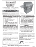
OPERATION
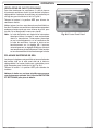
VENT HOOD FANS
To operate the fans, simply turn the fan knob located on
the front right of the vent hood to your desired setting. The
fan knob is symbolized with a fan logo etched beside it.
See Fig. 21-1.
FANS
LIGHTS
Turn the knob to OFF position to turn the fans off.
Always turn the fans on before cooking to establish an air
flow. Allow the fans to operate for few minutes after you turn
the grill off, to clear the air out and keep the area smoke free.
Note: The vent hood is equipped with an internal thermal
switch. When the surrounding area reaches
temperature, the thermal switch will automatically
turn on the vent hood fans. When the vent hood is
operating on the LO setting, it will automatically
switch to the HI setting to maintain a safe operating
temperature. This feature is for convenience and
prevents damage to the vent hood.
Fig. 21-1 Control knobs
GRILL TOP LIGHTING
The halogen lights are controlled by turning the light knob
located on the front right side of the vent hood to your desired
setting. The light knob is symbolized with a light bulb logo
etched beside it. See Fig. 21-1.
Turn the knob to OFF position to turn the lights off.
Clean the vent hood on a regular basis to ensure optimal
performance. See the SERVICING AND CLEANING
section for details.
REV 2 - 1502191555
21
L-C2-387
SERVICING AND CLEANING
The unit must be off and the power cord must be
disconnected prior to beginning any service or cleaning.
Any components removed during servicing/cleaning
must be reinstalled, as previously instructed in this
manual, prior to future operation. CONTACT YOUR
DEALER FOR REPLACEMENT PARTS.
Wipe with grain
REMOVE FIRE MAGIC DUCT COVER (if applicable)
If a Fire Magic Duct Cover is installed, it must first be
removed in order to access and disconnect the power cord.
To remove, use a medium Phillips screwdriver to unfasten
the screws found along the interior top perimeter of the
vent hood. Store the screws for later re-installation (after
service is complete).
Fig. 22-1 Clean vent hood
STAINLESS STEEL CARE
Clean your vent hood by first using Fire Magic Barbecue
and Grill Cleaner (part #3580-1) to remove grease and
dirt. Always wipe with the grain (See Fig. 22-1). Next, use
Fire Magic Stainless Steel Cleaner (3581-1) to restore
the stainless steel color. Finish by wiping your vent hood
down using Fire Magic Polish Wipes (3586-1).
Press in
lever and
remove
Clean your vent hood at least once a month.
If your vent hood is installed in a seaside (salt air) or pool side
(chlorine) location, it will be more susceptible to corrosion
and must be maintained/cleaned more frequently. Do not
store chemicals (such as chlorine or fertilizer) near your
stainless steel appliance.
Fig. 22-2 Clean grease filters
Due to the nature of stainless steel, surface iron oxide
deposits may appear. Do not be alarmed – these deposits
are removable with stainless-steel cleaner through prompt
and periodic maintenance. If not attended to promptly,
permanent pitting may occur.
GREASE FILTERS
Wash the filters frequently either in a detergent solution, or
by placing them in your dishwasher. Cleaning the filters on
a regular basis (depending on usage) will ensure optimal
performance and longevity of the vent hood.
To remove a filter; simply press in the lever and pull it away
from the vent hood (see Fig. 22-2).
Once the filters are clean, reinstall each into the vent hood
by first pressing in the lever, then aligning the tabs found on
the filter into the notches found in the interior of the hood.
The filters will secure in place.
Important: If a filter becomes damaged or not cleanable;
it must be replaced.
FANS
Clean the fans on a regular basis (depending on usage) with
a damp towel to ensure optimal performance. (The grease
filters and baffle will need to be removed to gain access.)
REV 2 - 1502191555
22
L-C2-387
SERVICING AND CLEANING (cont.)
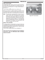
REPLACING HALOGEN BULBS
Important: ONLY REPLACE WITH 120V / 50 WATT
HALOGEN BULB(S).
Important: Wear gloves during this procedure for safety
and to maintain bulb life.
1. Ensure the power cord has been disconnected.
2. With one hand directly below the light assembly, gently
pry the glass lens out using a thin flat-head screwdriver.
Slowly twist the screwdriver handle until the lens is
removed.
Note: Replacement should only be done on a light
assembly that is completely cool.
Glass lens
Fig. 23-1 Light orientation
3. Clean the lens with a standard household window
cleaner, dry completely, and set aside.
4. Gently remove the bulb from its socket.
5. Install a new 120V / 50 watt halogen bulb into the
socket, being sure that both pins are properly inserted.
Bulb
Important: Bulb is halogen. DO NOT TOUCH with bare
hands. Oils from hands drastically reduce
bulb life.
6. Place the lens back into the fixture and snap it into place.
Note: The curved cutout of the lens should align over the
bulb when replacing the lens.
Socket
Fig. 23-2 Replace bulb
7. Repeat as needed.
8. Reconnect the power cord and test.
REV 2 - 1502191555
23
L-C2-387
NOTES PAGE
Please use this page to record any information that you may want to have at hand.
REV 2 - 1502191555
24
L-C2-387
TROUBLESHOOTING
If you have trouble with this vent hood, please use this list to identify the problem. By trying one or more of the
solutions to the possible cause, you should be able to solve the problem. If this list does not cover your present
problem, or if you have other technical difficulties with the vent hood, please contact your local Fire Magic dealer
or visit our web site at www.rhpeterson.com.
PROBLEM
Unit does not
turn on
Loss of suction
Switch
malfunction
Fan malfunction
Lights do not
turn on
REV 2 - 1502191555
POSSIBLE CAUSE
CORRECTION
1a. Check if unit is plugged in.
1. No power to hood
2. Switch malfunction
1b. Check if GFCI receptacle is tripped.
2.
Check or replace switch.
1. Grease filter(s) clogged
1. Clean or replace filter(s).
2. Fan(s) not operating
2. Check or replace fan(s).
3. Fan(s) obstructed
3. Check fan(s) for possible obstructions.
1. Defective switch
1. Check or replace switch.
2. Wire harness shorted/disconnected
2. Check wire harness connection.
1. Defective fan
1. Check or replace fan.
2. Wire harness shorted/disconnected
2. Check wire harness connection.
3. Fan(s) obstructed
3. Check fan(s) for possible obstructions.
4. Defective switch
4. Check or replace switch.
1. Bulb burned out
1. Replace bulb.
2. Defective switch
2. Check or replace switch.
25
L-C2-387
WARRANTY
PETERSON FIRE MAGIC GRILLS AND ACCESSORIES
LIMITED WARRANTY
Robert H. Peterson Co. ("RHP") warrants your Fire Magic® grill to be free from defects in material and workmanship.
Fire Magic® cast stainless-steel burners, stainless-steel rod cooking grids, and stainless-steel housings are warranted for as long as you own
your Fire Magic® grill -- LIFETIME. (Except as noted below.)
Fire Magic Choice stainless steel tubular burners are warranted for TWENTY (20) YEARS.
Fire Magic® cast brass burners, brass valves, inner liners, manifold assemblies, and backburner assemblies (except ignition parts) are
warranted for FIFTEEN (15) YEARS.
Fire Magic® Electric Grills, including stainless steel grid, and housings are warranted for TEN (10) YEARS.
Fire Magic® Infra-red burners, flavor grids, Charcoal stainless steel grills, and Smokers are warranted for FIVE (5) YEARS; except for the
charcoal pan, charcoal grid, wood pellet screen, thermometer, and ash tray; which are warranted for ONE (1) YEAR.
Fire Magic® sideburners and all other Fire Magic® grill components (except ignition and electronic parts) are warranted for THREE (3)
YEARS.
Fire Magic® ignition systems (excluding batteries), electronic components (including lights and thermometers), and grill accessories are
warranted for ONE (1) YEAR.
A COPY OF YOUR SALES SLIP FOR PROOF OF PURCHASE IS REQUIRED
This warranty applies to the original purchaser for products which are installed in the United States or Canada and which are operated and maintained
as intended for single family residential usage. This warranty is valid only with proof of purchase, shall commence on the date of purchase, and shall
terminate (both as to original and any replacement products) on the anniversary date of the original purchase of the product stated on the above schedules.
This warranty covers defects in material and workmanship. This warranty does not cover parts which become defective as a result of negligence, misuse,
use not in compliance with the Owner’s Manual/Installation Instructions, accidental damage, improper handling, improper storage, improper installation,
lack of required routine maintenance (as specified in the Owner’s Manual/Installation Instructions), electrical damage, local gas impurities or failure to
protect against combustibles. Product must be installed (and gas must be connected) as specified in the Owner’s Manual/Installation Instructions by
a qualified professional installer. Modifications to products which are not specifically authorized will void this warranty. Accessories, parts, valves,
remotes, etc. when used must be Peterson products or this warranty is void. Warrantied items will be repaired or replaced at Peterson’s sole discretion.
This warranty does not apply to rust, corrosion, oxidation, or discoloration unless the affected part becomes inoperable.
This warranty does not cover labor or labor related charges, except as provided by separate specific written programs from the Peterson Co. All repair
work must be performed by a qualified professional service person and requires prior approval of Peterson.
Peterson may require the defective product or part to be returned to the factory to determine the cause of failure. Peterson will pay freight charges if
the product or part is determined to be defective. This warranty does not cover breakage in shipment from our (Independent) distributor to its customer
if the damage is determined to have occurred during that shipment.
This warranty specifically excludes liability for indirect, incidental, or consequential damages. Some states and provinces do not allow the exclusion
or limitation of incidental or consequential damages, so the above exclusion may not apply to you. This warranty gives you specified legal rights, and
you may have other rights that vary from state to state or province.
For additional information regarding this warranty, or to place a warranty claim, contact the R. H. Peterson dealer where the product was purchased.
TO REGISTER YOUR PRODUCT ONLINE GO TO: WWW.RHPETERSON.COM,
AND CLICK ON PRODUCT REGISTRATION. THANK YOU FOR YOUR PURCHASE.
Quality Check
Date:_________________
Electrical Leak Test:
_____________________
Model#:
___________________
Operational Test:
_____________________
Serial#:
___________________
Inspector:
_____________________
Robert H. Peterson Co. • 14724 East Proctor Avenue • City of Industry, CA 91746
26