1
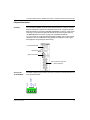
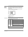
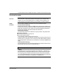
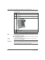
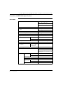
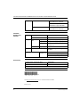
ConneXium
Ethernet Switch
499NES18100
8-Port, 10/100 Base-TX
Quick Reference Guide
31005416 02
Version 2.0
ConneXium Ethernet Switch 499NES18100 8-Port 10/100 Base-TX Quick Reference Guide
Important Information
NOTICE
Read these instructions carefully, and look at the equipment to become familiar with
the device before trying to install, operate, or maintain it. The following special
messages may appear throughout this documentation or on the equipment to warn
of potential hazards or to call attention to information that clarifies or simplifies a
procedure.
The addition of this symbol to a Danger or Warning safety label indicates
that an electrical hazard exists, which will result in personal injury if the
instructions are not followed.
This is the safety alert symbol. It is used to alert you to potential personal
injury hazards. Obey all safety messages that follow this symbol to avoid
possible injury or death.
DANGER
DANGER indicates an imminently hazardous situation, which, if not avoided, will
result in death, serious injury, or equipment damage.
WARNING
WARNING indicates a potentially hazardous situation, which, if not avoided, can result
in death, serious injury, or equipment damage.
CAUTION
CAUTION indicates a potentially hazardous situation, which, if not avoided, can result
in injury or equipment damage.
PLEASE NOTE
2
Electrical equipment should be serviced only by qualified personnel. No responsibility is assumed by Schneider Electric for any consequences arising out of the use
of this material. This document is not intended as an instruction manual for untrained
persons.
© 2004 Schneider Electric. All Rights Reserved.
31005416 02 August 2004
ConneXium Ethernet Switch 499NES18100 8-Port 10/100 Base-TX Quick Reference Guide
Physical Description
Summary
The ConneXium 499NES18100 rail switch supports Ethernet 10 base-T and Fast
Ethernet 100 base-TX operations in industrial environments. It supports switched
Ethernet networks in accordance with IEEE standard 802.3 or 802.3u, using copper
technology. The module has eight RJ45 twisted-pair ports that support eight 10/
100 MBit/s Ethernet connections. It plugs onto a standard ISO/DIN rail.
You can connect up to eight data terminal equipment (DTE) units or other network
segments to the 10/100 Mbit/sports using twisted-pair cabling.The ports support
autonegotiation, autopolarity and autocrossing.
five-pin terminal block
LED display
eight-pin DIP-switch
eight 10/100-base-T(X) ports
(RJ45 connectors)
The supply voltage and the indicator contact are connected to the switch module via
a five-pin terminal block:
31005416 02 August 2004
+24 V
+24 V
Fault
The Five-pin
Terminal Block
3
ConneXium Ethernet Switch 499NES18100 8-Port 10/100 Base-TX Quick Reference Guide
Voltage supply
WARNING
POWER SUPPLY GUIDELINES
The device is designed for safety extra-low voltage (SELV) operation. It may be
connected only to the supply voltage shown on the type plate.
When the module is operated with an external power supply, use only a SELV
supply that complies with IEC 950/EN 60 950/VDE 0805.
Connect the protecting line before you establish any further connections. When
you remove connections, disconnect the protecting line last.
Relevant for North America: The subject unit is to be supplied by a Class 2 power
source complying with the requirements of the National Electrical Code, table
11(b). If power is supplied redundantly (with two individual power sources), the
power sources together should comply with the requirements of the National
Electrical Code, table 11(b).
Relevant for North America: Use 60/75° C copper (CU) wire only.
Failure to follow this precaution can result in death, serious injury, or
equipment damage.
Redundant voltage supplies are supported. Both inputs are decoupled. There is no
load distribution. With redundant supplies, the power pack supplies only the switch
module with the higher output voltage. The supply voltage is electrically isolated
from the housing.
Indicator contact
The indicator contact is used to supervise the functions of the ConneXium
499NES18100 switch, facilitating remote diagnosis without management software.
A contact interrupt uses a potential-free indicator contact (a closed circuit relay
contact) that indicates:
z the failure of at least one of the two supply voltages
z a permanent fault in the switch (internal 3.3 VDC voltage, supply voltage 1 or 2
less than 9.6 V)
z faulty link status on at least one port. The indication of the link state on the
499NES18100 switch can be masked on a port-by-port basis using DIP switches
LA1 ... LA8
The switch module is shipped with no link test.
Note: In the case of the voltage supply being routed without redundancy, the ConneXium
499NES18100 indicates the failure of a supply voltage. You can prevent this message by
feeding in the supply voltage through both inputs.
4
31005416 02 August 2004
ConneXium Ethernet Switch 499NES18100 8-Port 10/100 Base-TX Quick Reference Guide
The 10/100
Base-T(X)
Connections
Eight 10/100 Mbit ports (eight-pin R45 sockets) on the ConneXium 499NES18100
allow eight DTE or other independent network segments complying with the
standards IEEE 802.3 100BASE-TX / 10BASE-T to be connected. These ports
support autopolarity.
The socket casings are electrically connected to the front panel of the switch
module.The pin configuration complies with MDI-X:
pin 8
pin 7
pin 6
pin 5
pin 4
pin 3
pin 2
pin 1
pins 3 and 6 provide one line pair
pins 1 and 2 provide another line pair
remaining pins are not used
The LED Display
The ConneXium 499NES18100 switch module provides 11 display elements that
indicate power status, fault detection and port status:
Indicator
Color
Meaning
P1
green
on when power supply voltage 1 is present
off when power supply voltage 1 is below 9.6 V
P2
green
on when power supply voltage 2 is present
off when power supply voltage 2 is below 9.6 V
FAULT
red
on when an error is present
off when no errors have been detected
DA/STAT
1 ... 8
green or
yellow
off either when no valid link is on the port or when the DA/STAT
message for that port has been suppressed.*
steady green when the link is valid and data is not being received
flashes yellow while data is being received
* Link status indications can be suppressed using the eight-pin DIP switch on the module’s
front panel.
31005416 02 August 2004
5
ConneXium Ethernet Switch 499NES18100 8-Port 10/100 Base-TX Quick Reference Guide
The Eight-pin DIP
Switch
Using the eight-pin DIP switch on the front panel, you can suppress the messages
about the link status of any or all port connections:
0
1
LA1
LA2
LA3
LA4
LA5
LA6
LA7
LA8
LA1 If the switch is set to 0, the message to the DA/STAT 1 LED is suppressed.
LA2 If the switch is set to 0, the message to the DA/STAT 2 LED is suppressed.
LA3 If the switch is set to 0, the message to the DA/STAT 3 LED is suppressed.
LA4 If the switch is set to 0, the message to the DA/STAT 4 LED is suppressed.
LA5 If the switch is set to 0, the message to the DA/STAT 5 LED is suppressed.
LA6 If the switch is set to 0, the message to the DA/STAT 6 LED is suppressed.
LA7 If the switch is set to 0, the message to the DA/STAT 7 LED is suppressed.
LA8 If the switch is set to 0, the message to the DA/STAT 8 LED is suppressed.
Ground
Connection
6
The switch is grounded via the separated ground screw. It is located on the left
under the front panel.
Make sure that the electrical installation meets local or nationally applicable safety
regulations.
31005416 02 August 2004
ConneXium Ethernet Switch 499NES18100 8-Port 10/100 Base-TX Quick Reference Guide
Functional Description
Overview
The 10/100 base-T ports provide terminal connections for the connected LAN
segment. You can connect single devices or complete network segments. The
module supports several frame switching, TP/TX interface, and other functions.
Switch
Functions
The ConneXium 499NES18100 supports four frame switching functions:
Store and forward switching:
All data received by the ConneXium 499NES18100 switch from the system bus or
at the ports are stored and checked for validity. Invalid and defective frames (frames
greater than 1536 bytes or with a CRC error) and frame fragments (greater than
64 bytes) are discarded. The switch forwards the valid frames.
Multi-address switching:
The switch learns all its source addresses on a per-port basis. Only packets with
z unknown addresses
z addresses learned at the specific port
z a multi-broadcast address
in the destination address field are sent to the port.
A switch can learn up to 1000 addresses. This becomes necessary if more than one
terminal device is connected to one or more port(s). Multi-address switching allows
several independent subnetworks to be connected to a ConneXium 499NES18100
switch.
Learned address switching?
The switch monitors the age of the learned addresses and deletes entries from the
address table when they exceed a certain age (300 s).
Note: Restarting deletes the learned address entries.
Tagging
The switch includes a VLAN tag (designated by the IEEE 802.1 Q standard) in a
MAC data frame for VLAN and prioritizing functions. The tag comprises four bytes—
a two-byte tag protocol identifier (TPID) and two bytes of tag control information
(TCI). It is inserted between the source address field and the type field. Data packets
with VLAN tags are transmitted unchanged by the 499NES18100.
31005416 02 August 2004
7
ConneXium Ethernet Switch 499NES18100 8-Port 10/100 Base-TX Quick Reference Guide
TP/TX Interface
The TP/TX interface supports three specific functions:
Link control
The switch monitors the connected TP/TX line segments for short circuits and
interrupts. It uses regular link test pulses in accordance with IEEE standard 802.3
for 10/100 base-T. The switch module does not transmit any data to a TP/TX
segment from which it does not receive a link test pulse.
Note: An unpopulated connection is assessed as a line interrupt. The TP/TX line
to any terminal equipment that has been switched off is also assessed as a line
interrupt since a de-energized bus coupler cannot transmit link test pulses.
Autopolarity exchange
The switch automatically reverses polarity if the receive line pair is incorrectly
connected—if RD+ and RD- are switched.
Autocrossing
The switch detects the transmit and receive pairs (MDI, MDI-X). It automatically
configures its port for the correct transmit and receive pins. Consequently, it does
not matter whether you connect devices using a cross-over or straight cable.
Additional
Features
If the input voltages fall below a threshold, the ConneXium 499NES18100 switch will
be reset. After a reset, the ConneXium 499NES18100 switch will initialize.
ConneXium 499NES18100 Assembly and Startup
Unpacking
When you unpack the ConneXium 499NES18100 switch module, compare your
package content with the scope of delivery provided in the product
specifications.Make sure that the delivery is complete and that none of the parts are
damaged. Use only undamaged parts when you assemble the module.
Assembly
DANGER
ELECTRIC SHOCK HAZARD
Never insert pointed objects (thin screwdrivers, wires, etc.) into the inside of the subrack,
especially in the area behind the socket connectors.
Failure to follow this precaution will result in death, serious injury, or equipment
damage.
8
31005416 02 August 2004
ConneXium Ethernet Switch 499NES18100 8-Port 10/100 Base-TX Quick Reference Guide
WARNING
EXPOSED ELECTRICAL COMPONENTS
Switch the basic devices on only when the case is closed.
Failure to follow this precaution can result in death, serious injury, or equipment
damage.
WARNING
HOUSING SAFETY GUIDELINES
The ventilation slits must not be covered, inhibiting free air circulation. The distance to the
ventilation slots of the housing has to be a minimum of 10 cm.
Failure to follow this precaution can result in death, serious injury, or equipment
damage.
WARNING
RADIO INTERFERENCE
This is a Class A device. This equipment may cause radio interference if it is used in a
residential area. It is the operator´s responsibility to take appropriate preventative
measures.
Failure to follow this precaution can result in death, serious injury, or equipment
damage.
31005416 02 August 2004
9
ConneXium Ethernet Switch 499NES18100 8-Port 10/100 Base-TX Quick Reference Guide
The equipment is delivered in a ready-to-operate condition. Follow this procedure to
assemble the switch.
Notes
Step
Action
1
Check whether the DIP switch pre-settings suit your application (See The Eight-pin
DIP Switch, p. 6).
2
Pull the five-pin terminal block off the switch module and wire up the supply voltage
and indicator lines.
3
Fit the 499NES18100 on a 35 mm standard DIN EN 50 022 rail.
4
Attach the upper snap-on slide bar on the module to the DIN rail and press it down
until it locks in position.
5
Fit the signal lines.
z The front panel of the ConneXium 499NES18100 switch module is grounded via
a separate ground connection.
z Do not open the module housing.
z The shielding ground of the twisted-pair lines that can be connected is electrically
Startup
Dismantling
10
connected to the front panel.
To start up the ConneXium 499NES18100 switch module, connect the supply
voltage via the five-pin terminal block.
To take the ConneXium 499NES18100 switch module off the ISO/DIN rail, insert a
screwdriver horizontally under the housing into the locking slide, pull it downward
(without tipping the screwdriver), and lift the module upward.
31005416 02 August 2004
ConneXium Ethernet Switch 499NES18100 8-Port 10/100 Base-TX Quick Reference Guide
ConneXium 499NES18100 Specifications
General Data
Operating voltage
NEC Class 2 SELV/PELV 24 VDC
(-25% +33%) power source
redundant inputs decoupled
5 A maximum
Buffer time
10 ms @ 24 VDC minimum
Potential difference between input voltage and
housing
32 VDC @ +24 VDC
Current consumption@ 24 VDC
7.0 W maximum
Overload current protection at input
non-changeable fuse
Dimensions (W x H x D)
47 x 135 x 111 mm (1.9 x 5.3 x 4.4 in)
Weight
-32 VDC @ ground
230 g (.507 lb)
Temperature
ambient
storage
Humidity)
0 ... 60º C (32 ... 140º F)
- 20 ... +80º C (-4 ... +176º F
up to 95% (noncondensing
Atmospheric pressure
maximum length of a twistedpair segment
79 kPa minimum
connected to a 10
base-T/100 baseTX TP/TX port
100 m (328 ft)
Protection type
IP 20
Radiated emission
CFR-47 Part 15 Class A,
Germanischer Lloyd Guidelines for the
Performance of Type Tests Part 1 EN
55022 Class A
Interference
proof
static discharge contact
air
EN 61000-4-2 Test level 3
electromagnetic fields
EN 61000-4-3 Test level 3
fast transients
EN 61000-4-4 Test level 3
surge voltage
symmetrical
asymmetrical
cable-based RF faults
31005416 02 August 2004
EN 61000-4-2 Test level 3
EN 61000-4-5 Test level 2
EN 61000-4-5 Test level 3
EN 61000-4-6 Test level 3
11
ConneXium Ethernet Switch 499NES18100 8-Port 10/100 Base-TX Quick Reference Guide
Stability
vibration
IEC 60068-2-6 Test FC, testing level in
line with IEC 61131-2 E2 CDV
Germanischer Lloyd Guidelines for the
Performance of Type Tests Part 1
shock
Interfaces,
Displays and
Controls
Interfaces
Displays
IEC 60068-2-27 Test Ea, testing level in
line with IEC 61131-2 E2 CDV
eight TP/TX ports
RJ45 sockets, 10/100 MBit/s
indicator contact
1 A maximum, 24 V
equipment status 1 green
LEDs
1 green
P1 – power 1, supply voltage 1 present
1 red
Controls
P2 – power 2, supply voltage 2 present
FAULT – indicator contact is open and
indicates error
port status LEDs 8 green/yellow
DAT/STAT 1 ... 8 – data/link status
eight-pole DIP switch
LA1 ... LA8 – suppress messages about
link status
Scope of delivery
order number:
499NES18100
ConneXium rail switch module
terminal block for supply voltage
installation and operating instructions
Accessories
TF Ethernet SFTP CAT5 RJ45 cables
490NTW000**
TF Ethernet SFTP CAT5 RJ45 crossed cables
490NTC000**
where ** = length in meters; allowable choices are 2, 5, 12, 40 or 80.
02
Visit http://www.schneider-electric.com for your nearest Schneider Electric affiliate.
Printed in France
12
31005416 02 August 2004