1
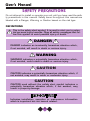
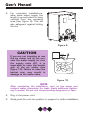
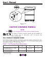
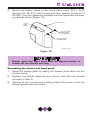
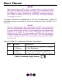
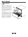
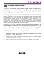
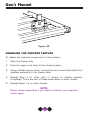
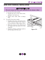
INTRODUCTION
Congratulations on your purchase of your U-Line drawer unit. A pioneer in
the field for more than 40 years, U-Line is the world’s number one manufacturer of built-in, under-counter ice making and specialty refrigeration
products. U-Line dedicates 100% of its research and development to
these products. The result: U-Line technology leads the market with innovation, design, depth of product line and performance.
U-Line also backs customers with a strong dealer network.
U-Line’s commitment to quality even extends to environmentally safe
packaging. U-Line products are making life more convenient in homes,
businesses, and hotels around the world.
PLEASE READ all instructions completely before attempting
to install or operate the unit.
The icons
2075DWRR refrigerator unit,
CO2075DWR
refrigerator/ice maker combination and
2075DWRWC Wine
Captain® drawer units are used throughout this manual to help you identify the
specifics to your U-Line product. Once you have your unit installed, we suggest
you keep this manual in a safe place for future reference. Should any problems occur, refer to the TROUBLESHOOTING section of this manual. This
information will help you quickly identify a problem and get it remedied. In the
event you require assistance, please contact the dealer where you purchased
your unit.
1
User’s Manual
PLEASE RECORD YOUR MODEL’S INFORMATION
Whenever you call to request information or service, you will need to
know your model number and serial number. You can find this information on the serial plate located on the inside wall of your unit and on the
product registration card.
PRODUCT REGISTRATION CARD
The package containing this manual also includes your product registration information. Warranty coverage begins at the time your unit was
purchased.
NOTE
Complete and mail the Product Registration Card as soon as
possible to validate the registration date. You may also register the product online at www.U-LineService.com.
If you do not return your Product Registration Card, U-Line will use the
date of sale to the U-Line distributor as the first date of
warranty for your unit. Please also record the purchase date of your ULine unit and your dealer’s name, address and telephone number.
Model Number:
______________________________________
Serial Number:
______________________________________
Purchase Date:
______________________________________
Dealer Name:
______________________________________
Dealer Address:
______________________________________
Dealer Telephone: ______________________________________
Keep this manual and the sales receipt together in a safe place for further
reference.
2
TABLE OF CONTENTS
INTRODUCTION . . . . . . . . . . . . . . . . .
SAFETY PRECAUTIONS . . . . . . . . . . . .
INSTALLATION . . . . . . . . . . . . . . . . .
LEVELING THE UNIT . . . . . . . . . . . . . .
CONNECTING THE WATER SUPPLY . . . .
BUILT-IN INSTALLATION . . . . . . . . . . .
CUSTOM DRAWER PANELS . . . . . . . .
INITIAL START-UP AND ADJUSTING THE
TEMPERATURE CONTROL . . . . . . . . . .
.
.
.
.
.
.
.
.
.
.
.
.
.
.
.
.
.
.
.
.
.
.
.
.
.
.
.
.
.
.
.
.
.
.
.
.
.
.
.
.
.
.
.
.
.
.
.
.
.
.
.
.
.
.
.
.
.
.
.
.
.
.
.
.
.
.
.
.
.
.
.
.
.
.
.
.
.
.
.
.
.
.
.
.
.
.
.
.
.
.
.
.
.
.
.
.
.
.
.
.
.
.
.
.
.
.
.
.
.
.
.
.
.
.
.
.
.
.
.
. .1
. .4
. .6
. .9
.11
.13
.14
. . . . . . . . . . . . . . . . . .22
TEMPERATURE CONTROLLER . . . . . . . . . . . . . . . . . . . . .23
TEMPERATURE CONTROLLER . . . . . . . . . . . . . . . . . . . . .24
TEMPERATURE CONTROLLER . . . . . . . . . . . . . . . . . . . . .26
OPERATION . . . . . . . . . . . .
ICE MAKER . . . . . . . . . . . .
CLEANING & MAINTENANCE .
STAINLESS STEEL MODELS
STORAGE . . . . . . . . . . . . . .
TROUBLESHOOTING . . . . . . .
.
.
.
.
.
.
.
.
.
.
.
.
.
.
.
.
.
.
.
.
.
.
.
.
.
.
.
.
.
.
.
.
.
.
.
.
.
.
.
.
.
.
.
.
.
.
.
.
.
.
.
.
.
.
.
.
.
.
.
.
.
.
.
.
.
.
.
.
.
.
.
.
.
.
.
.
.
.
.
.
.
.
.
.
.
.
.
.
.
.
.
.
.
.
.
.
.
.
.
.
.
.
.
.
.
.
.
.
.
.
.
.
.
.
.
.
.
.
.
.
.
.
.
.
.
.
.
.
.
.
.
.
.
.
.
.
.
.
.
.
.
.
.
.
.30
.36
.38
.38
.41
.42
TROUBLESHOOTING . . . . . . . . . . . . . . . . . . . . . . . . . . .43
TROUBLESHOOTING . . . . . . . . . . . . . . . . . . . . . . . . . . .44
TROUBLESHOOTING . . . . . . . . . . . . . . . . . . . . . . . . . . .45
IF SERVICE IS REQUIRED . . . . . . . . . . . . . . . . . . . . . . . . . . . . .46
REPLACEMENT PARTS . . . . . . . . . . . . . . . . . . . . . . . . . . . . . .46
3
User’s Manual
SAFETY PRECAUTIONS
Do not attempt to install or operate your unit until you have read the safety precautions in this manual. Safety items throughout this manual are
labeled with a Danger, Warning or Caution based on the risk type.
DEFINITIONS
!
This is the safety alert symbol. It is used to alert you to potential personal injury hazards. Obey all safety messages that follow this symbol to avoid possible injury or death.
! DANGER !
DANGER indicates an imminently hazardous situation which,
if not avoided, will result in death or serious injury.
! WARNING
WARNING indicates a potentially hazardous situation which,
if not avoided, could result in death or serious injury.
! CAUTION
CAUTION indicates a potentially hazardous situation which, if
not avoided, may result in minor or moderate injury.
CAUTION
CAUTION used without the safety alert symbol indicates a
potentially hazardous situation which, if not avoided, may
result in property damage.
Indicates installation, operation or mainenance information
which is important but not hazard related.
4
GENERAL PRECAUTIONS
! DANGER !
RISK OF CHILD ENTRAPMENT. Before you throw away your
old refrigerator or freezer, take off the doors and leave
shelves in place so that children may not easily climb inside.
! WARNING
• Never attempt to repair or perform maintenance on the
unit until the electricity has been disconnected.
• Altering, cutting of power cord, removal of power cord,
removal of power plug, or direct wiring can cause serious
injury, fire and/or loss of property and/or life and will void
the warranty.
• The anti-tip kit must be installed on this unit before it is
used. Never use the drawers as steps or a shelf to support more than the drawers’ content.
CAUTION
• Do not lift unit by drawer’s handle.
• Use care when moving the unit. Some edges are sharp and
may cause personal injury. Wear gloves when moving or
repositioning the unit.
• Allow unit temperature to stabilize for 24 hours before use.
• Failure to clean the condenser every three months can
cause the unit to malfunction. This could void the warranty.
• Never install the unit behind closed doors. Be sure front
grille is free of obstruction. Obstructing free air flow can
cause the unit to malfunction, and may void the warranty.
CAUTION
• Use only genuine U-Line replacement parts. Imitation parts
can damage the unit, and may void the warranty.
5
User’s Manual
INSTALLATION
SITE PREPARATION
Your U-Line drawer unit must be installed under a counter or in a wall.
These units are designed so they can be installed next to a wall. The
crisper in the
either side.
and the caddy in the
can be accessed from
1.
Position the unit on a flat, level surface, capable of supporting the
entire weight of the unit. Remember the unit will be significantly
heavier once it is fully loaded.
2.
This unit requires grounded and polarized 115 VAC, 60Hz, 15A circuit (normal household current).
! DANGER !
ELECTROCUTION HAZARD!
Electrical Grounding Required. This appliance
is equipped with a three prong (grounding)
polarized plug for your protection against possible shock hazards.
• NEVER remove the round grounding prong from the plug.
• NEVER use a two-prong grounding adapter.
• NEVER use an extension cord to connect power to the
unit.
Where a two-prong wall receptacle is encountered or a
longer power cord is required, contact a qualified electrician
to have it replaced in accordance with applicable electrical
codes.
6
Your U-Line Drawer unit is designed so it can be installed next to the wall
on either side (Figures 1, 2).
DWR001A
Figure 1 – Right wall installation
! WARNING
The anti-tip kit must be installed on this unit before it is used.
Never use the drawers as steps or a shelf to support more
than the drawers’ content.
3.
These units must be installed in a wall or under a counter top to
allow for the installation of the anti-tip kit. The drawer unit can be
installed with an appliance or fixture located in front of it, as long as
there is adequate clearance for the drawer to be opened and
removed when servicing (Figure 3).
U-Line recommends you consider additional clearance in front of the
open drawer for convenience.
7
User’s Manual
CABINET
OR WALL
DWR002A
Figure 2 – Left wall installation
DWR003A
Figure 3 – Front Clearance
8
4.
– Connect the water supply line. See CONNECTING THE
WATER SUPPLY for installation requirements.
5.
Position the unit to allow free air flow through the front grille
(Figure 4).
OFF
ON
EXHAUST
INTAKE
DWR004
Figure 4
6.
Wipe inside of unit and all inside drawer components with a clean,
water dampened cloth only.
LEVELING THE UNIT
It is important that the unit is level. All Échelon™ Series units are
equipped with adjustable feet for leveling and height adjustment
(Figure 5).
To level the unit:
1.
Adjust all four leveling feet evenly so that the top of the cabinet is at
the desired installation height.
2.
Using a level of at least two feet in length, measure the level of the
floor where the unit is to be installed. Measure back-to-front and
side-to-side and note the measurements.
3.
With the unit on a level surface, adjust the feet, as appropriate, to
compensate for the floor level measurements noted in Step 2.
9
User’s Manual
4.
Place the unit in position where it is to be installed. Re-check cabinet height and levelness (Figure 6) and adjust if necessary.
RAISE
LOWER
DWR005
Figure 5
LEVEL
TWO PLACES
DWR021
Figure 6
5.
- Gently push unit into position to prepare for built-in
installation.
10
CONNECTING THE WATER SUPPLY
Install a 1/4 inch outside diameter copper water line (not
supplied with unit) from the nearest COLD water pipe. When
connecting the water supply, follow these guidelines:
• Review the local plumbing codes before you install the unit.
• In most instances, the cold water supply will come from the basement through a hole in the floor.
• The water pressure should be between 15 and 150 psi.
• Install a shut-off valve in the 1/4 inch outside diameter supply line
(not supplied with unit).
• Connect sufficient tubing to the unit to allow the unit to be moved
for cleaning and servicing. However, make certain that the tubing
is not pinched or damaged during installation.
• U-Line recommends the use of copper tubing for installation.
1.
Locate the compression fitting
and ferrule packed in the unit.
Slide the compression fitting
and ferrule over the 1/4 inch
outside diameter water supply
line. Do not use thread sealing compound or tape. Using
two wrenches, tighten the
compression fitting on the
supply line (see Figure 7). Do
not overtighten.
2.
Carefully bend the water supply
line into position and connect
the line to the solenoid valve
(see Figure 8). Avoid kinking
the water supply line.
WATER
CONNECTION
UL103_CO
Figure 8
UL134_CO
Figure 7
11
User’s Manual
3.
For recessed installations,
allow extra water supply line
length to provide slack for easy
removal from the recessed
area (see Figure 9). This will
also safeguard against kinking
the line.
DWR033
Figure 9
CAUTION
If you are not intending to use
the ice maker and do not connect the water supply (or turn
the supply valve off), it is
imperative to raise the bucket
arm of the ice maker (see
Figure 10). Failure to raise the
bucket arm may result in
damage to the water valve.
UL002A_CO
Figure 10
NOTE
After completing the installation, turn on the water and
recheck water connection for leaks. Apply additional tightening if needed. Do not use thread sealing compound or tape.
4.
Plug in the power cord.
5.
Gently push the unit into position to prepare for built-in installation.
12
BUILT-IN INSTALLATION
Your U-Line product is designed for built-in installation only. When built-in,
it does not require additional air space for the top, sides, or rear.
However, the front grille must NOT be obstructed.
NOTE
Required for ease of installation and door opening, you must
allow an additional 1/4" to width of unit.
Unit Dimensions
Width
23-15/16"
Height
34-1/8"
Depth*
24"
* For full overlay drawer panels, add 3/4".
NOTE
The additional depth required for full overlay drawer panels only
applies to the
and
. The
to accept full overlay drawer panels.
is not designed
Once the unit is leveled and placed into the wall or under a
cabinet, it is ready to be secured to the wall or cabinet with the anti-tip
system (Figure 11).
Follow the instructions included with the anti-tip kit.
! WARNING
The anti-tip kit must be installed on this unit before it is used.
Never use the drawers as steps or a shelf to support more
than the drawers’ content.
13
User’s Manual
COUNTER TOP
OR WALL HEADER
C
B
A
C
ATK001a
Figure 11
CUSTOM DRAWER PANELS
NOTE
The
is not designed to accept custom drawer panels.
Two types of custom drawer panels can be installed on
your U-Line unit to harmonize with or accent the
surrounding decor.
FULL OVERLAY DRAWER PANEL
Full overlay drawer panels completely cover the drawer frames and handle to give a built-in appearance. See Table 1 for full overlay drawer panel
dimensions (Figure 15, see page 15).
Table 1. Full Overlay Panel Dimensions
1
2
A1
B2
C1
Top panel with 1/2" gap
between drawers
11-13/16"
14-3/4"
1"
All bottom panels
11-13/16"
14-3/4"
1"
Screw hole location
Overall panel height
14
OVERLAY PANEL KIT PARTS
Part Number
42120
Description
Spacer Nylon 3/8 OD x .19 ID
Quantity
10
42121
Screw #10 x 5/8 Round Head
10
• The total weight of both drawer panels must not weigh
more than 20 lbs.
• The thickness of the drawer panel must be 3/4".
Remove existing drawer front from cabinet:
1.
Open drawer. Pull door gasket
(Figure 12) out of the groove (top
edge of door only). Start in the middle and pull
outward,
moving
toward the edge. This may take
some force.
2.
Remove the two screws located on
both sides of the lower handle.
Remove the handle (Figure 13).
3.
Slide the existing drawer panel and
cardboard spacer out of the
drawer frame. Discard the spacer.
GASKET
HANDLE
SCREW
DWR_OL_001
Figure 12
Attaching the full overlay panel:
4.
If required, attach optional cabinet
handle hardware to the overlay panel
at this time. If an optional cabinet
handle is installed, make sure the
mounting screw heads are countersunk.
DWR_OL_002
Figure 13
15
User’s Manual
5.
On a clean surface, place the wood panel face down and tape the
existing drawer panel (removed in step 3) on the back of the wood
panel (Figure 14) and drill the five (5) holes (5/32" drill 3/8" deep)
through the coated steel panel and 3/8" into the wood panel
according to the diagram (Figure 15). Remove tape from the drawer panel, and enlarge the five holes in the front panel using a .0201"
drill (#7) drill.
BACK OF
WOOD PANEL
DOOR PANEL
TAPE
SIDE OF
WOOD PANEL
BOTTOM OF
WOOD PANEL
11/32" BOTTOM
3/8" BOTH SIDES
DWR_OL_003
Figure 14
TOP OF WOOD PANEL
VINYL COATED
STEEL PANEL
B
A
5/32" X 3/8" DEEP
5 PLACES
C
1"
1"
11-7/8"
23-3/4"
DWR_OL_004b
Figure 15
16
6.
Attach the drawer panel to the wood panel using #10 x 5/8"
(U-Line P/N 42121) wood screws and nylon spacers (U-Line P/N
42120). The nylon spacers fit between the wood panel and the drawer panel as shown (Figure 16).
DRAWER PANEL
TYPICAL
WOOD
PANEL
#10 X 5/8" ROUND
HEAD SCREW
FIVE REQUIRED
PLASTIC SPACER
FIVE REQUIRED
DWR_OL_005
Figure 16
Drawer panel and wood panel must be aligned properly or
drawer will not operate correctly.
Assembling the drawer and wood panel:
7. Install the overlay panel by sliding the drawer panel back into the
drawer frame.
8.
Replace the handle assembly and secure with the two screws
removed in Step 2.
9.
Starting at the corners and working toward the center, push the
drawer gasket back into place.
17
User’s Manual
CUSTOM INSERT DRAWER PANEL
Custom drawer panels can be inserted into the drawer frames to match the
surrounding decor. Custom drawer panels
can be flat or raised, as long as the
maximum panel thickness where inserted
into the drawer reveal (channel) is 1/4"
thick. For raised panels, the depth of
the reveal is 1/4" on all four sides. See
Table 2 for custom drawer panel insert
dimensions (Figure 17).
Table 2. Custom Insert Drawer
Panel Dimensions
A
B
12-15/16"
23-1/32"
Figure 17
The total weight of both drawer panels or panel inserts
must not weigh more than 20 lbs.
DRAWER HANDLE OPTIONS
Black drawer models come from the factory, equipped to
be used with full overlay drawer panels. Please refer to
your user’s manual for instructions on preparing and
installing the full overlay drawer panels.
For all applications where full overlay drawer panels are
not used (examples are: custom 1/4 inch panel inserts,
or no panel at all - standard black finish), replacement
drawer handles MUST be installed on each drawer. The
part number is 11926-4-BLK and can be purchased from
your U-Line dealer.
18
Install the custom insert as follows:
! WARNING
Insert edges may be SHARP! Use care when installing.
1.
Open drawer. Pull drawer gasket out of groove (top edge of
drawer only). Start in the middle and pull outward, moving
toward the edge (Figure 18).
This may take some force, be
careful.
2.
Remove the three screws
behind the gasket. Carefully pull
the top handle up and off. You
may discard the top handle as
it will be replaced with the full
handle.
3.
Remove the two outside
screws and the lower handle
(Figure 19).
4.
FULL HANDLE SHOWN
DWR020
Figure 18
Remove existing panel and
cardboard spacer. The panel
and spacer are no longer
needed and may be discarded.
STANDARD
HANDLE
FULL HANDLE
Figure 19
19
User’s Manual
5.
6.
7.
8.
9.
Slide custom drawer panel insert into 1/4" channel in drawer front.
Attach the full handle to the lower handle using the 3 screws
removed in step 2.
Holding drawer gasket out of the way, replace handle on drawer making sure it is seated properly on insert and that screw holes line up.
Install two screws removed in step 3.
Starting at the corners and working inward, push drawer gasket into
place on the drawer.
WOOD TRIM ON WINE RACKS (WINE CAPTAIN®)
Your
is equipped with a natural wood trim on the wine racks
and the wine caddy for appearance and durability. The wood trim has
been coated at the factory with a clear vinyl sealer, which will adequately protect the wood in normal usage.
! WARNING
To prevent permanent damage to the inner liner of your
Wine Captain®, the wine rack wood trim MUST be
removed from the unit for staining and/or finishing. Allow
stain/finish to dry thoroughly (at least 24 hours per coat)
in accordance with the stain/finish manufacturer’s
instructions prior to re-installing the wood trim inside the
cabinet of the Wine Captain®. Failure to do so may cause
the inner liner of the unit to have a permanent odor, which
is not covered by the warranty.
You have 3 options regarding the wood trim on the wine racks.
(1) You can leave as is, (2) add a final finish coat or (3) you may
stain the wood trim. The final finish coat was not applied at the factory so that the wood trim could be stained. YOU CANNOT STAIN
THE WOOD TRIM ONCE YOU APPLY THE FINAL FINISH. Review
the following guidelines when staining and or sealing the wood to
ensure proper adhesion and durability of the finish.
20
To add a final finish coat:
1.
Remove wine caddy, the top two racks in the upper drawer and the
top rack in the bottom drawer with wood trim from unit. See Wine
Rack Removal/Installation.
2. Remove screws securing wood trim to the racks and caddy.
3. Remove screws securing wood trim to the two racks attached at
the drawer slides so wood can be removed for treatment.
4. Lightly scruff sand the wood trim with 280 grit 3M™ Tri-M-Ite™
sandpaper.
5. Remove sanding dust with a clean, dry cloth.
6. Apply a thin coat of a clear protective finish; the factory-applied
seal is compatible with virtually all finishes. A low odor, water clean
up, quick drying finish such as Minwax® Polycrylic® Protective Finish
is recommended. Follow container label for directions.
7. Lightly sand and reapply if desired.
21
User’s Manual
To stain for a different wood color:
1.
2.
3.
4.
5.
6.
7.
8.
9.
Remove wine caddy, the top two racks in the upper drawer and the
top rack in the bottom drawer with wood trim from unit. See Wine
Rack Removal/Installation.
Remove screws securing wood trim to the racks and caddy.
Remove screws securing wood trim to the two racks attached at
the drawer slides so wood can be removed for treatment.
Apply Minwax® Water-Based Wood Stain to wood with a synthetic
bristle brush or a foam applicator. Stain must penetrate approximately 3 minutes. After this period, while stain is still wet, take a
stain dampened rag and remove all excess stain. Wipe in the
direction of the grain with medium pressure to achieve the desired
stain color.
After 2 hours, repeat step 4. This will even out the color of the
wood.
Allow stain to dry for a minimum of 3 hours before finishing.
If desired sand the wood with very fine sandpaper to smooth the
surface from the staining process.
Remove all dust from the wood. Apply one coat of Minwax®
Polycrylic® Protective Finish with a synthetic bristle brush to the
wood. This finish should be applied in a thin coat following the
direction of the grain. First apply the finish to the back and sides
of the wood. Allow this to dry for two hours. Next apply the finish
to the front side of the wood and allow to dry for two hours. Sand
with very fine sandpaper (220 grit). Reapply in the same manner
3 times total. After the third coat do not sand the surface.
Allow the final coat to dry for 24 hours before installing the wood
to the Wine Captain® racks and caddy.
Minwax® Polycrylic® is an ultra fast-drying water-based finish.
22
INITIAL START-UP AND ADJUSTING
THE TEMPERATURE CONTROL
U-Line recommends the unit be allowed to run overnight and make
ice prior to loading the refrigerator and/or freezer with product.
It is possible that dirt or scale will dislodge in the water line. Always
throw away all ice cubes made during the first two to three hours
of operation.
Once the installation is complete, the unit is ready for initial start-up and
operation.
1.
Plug the appliance cord into a 115V polarized, grounded electrical
outlet.
The unit is turned ON with the ON/OFF switch in the front grille (Figure
20). (All units are shipped in the ON position.)
2.
Wipe out inside of unit, again, with a clean, water-dampened cloth.
OFF
ON
ON/OFF SWITCH
Figure 20
23
DWR011
User’s Manual
Temperature Controller
1
2
WARMER
SET
TEMP
COOLER
CLRCO011B
Figure 21
The temperature controller (Figure 21) is located in the top
drawer. It consists of an LED display, two LED status indicator lights and
three touch pad buttons. The LED display shows the temperature set
point and is calibrated in degrees Fahrenheit. The controller is factory
programmed for a set point of 38°F which will show when the unit is first
powered-up.
To display actual temperature, press the “WARMER” button momentarily. A solid status indicator light (1, Figure 21) will show the air temperature reading in the cabinet for approximately 10 seconds.
To adjust the temperature set point, press the “SET TEMP”
button momentarily; the display will flash. Press the “WARMER” or
“COOLER” button as desired to change the set point. When the desired
set point shows on the display, wait 10 seconds and the new set point
will be saved. Wait 24 hours for the temperature to stabilize before
checking the actual temperature again. The refrigerator set point range
is 34°F to 60°F.
Refer to Table 1 to determine indicator light status.
LED
Status
Indicates
1
• Solid
• Flashing
• Refrigerator Temperature displayed
• Not Applicable
2
• Flashing
• Open Thermistor – call for service
Table 1. Indicator Light Status 24
Temperature Controller
1
2
WARMER
SET
TEMP
COOLER
CLRCO011B
Figure 22
The temperature controller (Figure 22) is located in the top
drawer. It consists of an LED display, two LED status indicator lights and
three touch pad buttons. The LED display shows the refrigerator
temperature set point and is calibrated in degrees Fahrenheit. The
controller is factory programmed for a set point of 38°F for the top drawer
which will show when the unit is first powered up. The factory set point
for the ice compartment is 0°F.
To display actual refrigerator temperature, press the “WARMER” button
momentarily. A solid status indicator light (1, Figure 22) will show the air
temperature reading in the cabinet for approximately 10 seconds.
To adjust the temperature set point, press the “SET TEMP”
button momentarily; the display will flash. Press the “WARMER” or
“COOLER” button as desired to change the set point. When the desired
set point shows on the display, you can press the “SET TEMP” again or
wait 10 seconds and the new set point will be saved and the display will
stop flashing. Wait 24 hours for the temperature to stabilize before
checking the actual temperature again. The refrigerator set point range
is 34°F to 45°F.
25
User’s Manual
NOTE
The temperature will be the air temperature in the unit and
NOT the temperature of your product. The temperature may
be higher or lower than your set point; this is the normal air
temperature when maintaining a STABLE product temperature. Wait at least an hour to check the unit again before
changing set point.
To check the actual temperature in the ice compartment, press the
WARMER button momentarily, and then press and hold “COOLER” for 3
seconds.
NOTE
The ice compartment set temperature is 0°F and cannot be
set. The temperature may vary while cycling or when the unit
is in the self defrost mode. The temperature may adjust itself
slightly up or down to match the refrigerator set point if it
changes from 38°F. The temperature will be the air temperature and may vary between +10°F and –10°F. During defrost
or after loading product, the temperature may appear higher
temporarily.
Refer to Table 2 to determine indicator light status.
LED
Status
Indicates
1
• Solid
• Flashing
• Refrigerator Temperature displayed
• Not Applicable
2
• Solid
• Flashing
• Freezer Temperature displayed
• Open Thermistor – call for service
Table 2. Indicator Light Status -
26
Temperature Controller
DWR034
Figure 23
The temperature controls are integrated in the top, front drawer panel.
They consist of an LED display and touch sensors for each drawer and
a touch sensor to control the lighting (“ ”, “ ” and “ ”). The LED displays show the drawer’s temperature set point, and are calibrated in
degrees Fahrenheit. The controls are factory programmed for a set
point of 60°F for the top drawer and 40° F for the bottom drawer. Each
drawer’s display will show its set point when the unit is first powered up.
DWR045
Figure 24
To display actual temperature of each drawer, press the “ ” and “ ”
touch sensors simultaneously for three seconds. The display indicates
the actual temperature. After approximately 10 seconds, the set point
temperature displays.
27
User’s Manual
To adjust the temperature set point, touch and hold either the
“ ” or “ ” for that drawer for three seconds. When the LED displays
“SP,” lift your finger from the controller and the corresponding LED
will begin to flash the set point. Touch the “ ” or “ ” until the desired
set point displays. Wait 10 seconds for the new set point to be saved.
Wait 24 hours for the temperature to stabilize before checking the actual temperature again. Each wine compartment can be set to 40°F to
60°F.
INTERIOR LIGHTING
The interior lighting can be controlled by the controller. Each time the
light “ ” symbol is touched, the lighting is scrolled through the following
options:
Touch once – Both compartment lights on.
Touch twice – Top compartment light on, bottom compartment light off.
Touch three times – Bottom compartment light on, top compartment
light off.
Touch four times – Both compartment lights off.
To enter the “black-out mode,” touch and hold “ ” for approximately 15
seconds, this will turn off both display temperatures and the cabinet
lights. The unit will continue to maintain the compartment set point temperatures even though they are not displayed. If the light symbol is
touched and held for 10 seconds, the unit will come out of “black-out
mode,” the set points will be displayed and the lighting function will be in
one of the four scrolled positions.
NOTE
When the unit is in “black-out mode,” the light will come on
automatically if the drawer is opened. If you do not want the
lights to come on when the drawers are opened, the light
bulbs must be removed. Refer to Light Bulb Replacement.
A flashing indicator light (LED dot) indicates a thermistor
error in that drawer. Call for service.
28
DRAWERS
The drawers should only be removed for
servicing by a trained and certified repair
person.
BIN GUIDE
TOP STORAGE BIN
Grasp the bin handle and slide backward to access the contents below
(Figure 25). The bin may be completely
removed for cleaning once it clears the
guides on each side of the drawer. If
heavy items are stored in bin, push
front of bin down slightly while sliding.
Slide bin forward, especially with heavy
items, to ensure that drawer closes
completely.
DWR016
Figure 25
CRISPER
To access the crisper, open the bottom
drawer fully. Grasp the handle to either
side of the crisper and slide just enough
to access the contents (Figure 26). To
remove crisper, support both ends and
slide out completely. To remove the
glass crisper cover, remove the crisper
and push up on cover from bottom.
CAUTION
When opening or closing
the crisper, pull or push
slowly and carefully. If it is
pulled out too far or pushed
in too hard, it could come
out all the way and possibly
cause damage or injury.
CRISPER
COVER
DWR017
Figure 26
29
User’s Manual
ICE BUCKET
The ice bucket can be
removed for emptying and
cleaning. To remove the ice
bucket, raise the bin arm and
gently lift the ice bucket to
remove the bucket from the
ice compartment (Figure 27).
Use the ice bucket for ice
storage only.
ICE
BUCKET
An accessory ice bucket
(U-Line P/N 26014) can be
purchased and placed next to
the provided ice bucket.
When two ice buckets are
used, the ice buckets can be
rotated for increased ice
production and ice storage.
DWR031
Figure 27
30
OPERATION
DRAWER ORGANIZER
Adjust the drawer organizer to compensate for different size
bottles or items.
– The organizer can be used in either drawer, but is shipped from
the factory in the top drawer.
An accessory organizer (U-Line P/N 80-48001-00) can be purchased
to keep both drawers organized.
– The organizer can be used in the top drawer only.
The organizer may be adjusted left-to-right or front-to-back as required.
When adjusting the organizer, open the drawer fully,
remove all items, and
brace the drawer to preKNOB
vent movement. To adjust,
turn the drawer organizer
knob (Figure 28) counterclockwise to loosen and
use two hands to position
as desired. Tighten knob
after adjustment is made.
Do not over-tighten.
Clean the drawer organizer
with warm water and a
mild detergent only. Do not
use solvent based or abrasive cleaners and do not
place the drawer organizer
in a dishwasher.
DWR016A
Figure 28
31
User’s Manual
Be sure that items stored in the rear
of the top drawer do not interfere
with the sliding operation of the storage bin (Figure 29). Tall items such
as milk jugs can be stored toward
the front of the drawer as long as
they do not interfere with the closing
of the drawer. Taller items can be
stored on their side in the storage
bin.
STORAGE BIN
The storage bin is designed to
accommodate the storage of two
wine bottles, even when opened.
Place the bottle in the bin so that the
neck of the bottle rests on the front
lip of the bin.
DWR015B
STORAGE BIN
ICE
BUCKET
DWR015A
Figure 29
32
CASCADING WINE RACKS
When the Wine Captain® drawer is
opened, the wine bottles will automatically cascade outward (Figure 30).
This feature provides presentation to
your bottles while the drawer is opening and maximizes access to the bottles. The cascading also allows you to
easily identify the bottles or labels.
Open and close the drawers, with a
slow and steady motion. (In the top
drawer, only the bottom two racks will
cascade when the drawer is opened.
There are three racks total. Both racks
in the bottom drawer will cascade.)
DWR046
After you identify the desired bottle,
the cascading rack can be pulled out
or pushed back into the cabinet. Gently
hold the drawer front handle when
manually sliding the cascading racks. If
the rack(s) is not manually moved, the
rack will be pushed back into its closed
position when the drawer is closed.
NOTE
Open and close the drawers slow
and steady, if the drawers are
opened abruptly, the cascading
mechanism will disengage and
the racks will NOT automatically
cascade outward, and will
remain in the cabinet. You can
still slide out the rack(s) easily to
access your wine. Slowly close
the drawer to reset the cascading mechanism.
DWR047
Figure 30
The cascading feature can also be disabled; refer to Cascade Disabling.
33
User’s Manual
WINE CADDY
The bottom drawer includes a threebottle caddy for elegant transportation and service of wine (Figure 31).
To access the bottle caddy, open the
bottom drawer fully. Grasp the handle of either side of the caddy and
gently slide the caddy out, supporting the bottom.
CAUTION
When removing or installing
the caddy, pull or push it
slowly and gently. If it is
pulled out too far or pushed
in too hard, it could come
out all the way and possibly
cause damage or injury.
Make sure the wine caddy
is installed correctly before
trying to close the drawer.
DWR048
Figure 31
THE RIGHT TEMPERATURE FOR WINE
Your
is designed to provide different temperature zones within the
cabinet so different types of wine may be maintained at varying temperatures. Each drawer can be set at a different temperature. This permits
storage of your finest wines at approximately 60°F for reds, 50-55°F for
whites and 45°F for sparkling wines. The temperatures can be reversed so
the top drawer is colder than the bottom, or the bottom can be colder.
Temperatures noted are product temperatures and not air temperatures.
PROPER STORAGE
Your
will accommodate 43 bottles (750 ML size): 24 bottles in
the top drawer and 19 bottles in the bottom drawer. Specially designed
wine racks allow for the proper horizontal storage and presentation
of the wine. The cork remains moist, which keeps air from
entering the bottle.
34
CASCADE INSTRUCTIONS
The U-Line refrigerated Wine Captain® drawer unit is equipped with a
proprietary mechanism that allows wine bottles to automatically cascade
outward when each drawer is opened. This feature provides bottle
presentation upon opening, maximizes access to the bottles and enables
easy identification of the bottles/labels.
It is best to open the drawers of the Wine Captain with a slow and steady
motion. The bottom two racks in the top drawer (three racks total) and
both racks in the lower drawer will cascade toward the user. After
identifying the desired bottle, the cascading rack can be pulled out or
pushed back into the cabinet. It is necessary to gently hold the drawer
front/handle when manually sliding the cascading racks. If the cascading
rack(s) is not manually moved, the rack will be pushed back into its closed
position when the drawer itself is slowly closed.
By design, if a drawer is abruptly opened the cascading mechanism will
disengage and the racks will NOT automatically cascade outward but will
remain in the cabinet. However, since the rack(s) slides manually, the
user can still easily access the wine. When the drawer is slowly pushed
closed, the cascade mechanism will reset itself for normal operation.
Additional notes about the wine storage sections:
1.
In the top drawer, the top rack does not cascade when the drawer
is opened. (Three racks total).
2.
The bottom drawer includes a three-bottle caddy for elegant transportation and service of wine.
3.
The user, if desired can easily remove the cascade mechanism.
35
User’s Manual
Figure 32
DISABLING THE CASCADE FEATURE
To disable the cascade components in the drawers:
1.
Open the drawer fully.
2.
Push the upper rack back to the closed position.
3.
Using a Phillips screw driver, remove the two screws that attach the
cascade assembly to the drawer slide.
4.
Repeat Step 3 on other side of drawer to disable cascade
completely. There are two of these assemblies on each drawer.
5.
Repeat Steps 1-4 on other drawer.
NOTE
Retain these assemblies if you wish to activate your cascade
action again.
36
WINE RACK REMOVAL/INSTALLATION
Do not remove the two racks attached at the drawer slides.
1. To remove the wine racks:
• Grasp the end of the wine rack,
sliding it out and up.
• Clean wine rack with a damp
rag.
2. To insert the wine racks:
• Position the wine rack above the
shelf channel where the rack is
to be inserted. (See Figure 33.)
• Slide the rack on the channel at
an angle until the rack is in the
channel.
UL302
• Continue sliding until the rack is
all the way into the unit.
37
Figure 33
User’s Manual
ICE MAKER
When the ice bucket is full, the ice making
mechanism will shut off. However, the refrigeration system will continue to cool and maintain
the cube supply. Frost free icemaker units have
lower ice production than manual defrost units.
Ice production may be interrupted by raising the
bin arm into an upright and locked position (the
unit will maintain temperature for ice storage,
see Figure 34).
UL002A
Figure 34
Certain sounds are normal during the unit’s
operation. You may hear the compressor or fan motor, the water valve,
or ice dropping into the ice bucket.
! WARNING
NEVER use an ice pick, knife, or other sharp instrument to
separate cubes. Shake the ice bucket instead.
During periods of limited usage or high ambient temperatures, it is common for cubes to fuse together. Shake the bucket to break apart cubes.
If ice maker is not used regularly, the ice bucket should be emptied periodically to ensure fresh cubes.
It is normal for cubes to appear cloudy. This is caused by air being
trapped in the water due to fast freezing. It has nothing to do with the
health, taste or chemical make-up of the water. It is the same air that is
in every glass of water you drink.
Do not place cans or bottles in the ice compartment, because they may
freeze.
38
LIGHT BULB REPLACEMENT
Light bulb replacement in the Échelon™ series is simple.
1.
2.
Remove the light housing cover
by sliding the cover toward the
tab, swinging the end opposite
the tab down and pulling down
and away (Figure 35).
1
TAB
Replace bulb with genuine ULine P/N 31317 replacement.
2
UL305
3
Figure 35
! WARNING
Do not use any other replacement bulb than the one recommended.
3.
Replace the light housing cover by inserting the tab FIRST, sliding the
cover toward the tab and pushing up the other end. You should hear
a snap/click.
39
User’s Manual
CLEANING & MAINTENANCE
Periodic cleaning and proper maintenance will ensure efficiency, top performance, and long life. The maintenance intervals listed are based on
normal conditions. You may want to shorten the intervals if you have
pets, the unit is used outdoors, or other special considerations.
STAINLESS STEEL MODELS
CAUTION
Stainless steel models exposed to chlorine gas and moisture,
such as areas with spas or swimming pools, may have some
discoloration of the stainless steel. Discoloration from chlorine gas is normal.
Keep your stainless steel looking new by cleaning with a good quality, all
in one stainless steel cleaner/polish on a monthly basis. For best results
use Claire® Stainless Steel Polish and Cleaner, which can be purchased
from U-Line Corporation (U-Line P/N 173348). Frequent cleaning will
remove surface contamination that could lead to rust. Some installations
will require cleaning on a weekly basis.
CAUTION
DO NOT CLEAN WITH STEEL WOOL PADS. DO NOT use
cleaners that are not specifically intended for stainless
steel (this includes glass, tile and counter cleaners).
If any surface discolors or rusting appears, clean it quickly with Bon-Ami®
or Barkeepers® Friend Cleanser and a non-abrasive cloth. Always clean
in the direction of the grain and finish with Claire® Stainless Steel Polish
and Cleaner to prevent further problems.
CAUTION
DO NOT USE ABRASIVE PADS SUCH AS SCOTCHBRITE™.
These can cause the graining in the stainless to become
blurred.
DO NOT allow rust to linger. Rust can penetrate the surface of the stainless steel and complete removal of the rust will be impossible.
40
Exterior Cleaning (Non-Stainless Steel) – As Required
The door, grille and cabinet may be cleaned with a mild detergent and
warm water solution. Do not use solvent based or abrasive cleaners.
Use a soft sponge and rinse with clean water. Wipe with a soft, clean
towel to prevent water spotting.
Interior Cleaning – As Required
1.
Disconnect power to the unit.
2.
Remove all the inside drawer components, including any baskets,
bins, caddy, crisper or racks. Wipe down the interior with a
solution of mild detergent and warm water, and all inside drawer
components. Do not use solvent based or abrasive cleaners. Do
not place any drawer component in a dishwasher.
3.
Rinse thoroughly with clear water.
4.
Reconnect power to the unit.
! WARNING
DO NOT use solvent cleaning agents or abrasives
on the interior. These cleansers may damage or
discolor the interior.
Condenser Cleaning – Every 3 Months
! WARNING
Disconnect electric power to the unit before
cleaning the condenser.
41
User’s Manual
To remove and replace the grille for access to the condenser fins
follow this procedure:
DWR019
Figure 36
1.
Remove the screws (Figure 36) at each end of the grille.
2.
Remove the grille.
! WARNING
DO NOT touch the condenser fins. The condenser fins are
SHARP and can be easily damaged.
3.
Clean the condenser coil using a soft brush with a “combing” action
or vacuum cleaner. Do not touch the condenser coil.
4.
Position the grille to align the screw holes with the cabinet.
5.
Insert the grille screws and tighten. Do not overtighten.
42
STORAGE
If the unit is to be stored or not used for extended periods:
1.
Remove all contents from the unit.
2.
Disconnect unit from main electrical power source.
3.
Leave power cord disconnected until ready to reuse.
4.
Prop the drawers open at least two inches to allow for air
circulation and prevent mold and mildew.
If the unit is to be stored or not used for extended periods, drain the
system of water.
1.
Remove all contents from the unit.
2.
Shut off water supply at the main water source.
3.
Disconnect the water supply line from the solenoid valve.
4.
Disconnect the water line from the solenoid valve outlet.
5.
Allow the unit to run for an hour or more until all remaining ice cubes
have been ejected from the ice maker assembly.
6.
Remove all ice from the ice bucket.
7.
Dry out excess water from the ice maker assembly and ice bucket.
8.
Prop the drawers open at least two inches to allow for air circulation
and prevent mold and mildew.
9.
Disconnect unit from main electrical power source.
10. Leave water supply line and power cord disconnected until ready to
reuse.
NOTE
The use of anti-freeze or other products of this nature is not
necessary and is not recommended.
43
User’s Manual
TROUBLESHOOTING
BEFORE CALLING FOR SERVICE
If the unit appears to be malfunctioning, read through NORMAL OPERATION first. If the problem persists, check the TROUBLESHOOTING GUIDE.
Locate the problem in the guide and refer to the cause and its remedy
before calling for service. The problem could be something very simple
which can be solved without a service call.
TROUBLESHOOTING GUIDE
! DANGER !
ELECTROCUTION HAZARD
NEVER attempt to repair or perform maintenance on the unit until the main electrical
power has been disconnected.
44
Troubleshooting — What to check
when problems occur
TROUBLESHOOTING
Problem
No interior light.
Possible Cause
Loose or burned out
bulb.
Remedy
Tighten or replace bulb.
See page 39 for light
replacement instructions.
The unit is not
cold enough.
Light staying on.
Call for service.
Item(s) interfering
with drawer.
Reposition or remove item(s).
Dirty condenser coils.
Clean condenser.
See page 41.
Airflow to front grille
blocked.
Airflow must not be
obstructed to front grille.
See INSTALLATION.
The unit is not
cold enough
(continued)
Temperature not set
cold enough.
Set temperature controller to
colder setting. See page 23.
Allow 24 hours for
temperature to stabilize.
Noise during
operation.
Certain sounds
are normal.
Soft sounds from the
compressor and fan motor
will be heard.
Drawer
temperature too
cold.
Drawer not closed
correctly.
Be sure drawer is closed
correctly.
Temperature control
set too cold.
Set temperature controller
to warmer setting.
See page 23.
Drawer(s)
can’t close.
Items too tall.
Adjust items in drawer(s).
Temperature
controller flashes.
Open Thermistor.
Call for service.
45
User’s Manual
TROUBLESHOOTING
Problem
No interior light.
Possible Cause
Loose or burned out
bulb.
The unit is not
cold enough.
Light staying on.
Item(s) interfering
with drawer closing.
Dirty condenser coils.
Airflow to front grille
blocked.
Temperature not set
cold enough.
Water is leaking
out the back
of the unit.
Ice cubes
sticking together.
Noise during
operation.
No ice.
Not enough ice.
Water supply
connection leaking.
Infrequent use of
cubes.
Drawers left open.
Certain sounds
are normal.
Copper water supply
tubing contacting
internal components.
Bin arm locked in
upright position.
No water to unit.
Dirty condenser coils.
46
Remedy
Tighten or replace bulb.
See page 39 for light
replacement instructions.
Call for service.
Reposition or remove item(s).
Clean condenser.
See page 41.
Airflow must not be
obstructed to front grille.
See INSTALLATION.
Set temperature controller to
colder setting. See page 23.
Allow 24 hours for
temperature to stabilize.
Tighten fitting. See
CONNECTING THE
WATER SUPPLY.
Break apart cubes.
Be sure drawer is closed
correctly.
Soft sounds from the
compressor and fan motor,
and dropping sounds from
the ice maker will be heard.
Carefully bend tubing
away from cabinet and
components.
Lower bin arm.
Turn on water or contact
plumber.
Clean condenser.
See MAINTENANCE.
TROUBLESHOOTING (CONTINUED)
Problem
Fresh food section
too cold.
Possible Cause
Drawer(s) not closed
correctly.
Temperature control
set too cold.
Items too tall.
Remedy
Be sure drawer(s) is closed
correctly.
Set temperature controller
to warmer setting.
See page 23.
Be sure drawer(s) is closed
correctly.
Adjust items in drawer(s).
Freezer section
too warm.
Drawer(s)
can’t close.
Temperature
controller flashes.
Drawer(s) not closed.
Open Thermistor.
Call for service.
TROUBLESHOOTING
Problem
No interior light.
The unit is not
cold enough.
Possible Cause
Loose or burned out
bulb.
Unit may be in
blackout mode.
Item(s) interfering
with drawer.
Dirty condenser coils.
Airflow to front grille
blocked.
The unit is not
cold enough
(continued)
Temperature not set
cold enough.
Noise during
operation.
Certain sounds
are normal.
Drawer
temperature too
cold.
Drawer not closed
correctly.
Temperature control
set too cold.
47
Remedy
Tighten or replace bulb.
See page 39 for light
replacement instructions.
See page 28.
Reposition or remove item(s).
Clean condenser.
See page 41.
Airflow must not be
obstructed to front grille.
See INSTALLATION.
Set temperature controller to
colder setting. See page 23.
Allow 24 hours for
temperature to stabilize.
Soft sounds from the
compressor and fan motor
will be heard.
Be sure drawer is closed
correctly.
Set temperature controller
to warmer setting.
See page 23.
User’s Manual
IF SERVICE IS REQUIRED
If the need for service arises, contact the dealer from whom the unit was
purchased. State the Model Number and Serial Number and explain the
problem. The Model and Serial Number plate is located inside unit at
upper right hand corner; you must pull the top drawer out completely to
see the serial number plate.
If you do not know the name of the selling dealer or local service company, you can check on-line at www.U-LineService.com.
REPLACEMENT PARTS
Use only genuine U-Line replacement parts. Genuine U-Line parts are
designed to work correctly with U-Line products and offer superior
service life. The use of non-U-Line parts can damage the unit and may
void the warranty.
48