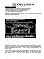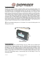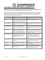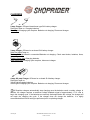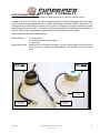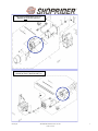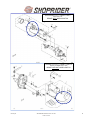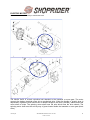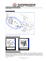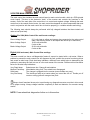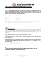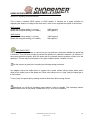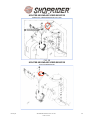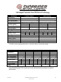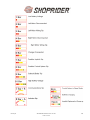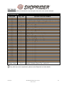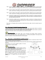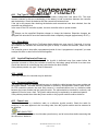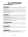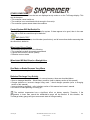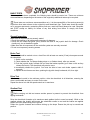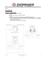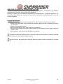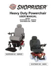
1
GENERAL TECHNICAL SPECIFICATIONS BATTERY A combination of two or more cells electrically connected to work together to produce electric energy. Most Shoprider Powerchairs and Scooters use SEALED LEAD ACID (SLA) BATTERIES. There are two versions of the SLA battery: AGM (Absorbed Glass Mat) or Gel-cell batteries. SLA batteries are rechargeable 12 volt deep cycle batteries. Most Shoprider models use two SLA batteries in series (except the 889-DXD 2-seat model uses four batteries, which is in parallel and series). Shoprider has introduced a new battery technology, Envirofriendly™ battery, which is found in some Shoprider models. Deep cycle batteries are designed to discharge small amounts of current (amps) over a long period of time. They are also designed to be charged-discharged up to 400 cycles when properly maintained and cared for. Due to the improved SLA battery technology, Shoprider uses AGM batteries. This battery has been classified as non-dangerous and is not restricted for transport by air, land, or sea. It is also classified as non-hazardous and is therefore exempt from hazardous material regulations. Because of the way the batteries are defined, Material Safety Data Sheets (MSDS) are a sub-requirement of the Occupational Safety and Health Administration (OSHA) and not required for transport. A copy of the MSDS can be found in this manual. Please note that although considered safe, SLA batteries can be dangerous. SLA batteries contain two toxic elements: Sulfuric Acid and Lead. In addition, Sulfuric acid is highly explosive. When SLA batteries are charged they produce hydrogen gas, which is highly flammable and can cause explosion. Therefore, proper handling is mandatory at all times! Explosion – Improper charging, poor maintenance or battery failure can cause low acid/electrolyte levels, resulting in high concentrations of hydrogen gas and an explosion, although sealed lead acid (SLA) batteries are much less likely to explode. Fire – Dropping a tool or touching a watch or bracelet across the terminals can result in a shock, sparks, smoke, and even an explosion. Pollution – All old SLA batteries must be recycled through an approved source to prevent improper disposal. Improperly disposed SLA batteries can damage the environment, result in major fines and criminal imprisonment. Follow these steps to store SLA batteries: • Always store the batteries FULLY CHARGED • Check batteries once a month and re-charge as needed • When storing a power wheelchair or scooter for more than 2 weeks, charge the batteries and then disconnect them • Avoid hot & cold extremes when storing Always charge batteries completely & test batteries (SLA battery load test and faulty cell check) before beginning any diagnostics for accurate results. NOTE: Load testing SLA batteries is the quickest method of testing batteries. Always charge batteries completely before performing load test. As a general rule, SLA batteries should not drop more than a volt under a 10-second load. v012007jnb SHOPRIDER SERVICE MANUAL 2007 1-800-743-0772 1 CHARGING SLA BATTERIES To properly charge your mobility batteries, follow these simple procedures: • Always use the Shoprider automatic charger for all routine charging • Never run your batteries completely flat (complete discharge) • Don’t “top off” the battery with frequent charges Daily users should charge batteries daily. This applies to anyone who actually uses their equipment for community mobility outside the home. Occasional users should charge batteries before an outing or journey and always after active use (ideally when the battery indicator is at about 50%). Battery Installation: Note: In a multi-battery installation, it is often best to replace the entire set of batteries when one battery is weak or has failed. Series: A “series” system increases the voltage, but keeps the battery capacity (amp hours aka minutes of run time) the same. Therefore, two 12-volt batteries connected in series (POS to NEG, NEG to POS) will deliver 24-volts at the same rating as one battery: During recharge, each battery receives the same amount of current; e.g. if the charger is putting out 3 amps, both batteries are receiving 3 amps. Parallel: A “parallel” system increases the capacity available, but keeps the voltage the same. Therefore, two 12-volt batteries with 35 amp hours (Ah) will deliver 12-volts and 70 Ah (Actually, since each battery’s load is lighter, the reserve capacity will more than double). v012007jnb SHOPRIDER SERVICE MANUAL 2007 1-800-743-0772 2 EnvirofriendlyJ Battery Shoprider, the innovative leader in powered mobility, is the only authorized supplier of the next generation battery, the EnvirofriendlyJ battery (LiFePO4). The EnvirofriendlyJ battery is a new technology that is environmentally safe and user safe due to its inherent nontoxic composition of Lithium Iron Phosphate. The EnvirofriendlyJ battery has a long life, much longer than that of the traditional SLA battery, and offers many benefits over the SLA battery. These benefits include “opportunity charging”, which means you can charge the battery in 5, 10 or 20 minute spurts without damage to the battery. Other benefits include complete discharging without damage, greater cycle charging ability (2000 charge-discharge cycles), and much, much more. The LiFePO4 battery is high energy, which means it doesn’t lose its power during the course of the discharge. The LiFePO4 battery charges quickly, up to 4 times faster than the traditional SLA battery. The EnvirofriendlyJ battery is super lightweight and compact making it an ideal power source for today’s mobility needs. The EnvirofriendlyJ battery pack is a 24-volt pack. Do not open this battery pack or the warranty will be voided. The EnvirofriendlyJ Battery (LiFePO4) 6.25” 9” 2.5” 5.9 lbs total weight Comparing batteries: EnvirofriendlyJ battery has a charge-discharge cycle life of 2000 cycles, the Sealed Lead Acid (SLA) has a charge-discharge cycle life of 200-400 cycles. EnvirofriendlyJ battery averages a 5.5 year life if charged once daily, the Sealed Lead Acid (SLA) averages a 1 year life if charged once daily. Average charge time for EnvirofriendlyJ battery is 2-4 hours, SLA battery is 12-16 hours. EnvirofriendlyJ battery 24-volt pack average weight is 5.9 lbs, SLA battery average weight 2x 12-volt is 50 lbs. EnvirofriendlyJ battery energy density is high, SLA is low. EnvirofriendlyJ battery is environmentally safe, the SLA battery is toxic to the environment (lead). v012007jnb SHOPRIDER SERVICE MANUAL 2007 1-800-743-0772 3 How To/When To Charge Table –EnvirofriendlyJ Battery & SLA Batteries are ready to work in an instant (provided they are charged) and can be used in a reasonably wide temperature range. Charging, on the other hand, has limitations and the user should follow recommended guidelines on how and when to charge. Each battery chemistry has its own charging preference. Batteries behave like humans; some live to a great old age, others die early. Exposure to heat is likely the biggest enemy and the Envirofriendly™ battery has greater tolerances to heat than that of the SLA battery. Steps can be taken to prolong battery life but an ideal world will not be possible. The table below provides basic instruction in maximizing battery performance from cradle to grave. EnvirofriendlyJ Battery Sealed Lead-Acid (AGM or GEL) (LiFePO4) (SLA) How should I prepare my new battery? You can use the EnvirofriendlyJ Battery right away and charge it when needed. Shoprider always recommends charging the battery completely before starting on any journey. SLA comes fully charged. For best result, apply a topping charge to assure full charge. Can I damage my battery if incorrectly prepared? No; EnvirofriendlyJ Battery is forgiving to partial and full charge. No priming is needed when new. Yes; SLA needs a fully saturated charge to keep good performance. A charge can take over 12 hours. Should I use up all battery energy before charging? No, it is better to recharge more often; avoid frequent full discharges. “Opportunity charging” is acceptable & will not damage battery. No, it is better to recharge more often; avoid frequent full discharges. Deep cycles wear down the battery. Use a larger battery if full cycles are required. Should I charge my battery partially or fully? Does not matter. Charging in stages is acceptable. Full charge termination automatically occurs by reading the voltage level and charge current. Charging a full battery is safe and does not cause harm. It is recommended to charge SLA battery in complete, full cycles. Full charge termination automatically occurs by reading the voltage level and charge current. Charging a full battery is safe and does not cause harm. x Should I remove the battery The charger automatically cuts the charge from the charger when full? current when the battery is full. Shoprider recommends removing charger once charging cycle is complete to avoid A/C power surge damage. A float charge of about 2.27V/cell is advisable. Do not allow the open cell voltage to drop below 2.10V/cell while in storage. Shoprider recommends removing charger once charging cycle is complete to avoid A/C power surge damage. Should the battery be kept charged when not in use? State-of-charge is not as important. Do not fully deplete battery. For best results store at 40% charge. IMPORTANT: always keep battery fully charged. A discharged battery causes sulfation (insulating layer in the cell). This condition is often irreversible. Will the battery heat up during charge? No, little heating is generated during charge. Do not allow the battery to heat during charge. No, the battery should remain cool or lukewarm to the touch. The battery must remain cold on maintenance charge. What should I know about chargers? Use Authorized Shoprider Charger only. Charger applies full charge. Fastest fullcharge time: 2-4 hours. Use Authorized Shoprider Charger only. Charge must be fully saturated. Failing to do so will gradually decrease the battery charge capacity. Fastest full-charge time: 8-14 hours. v012007jnb SHOPRIDER SERVICE MANUAL 2007 1-800-743-0772 4 CHARGERS -or2-amp Charger: Off-board transformer type SLA battery charger. Red light=Power on. Charging batteries. Green light=Charging cycle complete. Batteries not charging. Disconnect charger. 3-amp Charger: Off-board or on-board SLA battery charger. Solid Red light=Power on. Flashing Red light=Break in connection/Batteries not charging. Check reset button, batteries, fuses, connections. Flashing Green light=Charging batteries. Solid Green light=Charging cycle complete, disconnect charger. 4-amp & 8-amp Charger: Off-board or on-board SLA battery charger. Red light=Power on. Yellow light=Charging batteries. Green light=Charging cycle complete. Batteries not charging. Disconnect charger. All Shoprider chargers automatically stop charging once the batteries reach a certain voltage. In addition, the charger requires a combined voltage feedback signal of approximately 17-21 volts to begin the charging cycle. If the batteries are severely discharged below this voltage, the charger will not begin the charging the cycle. If the charger does not charge the batteries, it is highly recommended that further testing be performed prior to replacing charger. v012007jnb SHOPRIDER SERVICE MANUAL 2007 1-800-743-0772 5 ELECTROMAGNETIC BRAKE Brake designed to lock the motor upon release of accelerator (throttle or joystick) to prevent roll-away. Located at the end of the motor, the electromagnetic brake automatically disengages the motor shaft, when it receives the appropriate amount of voltage. This happens when the throttle is depressed. The clicking sound you hear when the throttle lever or joystick is engaged is the brake releasing the motor shaft allowing the motor to spin. The brake will not re-engage until the throttle/joystick is released all the way. There is also a slight delay programmed into the controller for smooth stops. Electromagnetic brake multi-meter readings: Brake Solenoid Brake Micro-switch 42-65 Ω (ohms) 22-24 volts at throttle (acceleration) 0 volts at idle Basically an on/off switch controlled by a lever. When testing, you should have either an open or closed circuit depending on the position of the free wheel lever. Brake with Micro-switch Brake without Micro-switch Brake Solenoid connector Brake Solenoid connector v012007jnb Micro-switch connector SHOPRIDER SERVICE MANUAL 2007 1-800-743-0772 6 PWC Jetstream #888WAM/WAL Drive Train BRAKE WITH MICRO-SWITCH PWC 6Runner #888WNLM/WNLL Drive Train BRAKE WITHOUT MICRO-SWITCH v012007jnb SHOPRIDER SERVICE MANUAL 2007 1-800-743-0772 7 SCOOTER Dasher 3 or 4 or 9 #GK8-3 or GK8 or GK73 Drive Train BRAKE WITH MICRO-SWITCH SCOOTER Sunrunner 3 or 4 #888B-3 or 888B-4 or Sprinter XL4 #889B-4 Drive Train BRAKE WITHOUT MICRO-SWITCH v012007jnb SHOPRIDER SERVICE MANUAL 2007 1-800-743-0772 8 ELECTRIC MOTOR A motor that converts electricity to mechanical work The electric motor is a black cylindrical unit attached to the transaxle or worm gear. The motor converts the battery electrical power into a mechanical drive. When the throttle or joystick lever is depressed it signals the main control box to release voltage to the motor (& brake), which causes the motor shaft to rotate. The spinning motor shaft turns the axle which turns the drive wheels. The spinning motor shaft turns the axle by way of gears located inside the transaxle or worm gear (direct drive). v012007jnb SHOPRIDER SERVICE MANUAL 2007 1-800-743-0772 9 Electric motor multi-meter readings: Motor <1.0 Ω (ohms) 18-24 volts at throttle (voltage may vary slightly) 0 volts at idle If the motor has high resistance greater than 1 ohm (Ω), check the motor brushes (2 per motor) for wear and clean or replace as needed. Shoprider motors have four different types of connections to the transaxle or worm gear. Please refer to the picture below. #1 is a worm gear style 1995 and older unsealed motor/transaxle. #2 is the most common type motor connector with a red or white plastic coupling with metal bar key. #3 is called a “propeller shaft” connector found on the 2001/2002 style PWC motor/worm gear and 9XL type motors. The 7um motor pictured on the left is found on most compact scooters and power wheelchairs. v012007jnb SHOPRIDER SERVICE MANUAL 2007 1-800-743-0772 10 TRANSAXLES AND WORM GEARS A unit combining the transmission and differential of a powered vehicle and connected directly to the axles of the driving wheels. SCOOTER TRANSAXLE POWER WHEELCHAIR WORM GEAR 2000 & older 2003 & newer 2001-2002 style TRANSAXLES AND WORM GEARS There are breather caps (that look like grease fittings) found on many Shoprider worm gears and transaxles. These are designed only to allow for air transfer due to heating and cooling. No grease, oil or lubricant should ever be put into this fitting. WD-40 should never be used on any part on any Shoprider®, at any time. v012007jnb SHOPRIDER SERVICE MANUAL 2007 1-800-743-0772 11 SCOOTER MAIN CONTROL BOX The main control box includes the main control board or main control module, which is a PCB (printed circuit board). This box is the electronic “brain” of the scooter and controls the functions of the scooter. One of the main jobs of the control box is to control and regulate voltage. Although the main control box is the central control center, the main control box depends on other components that must work in conjunction with the main control box to function properly (i.e. variable resistors and wiring). The following tests should always be performed with fully charged batteries that have tested well under a load (load test). Analog (Pre 2004) Main Control Box multi-meter readings: Direct Voltage Output Motor Voltage Output Brake Voltage Output 9-11 volts (test at yellow and orange wire connected to the main control cable, test with key switch on and speed dial turned up to maximum) 18-24 volts at throttle 0 volts at idle 22-24 volts at throttle 0 volts at idle Digital (2004 and newer) Main Control Box readings: This main control box has a self-diagnostics feature & cannot be tested with a volt meter. When a problem is present the main control box will diagnose the fault, prohibit the scooter from being driven and sound an alert beep. Each alert beep indicates a different issue which helps to determining the problem by narrowing the fault into one of a few main areas of the scooter. Reference this information below for the alert beep indications. Very Rapid beepMedium Fast beepSolid beepVery Slow beep- Batteries are low. Charge & test batteries. Motor/brake wiring fault. Free wheel lever disengaged. The charger is plugged into the scooter (some models may vary). The throttle pot was not at center when you turned the unit on. Throttle pot off center or wiring (yellow & orange wires) fault. Always check freewheel levers prior to performing any diagnostics-scooter must be in drive mode to do proper testing. Always charge batteries completely & load test batteries for accurate testing results. NOTE: Power wheelchair diagnostics further on in this section. v012007jnb SHOPRIDER SERVICE MANUAL 2007 1-800-743-0772 12 THROTTLE POTENTIOMETER VARIABLE RESISTOR (throttle pot) Resistor for regulating current aka accelerator This is a centered 5K Ω variable resistor. It controls the voltage to the motor by regulating varying voltage to either the positive or negative connections in the main controller. It is very easy to short out the main controller when testing the throttle pot. Be sure that when you test it, you first disconnect the connector from the main control cable (when applicable). Yellow to orange (Outside to outside) 5KΩ (approx) White to yellow 2.5KΩ (approx) White to orange 2.5KΩ (approx) The throttle pot is housed in the tiller assy. To test the throttle pot you need to open the tiller assy to gain access to the 3 wires (yellow, white, and orange) that are soldered onto it. SMP QUICK TEST The following testing procedure is a quick test you may perform to determine whether the throttle pot is defective. This procedure simply by-passes the throttle pot to determine whether it is defective. If the scooter performs properly when the throttle pot is by-passed then the problem is likely to be the throttle pot. Put the scooter on jacks prior to starting the following testing procedure. Turn scooter on first before making contact on the wires otherwise the test will not work (safety feature will interfere). After the scooter is turned on, use alligator clips at the solder joints or a paper clip to make contact with the wires in the backside of the throttle pot assy connector. Either is an effective tool to “jump” (test) the throttle pot. Make contact at the WHITE and YELLOW wires. Doing so may cause the scooter to drive forward. Jumping the WHITE and ORANGE wires may make the scooter drive backward. If the scooter now drives when the throttle pot is jumped, the throttle pot likely needs to be replaced. CAUTION: DO NOT JUMP ALL 3 WIRES TOGETHER! DOING SO MAY RESULT IN PERMANENT DAMAGE TO THE MAIN CONTROL BOX. v012007jnb SHOPRIDER SERVICE MANUAL 2007 1-800-743-0772 13 SPEED POTENTIOMETER VARIABLE RESISTOR (speed pot) Resistor for regulating current aka rheostat This is either a variable 25KΩ resistor or 10KΩ resistor. It functions as a speed controller by regulating the amount of voltage to the drive motor, which in turn regulates the speed of the scooter. 25KΩ resistor Speed dial at lowest setting (1 or turtle) Speed dial at highest setting (10 or rabbit) 25KΩ (approx) 0KΩ (approx) 10KΩ resistor Speed dial at lowest setting (1 or turtle) Speed dial at highest setting (10 or rabbit) 10KΩ (approx) 0KΩ (approx) SMP QUICK TEST The following testing procedure is a quick test you may perform to determine whether the speed pot is defective. This procedure simply by-passes the speed pot to determine whether it is defective. If the scooter performs properly when the speed pot is by-passed then the problem is likely to be the speed pot. This test may be performed on any type of speed resistor, variable or in-line. Put the scooter on jacks prior to starting the following testing procedure. Use alligator clips at the solder joints or a paper clip to make contact with the wires (black and/or white) at the solder joints of the speed pot. Either is an effective tool to “jump” (test) the speed pot or in-line resistor. To test, “jump” the speed pot by making contact at both wires while running scooter. Sometimes you will find a secondary speed resistor, in-line or variable. This secondary resistor will be located in one of two places. Please refer to Fig. 1A & 1B for reference. v012007jnb SHOPRIDER SERVICE MANUAL 2007 1-800-743-0772 14 FIG. 1A SCOOTER SECONDARY SPEED RESISTOR (SPEED POT VARIABLE RESISTOR 10K or 25K) PRIMARY SPEED POT FIG. 1B SCOOTER SECONDARY SPEED RESISTOR (10K IN-LINE RESISTOR) v012007jnb SHOPRIDER SERVICE MANUAL 2007 1-800-743-0772 15 SCOOTER TROUBLESHOOTING Power wheelchair diagnostics begin on page 19 UNIT LIGHTS UP/HORN WORKS BUT UNIT WILL NOT MOVE This is a common technical call because this occurs when the free wheel lever is not in drive mode. You will automatically know since the lights light up and horn works that there is not a problem with the power source loop. If you hear a beeping noise, please refer to the SCOOTER MAIN CONTROL BOX section, DIGITAL MAIN CONTROL BOX. The beeping you hear is a fault beep indicating the scooter main control box has detected a problem. For pre-2004 models (Analog Main Control Box) do the following voltage outputs tests beginning with the direct voltage output test. If it’s not less than 9 volts, check to see if the brake is getting power. If it is pull the brake off the end of the motor. When you do this you should leave the connections going to the brake connected (if there is a micro-switch there will be two connections, if not only one). Now run the unit. If the brake was the problem, the unit will work fine now (caution, now there is no brake while unit is standing still). Check freewheel lever - Are wheels locked? Put lever in correct position, turn unit off and back on to reset (only necessary for units with micro-switches). If OK… Check batteries with load tester - If either battery drops more than 1 volt under a load, the battery(s) are bad. Replace “both” batteries. If OK… Check direct voltage output from main control box - Set multi-meter to DC (direct current voltage), put one probe at yellow wire and one probe at orange wire behind front to rear cable connector on main control box side. Readings should be at least 9 volts. If OK… Check voltage to brake - Set multi-meter to DC and put probes behind brake solenoid connector, one at each wire or put probes behind the motor connector at the smaller gauge wires (larger gauge wires are the motor wires). Throttle unit forward all the way, you should read 22-24 volts. If OK… Check voltage to motor - Set multi-meter to DC and put probes behind motor connector, one at each of the larger gauge wires (smaller gauge wires are the brake solenoid wires). Throttle unit forward all the way, you should read at least 18 volts; sometimes you may read as low as 13 volts (low batteries). If OK… Check brake micro-switch (if unit is equipped) - Unplug micro-switch connector and run unit to see if problem recurs. Note: problem may be in the brake free-wheel lever. If OK… Remove brake assy from motor and run unit - Does motor spin freely? If motor doesn’t spin, the problem is likely the motor. If motor does spin, the problem is likely in the brake assy. If OK… v012007jnb SHOPRIDER SERVICE MANUAL 2007 1-800-743-0772 16 Verify wiring at solder joints - At the speed potentiometer and throttle potentiometer. If OK… Check Throttle potentiometer - On rare occasions, the throttle pot may become off-center causing the unit not to function (this is a built in safety feature). Test the resistance (ohms) on either side to verify they are equal (refer to throttle pot section). Unplug the throttle pot connector from the upper wire harness and put one probe in the back of the connector at the orange wire and one at the white wire. The reading should be around 2.5k. Remove the probe from the orange wire and put it in at the yellow wire. The reading should be around 2.5k. If the two readings are not equal within a few tenths, there may be a problem with throttle pot assy. If OK… Check continuity on main wire harness - The main wiring harness connects the tiller controls to the main control box. Sometimes the wiring at the base of the tiller where a zip tie secures the wiring harness to the handlebar column may get a break in a wire. This is a stress point because the harness is tied down, constant turning of the tiller, and the harness also makes a 90 degree turn from down to back. So when checking continuity, try wiggling the wires at this point of reference throughout the testing. UNIT WILL NOT TURN ON This is a power problem known as a power source or power source loop problem. A power source problem would be between the batteries and the main controller, or from the key to the main controller. First check the circuit breaker/reset button and the in-line fuses coming off of each battery. It is important to note here that the most common reason for blown fuses, for scooters, is loose connections on the battery terminals. Push the reset button (circuit breaker). Check for loose connections and wiring. Verify battery terminal connections are tight. Check the in line fuses located on the battery cables (one for each battery). Load test batteries. If either battery drops more than 1 volt under load, replace “both” batteries (you should never replace just one battery). Use meter to see if power is going to the key switch. Key switch can be checked by jumping the blue and brown wires before the key switch. Check the wiring to the black and red connectors that go to the main controller. NOTE: If the batteries have just been changed, check that the black battery cable wires are connected to the minus terminal and that the red wires are connected to the positive terminal. If they are reversed you would have the same symptom of unit showing no power. UNIT CUTS OUT WHILE DRIVING By far the most difficult problem to diagnose is an intermittent problem. Most times the problem must occur in order to locate it. Sometimes you do have some clues. Test drive the unit to find out if the unit shuts off when hitting a bump or maybe even when turning. If the unit turns off whenever it turns right, the problem is most likely the front to rear cable. After checking for loose connections or wiring, the first place to start is to test continuity. Continuity is a method of testing the wiring via a multimeter. The most common way to test continuity is by ohms !, however, occasionally the test result shows v012007jnb SHOPRIDER SERVICE MANUAL 2007 1-800-743-0772 17 good even though there is a defective wire. Another way to test continuity is by voltage. This is done by verifying equal voltage at either end of each wire. SCOOTER HAS REDUCED POWER, LIMITED SPEED AND RANGE Possible Cause: One or both batteries are defective-check batteries and replace both batteries if necessary. Insufficient charging time, batteries are not fully charged. Batteries are not receiving charge (low battery voltage). Cable connectors not making proper contact, corrosion or bad connection at battery terminals. ERRATIC THROTTLE CONTROL, SURGING OR HESITATION Possible Cause: Faulty throttle potentiometer. Faulty speed potentiometer. Loose connections or battery terminals. Worn or dirty motor carbon brushes, or carbon brush spring. CIRCUIT BREAKER TRIPS FREQUENTLY Possible Cause: Overload caused by excessive demand on motors (low tire pressure, sticky brake, seized wheel bearings, etc). Heavy load on steep incline. Loose batteries terminal connections. REDUCED BRAKING POWER, SLIPPING ON INCLINE Possible Cause: Brake worn out/weak brake. Faulty main control box (analog main control boxes only). v012007jnb SHOPRIDER SERVICE MANUAL 2007 1-800-743-0772 18 THE SHOPRIDER POWER WHEELCHAIR Joystick Controller (PG Drives Technology VSI) The VSI is an integral control system. 8 1. On-Off Button: This button turns the joystick controller (hereinafter referred to as VSI) on and off. Do not use 2 1 this button to stop the power chair, except in an emergency. 2. Battery Gauge/Fault Indicator: This is a 10-segment 4 3 TruCharge display, which indicates if the VSI is switched on and gives the state of charge of the battery. Additionally, any faults in the Powerchair electrical 5 6 system are also indicated by this display. 3. Maximum Speed Indicator: This is a 5-segment display, which indicates the maximum speed setting selected. 7 4. Horn Button: This button operates the Powerchair’s horn. 5. Speed Decrease Button: This button decreases the maximum speed. Or this can be used to select a profile*. 6. Speed Increase Button: This Button Increases the maximum speed. Or this can be used to select a profile*. 7. Joystick: This controls the speed and direction of the Powerchair. Push the joystick in the direction you want to go. The further you push it, the faster the speed will be up to the pre-selected speed setting. Releasing the joystick will automatically engage the brakes and stop the Powerchair smoothly. A fast brake-rate has been programmed for emergency stopping, simply pull joystick into reverse to stop quickly. 8. Charging Port: This is the primary charging port for Shoprider PWCs with off-board chargers. This is a secondary charger port for Shoprider PWCs equipped with on-board chargers. When using this charging port only plug into this port with the qualified Shoprider charger certified by the original manufacturer of the Powerchair. This port should not be used as a power supply for any other electrical devices. Doing either of these as stated above will void the warranty of the Powerchair. *Profiles are preprogrammed settings you can program into the joystick controller to meet the individual needs of the user. A PG Drives Technology PP1a Programmer or PC Programmer is required to program the controller. Shoprider recommends that every power wheelchair be programmed to meet the needs of the individual user. This may be done using a PG Drives Technology PP1a Programmer. Please contact Shoprider Mobility Products, Inc to purchase a PG Drives Technology PP1a Programmer. The VSI controller can be fitted to suit either right or left-handed users. Please refer to the Model User Manual or contact Shoprider Mobility Products, Inc. v012007jnb SHOPRIDER SERVICE MANUAL 2007 1-800-743-0772 19 OTHER VSI FEATURES LOCK MODE: The VSI controller, when preprogrammed with lock mode turned on, can be locked to prevent unauthorized use. The locking method is achieved through a sequence of key presses and joystick movements, as detailed below. To lock Powerchair controller: While the controller is switched on, depress and hold the on/off button. After 1 second the controller will bleep. Now release the on/off button. Push the joystick forward until the controller bleeps. Push the joystick in reverse until the controller bleeps. Release the joystick, there will be a long bleep. The Powerchair controller is now locked. To unlock the Powerchair controller: Use the on/off button to switch the controller on. The maximum speed/profile indicator will be rippling up and down. Push the joystick forward until the controller bleeps. Push the joystick in reverse until the controller bleeps. Release the joystick, there will be a long bleep. The Powerchair is now unlocked. SLEEP MODE: If the controller is left on and not used for up to ten minutes, the controller will automatically “go to sleep”. This is recognized by a slow intermittent flash of the battery indicator lights. Simply turn the controller off and back on to reset. v012007jnb SHOPRIDER SERVICE MANUAL 2007 1-800-743-0772 20 CONTROLLER PROGRAMMING SHEET VSI Integral Controller from PG Drives Technology Parameter Acceleration¹ Deceleration¹ Turn Acceleration¹ Turn Deceleration¹ Factory Setting User Settings % % % % % % % Maximum Forward Speed¹ Reverse Speed¹ Turning Speed¹ Power¹ Sleep Timer % Minimum Maximum Minimum % % % % % % % % % % % % % Minutes Fwd Joystick Throw Rev % Left % Right % % Minutes Fwd % Rev % Left % Right % % Steer Correct Switch Bleep Switch Volume Speed Adjust Profiles ¹ If Profile is set to anything other than ’0’, use below chart to record user settings. Parameter Acceleration Profile 1 Forward Speed Reverse Speed Turning Speed Power Profile 2 % % % % Deceleration Turn Acceleration Turn Deceleration Max % % % User Settings Profile 3 Min % % % % % % % % Max % % % Min % % % % Profile 4 % % % % Max % % % Min % % % % Profile 5 % % % % Max % % % Min % % % % % % % % Max % % % Min % % % % Note: Each Shoprider PWC model has its own individual factory settings for optimum performance. v012007jnb SHOPRIDER SERVICE MANUAL 2007 1-800-743-0772 21 INTRODUCTION TO CONTROLLER DIAGNOSTICS The primary objective of this guide, developed by PG Drives Technology (PGDT), is to assist service technicians in finding the likely area of a detected fault within the whole wheelchair electrical system. It is important to realize that even though the control system is signaling a fault, it may not be the control system itself that is defective. This is because the control system is able to detect general problems in other electrical components (motors, batteries, brake microswitches, etc) or the wiring to these components. When a control system has detected a fault a system trip is indicated known as a fault code. This guide covers diagnostics of Shoprider power wheelchairs fitted with PGDT VSI & VR2 controllers, in addition to the PGDT Pilot. For basic diagnostic capability it is not necessary to have a programmer to use this guide, as all these control systems have a sophisticated level of on-board diagnostics. Using this guide, it is possible to define a trip as belonging to one of 12 types. Once this type has been established, there are suggestions as to what the possible cause may be. The guide should only be used to decide the starting point of your own diagnosis, as it is possible for the controller to indicate a fault in another component even though the controller itself may be defective. Nevertheless, experience has shown that loosened connectors and wiring are common causes of electrical problems, so it is necessary to examine these more vulnerable areas first. Diagnostics should only be conducted by service technicians with in-depth knowledge of the PGDT electronic controllers. An incorrect or badly effected repair could result in an unsafe set-up of a wheelchair. Shoprider and PGDT accept no liability for losses of any kind arising from an incorrect or badly effected repair. CONTROLLER DIAGNOSTICS PROCESS For efficient and effective diagnosis the following basic steps should be taken. • Establish the type of control system fitted to the power wheelchair. Shoprider’s current power wheelchair models use the PGDT VSI controller, all except the Shoprider HD model #888WHD, which is fitted with the PGDT VR2 controller. Note: 2002 and older Shoprider models were fitted with the PGDT Pilot controller. • Confirm there is a trip, or has been an intermittent trip. Refer to next section, “Detecting a Trip Has Occurred”. • Establish the trip type. Refer to section, “Trip Diagnosis”. • Refer to the relevant trip table for the controller you are working with i.e. VSI, VR2, etc. • Refer to the possible cause as indicated by the trip table, and carry out recommended investigative and corrective action. Refer to section, “Trip Types and Their Possible Causes”. v012007jnb SHOPRIDER SERVICE MANUAL 2007 1-800-743-0772 22 DETECTING A TRIP HAS OCCURRED Firstly observe the controller’s battery gauge (TruCharge) display. This will display as described in one of the following. Flashing Rapidly The controller system is tripped. To determine the trip type, refer to the next section, “Trip Types and Their Possible Causes”. Connecting a programmer to the controller while this is happening will give you a trip code. Flashing Slowly No trip is currently detected by the control system. The slow flash is an indication that the batteries require charging. A trip code may have occurred previously and may be stored in the controller system’s diagnostic log. This log is obtainable only with a programmer. Display is Steady No trip is currently detected by the controller system. A trip code may have occurred previously and may be stored in the controller system’s diagnostic log. This log is obtainable only with a programmer. Display Does Not Illuminate No power is reaching the controller system. Ensure the batteries are fully charged and that all connections between batteries and controller are made. If batteries, connections, and wiring are good, then the control system may be defective. TRIP DIAGNOSIS There are two methods of trip diagnosis. Trip Diagnosis with the TruCharge The following diagrams show you how to read the TruCharge battery gauge in the event of a controller system trip. Please note that on VSI & VR2 controllers the TruCharge reads left to right, on the Pilot controller the TruCharge reads bottom to top. Please refer to the following page for the Trip Diagnosis with the TruCharge. Using a Programmer to Read the Trip Code If you connect a programmer while the TruCharge is flashing rapidly, then a four digit trip code will be displayed. The trip code can be referred to the trip types using the trip tables, depending on the type of controller you are working with. You must connect the programmer to the control system after the TruCharge display has started flashing. If the programmer is already connected when the flashing commences the trip code will not be displayed. TRIP DAIGNOSTICS WITH TruCharge DISPLAY v012007jnb SHOPRIDER SERVICE MANUAL 2007 1-800-743-0772 23 v012007jnb SHOPRIDER SERVICE MANUAL 2007 1-800-743-0772 24 TRIP TABLES Use the following tables to determine the trip description then refer to the section indicated. VSI CONTROLLER TRIP CODE 0A00 1500 1501 1502 1600 1E03 1E04 1E05 2C00 2F00 3000 3B00 3C00 3D00 3D01 3E00 3E01 4401 7163 7164 716B 716C 716E 716F 7170 7173 7174 7175 7A00 7A02 7A03 TRIP TYPE Blink 9 9 9 10 Charging 6 6 1 User 7 2 4 3 3 5 5 8 8 8 8 8 8 8 8 8 8 8 8 8 8 All Other Codes 7 or 8 DESCRIPTION & REFERENCE Refer to section A11 Solenoid (Micro-switch) Brake Trip – section A9 Short Circuit in Solenoid (Micro-switch) Brake Circuit - section A9 Open Circuit in Solenoid (Micro-switch) Brake Circuit - section A9 High Battery Voltage – section A10 Refer to section A25 Refer to section A26 Refer to section A27 Low Battery Voltage – section A1 Refer to sections A7 & A12 Refer to section A17 Left Motor Disconnected – section A2 Right Motor Disconnected – section A4 Left Motor Wiring Trip – section A3 Left Motor Wiring Trip – section A3 Right Motor Wiring Trip – section A5 Right Motor Wiring Trip – section A5 Refer to section A8 Refer to section A16 Refer to section A16 Refer to section A16 Refer to section A16 Refer to section A16 Refer to section A16 Refer to section A16 Refer to section A16 Refer to section A16 Refer to section A16 Refer to section A28 Refer to section A29 Refer to section A29 Possible Joystick Trip – section A7 Possible Controller System Trip – section A8 If any other trip code is experienced, please contact Shoprider for further details. v012007jnb SHOPRIDER SERVICE MANUAL 2007 1-800-743-0772 25 VR2 CONTROLLER TRIP CODE 1320 1505 1506 1600 1E03 1E04 1E05 2C00 2C02 2F00 3B00 3C00 3D00 3D01 3E00 3E01 4401 5400 7A02 7100 7101 7102 7103 7104 7902 TRIP TYPE 9 9 10 Charging 6 Charging 1 User 2 4 3 3 5 5 8 7+S¹ A only ² 7 7 7 7 7 - All Other Codes 7 or 8 DESCRIPTION & REFERENCE Refer to section A28 Left Solenoid (Micro-switch) Brake Trip – section A9 Right Solenoid (Micro-switch) Brake Trip – section A9 High Battery Voltage – section A10 Refer to section A6 Refer to section A25 Refer to section A26 Low Battery Voltage – section A1 Low Battery Lockout – section A1 Refer to section A7 & A12 Left Motor Disconnected – section A2 Right Motor Disconnected – section A4 Left Motor Wiring Trip – section A3 Left Motor Wiring Trip – section A3 Right Motor Wiring Trip – section A5 Right Motor Wiring Trip – section A5 Control System Trip – section A8 Communications Trip – A14 Actuator Motor Wiring Trip – section A27 Joystick Trip – section A7 Joystick Trip – section A7 Joystick Trip – section A7 Joystick Trip – section A7 Joystick Trip – section A7 Refer to section A29 Possible Joystick Trip – section A7 Possible Controller System Trip – section A8 If any other trip code is experienced, please contact Shoprider for further details. v012007jnb SHOPRIDER SERVICE MANUAL 2007 1-800-743-0772 26 PILOT CONTROLLER TRIP CODE 0A00 1500 1504 1600 1E00 2C00 2F00 3B00 3C00 3D00 3D01 3E00 3E01 TRIP TYPE Blink 9 9 10 6 1 User 2 4 3 3 5 5 All Other Codes 7 or 8 DESCRIPTION & REFERENCE Refer to section A11 Solenoid (Micro-switch) Brake Trip – section A9 Solenoid (Micro-switch) Brake Trip - section A9 High Battery Voltage – section A10 Charger Connected (when applicable) - section A6 Low Battery Voltage – section A1 Refer to sections A7 & A12 Left Motor Disconnected – section A2 Right Motor Disconnected – section A4 Left Motor Wiring Trip – section A3 Left Motor Wiring Trip – section A3 Right Motor Wiring Trip – section A5 Right Motor Wiring Trip – section A5 Possible Joystick Trip – section A7 Possible Controller System Trip – section A8 If any other trip code is experienced, please contact Shoprider for further details. v012007jnb SHOPRIDER SERVICE MANUAL 2007 1-800-743-0772 27 TRIP TYPES & THEIR POSSIBLE CAUSES Once the trip type has been established, refer to the relevant section below for further information. A1 Trip Type 1 – Low Battery Voltage This occurs when the controller detects that the battery voltage has fallen below 16v. Check the condition of the batteries and the connections to the controller. If the trip is still present after the batteries and connections, including wiring, have been checked, then controller may be defective. Note: In the case of the VR2 system, the term controller refers to the power module. 2C02 The VR2 controller system is making a log of the times that the Low Battery Lockout has been initiated. SMP QUICK TEST Using a car 12v battery boost charger with tester, test each battery for defect. Refer to battery section of this manual for details. A2 Trip Type 2 – Left Motor Disconnected This occurs when the controller detects that the left hand motor (when sitting in the chair) has become disconnected. Check the left hand motor, motor connectors and wiring. If the trip is still present after the above checks have been made, then the controller may be defective. Note: In the case of the VR2 system, the term controller refers to the power module. SMP QUICK TEST Swap motor connectors, plugging the left side (white) into the right side (green) and right side into left side. Turn controller back on. If the 2 bars continue to flash then the problem is either the wiring harness or the controller. If 4 bars now flash then the problem is in the motor. A3 Trip Type 3 – Left Motor Wiring Trip This occurs when the controller detects a fault in the wiring to the left hand motor (when sitting in the chair), in particular if a motor connection has short-circuited to a battery connection. Check the left hand motor connectors and wiring. If the trip is still present after the above checks have been made, then the controller may be defective. Note: In the case of the VR2 system, the term controller refers to the power module. SMP QUICK TEST Swap motor connectors, plugging the left side (white) into the right side (green) and right side into left side. Turn controller back on. If the 3 bars continue to flash then the problem is either the wiring harness or the controller. If 5 bars now flash then the problem is in the motor. A4 Trip Type 4 – Right Motor Disconnected This occurs when the controller detects that the right hand motor (when sitting in the chair) has become disconnected. Check the right hand motor, motor connectors and wiring. If the trip is still present after the above checks have been made, then the controller may be defective. Note: In the case of the VR2 system, the term controller refers to the power module. v012007jnb SHOPRIDER SERVICE MANUAL 2007 1-800-743-0772 28 SMP QUICK TEST Swap motor connectors, plugging the left side (white) into the right side (green) and right side into left side. Turn controller back on. If the 4 bars continue to flash then the problem is either the wiring harness or the controller. If 2 bars now flash then the problem is in the motor. A5 Trip Type 5 – Right Motor Wiring Trip This occurs when the controller detects a fault in the wiring to the right hand motor (when sitting in the chair), in particular if a motor connection has short-circuited to a battery connection. Check the right hand motor connectors and wiring. If the trip is still present after the above checks have been made, then the controller may be defective. Note: In the case of the VR2 system, the term controller refers to the power module. SMP QUICK TEST Swap motor connectors, plugging the left side (white) into the right side (green) and right side into left side. Turn controller back on. If the 5 bars continue to flash then the problem is either the wiring harness or the controller. If 3 bars now flash then the problem is in the motor. A6 Trip Type 6 – Charger Connected This occurs when the controller detects that an off-board charger is connected. Check that the battery charger is disconnected. If the trip is still present after the above checks have been made, then the controller may be defective. Note: In the case of the VR2 system, the term controller refers to the joystick module. A7 Trip Type 7 – Possible Joystick Trip If you are working with a VSI or Pilot controller, this occurs if the controller detects a problem within its own joystick. The joystick can only be replaced by an authorized person. If you are working with a VR2 system, this occurs of there is a problem detected in the joystick module, or there is a communications error between the joystick module and power module. Note: A communications error is indicated by the amber LEDs below the TruCharge display flashing. This flash pattern may only occur for a few seconds before the system automatically powers down. The pattern can be re-observed by powering up the system again. • If the LEDs are flashing then the most likely cause of the problem is the cable between the joystick module and power module. The cable should only be repaired by an authorized person. • If the LEDs are not flashing, then the most likely cause of the problem is the joystick module. The joystick module can only be repaired by an authorized person. SMP QUICK TEST Turn controller off & stir the joystick like a spoon in a pot. Is the rotation smooth or choppy? If the rotation is not smooth, the joystick is likely bent or damaged. If you are working with a VR2 controller system, this occurs if the control system detects a problem within its own joystick, or there is a communications error between the joystick module and power module. v012007jnb SHOPRIDER SERVICE MANUAL 2007 1-800-743-0772 29 7100 Loss of comms to the joystick, check the joystick cable. Problem may be in joystick ribbon cable, connections or mating sockets and may only be checked by authorized technicians. 7101 Loss of comms to the joystick, check the joystick cable. Problem may be in joystick ribbon cable, connections or mating sockets and may only be checked by authorized technicians. 7102 Loss of comms to the joystick, check the joystick cable. Problem may be in joystick ribbon cable, connections or mating sockets and may only be checked by authorized technicians. 7103 Internal trip, problem may be in joystick ribbon cable, connections or mating sockets and may only be checked by authorized technicians. Ensure the cable is connected correctly to both the joystick and the PCB. 7104 Internal trip, problem may be in joystick ribbon cable, connections or mating sockets and may only be checked by authorized technicians. Ensure the cable is connected correctly to both the joystick and the PCB. If the trip is still present after the above checks have been made, then the joystick may be defective. A8 Trip Type 8 – Possible Controller System Trip If you are working with a VSI or Pilot controller, this occurs if the control system detects a problem within itself. The VSI or Pilot can only be repaired by an authorized person. If you are working with the VR2 control system, this occurs of the power module detects a problem within itself. The power module can be repaired by an authorized person. SMP QUICK TEST Turn controller off, unplug main wiring cable, motor connectors and battery cable connectors. Reconnect all connectors firmly. Turn controller back on. Is the trip still present? If the trip is still present the problem is likely internal within the control system. A9 Trip Type 9 – Solenoid Brake Trip (Micro-switch) This occurs when the controller detects a problem in the brake system or connectors to them. Check these connections and the micro-switches. If the trip is still present after the above checks have been made, then the controller system may be defective. In the case of the VR2 controller system, the term controller refers to power module. SMP QUICK TEST Confirm that each micro-switch performs properly, that the nipple goes in when pushed by the free-wheel lever and goes out when released by the free-wheel lever. If the micro-switches are good, test the 12v brake loop wiring at the female connector end of the wiring harness. Refer to diagram on right. You should read approximately 24v at #1 & either #2 or #3 port. If you do not read any voltage, then it is possible that the wiring harness is defective. v012007jnb SHOPRIDER SERVICE MANUAL 2007 1-800-743-0772 2 3 1 30 A10 Trip Type 10 – High Battery Voltage This occurs when the controller detects that the battery voltage has risen above 35v. The most common reasons for this are overcharging of the battery or bad connections between the controller and the batteries. Check the batteries and the connections between them. If the trip is still present after checking the batteries and connections have been checked, then the controller may be defective. In the case of the VR2 controller system, the term controller refers to power module. Always use the specified Shoprider charger to charge the batteries. Shoprider chargers are equipped with auto-shutoff once the batteries have been completely charged (approximately 26-27v). A11 Sleep Mode This condition is indicated by the TruCharge display blinking on once every 2.5 seconds. It is not a trip condition, but indicates the controller has gone to sleep. To awake the controller, switch off and on again. The controller goes to sleep after a programmed period of time. A programmer is required if you want to adjust this time or remove this function altogether. A12 Joystick Displaced at Power-up The most common cause of this trip is if the joystick is deflected away from center before the controller is turned on. When the controller is turned on, the battery gauge will blink for a short time. Check that the user in not deflecting the joystick before the blink finishes. If the problem persists, trip type 7 must be assumed. A13 Inhibit If this trip is present, the controller may be defective. A14 Communications Error The most likely cause of a communications error is a defective cable between the power module and the joystick module. The cable should be checked for continuity, and replaced if found to have a fault. On VR2 controller systems, the most likely cause of a communications error is a defective cable between the power module and the joystick module. The cable should be checked for continuity, and replaced if found to have a fault. The joystick cable can only be replaced by an authorized person. If the problem persists then either the power module or the joystick module could be defective. A15 Power Loss This can be caused by a defective cable or a defective joystick module. Check the cable for continuity. If the cable appears to be in working order, then the joystick module must be assumed to be defective. SMP QUICK TEST Always check batteries, fuses, circuit breaker (reset button), and all connections before assuming that the controller is defective. v012007jnb SHOPRIDER SERVICE MANUAL 2007 1-800-743-0772 31 A16 Dual Attendant Module Trip The power module or the joystick module could be defective. A25 Inhibit 2 Active In the case of a VSI, inhibit 2 input is active. The inhibit 2 input is via the blue 2 way connector and is normally associated with actuator functions. The operation if inhibit 2 will depend on the programmed settings of the VSI. Check all wiring and switches connected to inhibit 2. If these appear to be in working order, then the controller may be defective. In the case of a VR2, inhibit 2 input is active. The inhibit 2 input is via the INH-2 way connector and is normally associated with speed limit or actuator inhibit functions. The operation of the inhibit 2 will depend on the programmed settings of the VR2. Check all wiring and switches connected to inhibit 2. If these appear to be in working order, then the power module may be defective. A26 Inhibit 3 Active In the case of a VSI, inhibit 3 input is active. The inhibit 3 input is via the 3 way on-board charger and is normally associated with this function. The operation of the inhibit 3 will depend on the programmed settings of the VSI. Check all wiring, switches and on-board charger (if fitted) connected to inhibit 3. If these appear to be in working order, then the VSI may be defective. In the case of a VR2, inhibit 3 input is active. The inhibit 3 input is via the 3 way on-board charger and is normally associated with this function. The operation of the inhibit 3 will depend on the programmed settings of the VR2. Check all wiring, switches and on-board charger (if fitted) connected to inhibit 3. If these appear to be in working order, then the power module may be defective A27 Actuator Motor Wiring Trip This occurs when the controller detects a fault in the wiring to either actuator motor. Check the motor connectors and wiring. If the trip is still present after the above checks have been made, then the controller may be defective. A28 Current Limit Active This occurs when the controller operates above the current limit threshold for a period of time greater that the current limit time. This has been designed to notify the service technician that the controller has operated outside of its programmed range. A29 High Temperature This occurs when the controller reaches its temperature threshold and thus becomes too hot. The controller goes out of drive into standby to allow the controller to cool down. An entry is made in the system log each time the controller gets too hot and goes out of drive. v012007jnb SHOPRIDER SERVICE MANUAL 2007 1-800-743-0772 32 OTHER CONDITIONS This section covers conditions that are not displayed as trip codes or on the TruCharge display. This may be because: • The controller cannot switch on • The condition is not considered critical enough to force a trip • The controller system cannot detect the condition Control System Will Not Switch On Check the battery connections to the controller system. If these appear to be good, then in the case of the VSI or Pilot the controller may be defective. SMP QUICK TEST Always check batteries, fuses, circuit breaker (reset button), and all connections before assuming that the controller is defective. Wheelchair Drives Slowly This could be caused by one of the following: • The controller has been incorrectly programmed • A speed limit function is active (inhibit) • Defective motor or brake Wheelchair Will Not Drive In a Straight Line This could be caused by defective motor or brake. One Motor or Brake Becomes Very Warm This could be caused by defective motor or brake. Batteries Discharge Very Quickly The batteries can discharge very quickly for several reasons, these are described below. • Worn or damaged batteries – check battery condition (refer to battery section of this manual) • Charger defective or incorrect charger being used – check charger operation (refer to charging section of this manual) • Incorrect batteries installed – refer to battery section of this manual and owner’s manual. • One motor or brake jamming or locking up The ambient temperature has a significant effect on battery capacity. Therefore, if the temperature is lower than normal the wheelchair’s range will be reduced. In this situation, the TruCharge battery gauge still gives an accurate state-of-charge reading. v012007jnb SHOPRIDER SERVICE MANUAL 2007 1-800-743-0772 33 BASIC TESTS After a repair has been completed, the following tests should be carried out. These are minimum recommendations; depending on the nature of the original trip additional tests may be required. These tests are a minimum recommendation only. It is the responsibility of the service person(s) to perform other tests relevant to the original trip and wheelchair type. These tests should be carried out in an open space and a restraining device such as a seat belt should always be used. Shoprider and PGDT accept no liability for losses of any kind arising from failure to comply with these conditions. General Inspection Make sure all connections are securely mated. • Check the condition of all cables and connectors for damage • Check the thin rubber-like gaiter (boot) around the base of the joystick shaft for damage. Check visually only, do not handle the gaiter • Make sure that all components of the controller system are securely mounted • Do not over torque any securing screws Brake Test These tests should be carried out on a level floor with at least one meter (3 feet) clear space around the wheelchair. 1. Switch on the controller. 2. Check whether the TruCharge display stays on, or flashes slowly, after one second. 3. Push the joystick slowly forward until you hear the brakes operate (you’ll hear a click as they release the motor). The wheelchair may start to move. 4. Immediately release the joystick. You must be able to hear each brake operate within 2 seconds. 5. Repeat the test three more times, pushing the joystick slowly backwards, left, then right. Drive Test With the speed control in the minimum position, drive the wheelchair in all directions, ensuring the drive is comfortable and easy to control for the user. Repeat the above but with the speed control set to maximum. Gradient Test Before carrying out this test ensure another person is present to prevent the wheelchair from tipping backwards. Drive the wheelchair forwards up its maximum rated gradient (refer to owner’s manual). While on the gradient release the joystick and ensure the wheelchair comes to rest and the brakes are applied without the front wheels lifting off the ground. Deflect the joystick forwards and continue driving up the slope. Ensure the pick up is smooth and positive. v012007jnb SHOPRIDER SERVICE MANUAL 2007 1-800-743-0772 34 Stop the wheelchair and reverse down the gradient. While on the gradient release the joystick and ensure the wheelchair comes to rest and the brakes are applied without the front wheels lifting off the ground. NO POWER TEST No Power to Joystick Controller Check Circuit Breaker and Reset If OK… Check both Fuses inline on Battery Cables If OK… Check for 24v Voltage at Female connector of Main Wiring Harness: Using a volt meter set on VDC, put one probe in #1 & one probe in #2. Your reading should be approximately 24v. Next put one probe in #3 & one probe in #4. Your reading should be approximately 24v. If all the above is OK, Replace VSI Controller. v012007jnb SHOPRIDER SERVICE MANUAL 2007 1-800-743-0772 1 3 4 2 35 SERVICING OF DEFECTIVE CONTROLLER SYSTEMS There are no serviceable parts in any of the PGDT control systems. Consequently, any defective controllers under warranty must be returned to Shoprider. Opening or making any unauthorized adjustments or modifications to a controller system or its components will invalidate any warranty and may result in hazards to the wheelchair and/or user, and is strictly forbidden. Keypad Replacement 1. Disconnect VSI controller from wiring harness or VR-2 joystick cable from power module. 2. Gently lift the top corner of the keypad with a scalpel, taking care not to damage the shell of the controller. 3. Remove the damaged keypad. 4. Ensure surface area is clear, clean and free from adhesive. 5. Place the new keypad into position, ensuring there are no gaps around the edges, and press firmly to stick. 6. Turn controller on and check the operation of the buttons. If trouble is experienced activating any of the buttons ensure that the pad is correctly positioned and firmly adhered to the joystick module’s surface. Incorrect fitting of the keypad could seriously affect the joystick module’s resistance to moisture ingress. v012007jnb SHOPRIDER SERVICE MANUAL 2007 1-800-743-0772 36