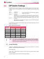
1
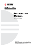
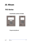
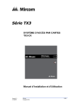
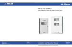
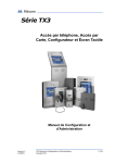
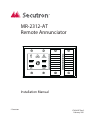
MR-2312-AT
Remote Annunciator
A.C.
ON
COMMON
TROUBLE
SIGNAL
SILENCED
BUZZER
SILENCE
SIGNAL
SILENCE
LAMP
TEST
SYSTEM
RESET
Installation Manual
© Secutron
LT-658SEC Rev.2
February 2011
Table of Contents
Table of Contents
1.0
Introduction
7
1.1
Contact Us ...................................................................................................................... 7
1.1.1
General Inquiries ............................................................................................................ 7
1.1.2
Customer Service ........................................................................................................... 7
1.1.3
Technical Support ........................................................................................................... 7
1.1.4
Website ........................................................................................................................... 7
2.0
Installation Instructions
2.1
Controls and Displays ..................................................................................................... 8
3.0
Wiring Instructions
9
4.0
DIP Switch Settings
10
4.1
Jumper Selection ............................................................................................................ 10
5.0
Specifications and Features
5.1
Enclosure ........................................................................................................................ 11
5.2
Electrical Specifications .................................................................................................. 11
5.3
Current Drain for Battery Calculations ............................................................................ 11
5.4
Environmental Specifications ......................................................................................... 11
6.0
Warranty and Warning Information
8
11
12
6.1
Warning Please Read Carefully .................................................................................... 12
6.2
Note to Installers ............................................................................................................. 12
6.3
System Failures .............................................................................................................. 12
6.3.1
Inadequate Installation ................................................................................................... 12
6.3.2
Power Failure ................................................................................................................. 12
6.3.3
Failure of Replaceable Batteries .................................................................................... 12
6.3.4
Compromise of Radio Frequency (Wireless) Devices .................................................... 13
6.3.5
System Users ................................................................................................................. 13
6.3.6
Automatic Alarm Initiating Devices ................................................................................. 13
6.3.7
Software ......................................................................................................................... 13
6.3.8
Alarm Notification Appliances ......................................................................................... 13
6.3.9
Telephone Lines ............................................................................................................. 14
6.3.10
Insufficient Time ............................................................................................................. 14
6.3.11
Component Failure ......................................................................................................... 14
6.3.12
Inadequate Testing ......................................................................................................... 14
3
Table of Contents
4
6.3.13
Security and Insurance .................................................................................................. 14
6.4
Limited Warranty ............................................................................................................ 14
6.4.1
International Warranty .................................................................................................... 14
6.4.2
Conditions to Void Warranty .......................................................................................... 15
6.5
Warranty Procedure ....................................................................................................... 15
6.6
Disclaimer of Warranties ................................................................................................ 15
6.7
Out of Warranty Repairs ................................................................................................ 15
List of Figures and Tables
List of Figures and Tables
Figure 1
Installation Diagram ........................................................................................................ 8
Table 1
Controls and Displays Listing ......................................................................................... 8
Figure 2
Wiring Diagram ............................................................................................................... 9
Table 2
Table 3
Maximum Wiring Run to Last Annunciator ..................................................................... 9
SW1 DIP Switch Settings ............................................................................................... 10
5
List of Figures and Tables
6
Introduction
1.0
Introduction
Secutron’s MR-2312-AT Annunciator is a 16-circuit annunciator for use with Secutron’s MR2300 Series Fire Alarm Control Panels. Annunciators mount into standard four-gang electrical
boxes, and may not be expanded. Control access is by a keyswitch. Each circuit indicator is a
bi-colour LED that is automatically configured to match the fire alarm control panel
configuration.
i
1.1
Note:
For ULC S527 applications the MR-2312-AT is an ancillary display device.
Contact Us
For General Inquiries, Customer Service and Technical Support you can contact us Monday to
Friday 8:00 A.M. to 5:00 P.M. E.S.T.
1.1.1 General Inquiries
Toll Free
1-888-732-8876 (North America Only)
Local
905-660-4655
Email
[email protected]
1.1.2 Customer Service
Toll Free
1-888-MIRCOM5 (North America Only)
Local
905-695-3535
Toll Free Fax
1-888-660-4113 (North America Only)
Local Fax
905-660-4113
Email
[email protected]
1.1.3 Technical Support
Toll Free
1-888-MIRCOM5 (North America Only)
888-647-2665
International
905-647-2665
Email
[email protected]
1.1.4 Website
www.secutron.com
7
Installation Instructions
2.0
Installation Instructions
Figure 1
i
Installation Diagram
Surface Mount
Flush Mount
Notes: The MR-2312-AT is supplied with NP-386 paper labels for zone identification.
This annunciator displays initiating circuit status only (no individual circuit
troubles). Indicating and relay circuits are not remotely displayed. For more
details, refer to the manual of the fire alarm control panel that the annunciator will
be connected to.
The MR-2312-AT has a keyswitch to enable the four slide-switch controls. The
key should be appropriately secured.
2.1
Controls and Displays
For precise definitions of control & display operation, refer to the manual of the fire alarm
control panel that the annunciator will be connected to.
Table 1 Controls and Displays Listing
8
Controls
Displays
System Reset, Signal Silence Switches
AC On, Common Trouble, Signal Silence LEDs
Buzzer Silence, Lamp Test Switches
16 circuit status bi-coloured (red/amber) LEDs
Wiring Instructions
3.0
Wiring Instructions
The RS-485 Wiring to the
MR-2312-AT Module is
recommended
to
be
twisted shielded pair as
shown in the diagram. The
wire gauge may be:
24 VDC
OUTPUT
-
24 VDC POWER TO
NEXT ANNUNCIATOR
+
-
24 VDC
INPUT
24 VDC POWER FROM FIRE ALARM CONTROL
PANEL OR PREVIOUS ANNUNCIATOR
+
• 22 AWG up to 2000 ft.
-
• 20 AWG up to 4000 ft.
RS-485
OUTPUT
RS-485 TO NEXT ANNUNCIATOR
(TWISTED SHIELDED PAIR)
S
The RS-485 wiring from
+
the fire alarm control panel
to the annunciator(s) must
RS-485 FROM FIRE ALARM OR PREVIOUS
ANNUNCIATOR (TWISTED SHIELDED PAIR)
be point-to-point from the
RS-485
S
INPUT
fire alarm panel to the first
annunciator, then to the
+
next annunciator, and so
on. No star wiring or TFigure 2 Wiring Diagram
tapping is allowed. Each
MR-2312-AT Annunciator
Module has a 120 ohm end-of-line resistor on its RS-485 output terminals. This is removed on
all except the last wired module.
The 24 VDC field wiring needs to be of an appropriate gauge for the number of annunciators
and the total wiring run length. Use the Current Drain for Battery Calculations on page 13 to
calculate the maximum current for all annunciators summed together.
i
Note:
!
All circuits are power limited and must use type FPL, FPLR, or FPLP power
limited cable.
Attention: Accidentally connecting any of the 24 VDC wires to the RS-485 wiring will
result in damage to the annunciator and/or to the fire alarm control panel to
which it is connected.
Table 2 Maximum Wiring Run to Last Annunciator
Total Maximum Current
for all Annunciators
18AWG
16AWG
14AWG
12AWG
Maximum Loop
Resistance
Amperes
ft.
m.
ft.
m.
ft.
m.
ft.
m.
Ohms
0.12
1180
360
1850
567
3000
915
4250
1296
15
0.30
470
143
750
229
1200
366
1900
579
6
0.60
235
71
375
114
600
183
850
259
3
0.90
156
47
250
76
400
122
570
174
2
1.20
118
36
185
56
300
91
425
129
1.5
1.50
94
29
150
46
240
73
343
105
1.2
1.70
78
24
125
38
200
61
285
87
1.0
9
DIP Switch Settings
4.0
DIP Switch Settings
Each annunciator needs to be assigned a unique, sequential address via DIP switches SW11, SW1-2, and SW1-3. DIP switch SW1-4 is used to allow disabling of some front panel slide
switches.
SW1-1
=
Address A0
SW1-2
=
Address A1
SW1-3
=
Address A2
=
When SW1-4 is “off”, the System Reset and Signal Silence slide-switches are
always disabled, regardless of the operation of the keyswitch. The Buzzer
Silence and Lamp Test slide-switches will operate with the use of the
keyswitch.
SW1-4
Three digit address of the annunciator (address
range 1 to 7 inclusive)
When SW1-4 is “on”, all four slide -switches on the front panel will operate
with the use of the keyswitch.
Set the annunciator address (see the manual for the fire alarm control panel being used), as
follows in the table below
Table 3 SW1 DIP Switch Settings
Annunciator
Address
SW1-1
SW1-2
SW1-3
1
ON
OFF
OFF
2
OFF
ON
OFF
3
ON
ON
OFF
4
OFF
OFF
ON
5
ON
OFF
ON
6
OFF
ON
ON
7
ON
ON
ON
i
4.1
SW1 DIP Switch Settings
Note:
Annunciators on a common RS-485 connection must be numbered sequentially;
i.e.: 1,2,3,4, and not randomly such as 5,3,7! Note that not all Annunciator
“Addresses” are valid for all Fire Alarm Control Panels. Refer to the Fire Alarm
Control Panel Manual for further information.
Jumper Selection
Jumper JP1 connects pins 1 and 2 and thus provides an eight bit checksum. The eight bit
checksum is used for the MR-2300 Series Panel.
JW4 (Orange Wire)
Jumper Intact = Buzzer silence & Lamp Test local function only. System Reset & Signal
Silence are disabled.
Cut Jumper (Orange Wire) to have all remote functions operate.
10
Specifications and Features
5.0
Specifications and Features
5.1
Enclosure
•
5.2
5.3
A standard 4-gang electrical box is used.
Electrical Specifications
•
24 VDC nominal voltage
•
Slide-switch controls, LED indicators, and keyswitch to enable controls.
•
Local buzzer, indicators (ac-on, common trouble, signal silence), and controls (system
reset, lamp test, buzzer silence, signal silence).
•
Annunciation of up to 16 points.
•
Not expandable.
•
Standby 35 mA Max., All LED’s illuminated 140 mA max.
Current Drain for Battery Calculations
The lamp test feature draws the maximum normal current because it illuminates all lamps on
one chassis at a time. Thus the currents are:
Normal Standby
Current = 35 mA
Maximum Current
= 140 mA
Use the “normal standby current” for battery size calculations (see the fire alarm control panel
manual for battery calculations) and includes the current drain for the Trouble Buzzer, Trouble
LED, and one alarm LED. Use the “maximum current” to calculate the wire size (see the
wiring instructions on page 10).
5.4
Environmental Specifications
This annunciator is intended for indoor use only.
11
Warranty and Warning Information
6.0
Warranty and Warning Information
6.1
i
6.2
Warning Please Read Carefully
Note to End UsersThis equipment is subject to terms and conditions of sale as follows
Note to Installers
This warning contains vital information. As the only individual in contact with system users, it is
your responsibility to bring each item in this warning to the attention of the users of this
system. Failure to properly inform system end-users of the circumstances in which the system
might fail may result in over-reliance upon the system. As a result, it is imperative that you
properly inform each customer for whom you install the system of the possible forms of failure.
6.3
System Failures
This system has been carefully designed to be as effective as possible. There are
circumstances, such as fire or other types of emergencies where it may not provide protection.
Alarm systems of any type may be compromised deliberately or may fail to operate as
expected for a variety of reasons. Some reasons for system failure include:
6.3.1 Inadequate Installation
A Fire Alarm system must be installed in accordance with all the applicable codes and
standards in order to provide adequate protection. An inspection and approval of the initial
installation, or, after any changes to the system, must be conducted by the Local Authority
Having Jurisdiction. Such inspections ensure installation has been carried out properly.
6.3.2 Power Failure
Control units, smoke detectors and many other connected devices require an adequate power
supply for proper operation. If the system or any device connected to the system operates
from batteries, it is possible for the batteries to fail. Even if the batteries have not failed, they
must be fully charged, in good condition and installed correctly. If a device operates only by
AC power, any interruption, however brief, will render that device inoperative while it does not
have power. Power interruptions of any length are often accompanied by voltage fluctuations
which may damage electronic equipment such as a fire alarm system. After a power
interruption has occurred, immediately conduct a complete system test to ensure that the
system operates as intended.
6.3.3 Failure of Replaceable Batteries
Systems with wireless transmitters have been designed to provide several years of battery life
under normal conditions. The expected battery life is a function of the device environment,
usage and type. Ambient conditions such as high humidity, high or low temperatures, or large
temperature fluctuations may reduce the expected battery life. While each transmitting device
has a low battery monitor which identifies when the batteries need to be replaced, this monitor
12
Warranty and Warning Information
may fail to operate as expected. Regular testing and maintenance will keep the system in
good operating condition.
6.3.4 Compromise of Radio Frequency (Wireless) Devices
Signals may not reach the receiver under all circumstances which could include metal objects
placed on or near the radio path or deliberate jamming or other inadvertent radio signal
interference.
6.3.5 System Users
A user may not be able to operate a panic or emergency switch possibly due to permanent or
temporary physical disability, inability to reach the device in time, or unfamiliarity with the
correct operation. It is important that all system users be trained in the correct operation of the
alarm system and that they know how to respond when the system indicates an alarm.
6.3.6 Automatic Alarm Initiating Devices
Smoke detectors, heat detectors and other alarm initiating devices that are a part of this
system may not properly detect a fire condition or signal the control panel to alert occupants of
a fire condition for a number of reasons, such as: the smoke detectors or heat detector may
have been improperly installed or positioned; smoke or heat may not be able to reach the
alarm initiating device, such as when the fire is in a chimney, walls or roofs, or on the other
side of closed doors; and, smoke and heat detectors may not detect smoke or heat from fires
on another level of the residence or building.
6.3.7 Software
Most Secutron products contain software. With respect to those products, Secutron does not
warranty that the operation of the software will be uninterrupted or error-free or that the
software will meet any other standard of performance, or that the functions or performance of
the software will meet the user’s requirements. Secutron shall not be liable for any delays,
breakdowns, interruptions, loss, destruction, alteration or other problems in the use of a
product arising our of, or caused by, the software.
Every fire is different in the amount and rate at which smoke and heat are generated. Smoke
detectors cannot sense all types of fires equally well. Smoke detectors may not provide timely
warning of fires caused by carelessness or safety hazards such as smoking in bed, violent
explosions, escaping gas, improper storage of flammable materials, overloaded electrical
circuits, children playing with matches or arson.
Even if the smoke detector or heat detector operates as intended, there may be circumstances
when there is insufficient warning to allow all occupants to escape in time to avoid injury or
death.
6.3.8 Alarm Notification Appliances
Alarm Notification Appliances such as sirens, bells, horns, or strobes may not warn people or
waken someone sleeping if there is an intervening wall or door. If notification appliances are
located on a different level of the residence or premise, then it is less likely that the occupants
will be alerted or awakened. Audible notification appliances may be interfered with by other
noise sources such as stereos, radios, televisions, air conditioners or other appliances, or
passing traffic. Audible notification appliances, however loud, may not be heard by a hearingimpaired person.
13
Warranty and Warning Information
6.3.9 Telephone Lines
If telephone lines are used to transmit alarms, they may be out of service or busy for certain
periods of time. Also the telephone lines may be compromised by such things as criminal
tampering, local construction, storms or earthquakes.
6.3.10 Insufficient Time
There may be circumstances when the system will operate as intended, yet the occupants will
not be protected from the emergency due to their inability to respond to the warnings in a
timely manner. If the system is monitored, the response may not occur in time enough to
protect the occupants or their belongings.
6.3.11 Component Failure
Although every effort has been made to make this system as reliable as possible, the system
may fail to function as intended due to the failure of a component.
6.3.12 Inadequate Testing
Most problems that would prevent an alarm system from operating as intended can be
discovered by regular testing and maintenance. The complete system should be tested as
required by national standards and the Local Authority Having Jurisdiction and immediately
after a fire, storm, earthquake, accident, or any kind of construction activity inside or outside
the premises. The testing should include all sensing devices, keypads, consoles, alarm
indicating devices and any other operational devices that are part of the system.
6.3.13 Security and Insurance
Regardless of its capabilities, an alarm system is not a substitute for property or life insurance.
An alarm system also is not a substitute for property owners, renters, or other occupants to act
prudently to prevent or minimize the harmful effects of an emergency situation.
IMPORTANT NOTE: End-users of the system must take care to ensure that the system,
batteries, telephone lines, etc. are tested and examined on a regular basis to ensure the
minimization of system failure.
6.4
Limited Warranty
Secutron Inc. together with its subsidiaries and affiliates (collectively, the “Mircom Group of
Companies”) warrants the original purchaser that for a period of three years from the date of
shipment, the product shall be free of defects in materials and workmanship under normal use.
During the warranty period, Secutron shall, at its option, repair or replace any defective
product upon return of the product to its factory, at no charge for labor and materials. Any
replacement and/or repaired parts are warranted for the remainder of the original warranty or
ninety (90) days, whichever is longer. The original owner must promptly notify Secutron in
writing that there is defect in material or workmanship, such written notice to be received in all
events prior to expiration of the warranty period.
6.4.1 International Warranty
The warranty for international customers is the same as for any customer within Canada and
the United States, with the exception that Secutron shall not be responsible for any customs
fees, taxes, or VAT that may be due.
14
Warranty and Warning Information
6.4.2 Conditions to Void Warranty
This warranty applies only to defects in parts and workmanship relating to normal use. It does
not cover:
6.5
•
damage incurred in shipping or handling;
•
damage caused by disaster such as fire, flood, wind, earthquake or lightning;
•
damage due to causes beyond the control of Secutron such as excessive voltage,
mechanical shock or water damage;
•
damage caused by unauthorized attachment, alterations, modifications or foreign
objects;
•
damage caused by peripherals (unless such peripherals were supplied by Secutron);
•
defects caused by failure to provide a suitable installation environment for the products;
•
damage caused by use of the products for purposes other than those for which it was
designed;
•
damage from improper maintenance;
•
damage arising out of any other abuse, mishandling or improper application of the
products.
Warranty Procedure
To obtain service under this warranty, please return the item(s) in question to the point of
purchase. All authorized distributors and dealers have a warranty program. Anyone returning
goods to Secutron must first obtain an authorization number. Secutron will not accept any
shipment whatsoever for which prior authorization has not been obtained. NOTE: Unless
specific pre-authorization in writing is obtained from Secutron management, no credits will be
issued for custom fabricated products or parts or for complete fire alarm system. Secutron will
at its sole option, repair or replace parts under warranty. Advance replacements for such items
must be purchased.
Note: Secutron’s liability for failure to repair the product under this warranty after a reasonable
number of attempts will be limited to a replacement of the product, as the exclusive remedy for
breach of warranty.
6.6
Disclaimer of Warranties
This warranty contains the entire warranty and shall be in lieu of any and all other warranties,
whether expressed or implied (including all implied warranties of merchantability or fitness for
a particular purpose) And of all other obligations or liabilities on the part of Secutron neither
assumes nor authorizes any other person purporting to act on its behalf to modify or to change
this warranty, nor to assume for it any other warranty or liability concerning this product.
This disclaimer of warranties and limited warranty are governed by the laws of the province of
Ontario, Canada.
6.7
Out of Warranty Repairs
Secutron will at its option repair or replace out-of-warranty products which are returned to its
factory according to the following conditions. Anyone returning goods to Secutron must first
15
Warranty and Warning Information
obtain an authorization number. Secutron will not accept any shipment whatsoever for which
prior authorization has not been obtained.
Products which Secutron determines to be repairable will be repaired and returned. A set fee
which Secutron has predetermined and which may be revised from time to time, will be
charged for each unit repaired.
Products which Secutron determines not to be repairable will be replaced by the nearest
equivalent product available at that time. The current market price of the replacement product
will be charged for each replacement unit.
The preceding information is accurate as of the date of publishing and is subject to change or revision
without prior notice at the sole discretion of the Company.
WARNING: Secutron recommends that the entire system be completely tested on a regular basis.
However, despite frequent testing, and due to, but not limited to, criminal tampering or electrical
disruption, it is possible for this product to fail to perform as expected.
NOTE: Under no circumstances shall Secutron be liable for any special, incidental, or
consequential damages based upon breach of warranty, breach of contract, negligence, strict
liability, or any other legal theory. Such damages include, but are not limited to, loss of profits,
loss of the product or any associated equipment, cost of capital, cost of substitute or replacement
equipment, facilities or services, down time, purchaser’s time, the claims of third parties,
including customers, and injury to property.
SECUTRON MAKES NO WARRANTY OF MERCHANTABILITY OR FITNESS FOR A PARTICULAR
PURPOSE WITH RESPECT TO ITS GOODS DELIVERED, NOR IS THERE ANY OTHER WARRANTY,
EXPRESSED OR IMPLIED, EXCEPT FOR THE WARRANTY CONTAINED HEREIN.
16
© 2011 Secutron Inc.
No part of this publication may be reproduced, transmitted,
transcribed, stored in a retrieval system, or translated into
any language or computer language, in any form by any
means electronic, magnetic, optical, chemical, manual, or
otherwise without the prior consent of Secutron.
Canada
25 Interchange Way
Vaughan, ON L4K 5W3
Tel:
(888) SECUTRON
(888) 732-8876
Fax:
(905) 660-4113
U.S.A
4575 Witmer Industrial Estates
Niagara Falls, New York 14305
Tel:
(888) SECUTRON
(888) 732-8876
Fax:
(905) 660-4113
Technical Support
North America Only
Tel:
(888) Mircom5
(888) 647-2665
International
Tel:
(905) 647-2665