1
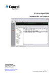
UCIT Series User’s Manual UCIT Series Mobile DVR User’s Manual 4-Channel Industry-Grade HD Mobile DVR Integrating 3G, Wi-Fi, GPS and Voice Conversation V2.2 1 UCIT Series User’s Manual Contents 1. Product Introduction ......................................................................................................................4 1.1. Overview .............................................................................................................................5 1.2. Specifications ......................................................................................................................5 1.2.1. Specifications ............................................................................................................5 1.3. Requirments ........................................................................................................................6 2. Appearance and Accessories........................................................................................................7 2.1. Front Panel Definitions ........................................................................................................8 2.1.1. LED Indicator ............................................................................................................8 2.1.2. Other Definitions .......................................................................................................8 2.2. Rear Panel Definitions ........................................................................................................9 2.3. Definitions of External Cables .............................................................................................9 2.3.1. Power Cable .............................................................................................................9 2.3.2. Audio/Video Input/output Cables ............................................................................10 2.3.3. GPS Module............................................................................................................10 2.3.4. 3G, Wi-Fi Antenna ..................................................................................................10 2.3.5. Extension Cables .................................................................................................... 11 2.4. Infrared Remote Controller ...............................................................................................12 3. Storage Media Installation and Replacement ............................ Error! Bookmark not defined.3 3.1. Hard drive Installation .....................................................................................................133 3.2 SD Card Installation ...........................................................................................................14 3.3. Antenna Installation ..........................................................................................................15 4. OSD Menu Overview...................................................................................................................16 4.1. Menu Structure..................................................................................................................16 4.2. User Login .........................................................................................................................17 4.3. Main Menu ........................................................................................................................17 4.4. Video Playback .................................................................................................................18 4.5. System Setup ....................................................................................................................19 4.5.1. Basic Setup .............................................................................................................19 4.5.2. Recording Setup .....................................................................................................20 4.5.3. Startup/Shutdown Setup.........................................................................................20 4.5.4. Alarm Setup ............................................................................................................21 4.5.5. Security Setup ........................................................................................................24 4.5.6. Network Setup ........................................................................................................24 4.6. System Information ...........................................................................................................26 4.7. Management Tools ............................................................................................................26 4.7.1. Log Management ....................................................................................................27 4.7.2. Disk Management ...................................................................................................27 4.7.3. Factory Settings ......................................................................................................29 4.7.4. Configuration Management ....................................................................................29 4.7.5. PTZ Management ...................................................................................................30 4.7.6. OSD Setup ......................................................................................................... ….30 4.7.7. System Upgrading ..................................................................................................31 2 UCIT Series User’s Manual 4.7.8. Serial Ports Management .......................................................................................31 4.8. Shortcuts Keys ..................................................................................................................32 4.8.1. F1 Status Menu ......................................................................................................32 4.8.2. F2 Status Menu (No status menu is shown by pressing F2) .................................32 3 UCIT Series User’s Manual 1. Product Introduction 1.1. Overview UCIT series is a high-end Mobile DVR (MDVR) dedicated for mobile surveillance of your fleet, applying high-speed processor and embedded operating system integrating various state-ofthe-art technologies. Features include audio/video codec technologies, large-capacity hard drive storage technologies, streaming media network technologies. Product picture: 4 UCIT Series User’s Manual 1.2. UCIT Technical Overview 1.2.1. Specifications Item Description OS Linux Graphical User Interface (GUI) System parameters can be modified through an external display and included remote controller Security Management Two Level management for user password, administrator password, supporting encrypted transmission Video Audio Recording Alarm Input/Output 4-channel video input, 1channel video output; 1.0Vp-p, 75Ω OSD Character superposition function, information superposition of time and date, device ID and GPS, etc. Video Compression Format H.264 Dual-Stream Supported (3G and WiFi) Frame Rate PAL: 100 frames/s, up to 25 frames/s per channel; NTSC: 120 frames/s, up to 30 frames/s per channel Resolution CIF, HD1 and D1 for selection, supporting 2 channels of D1+ 2 channels of CIF at the most Bit Rate CIF: 256Kbps ~ 1.5 Mbps, 8-level bit rates for selection HD1: 600Kbps ~ 2 Mbps, 8-level bit rates for selection D1: 800Kbps ~ 3Mbps, 8-level bit rates for selection Input/Output 4 Channel input, 1 Channel output Compression Format G.726 codec Storage Medium Supports one 2.5” hard drive (up to 1TB) and one SD card (up to 32GB) for data redundancy storage technology; File Format ASF/FAT32 Video Strategies System Startup (default), timed recording, recording triggered by alarm and event, manual recording Video Search Searching by time, type, storage device and other conditions Video Playback Playback on local device using connected external monitor Alarm Output All general playback functions Input/ Alarm Recording 6-channel on/off signal alarm input, 1-channel on/off signal alarm output Prerecording function 15 seconds before alarm, duration of recording after alarm can be adjusted from 30s ~ 30min Communication Ports RS232, RJ45 10M/100M self-adaptable network interface Wireless Transmission Embedded 3G wireless transmission module, WCDMA, CDMA2000, GPRS, EDGE Embedded Wi-Fi module; GPS Supporting external GPS 5 UCIT Series User’s Manual PTZ Control Supporting PTZ control realized by local ad client software; Parameter Configuration Supporting parameter configuration functions for mobile DVR coding channel; G-Sensor Embedded Accelerometer Power Operating Environment Input Voltage 8VDC - 36VDC Output Voltage +12V@4*0.5A; [email protected] Power Consumption <10W in normal operation; <0.5W in standby mode Temperature Normal Operating Temperature: 0-60 degrees Centigrade Humidity 10% to 95% Relative Humidity Dimensions 160(W) x62(H) x200(D) mm. Weight Net: 2200g, Gross: 3500g 1.3. Installation 1.3.1. Requirements To ensure operator safety, device stability and extended service life, please follow the below guidelines when installing and operating the device: 1) 2) 3) Power supply and grounding: a) The direct input range of the power supply of the device is from 8VDC to 36VDC. b) The device has internal capacitors that store power. Please disconnect all power and wait 5 minutes before connecting any cameras, alarm inputs, or external monitors. c) Do not connect any other device in series with the UCIT. d) For Alarm Input Signals, 2VDC or less is a low input and 5VDC-30VDC is high input. 2.1VDC-4.9VDC are not supported. e) Ensure ground on power harness is directly connected to chassis ground. Humidity requirements: a) The device should be installed in dry environment avoiding moisture. Do not install the device in locations with the possibility of water accumulation. Installation locations: a) Physical location of installation should be in a secure location with the least amount of vibration possible. b) All power, camera, and alarm harness cables should be ran and protected to prevent chafing, short-circuits, or other damage. c) Avoid direct sunlight exposure. d) Unit is to be installed either vertically or horizontally. 6 UCIT Series User’s Manual 2. Product Appearance Front View: Back View: 7 UCIT Series User’s Manual 2.1. Front Panel Definitions 2.1.1. LED Indicator [PWR]Power Indicator Solid: Unit is powered on [ALM]Alarm indicator. Flashing: Unit is recording an active alarm [REC]Recording indicator: Flashing: Unit is recording [HD]Hard drive indicator: Solid: HDD has been successfully detected and loaded Not Illuminated: HDD has not been detected or has failed Flashing: HDD is recording [SD]SD card indicator: Solid: SD card has been successfully detected and loaded Not Illuminated: SD card has not been detected or has failed Flashing: SD card is recording [GPS]GPS signal indicator. Solid: GPS lock has been obtained [ERR]Error indicator. If illuminated, contact Safety Track Support [V-Loss]Video loss indicator: Flashing: One or more cameras are not detected [HTR]Heating indicator. Flashing: Optional HDD heater is running [NET]Network indicator. Solid: Network is connected to back-end server 2.1.2. Other Definitions [IR]IR receiver for remote controller. [LOCK]Hard drive security lock. Note: The device can only be powered on once HDD sled is locked into position. If unit is not locked, the unit will shut off on power-up. [MIC]MIC input. [EAR]External Speaker output. 8 UCIT Series User’s Manual 2.2. Rear Panel Definitions ● ● ● ● ● ● ● ● [PWR]Power Supply Harness. [GPS]GPS Antenna Harness. [EXTEND I/O]Alarm Input/Output Harness. [RJ45]Network interface. [AV IN]Audio/video input interface. [AV OUT]Audio/video output interface. [WI-FI]WiFi Antenna Connection. [3G]3G Antenna Connection. 2.3. Cable Harnesses 2.3.1. Power Cable Power Harness Wire Color Connection Description Black BAT- Ground Red BAT+ Positive 8VDC-36VDC Constant Yellow ACC Positive 8VDC-36VDC Switched 9 UCIT Series User’s Manual 2.3.2. Audio/Video Input/Output Cables Left Right Left: Audio/Video Input/Output Cable Right: Tie line. Interface Name Description Video Input VID1-VID4 Camera Input Audio/video output AVOUT Audio/Video output 2.3.3. GPS Module GPS module antenna 2.3.4. 3G, Wi-Fi Antenna 3G antenna Wi-Fi antenna 10 UCIT Series User’s Manual 2.3.5. Extension Cables Extension cables Cable Color Label White White White White Black Grey Red Yellow Black Grey Red Yellow Orange Pink Black Purple Brown White White White Black Yellow Black Red Diagram of Extension Cables 11 UCIT Series User’s Manual 2.4. Infrared Remote Controller Key Function Image Remote on. [LOGIN] Login to On Screen Display (OSD) [0-9] [0-9] keys: In the setting menus, the numeric keys are used for numerical input. During video playback, numbers 1-4 are used for switching between single windows of channels 1-4, number 5 is used for switching to synchronous playback of all 4 channels. [-][+] Cursor Scrolling; Setting Selction [DEL] Delete [EXIT] Exits to the previous menu or returns to the main menu. [ENTER] Confirms parameter selection and settings as well as operations like play. ▲, , , Arrow keys that move the cursor upward, downward, leftward and rightward. The left and right keys are used for increasing and decreasing the volume during surveillance playback. [GOTO] Plays the video from the selected time. [INFO] Displays system information in the surveillance status. Rewind Play Fast Forward Starts recording in manual recording mode. Stops recording in manual recording mode. Stops playing the video in playback mode. Pauses during playback. [F1] Displays information like acceleration GPS, Wi-Fi, 3G module, SIM card, dialing, online, etc. in the surveillance menu. This function is used for UCITB. [F2] Monitors single channel and displays PTZ information. [F3] Reserved for future use 12 UCIT Series User’s Manual 3. Storage Media Installation and Replacement 3.1. Hard Drive Installation Step 1. Unlock the hard drive and remove the hard drive sled. Step 2. Remove the bolts (7 in total) as outlined below Remove 1 bolt on the back side of the enclosure Step 3. Install the shock pads Install the shock pads on both sides as outlined below. 13 UCIT Series User’s Manual Step 4. Install the rubber shock absorbing covers Mount the rubber shock absorbing covers on both sides of the SATA hard drive, with the side of the cover with the lug close to the PCB. Step 5. Close the enclosure and fasten the screws 3.2. SD Card Installation Open the hard drive lock with the key and remove the hard drive sled, then remove the 4 screws holding the SIM card cover. The SD card slot is shown in the figure below. Since the SD card slot is close to the 3G module, to facilitate inserting and removing the SD card, it is recommended to remove the 3G module before inserting or removing the SD card. Press the card and pull out the 3G module 14 UCIT Series User’s Manual Remove the 3G module Insert the SD card 3.3. Antenna Installation Connections for Wi-Fi and 3G antennas are equipped on the back panel of the device. For connection of corresponding antennas, please refer to the figure below: Wi-Fi antenna 3G antenna connection 15 UCIT Series User’s Manual 4. OSD Menu Overview 4.1. Menu Tree All videos Video playback Alarm video Basic settings Recording settings System settings On/off settings Alarm settings Security management Login Network settings System information Log management Disk management Factory settings Configuration management Management tools PTZ management Display settings System upgrading Serial port management Menu Structure 16 UCIT Series User’s Manual 4.2. User Login Press Login on the remote, and enter password if configured (default admin password is 888888) LOGIN DEV ICE NO.:00000 USER NAME : user / admi n PASSWORD : ****** LOGIN CANCEL 4.3. Main Menu After login, you will be at the main menu consisting of: PLAYBACK, SYSTEM SET, SYSTEM INFO, MANAGE TOOL. 17 UCIT Series User’s Manual 4.4. Video Playback In the main menu, press the arrow keys to select the video to playback, and press [ENTER] to enter the REC SEARCH interface. REC SEARCH 01 02 03 04 05 06 07 08 09 10 11 12 13 14 15 16 17 18 19 20 21 22 23 24 25 26 27 28 29 30 31 REC TYPE:ALL/ALARM DISK SELECT:HDD/SD DATE:2011-05-27 START TIME:00:00 END TIME:23:59 SEARCH REC TYPE: Press [Enter] to select types to recall: All videos\Alarm video (default is all videos) DISK SELECT: Press [Enter] to select disk: SD\HDD. (default is HDD) DATE: Press the number keys to input the date. (default is current date) START TIME: Press the number keys to input the time. (current is 00:00) END TIME: Press the number keys to input the time. (default is 23:59) SEARCH: Move the cursor to “search” and press [Enter]. SEARCH RESULT DATE: 2011-05-27 TYPE Normal Normal Normal Normal Alarm Alarm Alarm Alarm FIRST RES START END CH SIZE D1 D1 CIF CIF D1 D1 CIF CIF 15:30 15:30 15:30 15:30 16:10 16:10 16:10 16:10 16:00 16:00 16:00 16:00 16:12 16:12 16:12 16:12 1 2 3 4 1 2 3 4 154M 53M 100M 98M 7M 7M 9M 10M UP DOWN LAST Press the arrow keys to select the video to be reviewed then press [ENTER] to play the video. Press [EXIT] to return to the previous menu. Use arrow keys to move from pages of results of the search. 18 UCIT Series User’s Manual 4.5. System Setup In the main menu, press the arrow keys to select the SYSTEM SETUP menu, and press [ENTER] to enter the following SYSTEM SETUP menu. The setup menu consists of the following submenus: BASE SET, REC SET, POWER SET, ALARM SET, SECURITY, NETWORK. SYSTEM SETUP 4.5.1. Basic Setup This menu configures the identification parameters of the device. BASIC SETUP DATE TYPE:YMD/DMY/MDY TIMEZONE:GMT +08(00~+12 / -01~-12 ) DATE:2011-05-27 09:01:30 IDLE TIME:30(30~3600s) DEVICE NO. :11111 COMPANY NAME:Company Name VEHICLE NO.:00000 DRIVER NAME:Driver Name BUS LINE NO.:Bus line no. SAVE Note: Do not modify the ‘DEVICE NO.’ field without first contacting Safety Track Support. 19 UCIT Series User’s Manual 4.5.2. Record Setup This menu is for settings of recording parameters. Do not modify these settings without first contacting Safety Track Support. RECORD SETUP SYSTEM:PAL/NTSC RECORD MODE:AUTO/TIMED/ ALAR M/MANU AL RESOLUTION:D1/HD1/CIF BITRATE: D1(2048 /2000 /1600 /1400 /1200 /1000 / 800 /600)HD1(1500 /1300 /1100 /900 /800 /700 /600 /500)CIF(1200 /1000 /800 /700/ 600/ 500/ 400 /300) AUDIO :ON/OFF TIME SLICE:15/30/45/60 (M) OVERWRITE: NORMAL/NONE/ALL SD FUNCTION: NO REC/MIRR REC/ LOST REC CHANNEL QUALITY CH1(1~4) 1(1~5) TIME LIST ALARM DELAY: 30(30~1800S) FRAME RATE 25(1~30) SUB-STREAM RECORD ON/OFF SAVE 4.5.3. Power Setup Set on/off parameters. POWER SETUP POWER MODE: DELAY POWER OFF: DELAY TIME: POWER ON TIME: POWER OFF TIME: ACC / TIME ON/OFF 5(3~240)(M) HH:MM:SS HH:MM:SS SAVE 20 UCIT Series User’s Manual On/off mode Always set to ACC mode. Delayed off This setting configures a delayed shutdown when switch power is lost. Delay time The delay time can be set between 5 and 240 minutes Timed on time Not Applicable Timed off time Not Applicable 2 4.5.4. Alarm Setup Set output parameters upon alarm. ALARM SETUP ENABLE PWL RECORD FUNCTION I /01 ON HIGH ON LEFT/RIGHT I /02 ON HIGH OFF MIDDLE I /03 ON LOW ON BRAKE I /04 OFF LOW OFF FRONT I /05 OFF HIGH ON POSTERN I /06 OFF LOW ENABLE OFF PWL OFF HIGH INPUT OUTPUT RELAY OUTPUT SAVE SPEED G-SENSOR BACKING MOVE DETECT Alarm input Supports synchronous input of up to 6 channels of alarm. “Enable”: Sets whether to enable the input of that particular channel. “PWL”: Sets High/Low level input. “Record”: Sets recording options for alarm triggers. 21 UCIT Series User’s Manual GPS Overspeed GPS OVER SPEED THRESHOLD:60(0~999)(km/h) ENABLE:ON/OFF SAVE Threshold: 60km/h by default, adjustable within the range of 0~999. Press DEL to delete the original number and use numbers to enter new setting. Note: Only KM/H is supported at this time. For MPH, use calculator to translate to KM/H. Enable: On/Off, press [ENTER] to input; On: When the speed of the GPS exceeds the threshold value, the alarm recording will be started and alarm logs will be recorded; Off: When the speed of the GPS exceeds the threshold value, neither the alarm recording nor the alarm logs will be started Upon completion, press the Save button to save settings. Acceleration/Impacts/Hard Braking Move the cursor to “G-Sensor”, press [ENTER] to enter the following menu of G-Sensor settings: G-SENSOR ALARM SWITCH: ON/OFF THRESHOLD VALUES X: 2.00 g Y: 2.00 g Z: 2.00 g STATUS: X= -0.12 ADJUST Y= -0.03 Z= -0.01 SAVE 22 UCIT Series User’s Manual “Threshold”: Set values of X, Y and Z directions within the range of 0.00g--9.99g, press DEL to delete the original number and use numbers to enter new setting. A good baseline for settings is 3.00g for each axis. “Alarm Switch”: set whether to enable or disable G-sensor alarm, press [ENTER] to input. Alarm on: In the recording status, when any of the directions of X, Y and Z exceed the “Threshold”, the alarm recording and the alarm logs will be started. Alarm off: In the recording status, when any of the directions of X, Y and Z exceed the “Threshold”, neither the alarm recording nor the alarm logs will be started. “Adjust”: This calibrates the accelerometer. Use this option when the vehicle is not moving. Upon completion, press the Save button to save settings. Motion Detection This option is not supported at this time. MOTION DETECTION CHA NNE L LEVEL ENABLE AREA CHI/ CH2/CH3/ CH4 HIGH/MID/ LOW OFF/ON SETUP SAVE 23 UCIT Series User’s Manual 4.5.5. Security Setup Set login passwords SECURITY PASSWORD: ON/OFF USER PWD: ****** CONFIRM: ****** INPUT NOT SAME! ADMIN PWD: ****** CONFIRM : ****** SAVE NOTICE:PASSWORD IS 6 NUMBE RS! Password Set whether to enable the login password, and then press [ENTER] to input. On: When log in with the Admin password, Admin\User password can be set; When log in with the user password, only the User password can be set, press numeric keys to input, the passwords inputted twice should be consistent. Off: Password cannot be set. After entering the menu, one can directly enter the main menu without login. Note: If there are multiple devices with the same power supply for recording, please set different password and device ID for each device so as to avoid disturbing other devices when operating one of them, the device ID may be modified in Basic Setup. 4.5.6. Network Setup NETWORK SETUP LOCA L SETUP IP ADDRESS: 192. 168. 000. 192 NE TMASK: 255. 255. 255. 000 GATE WAY: 192. 168. 000. 001 MAC: 00.44.53.75.55.56 CENTE R SETUP TYPE: IP/DOMA IN DOMA IN: www.123.cn 3G SERVER :192 . 168 . 001 . 000 PORT:5678 WIFI SERVE R :192 . 168 . 001 . 000 PORT:5678 SAVE 3G DDNS WIFI 24 UCIT Series User’s Manual Local setup This setting should not be modified, as it is only used for LAN connections Center setup This setting tells the unit how to talk back to the back-end to facilitate streaming and should not be modified except under the direction of Safety Track Support. 3G Setup This setting tells the unit how to talk back to the back-end to facilitate streaming and should not be modified except under the direction of Safety Track Support. 3G SETUP 3G FN:ON / OFF TYPE:WCDMA / EVDO / TD TRIGGER NO.1: LINK MODE:NORMAL/ TRIGGER NO.2: TRIGGER CALL NO.1: VOICE FN: OFF/ON CALL NO.2: CENTER NO.: *99# / #777 / *99***1# APN: 3gnet / ctnet / cmnet USER NAME: card PASSWORD: **** SAVE Wi-Fi Setup For Non-3G models, this will be set by Safety Track prior to shipment and should not be modified. WIFI SETUP WIFI: ON / OFF ENCRYPT: ON / OFF ENCRYPT TYPE: WEP IP: 192.168.000.192 GATEWAY: 192.168.000.001 SUB-MASK: 255.255.255.000 SSID: WIFI PASSWORD: SAVE 25 UCIT Series User’s Manual 4.6. System Info This menu shows vital information of the device and should only be accessed for troubleshooting purposes. SYSTEM INFO FIRMWARE VER:V000001 HARDWARE VER:V0001 MCU VER:V000002 DEVICE SN:V000002 CAPACITY MEDIUM SD HDD TOTAL 7.3893GB REMAINING 486.0156MB 298.0530GB 724.5000MB 4.7. Management Tools In the main menu, press the arrow keys to select Management Tools menu and press [ENTER] to enter the following menu. The Management Tools menu consists of Log Management, Disk Management, Default settings, Configuration Management, PTZ Management, OSD Settings, System Upgrade and Serial Port Management. MANAGE TOOL LOG MANAGE DISK MANAGE DEFAULT SET CFG MANAGE PTZ MANAGE OSD SET SYS UPGRADE SERIALMANAGE 26 UCIT Series User’s Manual 4.7.1. Log Management The Log Management records events of startup and shutdown, GPS time correction, alarm moment, etc., including date, time and event name. LOG MANAGE START TIME:2011-05-27 00:00:00 END TIME:2011-05-27 23:59:59 DATE TIME SEARCH EVENT NAME 11/05/27 15:30:25 alarm in 1 11/05/27 16:10:37 alarm in 2 11/05/27 17:00:35 power on 11/05/27 17:30:56 alarm in FIRST UP DOWN 4 LAST 4.7.2. Disk Management Used to format HDD or SD Card DISK MANAGE DISK FORMAT DISK SELECT CANCEL SD/HDD FORMAT The data will lost against ‘FORMAT’, otherwise,please press ‘CANCEL’。 Disk Selection Select SD or HDD, press [ENTER] for selection. Format Button Select the Format Button and press [ENTER], the following window will pop up. 27 UCIT Series User’s Manual Message Warning: Format SD card ? Yes No Message Warning: Format hard disk ? Yes No “Yes”: Start formatting the SD card or hard drive, press [ENTER] to input. “No”: Cancel formatting and return to the Management Tools menu. 28 UCIT Series User’s Manual 4.7.3. Factory Settings This restores factory settings of the device, and the settings of the system will restore the default settings. Message Warning: Default all settings? Yes No “Yes”: Restore factory settings. “No”: Return to the Management Tools menu. 4.7.4. Configuration Management Imports and exports configuration files. CONFIG MANAGE IMPORT CONFIG FILE: SD/HDD IMPORT CFG EXPORT CURRENT CONFIG FILE: SD/HDD EXPORT CFG 29 UCIT Series User’s Manual 4.7.5. PTZ Management Not Used PTZ MANAGE CHANNEL:CH1 CH2 CH3 CH4 ADDRESS:1(0~255) 1(0~255) 1(0~255) 1(0~255) BAUDRATE:4 CHANNEL(600/1200/2400/4800/9600/ 19200/38400/57600/115200) PROTOCOL:4 CHANNEL ( Pelco_D/Pelco_P ) SAVE 4.7.6. OSD Setup OSD SETUP REAL TIME DISPLAY TIME: YES/NO RECORD OVERLAY DISPLAY TIME: YES/NO VEHICLE NO: YES/NO GPS: YES/NO SAVE 30 UCIT Series User’s Manual 4.7.7. System Upgrade SYSTEM UPGRADE CURRENT VER: T070801/T123000/V42201/V051011 UPGRADE TYPE: Uboot / Kernel / Rootfs / App /ALL UPGRADE FROM: SD /HDD UPGRADE 4.7.8. Serial Management Not Used SERIAL MANAGE CHOICES SERIAL 1 PTZ / LED SCREEN / External G SERIAL 2 PTZ / LED SCREEN / External G SAVE 31 UCIT Series User’s Manual 4.8. Shortcuts Keys 4.8.1. F1 Status Menu Press F1 with the remote controller, the video output display of the device will include the below parameters: Acceleration: X= -0.22g, Y= 0.31g, Z= -0.94g GPS module: No/Yes Longitude: 0/113°56. 4695 'E Latitude: 0/22°33. 3895 'N Speed: 0 KM/H Satellites detected: 0/12 Altitude: 0/46M 3G module: No/Yes Wi-Fi module: No/Yes SIM: No/Yes Wi-Fi signal: 0 (55/97) Signal: 0/31 Wi-Fi online: FAIL/SUCCESSFUL Dial: FAIL /Successful Online: No/Yes 4.8.2. F2 and F3 Status Menu Reserved for Future Use 32