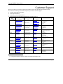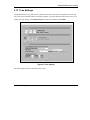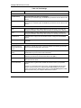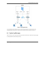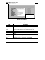
1
Vantage RADIUS 50
User’s Guide
Version 1.0
August 2004
Vantage RADIUS User’s Guide
Copyright
Copyright © 2003 by ZyXEL Communications Corporation.
The contents of this publication may not be reproduced in any part or as a whole, transcribed, stored in a
retrieval system, translated into any language, or transmitted in any form or by any means, electronic,
mechanical, magnetic, optical, chemical, photocopying, manual, or otherwise, without the prior written
permission of ZyXEL Communications Corporation.
Published by ZyXEL Communications Corporation. All rights reserved.
Disclaimer
ZyXEL does not assume any liability arising out of the application or use of any products, or software
described herein. Neither does it convey any license under its patent rights nor the patent rights of others.
ZyXEL further reserves the right to make changes in any products described herein without notice.
This publication is subject to change without notice.
Trademarks
Trademarks mentioned in this publication are used for identification purposes only and may be properties of
their respective owners.
ii
Copyright
Vantage RADIUS User’s Guide
Federal Communications Commission (FCC)
Interference Statement
This device complies with Part 15 of FCC rules. Operation is subject to the following two conditions:
This device may not cause harmful interference.
This device must accept any interference received, including interference that may cause undesired
operations.
This equipment has been tested and found to comply with the limits for a CLASS B digital device pursuant to
Part 15 of the FCC Rules. These limits are designed to provide reasonable protection against harmful
interference in a commercial environment. This equipment generates, uses, and can radiate radio frequency
energy, and if not installed and used in accordance with the instructions, may cause harmful interference to
radio communications.
If this equipment does cause harmful interference to radio/television reception, which can be determined by
turning the equipment off and on, the user is encouraged to try to correct the interference by one or more of
the following measures:
Reorient or relocate the receiving antenna.
Increase the separation between the equipment and the receiver.
Connect the equipment into an outlet on a circuit different from that to which the receiver is connected.
Consult the dealer or an experienced radio/TV technician for help.
Notice 1
Changes or modifications not expressly approved by the party responsible for compliance could void the
user's authority to operate the equipment.
Certifications
1.
2.
3.
Go to www.zyxel.com
Select your product from the drop-down list box on the ZyXEL home page to go to that product's page.
Select the certification you wish to view from this page
FCC
iii
Vantage RADIUS User’s Guide
Information for Canadian Users
The Industry Canada label identifies certified equipment. This certification means that the equipment meets
certain telecommunications network protective, operation, and safety requirements. The Industry Canada
does not guarantee that the equipment will operate to a user's satisfaction.
Before installing this equipment, users should ensure that it is permissible to be connected to the facilities of
the local telecommunications company. The equipment must also be installed using an acceptable method of
connection. In some cases, the company's inside wiring associated with a single line individual service may
be extended by means of a certified connector assembly. The customer should be aware that the compliance
with the above conditions may not prevent degradation of service in some situations.
Repairs to certified equipment should be made by an authorized Canadian maintenance facility designated by
the supplier. Any repairs or alterations made by the user to this equipment, or equipment malfunctions, may
give the telecommunications company cause to request the user to disconnect the equipment.
For their own protection, users should ensure that the electrical ground connections of the power utility,
telephone lines, and internal metallic water pipe system, if present, are connected together. This precaution
may be particularly important in rural areas.
Caution
Users should not attempt to make such connections themselves, but should contact the appropriate electrical
inspection authority, or electrician, as appropriate.
Note
This digital apparatus does not exceed the class A limits for radio noise emissions from digital apparatus set
out in the radio interference regulations of Industry Canada.
iv
Information for Canadian Users
Vantage RADIUS User’s Guide
ZyXEL Limited Warranty
ZyXEL warrants to the original end user (purchaser) that this product is free from any defects in materials or
workmanship for a period of up to two years from the date of purchase. During the warranty period, and upon
proof of purchase, should the product have indications of failure due to faulty workmanship and/or materials,
ZyXEL will, at its discretion, repair or replace the defective products or components without charge for
either parts or labor, and to whatever extent it shall deem necessary to restore the product or components to
proper operating condition. Any replacement will consist of a new or re-manufactured functionally
equivalent product of equal value, and will be solely at the discretion of ZyXEL. This warranty shall not
apply if the product is modified, misused, tampered with, damaged by an act of God, or subjected to
abnormal working conditions.
NOTE
Repair or replacement, as provided under this warranty, is the exclusive remedy of the purchaser. This
warranty is in lieu of all other warranties, express or implied, including any implied warranty of
merchantability or fitness for a particular use or purpose. ZyXEL shall in no event be held liable for indirect
or consequential damages of any kind of character to the purchaser.
To obtain the services of this warranty, contact ZyXEL's Service Center for your Return Material
Authorization number (RMA). Products must be returned Postage Prepaid. It is recommended that the unit be
insured when shipped. Any returned products without proof of purchase or those with an out-dated warranty
will be repaired or replaced (at the discretion of ZyXEL) and the customer will be billed for parts and labor.
All repaired or replaced products will be shipped by ZyXEL to the corresponding return address, Postage
Paid. This warranty gives you specific legal rights, and you may also have other rights that vary from country
to country.
Online Registration
Register online registration at www.zyxel.com for free future product updates and information.
ZyXEL Limited Warranty
v
Vantage RADIUS User’s Guide
Customer Support
When you contact your customer support representative please have the following information ready:
Please have the following information ready when you contact customer support.
• Product model and serial number.
• Warranty Information.
• Date that you received your device.
• Brief description of the problem and the steps you took to solve it.
METHOD
LOCATION
WORLDWIDE
SUPPORT E-MAIL
SALES E-MAIL
[email protected]
TELEPHONE1
1
FAX
+886-3-578-3942
WEB SITE
FTP SITE
www.zyxel.com
www.europe.zyxel.com
[email protected]
+886-3-578-2439
[email protected]
+1-800-255-4101
ftp.zyxel.com
ftp.europe.zyxel.com
NORTH AMERICA
www.us.zyxel.com
+1-714-632-0882
GERMANY
FRANCE
DENMARK
NORWAY
SWEDEN
FINLAND
1
ZyXEL Communications Corp.
6 Innovation Road II
Science Park
Hsinchu 300
Taiwan
ZyXEL Communications Inc.
1130 N. Miller St.
Anaheim
CA 92806-2001
U.S.A.
[email protected]
+1-714-632-0858
ftp.us.zyxel.com
[email protected]
+49-2405-6909-0
www.zyxel.de
[email protected]
+49-2405-6909-99
ZyXEL Deutschland GmbH.
Adenauerstr. 20/A2 D-52146
Wuerselen
Germany
[email protected]
+33 (0)4 72 52 97 97
www.zyxel.fr
ZyXEL France
1 rue des Vergers
Bat. 1 / C
69760 Limonest
France
www.zyxel.es
ZyXEL Communications
Alejandro Villegas 33
1º, 28043 Madrid
Spain
www.zyxel.dk
ZyXEL Communications A/S
Columbusvej 5
2860 Soeborg
Denmark
www.zyxel.no
ZyXEL Communications A/S
Nils Hansens vei 13
0667 Oslo
Norway
www.zyxel.se
ZyXEL Communications A/S
Sjöporten 4, 41764 Göteborg Sweden
www.zyxel.fi
ZyXEL Communications Oy
Malminkaari 10
00700 Helsinki
Finland
+33 (0)4 72 52 19 20
SPAIN
REGULAR MAIL
[email protected]
+34 902 195 420
[email protected]
+34 913 005 345
[email protected]
+45 39 55 07 00
[email protected]
+45 39 55 07 07
[email protected]
+47 22 80 61 80
[email protected]
+47 22 80 61 81
[email protected]
+46 31 744 7700
[email protected]
+46 31 744 7701
[email protected]
+358-9-4780-8411
[email protected]
+358-9-4780 8448
“+” is the (prefix) number you enter to make an international telephone call.
vi
Customer Support
Vantage RADIUS User’s Guide
Table of Contents
Copyright......................................................................................................................................................ii
Federal Communications Commission (FCC) Interference Statement................................................. iii
Information for Canadian Users ...............................................................................................................iv
ZyXEL Limited Warranty ..........................................................................................................................v
Customer Support ......................................................................................................................................vi
List of Figures .............................................................................................................................................xi
List of Tables ............................................................................................................................................ xiii
List of Charts .............................................................................................................................................xv
Preface ......................................................................................................................................................xvii
Getting Started ............................................................................................................................................. 1-1
Chapter 1 Getting to Know Your Vantage RADIUS............................................................................. 1-3
1.1
Introducing Vantage RADIUS ................................................................................................... 1-3
1.2
Features ...................................................................................................................................... 1-3
1.3
Application................................................................................................................................. 1-6
Chapter 2 Introducing the Web Configurator ...................................................................................... 2-1
2.1
Web Configurator Overview...................................................................................................... 2-1
2.2
Resetting Vantage RADIUS....................................................................................................... 2-3
2.3
Navigating the Web Configurator .............................................................................................. 2-4
Chapter 3 Advanced Settings.................................................................................................................. 3-1
3.1
Advanced Settings Overview ..................................................................................................... 3-1
3.2
IP Address and Subnet Mask ..................................................................................................... 3-1
3.3
DNS Server Address Assignment .............................................................................................. 3-2
3.4
MAC Address............................................................................................................................. 3-2
3.5
DHCP Setup............................................................................................................................... 3-2
3.6
IP Pool Setup.............................................................................................................................. 3-3
3.7
Domain Name ............................................................................................................................ 3-3
Table of Contents
vii
Vantage RADIUS User’s Guide
3.8
Basic Network Configuration .....................................................................................................3-3
3.9
DHCP Server Setup ....................................................................................................................3-5
3.10
DHCP Client List....................................................................................................................3-7
3.11
Administrator’s Account.........................................................................................................3-8
3.12
Time Settings ..........................................................................................................................3-9
Chapter 4 System Logs ............................................................................................................................4-1
4.1
Logs Overview............................................................................................................................4-1
4.2
TFTP Server................................................................................................................................4-2
4.3
Syslog server...............................................................................................................................4-2
4.4
System Log Messages.................................................................................................................4-3
4.5
RADIUS Log Messages..............................................................................................................4-4
4.6
User Trace Records.....................................................................................................................4-6
4.7
Real Time System Logs ..............................................................................................................4-7
4.8
System Log Files ........................................................................................................................4-9
4.9
Real Time RADIUS Logs.........................................................................................................4-10
4.10
RADIUS Log Files ...............................................................................................................4-11
4.11
User Trace.............................................................................................................................4-12
4.12
User Trace Log Files.............................................................................................................4-13
4.13
Log Settings Screen ..............................................................................................................4-14
RADIUS Server.............................................................................................................................................5-1
Chapter 5 RADIUS Configuration .........................................................................................................5-1
viii
5.1
802.1x Overview.........................................................................................................................5-1
5.2
Introduction to RADIUS.............................................................................................................5-1
5.3
Secure Connections.....................................................................................................................5-1
5.4
Trusted Root CA.........................................................................................................................5-4
5.5
Server Certificate ........................................................................................................................5-5
5.6
RADIUS Server ..........................................................................................................................5-7
Table of Contents
Vantage RADIUS User’s Guide
5.7
User Account............................................................................................................................ 5-11
5.8
Importing A Certificate ............................................................................................................ 5-13
5.9
Setting Up Your Access Point (AP) ......................................................................................... 5-16
Maintenance and Management................................................................................................................... 6-1
Chapter 6 Maintenance ........................................................................................................................... 6-1
6.1
Overview.................................................................................................................................... 6-1
6.2
System Status ............................................................................................................................. 6-1
6.3
Firmware Upload ....................................................................................................................... 6-3
6.4
Configuration ............................................................................................................................. 6-5
Chapter 7 Management........................................................................................................................... 7-1
7.1
Remote Management Overview................................................................................................. 7-1
7.2
Introduction to HTTPS............................................................................................................... 7-2
7.3
SSH ............................................................................................................................................ 7-3
7.4
Secure Telnet Using SSH Examples .......................................................................................... 7-4
7.5
Telnet ......................................................................................................................................... 7-6
7.6
Remote Access ........................................................................................................................... 7-7
7.7
SNMP....................................................................................................................................... 7-12
7.8
Configuring SNMP .................................................................................................................. 7-14
7.9
User Trace Records .................................................................................................................. 7-17
APPENDICES ..............................................................................................................................................VII
Appendix A Troubleshooting ..................................................................................................................A-1
Appendix B Specifications ......................................................................................................................B-1
Appendix C Power over Ethernet Specifications ..................................................................................C-1
Appendix D Setting up Your Computer’s IP Address...........................................................................D-1
Appendix E Wireless LAN and IEEE 802.11.........................................................................................E-1
Appendix F Wireless LAN With IEEE 802.1x....................................................................................... F-1
Appendix G Types of EAP Authentication............................................................................................ G-1
Table of Contents
ix
Vantage RADIUS User’s Guide
Appendix H IP Subnetting......................................................................................................................H-1
Appendix I Command Interpreter.......................................................................................................... I-1
Appendix J Power Adaptor Specifications .............................................................................................J-1
Appendix K Index ...................................................................................................................................K-1
x
Table of Contents
Vantage RADIUS User’s Guide
List of Figures
Figure 1-1 Secure Wireless Connection ......................................................................................................... 1-7
Figure 2-1 Admin Account............................................................................................................................. 2-2
Figure 2-2 Admin Account MAIN MENU Screen of the Web Configurator ................................................. 2-4
Figure 3-1 IP Configuration ........................................................................................................................... 3-4
Figure 3-2 DHCP Server: Setup..................................................................................................................... 3-5
Figure 3-3 DHCP Server: Client List ............................................................................................................. 3-7
Figure 3-4 Administrator Account ................................................................................................................. 3-8
Figure 3-5 Time Settings................................................................................................................................ 3-9
Figure 4-1 Syslog Application ....................................................................................................................... 4-3
Figure 4-2 Example Of RADIUS Log Messages........................................................................................... 4-5
Figure 4-3 Example of User Trace Records ................................................................................................... 4-7
Figure 4-4 SYSTEM LOG: Real Time System Logs..................................................................................... 4-8
Figure 4-5 SYSTEM LOG: Log Files............................................................................................................ 4-9
Figure 4-6 RADIUS LOG: Real Time RADIUS Logs................................................................................. 4-10
Figure 4-7 RADIUS LOG: Log Files............................................................................................................4-11
Figure 4-8 USER TRACE: Real Time User Trace....................................................................................... 4-12
Figure 4-9 User Trace: Log Files ................................................................................................................. 4-14
Figure 4-10 RADIUS Logs: Log Files......................................................................................................... 4-15
Figure 5-1 EAP Authentication ...................................................................................................................... 5-2
Figure 5-2 Trusted Root Certificate ............................................................................................................... 5-4
Figure 5-3 Server Certificate.......................................................................................................................... 5-6
Figure 5-4 RADIUS Server Settings.............................................................................................................. 5-7
Figure 5-5 RADIUS Server: Add New IP Address ........................................................................................ 5-9
Figure 5-6 RADIUS Server: Add New Network Address............................................................................ 5-10
Figure 5-7 User Account ...............................................................................................................................5-11
Figure 5-8 User Account: Add New User .................................................................................................... 5-12
List of Figures
xi
Vantage RADIUS User’s Guide
Figure 5-9 ZyAIR RADIUS Settings Example.............................................................................................5-17
Figure 5-10 ZyAIR Wireless Settings Example............................................................................................5-18
Figure 6-1 System Status ................................................................................................................................6-2
Figure 6-2 F/W Upload...................................................................................................................................6-3
Figure 6-3 F/W Upload...................................................................................................................................6-4
Figure 6-4 Network Temporarily Disconnected..............................................................................................6-4
Figure 6-5 Configuration Backup ...................................................................................................................6-5
Figure 6-6 Network Temporarily Disconnected..............................................................................................6-7
Figure 7-1 HTTPS Implementation ................................................................................................................7-3
Figure 7-2 SSH Communication Example......................................................................................................7-3
Figure 7-3 How SSH Works ...........................................................................................................................7-4
Figure 7-4 SSH Example 1: Store Host Key...................................................................................................7-5
Figure 7-5 SSH Example 2: Test.....................................................................................................................7-6
Figure 7-6SSH Example 2: Log in..................................................................................................................7-6
Figure 7-7 Telnet Configuration on a TCP/IP Network ..................................................................................7-7
Figure 7-8 Remote Access ..............................................................................................................................7-8
Figure 7-9 Remote Access: Add/Modify IP Address ....................................................................................7-10
Figure 7-10 Remote Access: Add/Modify Network IP Address ...................................................................7-11
Figure 7-11 SNMP Management Model.......................................................................................................7-12
Figure 7-12 SNMP Agent .............................................................................................................................7-14
Figure 7-13 SNMP: Allowed IP Address ......................................................................................................7-16
Figure 7-14 SNMP: Allowed Network Address ...........................................................................................7-17
xii
List of Figures
Vantage RADIUS User’s Guide
List of Tables
Table 2-1 Web Configurator Screens Summary ............................................................................................. 2-5
Table 3-1 Example of Network Properties for LAN Servers with Fixed IP Addresses.................................. 3-2
Table 3-2 IP Configuration............................................................................................................................. 3-4
Table 3-3 DHCP Server: Setup ...................................................................................................................... 3-6
Table 3-4 DHCP Server: Client List............................................................................................................... 3-7
Table 3-5 Administrator Account ................................................................................................................... 3-8
Table 3-6 Time Settings ............................................................................................................................... 3-10
Table 4-1 Logs Table...................................................................................................................................... 4-1
Table 4-2 System Logs................................................................................................................................... 4-4
Table 4-3 SYSTEM LOG: Real Time System Logs ...................................................................................... 4-8
Table 4-4 SYSTEM LOG: Log Files ............................................................................................................. 4-9
Table 4-5 RADIUS LOG: Real Time RADIUS Logs ...................................................................................4-11
Table 4-6 RADIUS LOG: Log Files ............................................................................................................ 4-12
Table 4-7 USER TRACE: Real Time User Trace ........................................................................................ 4-13
Table 4-8 RADIUS Logs: Log Files ............................................................................................................ 4-14
Table 4-9 RADIUS Logs: Log Files ............................................................................................................ 4-15
Table 5-1 Trusted Root Certificate ................................................................................................................. 5-4
Table 5-2 Server Certificate ........................................................................................................................... 5-6
Table 5-3 RADIUS Server Settings ............................................................................................................... 5-7
Table 5-4 RADIUS Add New IP Address ...................................................................................................... 5-9
Table 5-5 RADIUS Add New Network Address...........................................................................................5-11
Table 5-6 User Account................................................................................................................................ 5-12
Table 5-7 User Account: Add New User ...................................................................................................... 5-13
Table 6-1 System Status ................................................................................................................................. 6-2
Table 6-2 Configuration Backup .................................................................................................................... 6-5
Table 6-3 Configuration Restore .................................................................................................................... 6-6
List of Tables
xiii
Vantage RADIUS User’s Guide
Table 7-1 Remote Access................................................................................................................................7-8
Table 7-2 Remote Access: Add/Modify IP Address......................................................................................7-10
Table 7-3 Remote Access: Add/Modify Network IP Address .......................................................................7-11
Table 7-4 SNMP Agent.................................................................................................................................7-14
Table 7-5 SNMP: Allowed IP Address..........................................................................................................7-16
Table 7-6 SNMP: Allowed Network Address ...............................................................................................7-17
xiv
List of Tables
Vantage RADIUS User’s Guide
List of Charts
Chart A-1 Troubleshooting the Start-Up of Your Vantage RADIUS..............................................................A-1
Chart A-2 Troubleshooting the Ethernet Interface .........................................................................................A-1
Chart A-3 Troubleshooting the Password.......................................................................................................A-2
Chart A-4 Troubleshooting Telnet..................................................................................................................A-3
Chart B-1 HARDWARE SPECIFICATIONS......................................................................................................B-1
Chart B-2 firmware Specifications.................................................................................................................B-1
Chart C-1 Power over Ethernet Injector Specifications .................................................................................C-1
Chart C-2 Power over Ethernet Injector RJ-45 Port Pin Assignments ...........................................................C-1
Chart H-1 Classes of IP Addresses.................................................................................................................H-1
Chart H-2 Allowed IP Address Range By Class ............................................................................................H-2
Chart H-3 “Natural” Masks............................................................................................................................H-2
Chart H-4 Alternative Subnet Mask Notation ................................................................................................H-3
Chart H-5 Subnet 1 ........................................................................................................................................H-4
Chart H-6 Subnet 2 ........................................................................................................................................H-4
Chart H-7 Subnet 1 ........................................................................................................................................H-5
Chart H-8 Subnet 2 ........................................................................................................................................H-5
Chart H-9 Subnet 3 ........................................................................................................................................H-6
Chart H-10 Subnet 4 ......................................................................................................................................H-6
Chart H-11 Eight Subnets ..............................................................................................................................H-7
Chart H-12 Class C Subnet Planning .............................................................................................................H-7
Chart H-13 Class B Subnet Planning .............................................................................................................H-8
List of Charts
xv
Vantage RADIUS User’s Guide
Preface
About This User's Manual
Congratulations on your purchase of Vantage RADIUS 50. This manual is designed to guide you through the
configuration of your Vantage RADIUS for its various applications.
Use the web configurator, or command interpreter interface to configure your
Vantage RADIUS Server. Not all features can be configured through all interfaces.
This manual may refer to Vantage RADIUS 50 as Vantage RADIUS.
Related Documentation
Support Disk
Refer to the included CD for support documents.
Quick Start Guide
The Quick Start Guide is designed to help you get up and running right away. It contains a detailed
easy-to-follow connection diagram, default settings, handy checklists and information on setting up
your network and configuring for Internet access.
Web Configurator Online Help
Embedded web help for descriptions of individual screens and supplementary information.
Packing List Card
The Packing List Card lists all items that should have come in the package.
Certifications
Refer to the product page at www.zyxel.com for information on product certifications.
ZyXEL Glossary and Web Site
Please refer to www.zyxel.com for an online glossary of networking terms and additional support
documentation.
User’s Guide Feedback
Help us help you. E-mail all User’s Guide-related comments, questions or suggestions for improvement to
[email protected] or send regular mail to The Technical Writing Team, ZyXEL Communications
Corp., 6 Innovation Road II, Science-Based Industrial Park, Hsinchu, 300, Taiwan. Thank you.
Syntax Conventions
•
•
The version number on the title page is the latest firmware version that is documented in this User’s
Guide. Earlier versions may also be included.
“Enter” means for you to type one or more characters and press the carriage return. “Select” or
“Choose” means for you to use one of the predefined choices.
Preface
xvii
Vantage RADIUS User’s Guide
•
•
Mouse action sequences are denoted using a comma. For example, “click the Apple icon, Control
Panels and then Modem” means first click the Apple icon, then point your mouse pointer to Control
Panels and then click Modem.
For brevity’s sake, we will use “e.g.” as a shorthand for “for instance” and “i.e for “that is” or “in other
words” throughout this manual.
Graphics Icons Key
Vantage RADIUS
Computer
Server
Wireless Access Point
Notebook Computer
Wireless Signal
Internet
Internet
Firewall
Router
Modem
Switch
xviii
Preface
Getting Started
Part I:
Getting Started
This part helps you get to know your Vantage RADIUS, introduces the web configurator and how
to configure for first use.
I
Vantage RADIUS User’s Guide
Chapter 1
Getting to Know Your Vantage RADIUS
This chapter introduces the main features and applications of Vantage RADIUS.
1.1
Introducing Vantage RADIUS
Vantage RADIUS (Remote Authentication Dial-In User Service) 50 (referred to in this guide as Vantage
RADIUS) is a standalone RADIUS server. Vantage RADIUS maintains a list of accounts that are allowed
to access a wireless network that supports IEEE 802.1x authentication.
It provides a single point of authentication that is particularly useful when applied to wireless networks
where a mobile device could potentially access many servers.
The device’s web configurator allows easy management and configuration.
1.2
Features
1.2.1 Physical
Auto-negotiating 10/100 Mbps Ethernet LAN
The LAN port automatically detects if there is a 10 or 100 Mbps Ethernet connection.
Auto-sensing 10/100 Mbps Ethernet LAN
The LAN port automatically adjusts to either a crossover or straight-through Ethernet cable.
Time and Date
Vantage RADIUS allows you to get the current time and date from an external server when switched on.
You can also set the time manually.
Getting to Know Your Vantage RADIUS
1-3
Vantage RADIUS User’s Guide
Reset Button
The reset button is built into the front panel. Use this button to restore Vantage RADIUS to factory defaults.
1.2.2 Firmware
All-in-one Box
Vantage RADIUS consists of a private certificate authority, Remote Authentication Dial-In User Service
Server, user account database and user’s connection records. It provides a secure WLAN with one “BOX”
and Access Point.
User Authentication and Accounting
Vantage RADIUS supports triple-A (Authentication, Authorization, Accounting) network management.
•
Authentication
Clients that require access to the wireless network must first be authenticated before they can be authorized.
Vantage RADIUS identifies valid clients using certificates and shared keys.
Each new connection is monitored and information is sent to the wireless client, such as what IP address to
use, session time-limit information, or which type of tunnel to set up
•
Authorization
Validate any WLAN client’s username and password to ensure that only individuals with valid accounts
will be granted network access.
•
Accounting
Vantage RADIUS logs all authentication transactions, so you can to view the entire history of
authentication requests and responses. If the wireless networked device supports RADIUS accounting, you
can also track connection time and even which user is connected.
Accounting data can easily be exported to spreadsheets, databases, and specialized billing software.
1-4
Getting to Know Your Vantage RADIUS
Vantage RADIUS User’s Guide
Dynamic DNS Support
With Dynamic DNS (Domain Name System) support, you can have a static hostname alias for a dynamic IP
address, allowing the host to be more easily accessible from various locations on the Internet. You must
register for this service with a Dynamic DNS service provider.
DHCP (Dynamic Host Configuration Protocol)
DHCP (Dynamic Host Configuration Protocol) allows the individual client computers to obtain the TCP/IP
configuration at start-up from a centralized DHCP server. Vantage RADIUS has built-in DHCP server
capability (disabled by default) which means it can assign IP addresses, an IP default gateway and DNS
servers to all systems that support the DHCP client.
Security
Secure WLAN connections against wireless eavesdropping and other attacks with the supported IEEE
802.1x security standard, including the WLAN security protocols EAP-MD5 and PEAP
SNMP Support
SNMP (Simple Network Management Protocol) is a protocol used for exchanging management information
between network devices. SNMP is a member of the TCP/IP protocol suite. Your Vantage RADIUS
supports SNMP agent functionality, which allows a remote station to maintain and monitor Vantage
RADIUS over the network.
Certificates
Vantage RADIUS provides a private Certificate Authority (CA), which can be used to create a server
certificate (also called digital IDs). Certificates are based on public-private key pairs. Certificates provide a
way to exchange public keys for use in authentication. The certificates are self-signed so there is no need to
purchase them from commercial certificate providers.
Remote Access
The administrator can access Vantage RADIUS by using web browsers such as Netscape Navigator or
Microsoft Internet Explorer. This system allows a remote user to view or modify system configuration via
Internet.
Getting to Know Your Vantage RADIUS
1-5
Vantage RADIUS User’s Guide
SSH
Vantage RADIUS uses the SSH (Secure Shell) secure communication protocol to provide secure encrypted
communication between two hosts over an unsecured network.
HTTPS
HyperText Transfer Protocol over Secure Socket Layer, or HTTP over SSL is a web protocol that encrypts
and decrypts web sessions. Use HTTPS for secure web configurator access to Vantage RADIUS.
Wireless Accounts
Manage up to 50 connections at the same time from a possible 200 accounts.
User Trace Record
Trace client records such as login time, logout time and access point information. Export the records via a
syslog or e-mail server.
System and RADIUS Logs
Vantage RADIUS provides real-time system logs and RADIUS logs to perform real time transactions of the
RADIUS server such as administrator login, the RADIUS server authenticate request, the RADIUS
accounting request, authenticate reply and accounting reply. The last seven days log files are kept in
Vantage RADIUS, export them with TFTP or e-mail servers. Refer to section 4.1 for details about file-size
restrictions.
1.3
Application
Below is an example of what you can do with your Vantage RADIUS.
1.3.1 Wireless Network Authentication
Wireless clients connect to the WLAN in the same way you would access an authenticated wireless Access
Point (AP). The wireless AP provides authentication for user accounts via Vantage RADIUS, which is
invisible to the individual clients.
1-6
Getting to Know Your Vantage RADIUS
Vantage RADIUS User’s Guide
Client usernames and passwords are forwarded from a wireless network to Vantage RADIUS, which then
validates them against its own list. This ensures that only individuals with valid accounts will be granted
network access.
Figure 1-1 Secure Wireless Connection
The following gives an overview of Vantage RADIUS’ role in a network.
•
Wireless station A attempts to communicate with B over the wireless network via C.
•
C sends a “request identity” message to A for authentication.
•
A replies with identity information, including username and password.
•
C communicates with Vantage RADIUS, which checks the user information against its list of valid
accounts and determines whether or not to authenticate A.
•
A is authenticated and can communicate with B over the wireless network.
Getting to Know Your Vantage RADIUS
1-7
Vantage RADIUS User’s Guide
Chapter 2
Introducing the Web Configurator
This chapter describes how to access the web configurator, reset your Vantage RADIUS and
navigate the menu system.
2.1
Web Configurator Overview
The embedded web configurator allows you to manage Vantage RADIUS from anywhere through a
browser such as Microsoft Internet Explorer or Netscape Navigator. Use Internet Explorer 6.0 and later or
Netscape Navigator 7.0 and later versions with JavaScript enabled. It is recommended that you set your
screen resolution to 1024 by 768 pixels. The screens you see in the web configurator may vary somewhat
from the ones shown in this document due to different firmware versions.
The following steps describe how to perform initial configuration.
Step 1.
Launch your web browser. Enter the device’s management IP address (default 192.168.1.3).
http://192.168.1.3
Step 2.
IP Address
Type the default Username (admin) and Password (1234) and click Login.
Introducing the Web Configurator
2-1
Vantage RADIUS User’s Guide
Figure 2-1 Admin Account
Step 3.
You should now see the web configurator MAIN MENU screen.
Click the HELP icon (located in the top right corner of most screens) to view online help.
Click a link under ADVANCED to configure device features.
Click a link under RADIUS to enter user accounts for authentication and configure for use with
your wireless access point.
Click a link under MAINTENANCE to see system status, user information, upload firmware
and back up, or restore or upload a configuration file.
Click a link under MANAGEMENT to set up your Vantage RADIUS for remote access and
monitoring connections.
Click LOGOUT in the navigation panel when you have finished managing your device. The
device automatically logs you out if it is left idle for five minutes. If this occurs, refresh your
browser to display the Login screen again and then log back in.
Follow the instructions you see in the MAIN MENU screen or click the
icon
(located in the top right corner of most screens) to view online help.
2-2
Introducing the Web Configurator
Vantage RADIUS User’s Guide
2.2
Resetting Vantage RADIUS
If you forget your password or cannot access the web configurator, you will need to use the RESET button
on the front panel of Vantage RADIUS to reload the factory-default configuration file. This means that you
will lose all configurations that you had previously and the password will be reset to “1234”.
2.2.1 Using The Reset Button
Make sure the PWR LED is on (not blinking) before you begin. Press the RESET button for five seconds
or until the SYS LED begins to blink and then release it. When the SYS LED begins to blink, the defaults
have been restored and Vantage RADIUS restarts.
Introducing the Web Configurator
2-3
Vantage RADIUS User’s Guide
2.3
Navigating the Web Configurator
The following summarizes how to navigate the web configurator from the MAIN MENU screen.
Navigation panel
Click LOGOUT at any time to exit
the web configurator.
Figure 2-2 Admin Account MAIN MENU Screen of the Web Configurator
2.3.1 Navigation Panel
After you enter the password, use the sub-menus on the navigation panel to configure Vantage RADIUS
features.
The following table describes the sub-menus.
2-4
Introducing the Web Configurator
Vantage RADIUS User’s Guide
Table 2-1 Web Configurator Screens Summary
LINK
ADVANCED
TAB
FUNCTION
IP
Use this screen to configure basic network configuration on Vantage
RADIUS.
DHCP SERVER
Use this screen to configure the DHCP Server..
Select the DHCP Client List tab to display a list of all network clients
using the DHCP server
RADIUS
ADMIN
ACCOUNT
Use this screen to change your system password and username.
TIME
Use this screen to change the time and date of your Vantage
RADIUS.
SYSTEM LOG
Use these screens to monitor system-related events and download
log files.
RADIUS LOG
Use these screens to monitor RADIUS-related events and download
log files
LOG SETTINGS
Use this screen to configure the syslog, TFTP and Mail servers to
specify when and where log files are generated and sent.
ROOT CA
Use this screen to configure and download a certificate used to
authenticate wireless clients.
SERVER
CERTIFICATE
Use this screen to configure the server certificate used with the TLS
security protocol.
RADIUS SERVER Use this screen to configure Vantage RADIUS authentication and
accounting server ports and the IP addresses or networks that can
use them.
USER ACCOUNT Use this screen to configure accounts for wireless clients requiring
authorization.
MAINTENANCE
SYSTEM STATUS This screen contains administrative and system-related information.
F/W UPLOAD
Use this screen to upload firmware to your Vantage RADIUS.
CONFIGURATION Use this screen to backup and restore the configuration or reset the
factory defaults to your Vantage RADIUS.
MANAGEMENT
REMOTE
ACCESS
Use this screen to configure which IP address(es) can access
Vantage RADIUS.
SNMP AGENT
Use this screen to configure which IP address(es) can access
Vantage RADIUS using SNMP and the access level.
Introducing the Web Configurator
2-5
Vantage RADIUS User’s Guide
Table 2-1 Web Configurator Screens Summary
LINK
TAB
USER TRACE
LOGOUT
2-6
FUNCTION
Use these screens to monitor client access and generate log files.
Click this label to exit the web configurator.
Introducing the Web Configurator
Vantage RADIUS User’s Guide
Chapter 3
Advanced Settings
This chapter provides information on the advanced settings screens.
3.1
Advanced Settings Overview
The advanced settings screens allow you to configure your Vantage RADIUS for first use, including setting
up Internet access for your wireless network, DHCP server settings, managing web configurator access,
time server settings and configuring the types of log services available.
3.2
IP Address and Subnet Mask
Similar to the way houses on a street share a common street name, so too do computers on a LAN share one
common network number.
Where you obtain your network number depends on your particular situation. If the ISP or your network
administrator assigns you a block of registered IP addresses, follow their instructions in selecting the IP
addresses and the subnet mask.
The Internet Assigned Number Authority (IANA) reserves blocks of addresses specifically for private use;
please do not use any other numbers unless you are told otherwise. Let's say you select 192.168.1.0 as the
network number; which covers individual addresses, from 192.168.1.1 to 192.168.1.254 (zero and 255 are
reserved). In other words, the first three numbers specify the network number while the last number
identifies an individual computer on that network.
Once you have decided on the network number, pick an IP address that is easy to remember, for instance,
192.168.1.3, for your Vantage RADIUS, but make sure that no other device on your network is using that
IP address.
Advanced Settings
3-1
Vantage RADIUS User’s Guide
The subnet mask specifies the network number portion of an IP address. This field must be configured
manually; the default setting is 255.255.255.0. Unless you are implementing sub-netting, there is no need to
change this field.
3.3
DNS Server Address Assignment
Use DNS (Domain Name System) to map a domain name to its corresponding IP address and vice versa,
for instance, the IP address of www.zyxel.com is 204.217.0.2. The DNS server is extremely important
because without it, you must know the IP address of a computer before you can access it.
Your ISP should have given you the DNS server addresses, usually in the form of an information sheet,
when you sign up.
If you are using a ZyXEL gateway/router, you can use it’s DNS proxy feature by entering the LAN IP
address of the gateway/router in the DNS field.
3.4
MAC Address
Every Ethernet device has a unique MAC (Media Access Control) address. The MAC address is assigned at
the factory and consists of six pairs of hexadecimal characters, for example, 00:A0:C5:00:00:02.
Table 3-1 Example of Network Properties for LAN Servers with Fixed IP Addresses
Choose an IP address
192.168.1.2-192.168.1.32; 192.168.1.65-192.168.1.254.
Subnet mask
255.255.255.0
Gateway (or default route)
192.168.1.1
3.5
DHCP Setup
DHCP (Dynamic Host Configuration Protocol, RFC 2131 and RFC 2132) allows individual clients to
obtain TCP/IP configuration at start-up from a server. You can configure Vantage RADIUS as a DHCP
server or disable it. When configured as a server, Vantage RADIUS provides the TCP/IP configuration for
3-2
Advanced Settings
Vantage RADIUS User’s Guide
the clients. If DHCP service is disabled, you must have another DHCP server on your LAN, or else the
computer must be manually configured.
3.6
IP Pool Setup
The IP pool specifies the number of consecutive IP addresses to reserve for computers on your network,
starting from a specified IP address. Vantage RADIUS supports a pool size of up to 253 IP addresses.
It is recommended that you assign IP addresses starting from the higher end of your subnet address. For
example, 192.168.1.33 with a pool size of 32 reserves 192.168.33 to 192.168.1.64. This leaves 31 IP
addresses (excluding Vantage RADIUS) in the lower range for other server computers, for instance, servers
for mail, FTP, TFTP, web, etc., that you may have.
3.7
Domain Name
The Domain Name entry is what is propagated to the DHCP clients on the wireless network. While you
must enter the host name (System Name) on each individual computer, the domain name can be assigned
from Vantage RADIUS via DHCP. This domain name is for administrators to identify which DHCP server
assigned your IP address.
3.8
Basic Network Configuration
Wireless clients need to be in the same subnet as Vantage RADIUS. Clients access the network through
Vantage RADIUS. Now configure your Vantage RADIUS to access the gateway or router that provides
access to your network. See the Required Information section in your Quick Start Guide for this
information from your ISP or network administrator.
Click ADVANCED and then IP in the main menu. The following screen displays.
Advanced Settings
3-3
Vantage RADIUS User’s Guide
Figure 3-1 IP Configuration
The following table describes the labels in this screen.
Table 3-2 IP Configuration
LABEL
DESCRIPTION
Basic Network Configuration
IP Address
Type an IP address in dotted decimal notation.
Netmask
Type the IP subnet mask of the RADIUS server (if your ISP gave you one) in this field.
Gateway
Type the IP address of the gateway device used to connect your RADIUS to the
Internet.
Primary DNS
DNS (Domain Name System) is for mapping a domain name to its corresponding IP
address and vice versa. The DNS server is extremely important because without it, you
must know the IP address of a machine before you can access it. The RADIUS uses a
system DNS server (in the order you specify here) to resolve domain names.
Type an IP address in dotted decimal notation if given to you by your ISP.
Secondary
DNS
3-4
Type a backup DNS Server IP address in dotted decimal notation if given to you by
your ISP.
Advanced Settings
Vantage RADIUS User’s Guide
Table 3-2 IP Configuration
LABEL
DESCRIPTION
MAC Address
This field displays the physical address of your RADIUS server on the network.
Apply
Click Apply to save your changes back to the RADIUS.
3.9
DHCP Server Setup
Vantage RADIUS dynamically assigns IP addresses to clients. Click ADVANCED and then DHCP
SERVER in the main menu to configure your Vantage RADIUS as a DHCP server.
Figure 3-2 DHCP Server: Setup
The following table describes the labels in this screen.
Advanced Settings
3-5
Vantage RADIUS User’s Guide
Table 3-3 DHCP Server: Setup
LABEL
DESCRIPTION
Set Up DHCP Server
Enable/Disable
DHCP (Dynamic Host Configuration Protocol, RFC 2131 and RFC 2132)
allows individual clients (workstations) to obtain TCP/IP configuration at
startup from a server. Disable this field to stop the RADIUS acting as a
DHCP server. When configured as a server, the RADIUS provides TCP/IP
configuration for the clients. If not, DHCP service is disabled and you must
have another DHCP server on your LAN, or else the client computer must
be manually configured. When set as a server, fill in the following four
fields.
DHCP Pool Start IP
Address
This field specifies the first of the contiguous addresses in the IP address
pool. The default is 192.168.1.100.
DHCP Pool Size
This field specifies the size, or count, of the IP address pool. The default is
10.
Lease Time
Type a time between 1 and 65535 minutes.
Domain
This field identifies your Vantage RADIUS DHCP server on the network
and informs administrators which DHCP server you are using.
The following fields are taken from the IP screen and are not configurable. See Figure 3-1 for details on
how to configure these fields.
Network Address
This field displays the IP Address field of the IP screen (see Figure 3-1)
Netmask
The subnet mask specifies the network number portion of an IP address.
Unless you are implementing subnetting, use the default subnet mask
255.255.255.0.
Gateway
This field displays the IP address of the gateway used to connect your
RADIUS to the Internet.
Primary DNS
This displays the IP Address of the DNS Server used for resolving host
names.
Secondary DNS
This is the backup DNS Server.
Apply
Click Apply to save your changes back to the RADIUS.
3-6
Advanced Settings
Vantage RADIUS User’s Guide
3.10 DHCP Client List
Click ADVANCED in the main menu and then DHCP SERVER. Now click the DHCP Client List tab.
The read-only information here relates to your DHCP status. The DHCP Client List shows current DHCP
client information (including IP Address and MAC Address) of all network clients using the DHCP
server.
Figure 3-3 DHCP Server: Client List
The following table describes the labels in this screen.
Table 3-4 DHCP Server: Client List
LABEL
DESCRIPTION
DHCP Client List
Refresh
Click this button to update the DHCP Client List.
No.
This is the index number of the host computer.
IP Address
This field displays the IP address relative to the No field listed above.
MAC Address
This field shows the MAC address of the computer with the IP address in
the IP Address field.
Every Ethernet device has a unique MAC (Media Access Control) address.
The MAC address is assigned at the factory and consists of six pairs of
hexadecimal characters, for example, 00:A0:C5:00:00:02.
Advanced Settings
3-7
Vantage RADIUS User’s Guide
3.11 Administrator’s Account
To change your RADIUS system password (recommended) click ADVANCED and then ADMIN
ACCOUNT from the main menu. This screen allows you to change the administrator account name and
password.
Figure 3-4 Administrator Account
The following table describes the labels in this screen.
Table 3-5 Administrator Account
LABEL
DESCRIPTION
Administrator Account
Username
Type up to 20 alphanumeric characters to associate a name with
administrator access to the RADIUS.
Password
Type the default password or the existing password you use to access the
system in this field.
New Password
Type the new password in this field.
Confirm Password
Type the new password again in this field.
Apply
Click Apply to save your changes back to the RADIUS.
3-8
Advanced Settings
Vantage RADIUS User’s Guide
3.12 Time Settings
Vantage RADIUS uses a system clock to synchronize time across the network and generates accurate log
files. Time can be obtained from the connecting computer, or an NTP (Network Time Protocol) Server. To
change your time settings, click ADVANCED in the main menu, and then click TIME.
Figure 3-5 Time Settings
The following table describes the labels in this screen.
Advanced Settings
3-9
Vantage RADIUS User’s Guide
Table 3-6 Time Settings
LABEL
DESCRIPTION
Current Time
Year/Month/Day
This field displays the date of your RADIUS.
Each time you reload this page, the RADIUS synchronizes the time with the time
server.
Hour: Minute: Second
This field displays the time of your RADIUS.
Each time you reload this page, the RADIUS synchronizes the time with the time
server.
Date/Time
Date
This field displays the last updated date from the time server if you have one
configured; otherwise use the drop down list boxes to manually set a date here.
Time
This field displays the last updated time from the time server if you have one
configured; otherwise use the drop down list boxes to manually set a time here.
Set Date/Time
Click this button to apply the manual date and time configured to the RADIUS
device.
Get from my PC
Click this button to have the RADIUS obtain the current time and date from your
computer.
NTP Setup
Use NTP (Network
Time Protocol) Time
Server
Enable the network time server to have the RADIUS automatically synchronize
the current rime and date with a time server.
Server IP/Domain
Name
Type the address of your time server. Check with your ISP/network
administrator if you are unsure of this information.
Time Zone
Choose the time setting of your location. This will set the time difference
between your time zone and Greenwich Mean Time (GMT).
Sync Time Every
Type the time in minutes from 10 to 1440 to have the RADIUS synchronize the
time with the time server.
Synchronize Now
Click this button to get the time and date from the time server you specified
above.
If there is no response from the time server, Vantage RADIUS attempts three
times to connect. If there is no response within approximately ten seconds,
check your time server settings and try again, or click Get from my PC to obtain
the current time from your computer without the time server.
3-10
Advanced Settings
Vantage RADIUS User’s Guide
Table 3-6 Time Settings
LABEL
DESCRIPTION
Daylight Saving Time
Select this option if you use daylight savings time. Daylight saving is a period
from late spring to early fall when many countries set their clocks ahead of
normal local time by one hour to give more daytime light in the evening.
From Date
Enter the month and day that your daylight-savings time starts on if you selected
Daylight Saving Time.
End Date
Enter the month and day that your daylight-savings time ends on if you selected
Daylight Saving Time.
Apply
Click Apply to save your changes back to the RADIUS.
Advanced Settings
3-11
Vantage RADIUS User’s Guide
Chapter 4
System Logs
This chapter details the various logs generated by Vantage RADIUS and their role in your
network.
4.1
Logs Overview
Vantage RADIUS generates log files that can be sent via e-mail or to a syslog server (see section 4.3) for
troubleshooting, maintenance, monitoring clients’ activities, statistics and collecting information about
internal events and network traffic that are otherwise hidden from view.
Vantage RADIUS generates three different types of logs:
System Logs record internal events (see Section 4.4)
RADIUS Logs records communication between the wireless AP and Vantage RADIUS (see
section 4.5). Refer to your wireless AP User’s Guide for details of log messages.
User Trace records client interaction with Vantage RADIUS (see section 4.6).
The table below describes the maximum file size for each log before a new file is created. It also shows the
maximum number of files allowed before the first file generated is overwritten.
Table 4-1 Logs Table
LOG NAME
MAX FILE SIZE
MAX NUMBER. OF FILES
MAX NUMBER OF ENTRIES
PER FILE
RADIUS
200K
8
30
System
30K
8
30
User Trace
30K
8
30
System Logs
4-1
Vantage RADIUS User’s Guide
4.2
TFTP Server
Trivial File Transfer Protocol (TFTP) is an Internet file transfer protocol similar to FTP, but uses the UDP
(User Datagram Protocol) rather than TCP (Transmission Control Protocol). UDP is faster than TCP and
more portable. The advantage is very fast transfer times that allows a server to perform real-time logging.
4.3
Syslog server
Syslog servers listen for incoming syslog messages and decodes them for logging purposes. All log files are
sent to a syslog server specified in the Send Every Real-Time Event to Syslog Server fields in the Log
Settings screen, see section 4.13.
Vantage RADIUS allows you to choose seven different locations to save your log files on the syslog server.
This is useful if there is more than one Vantage RADIUS on your network. For more details please refer to
your syslog program documentation.
4-2
System Logs
Vantage RADIUS User’s Guide
Figure 4-1 Syslog Application
To avoid confusion about which log came from which Vantage RADIUS, you should configure each
Vantage RADIUS on the network to send its log files to different log stores inside the syslog server.
4.4
System Log Messages
There are nine cases when a system log message is generated. The table below outlines the messages logged
by Vantage RADIUS and the meaning of the log.
System Logs
4-3
Vantage RADIUS User’s Guide
Table 4-2 System Logs
MESSAGE
MEANING
Admin login Http OK/Fail : user = admin
source IP
Someone has logged in to the web configurator using the
administrator account via an HTTP connection.
Admin login https OK/Fail : user = admin
source IP
Someone has logged in to the web configurator using the
administrator account via a telnet connection over a secured
(HTTPS) connection.
Admin login Telnet OK/Fail : user = admin
source IP
Someone has logged in the command interface using the
administrator account via a telnet connection.
Admin login SSH OK/Fail : user = admin
source IP
Someone has logged in the command interface using the
administrator account via a secured shell connection.
Admin login Serial OK/Fail : user = admin
source =console
Someone has logged to the command interface using the
administrator account via the console.
NTP Time synchronize destination IP
An NTP server address was entered into the NTP Server
IP/Domain field on the TIME settings screen, see section
3.12.
NTP Time synchronize OK/Fail
destination IP
Vantage RADIUS has synchronized its time settings with the
NTP server.
TFTP System/Radius/User Trace log
destination IP
This message is generated every time a log file is sent to the
TFTP server.
Mail System/Radius/User Trace log
destination IP
This message is generated every time a log file is sent via email.
4.5
RADIUS Log Messages
Packets sent to Vantage RADIUS from a wireless AP generate RADIUS log messages. For details of
specific log messages sent by your wireless AP, please refer to your wireless AP’s user’s guide.
Typical log messages sent between Vantage RADIUS and a wireless AP are shown below.
4-4
System Logs
Vantage RADIUS User’s Guide
Figure 4-2 Example Of RADIUS Log Messages
4.5.1 Types of RADIUS Messages
The following types of RADIUS messages are exchanged between the access point and Vantage RADIUS
for user authentication:
•
Access-Request
Sent by an access point, requesting authentication.
•
Access-Reject
Sent by Vantage RADIUS rejecting access.
•
Access-Accept
Sent by Vantage RADIUS allowing access.
System Logs
4-5
Vantage RADIUS User’s Guide
•
Access-Challenge
Sent by Vantage RADIUS requesting more information in order to allow access. The access point
sends a proper response from the user and then sends another Access-Request message.
The following types of RADIUS messages are exchanged between the access point and Vantage RADIUS
for user accounting:
•
Accounting-Request
Sent by the access point requesting accounting.
•
Accounting-Response
Sent by Vantage RADIUS to indicate that it has started or stopped accounting.
4.6
User Trace Records
Every time a wireless client is authenticated, the details of the connection are recorded in the User Trace
Records table. Vantage RADIUS tracks recent event logs, including username, MAC address, client IP
address, access point IP address, login time, logout time and other information.
The following figure shows an example of a typical user trace record.
4-6
System Logs
Vantage RADIUS User’s Guide
This field displays the account
This field displays the name of the
name of the wireless client
wireless AP used by the wireless client to
connected to the network.
connect to the network.
These fields refer to the total number of packets transmitted (Output Packet) and
received (Input Packet) by the wireless client. This number is based on the accounting
request sent by AP. See your wireless AP’s User’s Guide for how to set up accounting.
Figure 4-3 Example of User Trace Records
For a full description of the fields in the above example, see section 4.11.
4.7
Real Time System Logs
System Logs record real-time event messages inside your Vantage RADIUS. The following screens allow
you to send the events to an e-mail address or TFTP server for monitoring and troubleshooting (see section
4.4 for details of system log messages). To view logs of system events, click ADVANCED in the main
menu, then click SYSTEM LOG.
System Logs
4-7
Vantage RADIUS User’s Guide
Figure 4-4 SYSTEM LOG: Real Time System Logs
The following table describes the labels in this screen.
Table 4-3 SYSTEM LOG: Real Time System Logs
LABEL
DESCRIPTION
System Log List
Clear Log
Click this button to remove all log entries from the System Log List.
Refresh
Click this button to update the System Log List with the most recent recordable events.
Email Log Now
Click Email Log Now to send logs to the e-mail address specified in the Log
Settings screen. Make sure that you have first filled in the Send log file to mail
server fields in Log Settings screen, see section 4.13.
4-8
System Logs
Vantage RADIUS User’s Guide
Table 4-3 SYSTEM LOG: Real Time System Logs
LABEL
DESCRIPTION
TFTP Log Now
Click this button to send the current log to the TFTP server specified in the Log
Settings screen. Make sure that you have first filled in the Send Every Real
Time Event to Syslog server fields in the Log Settings screen, see section
4.13.
No.
This field displays the message index in the order of arrival.
Time
This field displays the time and date the packet was logged.
Message
This field displays the logged packets details, see section 4.4 for details of
system log messages.
Source
This field displays the IP address where the packet originated.
Destination
This field displays the destination IP address for the incoming packet.
4.8
System Log Files
Recorded system events (see section 4.4) are sent to the syslog server (see section 4.3) and are available for
download on the Log Files screen shown below. Click ADVANCED in the main menu, then click
SYSTEM LOG. Now click the Log Files tab to display a history of log files generated by system events.
Figure 4-5 SYSTEM LOG: Log Files
The following table describes the labels in this screen.
Table 4-4 SYSTEM LOG: Log Files
LABEL
DESCRIPTION
Log File List
System Logs
4-9
Vantage RADIUS User’s Guide
Table 4-4 SYSTEM LOG: Log Files
LABEL
DESCRIPTION
No.
This field displays the index of the log file.
Date
This field displays the date and time the last log file was added.
File Name (View and
Download)
Click this link to download the .txt log file from the TFTP server. The file is in
ASCII format and can be read by any text editor.
4.9
Real Time RADIUS Logs
Click ADVANCED in the main menu and then RADIUS LOG to view messages passed between your
wireless AP and Vantage RADIUS. For details of log messages, please refer to your wireless AP’s userguide.
Figure 4-6 RADIUS LOG: Real Time RADIUS Logs
The following table describes the labels in this screen.
4-10
System Logs
Vantage RADIUS User’s Guide
Table 4-5 RADIUS LOG: Real Time RADIUS Logs
LABEL
DESCRIPTION
RADIUS Log List
Clear Log
Click this button to remove all entries
Refresh
Click this button to update the log entries
Email Log Now
Click Email Log Now to send logs to the e-mail address specified in the Log
Settings screen. Make sure that you have first filled in the Send log file to mail
server fields in Log Settings screen, see section 4.13.
TFTP Log Now
Click this button to send current logs to the TFTP server specified in the Log
Settings screen. Make sure that you have first filled in the Send log file to
TFTP server fields in the Log Settings screen, see section 4.13.
No.
This field displays the index number in the order of arrival.
Time
This field displays the time and date the log was created.
Message
This field displays the log entry details, see section 4.4 for details of system log
messages.
Source
This field displays the IP address where the packet originated.
Destination
This field displays the destination IP address for the incoming packet.
4.10 RADIUS Log Files
Click ADVANCED in the main menu and then RADIUS LOG. Now click Log Files to view files
containing previous log entries or download in standard ASCII format.
Figure 4-7 RADIUS LOG: Log Files
System Logs
4-11
Vantage RADIUS User’s Guide
The following table describes the labels in this screen.
Table 4-6 RADIUS LOG: Log Files
LABEL
DESCRIPTION
Log File List
No.
This field displays the index of the log file.
Date
This field displays the date and time the last log file was added.
File Name (View and
Download)
Click this link to download the .txt log file from the TFTP server. The file is in
ASCII format and can be read by any text editor.
4.11 User Trace
Vantage RADIUS monitors and records network sessions initiated by wireless clients. These screens
display events triggered by a wireless client, so you can see details about the network session including the
time of connection and from which AP the connection came from. For a detailed description of user trace
records, please refer to section 4.6. Click MANAGEMENT in the web configurator main menu, and then
click USER TRACE.
Figure 4-8 USER TRACE: Real Time User Trace
4-12
System Logs
Vantage RADIUS User’s Guide
The following table describes the labels in this screen.
Table 4-7 USER TRACE: Real Time User Trace
LABEL
DESCRIPTION
System Log List
Clear Log
Click this button to remove all entries
Refresh
Click this button to update the log entries
Email Log Now
Click Email Log Now to send the logs to the e-mail address specified in the
Log Settings screen. Make sure that you have first filled in the Send log file to
mail server fields in Log Settings screen, see section 4.13.
TFTP Log Now
Click this button to send the current logs to the TFTP server specified in the Log
Settings screen. Make sure that you have first filled in the Send log file to
TFTP server fields in the Log Settings screen, see section 4.13.
No.
This field displays the message index in the order of arrival.
Username
This field displays the name of the account authenticated by Vantage RADIUS.
MAC Address
This is the MAC address of the wireless AP used by the wireless client to
connect to the network.
NAS ID
Network Access Server (NAS) ID displays the ID of the wireless AP that the
wireless client uses to access the network.
NAS IP Address
This field displays the IP address of the wireless AP that the wireless client is
uses to access the network.
Login Time
This field displays the time accessed by a wireless client.
Logout Time
This field displays the time the wireless client disconnected.
Session Time (Secs)
This field displays the length of time the client is/was connected.
Output Packet
This field displays the total number of packets sent during a session.
Input Packet
This field displays the total number of packets received during a session.
4.12 User Trace Log Files
Click MANAGEMENT in the main menu and then USER TRACE. Now click Log Files to view files
containing previous log entrees or download in standard ASCII format.
System Logs
4-13
Vantage RADIUS User’s Guide
Figure 4-9 User Trace: Log Files
The following table describes the labels in this screen.
Table 4-8 RADIUS Logs: Log Files
LABEL
DESCRIPTION
Log File List
No.
This field displays the index of the log file.
Date
This field displays the date and time the log file was created. Note that there can
only be one log file per day. If a new log file is generated, it appends the old one
and changes the time to reflect the time updated.
File Name (View and
Download)
Click this link to download the .txt log file from the TFTP server. The file is in
ASCII format and can be read by any text editor.
4.13 Log Settings Screen
This screen allows you to specify where you want your log files sent (see section 4.1), what types of logs
are sent and what time to send them. Click ADVANCED in the main menu and then LOG SETTINGS to
begin configuring your log file settings.
4-14
System Logs
Vantage RADIUS User’s Guide
Figure 4-10 RADIUS Logs: Log Files
The following table describes the labels in this screen.
Table 4-9 RADIUS Logs: Log Files
LABEL
DESCRIPTION
Send every real time event to syslog server
Send every real time
event to syslog server
Enable this field to have Vantage RADIUS log every system, RADIUS and user
events to a syslog server.
Type the syslog server IP address or domain name.
Log facility
The log facility allows you to log the messages to different files in the syslog
server see section 4.3.
System Log
Enable this field to record system events for logging to the syslog server, see
section 4.4.
System Logs
4-15
Vantage RADIUS User’s Guide
Table 4-9 RADIUS Logs: Log Files
LABEL
DESCRIPTION
Radius Log
Enable this field to record messages passed between your Vantage RADIUS
and the wireless AP’s accessing it to the syslog server, see section 4.5.
User Trace
Enable this field to record wireless clients’ activities on the network to the syslog
server, see section 4.6.
Send log file to TFTP server
Send log file to TFTP
Server
Enable this field to have Vantage RADIUS transmit log files location to the
specified TFTP server.
Type the TFTP server IP address.
System Log
Enable this field to record system events for logging to the TFTP server, see
section 4.4.
Radius Log
Enable this field to record messages passed between your Vantage RADIUS
and the wireless AP’s accessing it to the TFTP server, see section 4.5.
User Trace
Enable this field to record wireless clients’ activities on the network to the TFTP
server, see section 4.6.
Send log file to mail server
Send log file to mail
server everyday
Enable this field to have Vantage RADIUS e-mail log files to the specified e-mail
addresses.
Mail Server
Type the IP address or domain name of your e-mail server.
Need Authenticate
Enable this field if your e-mail server requires authentication.
Username
Type a username of a valid account that can send e-mails using the Mail Server
entered above.
Password
Type a password required to validate the Username entered above.
Mail Subject
Type a name to identify your log e-mails from other messages sent to the same
address.
If there are other devices generating logs (for example, another Vantage
RADIUS) on the same network, make sure you can identify the log origin.
Mail Address1
Logs are sent to the e-mail address specified in this field. If this field is left blank,
logs are not sent via e-mail.
Mail Address2
Type a second e-mail address if you want your log files to be sent to a second
destination.
4-16
System Logs
Vantage RADIUS User’s Guide
Table 4-9 RADIUS Logs: Log Files
LABEL
DESCRIPTION
Mail Address3
Type a third e-mail address if you want your log files to be sent to a third
destination.
System Log
Enable this field to record system events for logging to the above e-mail
addresses, see section 4.4.
Radius Log
Enable this field to record messages passed between your Vantage RADIUS
and the wireless AP’s accessing it to the above e-mail addresses, see section
4.5.
User Trace
Enable this field to record wireless clients’ activities on the network to the above
e-mail addresses, see section 4.6.
Apply
Click Apply to save your changes back to the RADIUS.
System Logs
4-17
RADIUS Server
Part II:
RADIUS Server
This part introduces the RADIUS Server screens.
II
Vantage RADIUS Server User’s Guide
Chapter 5
RADIUS Configuration
5.1
802.1x Overview
The IEEE 802.1x standard outlines enhanced security methods for both the authentication of wireless
stations and encryption key management. Vantage RADIUS provides authentication for wireless access
points.
5.2
Introduction to RADIUS
RADIUS is based on a client-sever model that supports authentication and accounting, where access point
is the client and the server is the RADIUS server. The RADIUS server handles the following tasks among
others:
•
Authentication
Determines the identity of the users.
•
Accounting
Keeps track of the client’s network activity.
For information about message exchanges between Vantage RADIUS and wireless AP’s refer to the System
Logs chapter.
5.3
Secure Connections
Vantage Radius authenticates accounts using secure connections. This means that every time information is
sent across the network, the connection must come from a valid source. The access point and Vantage
RADIUS use a shared secret key, which is a password, they both know. The key is not sent over the
RADIUS Configuration
5-1
Vantage RADIUS Server User’s Guide
network. In addition to the shared key, password information exchanged is also encrypted to protect the
wired network from unauthorized access.
5.3.1 EAP Authentication Overview
EAP (Extensible Authentication Protocol) is an authentication protocol that runs on top of the IEEE802.1x
transport mechanism in order to support multiple types of user authentication. By using EAP to interact
with an EAP-compatible RADIUS server, the access point helps a wireless station and a RADIUS server
perform authentication.
Vantage RADIUS supports PEAP and EAP-MD5 (Message-Digest Algorithm 5). Refer to the Types of
EAP Authentication appendix for descriptions on the four common types.
The following figure shows an overview of authentication when you specify a RADIUS server on your
access point.
Figure 5-1 EAP Authentication
The details below provide a general description of how IEEE 802.1x EAP authentication works.
•
The wireless station sends a “start” message to the wireless access point.
•
The wireless access point sends a “request identity” message to the wireless station for identity
information.
•
The wireless station replies with identity information, including username and password.
•
The RADIUS server checks the user information against its user profile database and determines
whether or not to authenticate the wireless station.
For a detailed description of the different types of EAP (Extensible Authentication Protocol) authentication
protocols, please refer to the appendices.
5-2
RADIUS Configuration
Vantage RADIUS Server User’s Guide
MD5 authentication does not use certificates for authentication. If your wireless
clients are not going to use other protocols for authentication, you do not need to
configure any certificates.
The Vantage RADIUS can use certificates (also called digital IDs) to authenticate users. Certificates are
based on public-private key pairs. A certificate contains the certificate owner’s identity and public key.
Certificates provide a way to exchange public keys for use in authentication.
A Certification Authority (CA) issues certificates and guarantees the identity of each certificate owner.
There are commercial certification authorities like CyberTrust or VeriSign and government certification
authorities.
In public-key encryption and decryption, each host has two keys. One key is public and can be made openly
available; the other key is private and must be kept secure. Public-key encryption in general works as
follows.
1.
Tim wants to send a private message to Jenny. Tim generates a public key pair. What is encrypted
with one key can only be decrypted using the other.
2.
Tim keeps the private key and makes the public key openly available.
3.
Tim uses his private key to encrypt the message and sends it to Jenny.
4.
Jenny receives the message and uses Tim’s public key to decrypt it.
5.
Additionally, Jenny uses her own private key to encrypt a message and Tim uses Jenny’s public
key to decrypt the message.
You can set your Vantage RADIUS to generate a trusted Root CA (self-signed certificates), which is a
special kind of certificate that does not require a CA to guarantee identification. The trust part is based on
knowledge of the certificates origin. For example, you trust a certificate is from a valid source because you
know the issuer or you trust the service that you are subscribing to.
This certificate is directly downloaded to a computer via an Ethernet connection during a management
session. Clients cannot download the certificate themselves. Therefore the certificate must be transferred
manually to each client wanting to use the network.
RADIUS Configuration
5-3
Vantage RADIUS Server User’s Guide
5.4
Trusted Root CA
If your wireless clients use MD5 authentication protocol, you do not need to configure any certificates.
Otherwise click RADIUS in the main menu and then click ROOT CA to set up a certificate for use with
PEAP authentication.
All the fields in this screen
are required for the trusted
Root CA.
Click this hyperlink to download the Root CA
certificate to your computer.
Figure 5-2 Trusted Root Certificate
Each time you change this screen, a new certificate is required for successful
wireless client authentication.
The following table describes the labels in this screen.
Table 5-1 Trusted Root Certificate
LABEL
DESCRIPTION
Common Name
Type up to 50 ASCII characters (not including spaces) to identify this certificate.
Country
Type two characters to identify the nation where the certificate owner is located.
5-4
RADIUS Configuration
Vantage RADIUS Server User’s Guide
Table 5-1 Trusted Root Certificate
LABEL
DESCRIPTION
State
Type up to 30 ASCII characters to identify your state, district or region.
Locality
Type up to 50 ASCII characters to identify the city or town where your
organization’s office is located.
Organization
Type up to 50 ASCII characters to identify your organizations name.
Department
Type up to 50 ASCII characters to detail the department that is issuing the
certificate.
Contact E-mail
Type a valid e-mail to contact your Certificate Authority.
Valid Days
Type a period in days that the certificate is valid for.
Download Root CA
Certificate
Click this hyperlink to download the Root CA Certificate to your computer.
Apply
Click this button to save the changes back to Vantage RADIUS.
5.5
Server Certificate
If your wireless clients use MD5 authentication protocol, you do not need to configure any certificates and
can leave the defaults as they are. Click RADIUS in the main menu and then click SERVER
CERTIFICATE to set up a certificate that identifies Vantage RADIUS to clients.
RADIUS Configuration
5-5
Vantage RADIUS Server User’s Guide
All the fields in this screen
are required for the server
certificate.
Figure 5-3 Server Certificate
The following table describes the labels in this screen.
Table 5-2 Server Certificate
LABEL
DESCRIPTION
Common Name
Type up to 50 ASCII characters (not including spaces) to identify this certificate.
Country
Type two characters to identify the nation where the certificate owner is located.
State
Type up to 30 ASCII characters to identify your state, district or region.
Locality
Type up to 50 ASCII characters to identify the city or town where your
organization’s office is located.
Organization
Type up to 50 ASCII characters to identify your organizations name.
Department
Type up to 50 ASCII characters to detail the department that is issuing the
certificate.
Contact E-mail
Type a valid e-mail to contact your Certificate Authority.
Valid Days
Type a period in days that the certificate is valid for.
Apply
Click this button to save the changes back to Vantage RADIUS.
5-6
RADIUS Configuration
Vantage RADIUS Server User’s Guide
5.6
RADIUS Server
Click RADIUS and then RADIUS SERVER in the main menu to set up your Vantage RADIUS to manage
connections with wireless APs.
The port settings are set by default.
Wireless APs are required to use the
same port settings.
Type the shared secret used to
connect to your wireless AP. The
wireless APs use the same shared
secret.
Figure 5-4 RADIUS Server Settings
Table 5-3 RADIUS Server Settings
LABEL
DESCRIPTION
Server Port
Authentication Port
RADIUS Configuration
Enter the port number of the authentication server. The default port number is
1812.
Make sure your wireless AP uses the same port number.
5-7
Vantage RADIUS Server User’s Guide
Accounting Port
Enter the port number of the accounting server. The default port number is 1813.
Make sure your wireless AP uses the same port number.
Allowed Access Type
Allow Any IP Address
Shared Secret
Enable this field to have Vantage RADIUS accept connections from all incoming
IP addresses using the shared secret below.
Type a password as the key to be shared.
The key must be the same on Vantage RADIUS and your wireless AP. The key is
not sent over the network.
Allowed Specified IP
Address/Network
Address
Enable this field to allow only specified IP addresses or network address in this
list to access Vantage RADIUS.
Apply
Click this button to save your configurations back to Vantage RADIUS.
Allowed IP Address (max 20)
Add
Click this button to add an IP address of a wireless AP to the Allowed IP
Address list.
No.
This field displays the index number of allowed IP address entries in the list.
IP Address
This field displays the IP address of an AP allowed to access Vantage RADIUS.
Shared Secret
This field displays the key used to connect to your wireless AP.
Description
This field displays the description entered in the Allowed IP Address screen to
identify your wireless AP.
Action
Click the Modify button in this field to edit the information required to access your
wireless AP.
Delete
Select the check box next to the AP(s) description in this list that you want to
delete, then click Delete to remove this entry.
Allowed Network Address (max 5)
Add
Click this button to add a range of IP addresses to the Allowed IP Address list.
No.
This field displays an index number of allowed IP address entries in the list.
Network Address
This field displays the IP address of an accepted source to access Vantage
RADIUS.
Netmask
This field displays subnet mask used to specify the network range limits for
accepted IP addresses.
Shared Secret
This field displays the description entered in the Allowed IP Address screen to
identify your wireless AP.
5-8
RADIUS Configuration
Vantage RADIUS Server User’s Guide
Description
Click the button in this field to edit the information required to access your
wireless AP.
Action
Select the check box next to the AP(s) description in this list that you want to
delete, then click Delete to remove this entry.
Delete
Click this button to add an IP address of a wireless AP to the Allowed IP
Address list.
5.6.1 Insert/Modify Allowed IP addresses
This screen allows you to specify which AP is allowed to communicate with Vantage RADIUS. You need
to make sure you are using the same shared secret used with your wireless AP to configure this screen.
If you enabled Allow Any IP Address in the preceding RADIUS SERVER screen, you do not need to
configure allowed IP addresses.
Click RADIUS and then RADIUS SERVER in the main menu. Now click the Add button in the Allowed
IP Address section or click Modify next to an entry you want to change. The following screen displays.
Figure 5-5 RADIUS Server: Add New IP Address
Table 5-4 RADIUS Add New IP Address
LABEL
DESCRIPTION
Allowed IP Address
IP Address
Type the IP address in dotted decimal notation of an AP.
Shared Secret
Type a password as the key to be shared. The shared secret is the WEP Key
used to access your wireless AP.
The key must be the same on Vantage RADIUS and your wireless AP. The key is
not sent over the network.
RADIUS Configuration
5-9
Vantage RADIUS Server User’s Guide
Description
Type a description for identification purposes of your wireless AP in the Allowed
IP Address list.
Apply
Click this button to save changes back to Vantage RADIUS and return to the
RADIUS SERVER screen.
5.6.2 Insert/Modify Allowed Network Range
This screen allows you to specify a network range in which an AP is allowed to communicate with Vantage
RADIUS. You need to know the WEP key or shared secret used with your wireless APs in the network
range to configure this screen.
If you enabled Allow Any IP Address in the preceding RADIUS SERVER screen, you do not need to
configure allowed IP addresses.
Click RADIUS and then RADIUS SERVER in the main menu. Now click the Add button in the Allowed
Network IP Address section or click Modify next to an entry you want to change. The following screen
displays.
Figure 5-6 RADIUS Server: Add New Network Address
5-10
RADIUS Configuration
Vantage RADIUS Server User’s Guide
Table 5-5 RADIUS Add New Network Address
LABEL
DESCRIPTION
Allowed Network Address
Network Address
Type the first address in your network. This is the start address from which
Vantage RADIUS uses the Netmask to allow access from many APs.
Netmask
This field displays subnet mask used to specify the network range limits for
accepted IP addresses.
Shared Secret
Type a password as the key to be shared.
The key must be the same on Vantage RADIUS as the wireless AP’s on your
network. The key is not sent over the network.
Description
Type a name to identify your wireless AP network in the Allowed Network
Address list.
Apply
Click this button to save changes back to Vantage RADIUS and return to the
RADIUS SERVER screen.
5.7
User Account
Click RADIUS and then USER ACCOUNT to begin adding user accounts to your RADIUS server. Each
client requiring access to the wireless network needs a username and password.
Figure 5-7 User Account
The following table describes the labels in this screen.
RADIUS Configuration
5-11
Vantage RADIUS Server User’s Guide
Table 5-6 User Account
LABEL
DESCRIPTION
User Account List
The maximum number of configurable accounts is 200. Vantage RADIUS allows up to 50 connections at
the same time.
Duplicate usernames and passwords are allowed.
Add New User
Click this button to add a new user account.
No.
This is the index number of a user account.
User Name
The field displays the account user name.
Action
Change Password
Click this button to modify user’s password.
Select All
Click this button to select all user accounts.
Delete
Select a check box next to the user(s) you want to remove and click Delete.
5.7.1 Adding A New Client
Click Add New User in the USER ACCOUNT screen to add a new client account to your Vantage
RADIUS.
Figure 5-8 User Account: Add New User
5-12
RADIUS Configuration
Vantage RADIUS Server User’s Guide
The following table describes the labels in this screen.
Table 5-7 User Account: Add New User
LABEL
DESCRIPTION
User Name
Type the wireless client’s username. The username can consist of
up to 80 alphanumeric characters and is case sensitive.
Enter Password
Type the password corresponding to the name above. The
password can consist of up to 80 alphanumeric characters and is
case sensitive.
Confirm Password
Type the password again for confirmation.
Apply
Click this button to save your change back to Vantage RADIUS
and return to the USER ACCOUNT screen.
In order to authenticate your wireless client a username and password for your RADIUS account is
required. If your AP uses PEAP authentication you are required to have a CA Root Certificate as well (see
the Trusted Root CA section).
5.8
Importing A Certificate
If you download a certificate from the ROOT CA screen (see section 5.4), you need to import the
certificate into every client that requires access to Vantage RADIUS.
Step 1.
Double click the certificate’s icon, the Certificate Information window displays.
RADIUS Configuration
5-13
Vantage RADIUS Server User’s Guide
Step 2.
Click Install Certificate to open the Certificate Import Wizard as shown below. Then click
Next.
.
5-14
RADIUS Configuration
Vantage RADIUS Server User’s Guide
Step 3.
Click Automatically select the certificate store based on the type of certificate, or if you
prefer, specify the location for the certificate to be stored, then click Next.
Step 4.
Click Yes to add this certificate to your computer.
The Certificate Import Wizard dialog box appears as below.
RADIUS Configuration
5-15
Vantage RADIUS Server User’s Guide
Step 5.
5.9
Click OK to complete the installation.
Setting Up Your Access Point (AP)
This section assumes knowledge of how to configure a management session on your AP. The following
examples use screenshots from ZyXEL’s ZyAIR G-3000. Actual screens and products differ from the ones
displayed. Please consult your AP’s User’s Guide before making the changes below.
To avoid premature errors, make sure you first configure your access point
before configuring authentication settings and wireless clients.
5.9.1 ZyAIR G-3000 RADIUS Setup Example
The following example describes how to configure your AP’s RADIUS server settings for use with Vantage
RADIUS.
To set up your ZyAIR’s RADIUS server settings, click the WIRELESS link under ADVANCED and then
the RADIUS tab. The screen appears as shown.
Step 1.
Make sure your RADIUS servers are activated.
Step 2.
Type the IP address of your Vantage RADIUS in the Server IP Address field.
Step 3.
Type the port numbers of the external authentication and accounting servers. The default port
numbers are 1812 and 1813 respectively. Make sure ZyAIR and Vantage RADIUS use the same
port numbers.
Step 4.
5-16
Type a password (up to 31 alphanumeric characters) as the key to be shared between the
external authentication server and the wireless AP. The key must be the same on the external
authentication server and your wireless AP. The key is not sent over the network.
RADIUS Configuration
Vantage RADIUS Server User’s Guide
1. Enable these fields to activate
authentication and accounting services.
3. Type the port number of
the RADIUS server. The
2. Enter the IP
default port numbers are
address of the
shown.
RADIUS server
You need not change
in dotted decimal
these values unless you
notation.
change them in the
Vantage RADIUS.
4. Type a shared secret (password) to secure
communication between the AP and Vantage RADIUS.
Figure 5-9 ZyAIR RADIUS Settings Example
5.9.2 ZyAIR G-3000 Wireless Authentication Setup Example
The following example describes how to configure a wireless AP for use with Vantage RADIUS.
To change your ZyAIR’s authentication settings, click the WIRELESS link under ADVANCED and then
the 802.1x/WPA tab. Configure your wireless AP to enable authentication through an external
authentication server (Vantage RADIUS).
If your wireless client uses MD5 authentication, either choose static key exchange, or disable dynamic key
exchange.
RADIUS Configuration
5-17
Vantage RADIUS Server User’s Guide
The authentication database contains wireless station login information. Vantage RADIUS is an external
authentication server. Use this drop-down list box to select the order the wireless AP checks the databases
to authenticate a wireless station.
1. Select Authentication Required so that all wireless stations have to enter
usernames and passwords before access to the wired network is allowed.
2. If your AP uses MD5 authentication, then Dynamic
WEP Key Exchange must be disabled as MD5 uses
static keys. PEAP can use both dynamic and static keys.
3. Select the order of databases
your wireless AP checks for a
username and password.
Figure 5-10 ZyAIR Wireless Settings Example
5-18
RADIUS Configuration
Maintenance and Management
Part III:
Maintenance and Management
This part explains how to maintain and manage your Vantage RADIUS.
III
Vantage RADIUS User’s Guide
Chapter 6
Maintenance
This chapter covers system maintenance screens
6.1
Overview
The maintenance screens can help you view system information, upload new firmware and manage your
configuration.
6.2
System Status
This screen displays details about the Vantage RADIUS firmware, time running since last startup, and a list
of wireless clients authenticated and currently connected to the network.
Click MAINTENANCE in the main menu of the web configurator, and then click SYSTEM STATUS to
display the following screen. Note that these fields are READ-ONLY and only used for diagnostic
purposes.
Maintenance
6-1
Vantage RADIUS User’s Guide
Figure 6-1 System Status
The following table describes the labels in this screen.
Table 6-1 System Status
LABEL
DESCRIPTION
System Status
Boot Rom
This field displays the Boot Rom’s version number.
Firmware
This field displays the firmware version number.
System Up Time
This field displays the length of time since Vantage RADIUS server was last
started.
Current Users
This table lists the wireless clients currently using the network.
Refresh
Click this button to update the Current Users list.
NO.
This field displays the index number of an entry.
Username
This field displays the wireless client’s username.
MAC Address
This field displays the MAC address.
6-2
Maintenance
Vantage RADIUS User’s Guide
Table 6-1 System Status
LABEL
DESCRIPTION
NAS ID
This field displays the wireless client’s IP address.
NAS IP Address
This field displays the IP address of the wireless AP that the wireless client
uses to access the network.
Login Time
This field displays the length of time the wireless client is connected for.
6.3
Firmware Upload
Find the latest firmware at www.ZyXEL.com in a file that uses the system model name with a "*.bin"
extension, e.g., "Vantage.bin". The upload process may take up to two minutes. After a successful upload,
the system will reboot.
Only use firmware for your Vantage RADIUS specific model. Refer to the label on
the bottom of your Vantage RADIUS.
Click MAINTENANCE, and then F/W UPLOAD from the main menu. Follow the instructions in this
screen to upload firmware to your Vantage RADIUS.
Figure 6-2 F/W Upload
The following table describes the fields in this screen.
Maintenance
6-3
Vantage RADIUS User’s Guide
Figure 6-3 F/W Upload
LABEL
DESCRIPTION
Update firmware from local file.
Local PC File Path
Type in the location of the file you want to upload in this field or click Browse to
find it.
Browse...
Click this button to find the .bin file you want to upload. Remember that you must
decompress compressed (.zip) files before you can upload them.
Apply
Click this button to begin the upload process. This process may take up to two
minutes.
Update firmware from TFTP server.
Use this feature to have Vantage RADIUS automatically update the firmware.
Remote TFTP
Server
Type the IP address of your TFTP server.
File Name
Type the filename of the firmware to upload.
Apply
Click this button to start the upload process.
Do not turn off Vantage RADIUS while firmware upload is in progress!
Figure 6-4 Network Temporarily Disconnected
Wait for about two minutes, log in again and check your new firmware version in the SYSTEM STATUS
screen.
6-4
Maintenance
Vantage RADIUS User’s Guide
6.4
Configuration
Click MAINTENANCE, and then the Configuration tab. Use this screen to backup or restore Vantage
RADIUS configuration.
Figure 6-5 Configuration Backup
6.4.1 Configuration Backup
Configuration Backup allows you to backup (save) the current system (Vantage RADIUS) configuration to
your computer or a TFTP server. Backup is highly recommended once your Vantage RADIUS is
functioning properly.
Table 6-2 Configuration Backup
LABEL
DESCRIPTION
Configuration Backup
Backup the system configuration to a local file.
Apply
Click this button to begin the backup process to your computer.
Backup the system configuration to TFTP server.
Maintenance
6-5
Vantage RADIUS User’s Guide
Table 6-2 Configuration Backup
LABEL
DESCRIPTION
Remote TFTP
Server
Type the IP address of the TFTP server.
File Name
Type the filename of the file to backup.
Apply
Click this button to begin the backup process.
6.4.2 Configuration Restore
Restore Configuration allows you to restore a previously saved configuration file from your computer to
your Vantage RADIUS.
Table 6-3 Configuration Restore
LABEL
DESCRIPTION
Restore the system
configuration from
local file
Local PC File Path
Type in the location of the file you want to restore in this field or click Browse to
find it.
Browse
Click Browse to find the file you want to upload. Remember that you must
decompress compressed (.ZIP) files before you can upload them.
Apply
Click this button to begin the upload process.
Restore the system
configuration from
TFTP server.
Remote TFTP
Server
Type the IP address of the TFTP server.
TFTP File Path
Type the path and filename of the file to restore.
Apply
Click this button to begin the restore process.
Do not turn off the device while configuration file upload is in progress.
After you see a “configuration upload successful” screen, you must then wait for about one minute before
logging into the device again.
6-6
Maintenance
Vantage RADIUS User’s Guide
Figure 6-6 Network Temporarily Disconnected
If you uploaded the default configuration file you may need to change the IP address of your computer to be
in the same subnet as that of the default device IP address (192.168.1.3). See your Quick Start Guide or the
Appendices for details on how to set up your computer’s IP address.
Maintenance
6-7
Vantage RADIUS User’s Guide
Chapter 7
Management
This chapter details how to configure your Vantage RADIUS for remote access
7.1
Remote Management Overview
Remote management allows you to determine which services/protocols can access which Vantage RADIUS
interface (if any) from which computers.
To disable remote management of a service, select Disable in the corresponding field.
You may only have one remote management session running at a time. Vantage RADIUS automatically
disconnects a remote management session of lower priority when another remote management session of
higher priority starts. The priorities for the different types of remote management sessions are as follows.
1.
Console port
2.
SSH
3.
Telnet
4.
HTTPS and HTTP
7.1.1 Remote Management Limitations
Remote management will not work when:
1.
You have disabled that service in the remote management screen.
2.
The client IP address does not correspond to an Allowed IP Address or an Allowed Network
Address. If it does not match, Vantage RADIUS will disconnect the session immediately.
3.
There is already another remote management session with an equal or higher priority running. You
may only have one remote management session running at one time.
Management
7-1
Vantage RADIUS User’s Guide
7.1.2
System Timeout
There is a system timeout of five minutes (three hundred seconds) for either the console port or
telnet/web/FTP connections. Your Vantage RADIUS automatically logs you out if you do nothing in this
timeout period. See the REMOTE ACCESS screen to change the timeout period in the Idle Time Out
field.
7.2
Introduction to HTTPS
HTTPS (HyperText Transfer Protocol over Secure Socket Layer, or HTTP over SSL) is a web protocol that
encrypts and decrypts web pages. Secure Socket Layer (SSL) is an application-level protocol that enables
secure transactions of data by ensuring confidentiality (an unauthorized party cannot read the transferred
data), authentication (one party can identify the other party) and data integrity (you know if data has been
changed).
HTTPS on Vantage RADIUS is used so that you may securely access Vantage RADIUS using the web
configurator.
Please refer to the following figure.
7-2
1.
HTTPS connection requests from an SSL-aware web browser go to port 443 (by default) on
Vantage RADIUS’s WS (web server).
2.
HTTP connection requests from a web browser go to port 80 (by default) on Vantage RADIUS’s
WS (web server).
Management
Vantage RADIUS User’s Guide
Figure 7-1 HTTPS Implementation
If you disable HTTP (Disable) in the REMOTE ACCESS screen, then Vantage
RADIUS blocks all HTTP connection attempts.
7.3
SSH
Unlike Telnet, which transmit data in clear text, SSH (Secure Shell) is a secure communication protocol
that combines authentication and data encryption to provide secure encrypted communication between two
hosts over an unsecured network.
Figure 7-2 SSH Communication Example
Management
7-3
Vantage RADIUS User’s Guide
7.3.1 How SSH works
The following table summarizes how a secure connection is established between two remote hosts.
1. Host Identification
The SSH client sends a connection request to the
SSH server. The server identifies itself with a host
key. The client encrypts a randomly generated
session key with the host key and server key and
sends the result back to the server.
The client automatically saves any new server
public keys. In subsequent connections, the server
public key is checked against the saved version on
the client computer.
2. Encryption Method
Once the identification is verified, both the client and
server must agree on the type of encryption method
to use.
3. Authentication and Data Transmission
Figure 7-3 How SSH Works
After the identification is verified and data encryption
activated, a secure tunnel is established between
the client and the server. The client then sends its
authentication information (user name and
password) to the server to log in to the server.
7.3.2 Requirements for Using SSH
You must install an SSH client program on a client computer (Windows or Linux operating system) that is
used to connect to Vantage RADIUS over SSH.
7.4
Secure Telnet Using SSH Examples
This section shows two examples using a command interface and a graphical interface SSH client program
to remotely access Vantage RADIUS. The configuration and connection steps are similar for most SSH
client programs. Refer to your SSH client program user’s guide.
7-4
Management
Vantage RADIUS User’s Guide
7.4.1 Example 1: Microsoft Windows
This section describes how to access Vantage RADIUS using the Secure Shell Client program.
Step 1.
Launch the SSH client and specify the connection information (IP address, port number or
device name) for Vantage RADIUS.
Step 2.
Configure the SSH client to accept connection using SSH version 1.
Step 3.
A window displays prompting you to store the host key in you computer. Click Yes to continue.
Figure 7-4 SSH Example 1: Store Host Key
Step 4.
Enter the password to log in to Vantage RADIUS. The command prompt Vantage> displays
next.
7.4.2 Example 2: Linux
This section describes how to access Vantage RADIUS using the OpenSSH client program that comes with
most Linux distributions.
Step 1.
Test whether the SSH service is available on Vantage RADIUS.
Step 2.
Enter “telnet 192.168.1.1 22” at a terminal prompt and press [ENTER]. The computer
attempts to connect to port 22 on Vantage RADIUS (using the default IP address of
192.168.1.3).
Management
7-5
Vantage RADIUS User’s Guide
A message displays indicating the SSH protocol version supported by Vantage RADIUS.
$ telnet 192.168.1.1 22
Trying 192.168.1.1...
Connected to 192.168.1.1.
Escape character is '^]'.
SSH-1.5-1.0.0
Figure 7-5 SSH Example 2: Test
Step 3.
Enter “ssh –2 192.168.1.3”. This command forces your computer to connect to Vantage
RADIUS using SSH version 1. If this is the first time you are connecting to Vantage RADIUS
using SSH, a message displays prompting you to save the host information of Vantage
RADIUS. Type “yes” and press [ENTER].
Step 4.
Now enter the password to log in to Vantage RADIUS.
$ ssh –1 192.168.1.3
The authenticity of host '192.168.1.3 (192.168.1.3)' can't be established.
RSA1 key fingerprint is 21:6c:07:25:7e:f4:75:80:ec:af:bd:d4:3d:80:53:d1.
Are you sure you want to continue connecting (yes/no)? yes
Warning: Permanently added '192.168.1.3' (RSA1) to the list of known hosts.
[email protected]'s password:
Figure 7-6SSH Example 2: Log in
7.5
Telnet
You can configure your Vantage RADIUS for remote Telnet access as shown next.
7-6
Management
Vantage RADIUS User’s Guide
Figure 7-7 Telnet Configuration on a TCP/IP Network
7.6
Remote Access
To configure your Vantage RADIUS for remote access, click MANAGEMENT in the main menu, and
then click REMOTE ACCESS.
Management
7-7
Vantage RADIUS User’s Guide
Figure 7-8 Remote Access
Table 7-1 Remote Access
LABEL
DESCRIPTION
Allowed Access Type
Allow Any IP Address
Enable this field to have Vantage RADIUS accept connections from all incoming
IP addresses.
Allow Specified IP
Address / Network
Address
Enable this field to have Vantage RADIUS restricts access to the list of network
addresses and IP addresses in the Allow IP Address and Allowed Network
Address lists.
Idle Time Out
The default timeout is five minutes for either the console port or telnet/web/FTP
connections. Type the length of time a connection can idle before Vantage
RADIUS disconnects.
Telnet
Enable this field to allow telnet access to the Vantage RADIUS.
You may change the server port number for a service if needed, however you
must use the same port number in order to use that service for remote
management.
7-8
Management
Vantage RADIUS User’s Guide
Table 7-1 Remote Access
LABEL
SSH
DESCRIPTION
SSH (Secure Shell) is a secure communication protocol that combines
authentication and data encryption to provide secure encrypted communication
between two hosts over an unsecured network.
Enable this field to allow SSH access to the Vantage RADIUS.
You may change the server port number for a service if needed, however you
must use the same port number in order to use that service for remote
management
HTTP
Enable this field to allow Internet (Web Configurator) access to the Vantage
RADIUS.
You may change the server port number for a service if needed, however you
must use the same port number in order to use that service for remote
management.
HTTPS
Enable this field to allow secure Internet (Web Configurator) access to the
Vantage RADIUS.
The HTTPS proxy server listens on port 443 by default. If you change the HTTPS
proxy server port to a different number, for example 8443, then you must notify
people who need to access the web configurator to use “https://Vantage RADIUS
IP Address:8443” as the URL.
Allowed IP Address
This list displays IP addresses of clients that are allowed to use the enabled (see above) remote services
to access Vantage RADIUS.
Add
Click this button to insert a new entry into the Allowed IP Address list.
No.
This field displays the index number.
IP Address
This field displays the IP address of a client that is allowed to use the remote
access services to manage Vantage RADIUS.
Action
Click the Modify button in this field to edit the IP address for this entry.
Delete
Select the check box(es) next to the IP address(es) you want removed and then
click Delete.
Delete
Click this button to delete the IP address(es) you selected in the Allowed IP
Address list.
Allowed Network IP Address
Add
Management
Click this button to insert a new entry into the Allowed IP Address list.
7-9
Vantage RADIUS User’s Guide
Table 7-1 Remote Access
LABEL
DESCRIPTION
No.
This field displays the index number.
Network IP Address
This field displays the network address in which a client is allowed to use the
services to manage Vantage RADIUS.
Netmask
This field displays the subnet mask used to specify the network range limits for
accepted IP addresses.
Action
Click the Modify button in this field to edit the IP address for this entry.
Delete
Select the check box(es) next to the IP address(es) you want removed and then
click Delete.
Delete
Click this button to delete the IP address(es) you selected in the Allowed IP
Address list.
7.6.1 Insert/Modify Allowed IP Address
In the REMOTE ACCESS screen, click Add to insert a new entry in the Allowed IP Address list. To edit
an existing entry, click the Modify button next to a Network IP address you want to change.
Figure 7-9 Remote Access: Add/Modify IP Address
The following table describes the fields in this screen.
Table 7-2 Remote Access: Add/Modify IP Address
LABEL
DESCRIPTION
Allowed IP Address
IP Address
7-10
Type the IP address in dotted decimal notation of an acceptable computer.
Management
Vantage RADIUS User’s Guide
Table 7-2 Remote Access: Add/Modify IP Address
LABEL
Apply
DESCRIPTION
Click this button to save changes back to Vantage RADIUS and return to the
REMOTE ACCESS screen.
7.6.2 Insert/Modify Allowed Network IP Address
In the REMOTE ACCESS screen, click Add to insert a new entry in the Allowed Network IP Address
list,. To edit an existing entry, click the Modify button next to a Network IP address you want to change.
Figure 7-10 Remote Access: Add/Modify Network IP Address
The following table describes the fields in this screen.
Table 7-3 Remote Access: Add/Modify Network IP Address
LABEL
DESCRIPTION
Allowed Network Address
Network Address
Type the first address in your network. This is the start address from which
Vantage RADIUS uses the Netmask to allow access from many IP addresses.
Netmask
Type the subnet mask used to specify the network range limits for accepted IP
addresses.
Apply
Click this button to save changes back to Vantage RADIUS and return to the
REMOTE ACCESS screen.
Management
7-11
Vantage RADIUS User’s Guide
7.7
SNMP
Simple Network Management Protocol (SNMP) is a protocol used for exchanging management information
between network devices. SNMP is a member of the TCP/IP protocol suite. Your Vantage RADIUS
supports SNMP agent functionality, which allows a manager station to manage and monitor Vantage
RADIUS through the network. Vantage RADIUS supports SNMP version one (SNMPv1). The next figure
illustrates an SNMP management operation. SNMP is only available if TCP/IP is configured.
SNMP is only available if TCP/IP is configured.
Figure 7-11 SNMP Management Model
An SNMP managed network consists of two main types of component: agents and a manager.
7-12
Management
Vantage RADIUS User’s Guide
An agent is a management software module that resides in a managed device (Vantage RADIUS). An agent
translates the local management information from the managed device into a form compatible with SNMP.
The manager is the console through which network administrators perform network management functions.
It executes applications that control and monitor managed devices.
The managed devices contain object variables/managed objects that define each piece of information to be
collected about a device. Examples of variables include such as number of packets received, node port
status etc. A Management Information Base (MIB) is a collection of managed objects. SNMP allows a
manager and agents to communicate for the purpose of accessing these objects.
SNMP itself is a simple request/response protocol based on the manager/agent model. The manager issues a
request and the agent returns responses using the following protocol operations:
•
Get - Allows the manager to retrieve an object variable from the agent.
•
GetNext - Allows the manager to retrieve the next object variable from a table or list within an agent.
In SNMPv1, when a manager wants to retrieve all elements of a table from an agent, it initiates a Get
operation, followed by a series of GetNext operations.
•
Set - Allows the manager to set values for object variables within an agent.
•
Trap - Used by the agent to inform the manager of some events.
7.7.1
Supported MIBs
Vantage RADIUS supports MIB II that is defined in RFC-1213 and RFC-1215. The focus of the MIBs is to
let administrators collect statistical data and monitor status and performance.
7.7.2 SNMP Traps
Vantage RADIUS sends traps to the SNMP manager when the following event occurs: Currently a single
trap is available.
warmStart (defined in RFC-1215). A trap is sent after booting (software reboot).
Management
7-13
Vantage RADIUS User’s Guide
Configuring SNMP1
7.8
To configure your SNMP settings, click MAINTENANCE in the main menu, and then click SNMP
AGENT.
Figure 7-12 SNMP Agent
Table 7-4 SNMP Agent
LABEL
DESCRIPTION
SNMP Agent Setup
1
Enable
Click this radio button to allow SNMP access to Vantage RADIUS.
Disable
Click this radio button to have Vantage RADIUS ignore SNMP requests.
At the time of writing, SNMP only has write access to the IP screen in the ADVANCED menu.
7-14
Management
Vantage RADIUS User’s Guide
Table 7-4 SNMP Agent
LABEL
DESCRIPTION
SNMP Port
You may change the server port number for a service if needed, however you must
use the same port number in order to use that service for remote management.
Trap Port
You may change the server port number for a service if needed, however you must
use the same port number in order to use that service for remote management.
Allowed Community IP Address
Add
Click this button to insert a new trusted IP address to this list.
No.
This field displays a running count of entries in this list.
Community
This field displays the community, which is the password sent with each request to
the SNMP manager. The default is public and allows all requests.
IP Address
Vantage RADIUS only responds to SNMP messages from the address displayed in
this field.
Privileges
This field displays whether or not this entry has read or write SNMP access.
Action
Click the Modify button next to an entry in this list to edit that entry.
Delete
Click this button to remove a trusted network IP address from the list.
Allowed Community Network IP Address
Add
Click this button to insert a new trusted network to this list.
No.
This field displays a running count of entries in this list.
Community
This field displays the community, which is the password sent with each request to
the SNMP manager. The default is public and allows all requests.
Network IP
Address
Vantage RADIUS only responds to SNMP messages from addresses inside the
network displayed in this field.
Netmask
This field displays the subnet mask used to specify the network range limits for
accepted IP addresses.
Privileges
This field displays whether or not this entry has read or write SNMP access.
Action
Click the Modify button next to an entry in this list to edit that entry.
Delete
Click this button to remove a trusted network IP address from the list.
Management
7-15
Vantage RADIUS User’s Guide
7.8.1 Insert/Modify Allowed IP Address
In the SNMP AGENT screen, click Add to insert a new entry in the Allowed IP Address list. To edit an
existing entry, click the Modify button next to an IP address you want to change.
Figure 7-13 SNMP: Allowed IP Address
Table 7-5 SNMP: Allowed IP Address
LABEL
DESCRIPTION
Allowed Network Address
Community
Type the community, which is the password sent with each request to the SNMP
manager. The default is public and allows all requests.
IP Address
Type the IP address in dotted decimal notation of an allowed computer
Privileges
Select Write, Read, Trap Recipients or All from the drop-down list box to allow
reading and writing via SNMP.
Apply
Click this button to save changes back to Vantage RADIUS and return to the
SNMP AGENT screen.
7.8.2 Insert/Modify Allowed Network IP Address
In the SNMP AGENT screen, to insert a new entry in the Allowed Network IP Address list, click Add in
that section. To edit an existing entry, click the Modify button next to an IP address you want to change.
7-16
Management
Vantage RADIUS User’s Guide
Figure 7-14 SNMP: Allowed Network Address
Table 7-6 SNMP: Allowed Network Address
LABEL
DESCRIPTION
Allowed Network Address
Community
Type the community, which is the password sent with each request to the SNMP
manager. The default is public and allows all requests.
Network Address
Type the first address in your network. This is the start address from which
Vantage RADIUS uses the Netmask to allow access to many clients.
Netmask
Type the subnet mask used to specify the network range limits for accepted IP
addresses.
Privileges
Select Write, or Read from the drop-down list box to allow reading and writing via
SNMP.
Apply
Click this button to save changes back to Vantage RADIUS and return to the
SNMP AGENT screen.
7.9
User Trace Records
See the chapter on System Logs for the screen detailing how to monitor wireless clients.
Management
7-17
Appendices
Part IV:
APPENDICES
This part provides troubleshooting and background information about setting up your computer’s
IP address, wireless LAN, 802.1x and IP subnetting. It also provides information on the command
interpreter interface.
IV
Vantage RADIUS User’s Guide
Appendix A
Troubleshooting
This appendix covers potential problems and possible remedies. After each problem
description, some instructions are provided to help you to diagnose and to solve the
problem.
Problems Starting Up Vantage RADIUS
Chart A-1 Troubleshooting the Start-Up of Your Vantage RADIUS
PROBLEM
CORRECTIVE ACTION
None of the LEDs
turn on when I
plug in the power
adaptor.
Make sure you are using the supplied power adaptor and that it is plugged in to an
appropriate power source. Check that the power source is turned on.
If the problem persists, you may have a hardware problem. In this case, you should
contact your local vendor.
Vantage RADIUS
reboots
automatically
sometimes.
The supplied power to Vantage RADIUS is too low. Check that Vantage RADIUS is
receiving enough power.
Make sure the power source is working properly.
Problems with the Ethernet Interface
Chart A-2 Troubleshooting the Ethernet Interface
PROBLEM
CORRECTIVE ACTION
Cannot access
Vantage RADIUS
from the LAN.
If the ETHERNET LED on the front panel is off, check the Ethernet cable connection
between your Vantage RADIUS and the Ethernet device connected to the
ETHERNET port.
Check for faulty Ethernet cables.
Make sure your computer’s Ethernet adapter is installed and working properly.
Check the IP address of the Ethernet device. Verify that the IP address and the
subnet mask of Vantage RADIUS, the Ethernet device and your computer are on
the same subnet.
Troubleshooting
A-1
Vantage RADIUS User’s Guide
Chart A-2 Troubleshooting the Ethernet Interface
PROBLEM
I cannot ping any
computer on the
LAN.
CORRECTIVE ACTION
If the ETHERNET LED on the front panel is off, check the Ethernet cable
connections between your Vantage RADIUS and the Ethernet device.
Check the Ethernet cable connections between the Ethernet device and the LAN
computers.
Check for faulty Ethernet cables.
Make sure the LAN computer’s Ethernet adapter is installed and working properly.
Verify that the IP address and the subnet mask of Vantage RADIUS, the Ethernet
device and the LAN computers are on the same subnet.
Problems with the Password
Chart A-3 Troubleshooting the Password
PROBLEM
CORRECTIVE ACTION
I cannot access
Vantage RADIUS.
The Password and Username fields are case-sensitive. Make sure that you enter
the correct password and username using the proper casing.
Use the RESET button on the front panel of Vantage RADIUS to restore the factory
default configuration file (hold this button in for about 5 seconds or until the SYS LED
starts to blink). This will restore all of the factory defaults including the password.
Check that the access method is not disabled in the REMOTE MANAGEMENT
screen.
Check that the computer IP address is allowed to access Vantage RADIUS.
For HTTPS, check the port number has not changed in the REMOTE
MANAGEMENT screen.
A-2
Troubleshooting
Vantage RADIUS User’s Guide
Problems with Telnet
Chart A-4 Troubleshooting Telnet
PROBLEM
CORRECTIVE ACTION
I cannot access
Vantage RADIUS
through Telnet.
Refer to the Problems with the Ethernet Interface section for instructions on checking
your Ethernet connection.
Check that telnet is enabled in the REMOTE MANAGEMENT screen.
Troubleshooting
A-3
Vantage RADIUS User’s Guide
Appendix B
Specifications
Hardware
Chart B-1 HARDWARE SPECIFICATIONS
Power Specification
DC 5V 3Amp Max.
Operation Temperature
0º C ~ 50º C
Storage Temperature
-10º C ~ 60º C
Operation Humidity
10% to 90% (Non-condensing)
Storage Humidity
5% to 95% (Non-condensing)
Firmware
CHART B-2 FIRMWARE SPECIFICATIONS
Standards
IEEE802.3u 100BASE-TX.
IEEE 802.3 and 802.3u 10Base-T and 100Base-TX.
IEEE 802.1x security standard.
IEEE 802.3af draft.
Spanning Tree Protocol
IEEE 802.1d
Security
IEEE 802.1x security; MD5, and PEAP included.
WPA support.
Dynamic WEP key exchange.
Built-in RADIUS server, MD5 security and 200-entry local user database.
Specifications
B-1
Vantage RADIUS User’s Guide
CHART B-2 FIRMWARE SPECIFICATIONS
Diagnostics Capabilities
The access point can perform self-diagnostic tests.
These tests check the integrity of the following circuits:
FLASH memory.
DRAM.
Dual Ethernet port.
Syslog.
RADIUS log
User Trace log.
Management
Embedded Web Configurator management.
Command-line interface.
Telnet support; Password-protected telnet access to internal configuration
manager.
TFTP/Web for firmware downloading, configuration backup and restoration.
Telnet remote access support.
Built-in Diagnostic Tool.
SNMP Management.
RADIUS client.
Secure connections using SSH and HTTPS
B-2
Specifications
Vantage RADIUS User’s Guide
Appendix C
Power over Ethernet Specifications
You can use a power over Ethernet injector to power this device. The injector must comply to
IEEE 802.3af.
Chart C-1 Power over Ethernet Injector Specifications
Power Output
15.4 Watts maximum
Power Current
400 mA maximum
Chart C-2 Power over Ethernet Injector RJ-45 Port Pin Assignments
PIN NO
RJ-45 SIGNAL
ASSIGNMENT
1
Output Transmit Data +
2
Output Transmit Data -
3
Receive Data +
4
Power +
5
Power +
6
Receive Data -
7
Power -
8
Power -
1 2 3 4 5 6 7 8
Power over Ethernet Specifications
C-1
Vantage RADIUS User’s Guide
Appendix D
Setting up Your Computer’s IP Address
This appendix is a general guide on how to set an IP address on your computer or have
it receive an IP address automatically if the device you are connecting it to can assign it
an IP address.
All computers must have a 10M or 100M Ethernet adapter card and TCP/IP installed.
Windows 95/98/Me/NT/2000/XP, Macintosh OS 7 and later operating systems and all versions of
UNIX/LINUX include the software components you need to install and use TCP/IP on your
computer. Windows 3.1 requires the purchase of a third-party TCP/IP application package.
TCP/IP should already be installed on computers using Windows NT/2000/XP, Macintosh OS 7
and later operating systems.
After the appropriate TCP/IP components are installed, configure the TCP/IP settings in order to
"communicate" with your network.
If you manually assign IP information instead of using dynamic assignment, make sure that your
computers have IP addresses that place them in the same subnet as Vantage RADIUS' LAN port.
Windows 95/98/Me
Setting Up Your Computer’s IP Address
D-1
Vantage RADIUS User’s Guide
Click Start, Settings, Control Panel and double-click the
Network icon to open the Network window.
The Network window Configuration tab displays a list of installed components. You need a
network adapter, the TCP/IP protocol and Client for Microsoft Networks.
If you need the adapter:
a.
In the Network window, click Add.
b.
Select Adapter and then click Add.
c.
Select the manufacturer and model of your network adapter and then click OK.
If you need TCP/IP:
a.
In the Network window, click Add.
b.
Select Protocol and then click Add.
c.
Select Microsoft from the list of manufacturers.
d.
Select TCP/IP from the list of network protocols and then click OK.
If you need Client for Microsoft Networks:
a.
Click Add.
b.
Select Client and then click Add.
D-2
Setting Up Your Computer’s IP Address
Vantage RADIUS User’s Guide
c.
Select Microsoft from the list of manufacturers.
d.
Select Client for Microsoft Networks from the list of network clients and then click OK.
e.
Restart your computer so the changes you made take effect.
In the Network window Configuration tab, select your network adapter's TCP/IP entry and click
Properties.
1.
Click the IP Address tab.
-If your IP address is dynamic, select Obtain an
IP address automatically.
-If you have a static IP address, select Specify
an IP address and type your information into
the IP Address and Subnet Mask fields.
Setting Up Your Computer’s IP Address
D-3
Vantage RADIUS User’s Guide
2.
Click the DNS Configuration tab.
-If you do not know your DNS information, select
Disable DNS.
-If you know your DNS information, select
Enable DNS and type the information in the
fields below (you may not need to fill them all
in).
3.
Click the Gateway tab.
-If you do not know your gateway’s IP address,
remove previously installed gateways.
D-4
Setting Up Your Computer’s IP Address
Vantage RADIUS User’s Guide
remove previously installed gateways.
-If you have a gateway IP address, type it in the
New gateway field and click Add.
4.
Click OK to save and close the TCP/IP Properties window.
5.
Click OK to close the Network window. Insert the Windows CD if prompted.
6.
Turn on your Vantage RADIUS and restart your computer when prompted.
Verifying Your Computer’s IP Address
1.
Click Start and then Run.
2.
In the Run window, type "winipcfg" and then click OK to open the IP Configuration window.
3.
Select your network adapter. You should see your computer's IP address, subnet mask and default
gateway.
Windows 2000/NT/XP
Setting Up Your Computer’s IP Address
D-5
Vantage RADIUS User’s Guide
1.
For Windows XP, click start, Control Panel. In
Windows 2000/NT, click Start, Settings, Control
Panel.
2.
For Windows XP, click Network
Connections. For Windows 2000/NT, click
Network and Dial-up Connections.
D-6
3.
Right-click Local Area Connection and
then click Properties.
Setting Up Your Computer’s IP Address
Vantage RADIUS User’s Guide
4.
Select Internet Protocol (TCP/IP) (under the
General tab in Win XP) and click Properties.
Setting Up Your Computer’s IP Address
D-7
Vantage RADIUS User’s Guide
5.
The Internet Protocol TCP/IP Properties
window opens (the General tab in Windows XP).
-If you have a dynamic IP address click Obtain
an IP address automatically.
-If you have a static IP address click Use the
following IP Address and fill in the IP address,
Subnet mask, and Default gateway fields.
Click Advanced.
6.
-If you do not know your gateway's IP address,
remove any previously installed gateways in the
IP Settings tab and click OK.
Do one or more of the following if you want to
configure additional IP addresses:
-In the IP Settings tab, in IP addresses, click
Add.
-In TCP/IP Address, type an IP address in IP
address and a subnet mask in Subnet mask,
and then click Add.
-Repeat the above two steps for each IP address
you want to add.
-Configure additional default gateways in the IP
Settings tab by clicking Add in Default
gateways.
-In TCP/IP Gateway Address, type the IP
address of the default gateway in Gateway. To
manually configure a default metric (the number
of transmission hops), clear the Automatic
metric check box and type a metric in Metric.
D-8
Setting Up Your Computer’s IP Address
Vantage RADIUS User’s Guide
-Click Add.
-Repeat the previous three steps for each default gateway you want to add.
-Click OK when finished.
7.
In the Internet Protocol TCP/IP Properties
window (the General tab in Windows XP):
-Click Obtain DNS server address
automatically if you do not know your DNS
server IP address(es).
-If you know your DNS server IP address(es),
click Use the following DNS server addresses,
and type them in the Preferred DNS server and
Alternate DNS server fields.
If you have previously configured DNS servers,
click Advanced and then the DNS tab to order
them.
8.
Click OK to close the Internet Protocol (TCP/IP) Properties window.
9.
Click OK to close the Local Area Connection Properties window.
10.
Turn on your Vantage RADIUS and restart your computer (if prompted).
Verifying Your Computer’s IP Address
1.
Click Start, All Programs, Accessories and then Command Prompt.
2.
In the Command Prompt window, type "ipconfig" and then press [ENTER]. You can also open
Network Connections, right-click a network connection, click Status and then click the Support tab.
Macintosh OS 8/9
Setting Up Your Computer’s IP Address
D-9
Vantage RADIUS User’s Guide
1.
D-10
Click the Apple menu, Control Panel and double-click
TCP/IP to open the TCP/IP Control Panel.
Setting Up Your Computer’s IP Address
Vantage RADIUS User’s Guide
2.
Select Ethernet built-in
from the Connect via list.
3.
For dynamically assigned settings, select Using DHCP Server from the Configure: list.
4.
For statically assigned settings, do the following:
-From the Configure box, select Manually.
-Type your IP address in the IP Address box.
-Type your subnet mask in the Subnet mask box.
-Type the IP address of your Vantage RADIUS in the Router address box.
5.
Close the TCP/IP Control Panel.
6.
Click Save if prompted, to save changes to your configuration.
7.
Turn on your Vantage RADIUS and restart your computer (if prompted).
Verifying Your Computer’s IP Address
Check your TCP/IP properties in the TCP/IP Control Panel window.
Macintosh OS X
Setting Up Your Computer’s IP Address
11
D-
Vantage RADIUS User’s Guide
1.
Click the Apple menu, and click System Preferences
to open the System Preferences window.
2.
Click Network in the icon bar.
- Select Automatic from the Location list.
- Select Built-in Ethernet from the Show list.
- Click the TCP/IP tab.
3.
For dynamically assigned settings, select Using DHCP from the Configure list.
4.
For statically assigned settings, do the following:
-From the Configure box, select Manually.
-Type your IP address in the IP Address box.
-Type your subnet mask in the Subnet mask box.
-Type the IP address of your Vantage RADIUS in the Router address box.
5.
Click Apply Now and close the window.
6.
Turn on your Vantage RADIUS and restart your computer (if prompted).
Verifying Your Computer’s IP Address
Check your TCP/IP properties in the Network window.
D-12
Setting Up Your Computer’s IP Address
Vantage RADIUS User’s Guide
Appendix E
Wireless LAN and IEEE 802.11
A wireless LAN (WLAN) provides a flexible data communications system that you can use to
access various services (navigating the Internet, email, printer services, etc.) without the use of a
cabled connection. In effect a wireless LAN environment provides you the freedom to stay
connected to the network while roaming around in the coverage area. WLAN is not available on
all models.
Benefits of a Wireless LAN
Wireless LAN offers the following benefits:
1. It provides you with access to network services in areas otherwise hard or expensive to wire,
such as historical buildings, buildings with asbestos materials and classrooms.
2. It provides healthcare workers like doctors and nurses access to a complete patient’s profile
on a handheld or notebook computer upon entering a patient’s room.
3. It allows flexible workgroups a lower total cost of ownership for workspaces that are
frequently reconfigured.
4. It allows conference room users access to the network as they move from meeting to meeting,
getting up-to-date access to information and the ability to communicate decisions while “on
the go”.
5. It provides campus-wide networking mobility, allowing enterprises the roaming capability to
set up easy-to-use wireless networks that cover the entire campus transparently.
IEEE 802.11
The 1997 completion of the IEEE 802.11 standard for wireless LANs (WLANs) was a first
important step in the evolutionary development of wireless networking technologies. The
Wireless LAN and IEEE 802.11
E-1
Vantage RADIUS User’s Guide
standard was developed to maximize interoperability between differing brands of wireless LANs
as well as to introduce a variety of performance improvements and benefits.
The IEEE 802.11 specifies three different transmission methods for the PHY, the layer
responsible for transferring data between nodes. Two of the methods use spread spectrum RF
signals, Direct Sequence Spread Spectrum (DSSS) and Frequency-Hopping Spread Spectrum
(FHSS), in the 2.4 to 2.4825 GHz unlicensed ISM (Industrial, Scientific and Medical) band. The
third method is infrared technology, using very high frequencies, just below visible light in the
electromagnetic spectrum to carry data.
Ad-hoc Wireless LAN Configuration
The simplest WLAN configuration is an independent (Ad-hoc) WLAN that connects a set of
computers with wireless nodes or stations (STA), which is called a Basic Service Set (BSS). In
the most basic form, a wireless LAN connects a set of computers with wireless adapters. Any
time two or more wireless adapters are within range of each other, they can set up an independent
network, which is commonly referred to as an Ad-hoc network or Independent Basic Service Set
(IBSS). See the following diagram of an example of an Ad-hoc wireless LAN.
E-2
Wireless LAN and IEEE 802.11
Vantage RADIUS User’s Guide
Diagram E-1 Peer-to-Peer Communication in an Ad-hoc Network
Infrastructure Wireless LAN Configuration
For infrastructure WLANs, multiple access points (APs) link the WLAN to the wired network
and allow users to efficiently share network resources. The access points not only provide
communication with the wired network but also mediate wireless network traffic in the
immediate neighborhood. Multiple access points can provide wireless coverage for an entire
building or campus. All communications between stations or between a station and a wired
network client go through the access point.
The Extended Service Set (ESS) shown in the next figure consists of a series of overlapping BSSs
(each containing an Access Point) connected together by means of a Distribution System (DS).
Although the DS could be any type of network, it is almost invariably an Ethernet LAN. Mobile
nodes can roam between access points and seamless campus-wide coverage is possible.
Wireless LAN and IEEE 802.11
E-3
Vantage RADIUS User’s Guide
Diagram E-2 ESS Provides Campus-Wide Coverage
E-4
Wireless LAN and IEEE 802.11
Vantage RADIUS User’s Guide
Appendix F
Wireless LAN With IEEE 802.1x
As wireless networks become popular for both portable computing and corporate networks,
security is now a priority.
Security Flaws with IEEE 802.11
Wireless networks based on the original IEEE 802.11 have a poor reputation for safety. The IEEE
802.11b wireless access standard, first published in 1999, was based on the MAC address. As the
MAC address is sent across the wireless link in clear text, it is easy to spoof and fake. Even the
WEP (Wire Equivalent Privacy) data encryption is unreliable as it can be easily decrypted with
current computer speed
Deployment Issues with IEEE 802.11
User account management has become a network administrator’s nightmare in a corporate
environment, as the IEEE 802.11b standard does not provide any central user account
management. User access control is done through manual modification of the MAC address table
on the access point. Although WEP data encryption offers a form of data security, you have to
reset the WEP key on the clients each time you change your WEP key on the access point.
IEEE 802.1x
In June 2001, the IEEE 802.1x standard was designed to extend the features of IEEE 802.11 to
support extended authentication as well as providing additional accounting and control features. It
is supported by Windows XP and a number of network devices.
Advantages of the IEEE 802.1x
•
User based identification that allows for roaming.
Wireless LAN With IEEE 802.1x
F-1
Vantage RADIUS User’s Guide
•
Support for RADIUS (Remote Authentication Dial In User Service, RFC 2138, 2139) for
centralized user profile and accounting management on a network RADIUS server.
•
Support for EAP (Extensible Authentication Protocol, RFC 2486) that allows additional
authentication methods to be deployed with no changes to the access point or the wireless stations.
RADIUS Server Authentication Sequence
The following figure depicts a typical wireless network with a remote RADIUS server for user
authentication using EAPOL (EAP Over LAN).
Client computer
access authorized.
Client computer
access not authorized.
Diagram F-1 Sequences for EAP MD5–Challenge Authentication
F-2
Wireless LAN With IEEE 802.1x
Vantage RADIUS User’s Guide
Appendix G
Types of EAP Authentication
This appendix discusses the five popular EAP authentication types: EAP-MD5, EAP-TLS, EAPTTLS, PEAP and LEAP. The type of authentication you use depends on the RADIUS server.
Consult your network administrator for more information.
EAP-MD5 (Message-Digest Algorithm 5)
MD5 authentication is the simplest one-way authentication method. The authentication server
sends a challenge to the wireless station. The wireless station ‘proves’ that it knows the password
by encrypting the password with the challenge and sends back the information. Password is not
sent in plain text.
However, MD5 authentication has some weaknesses. Since the authentication server needs to get
the plaintext passwords, the passwords must be stored. Thus someone other than the
authentication server may access the password file. In addition, it is possible to impersonate an
authentication server as MD5 authentication method does not perform mutual authentication.
Finally, MD5 authentication method does not support data encryption with dynamic session key.
You must configure WEP encryption keys for data encryption.
EAP-TLS (Transport Layer Security)
With EAP-TLS, digital certifications are needed by both the server and the wireless stations for
mutual authentication. The server presents a certificate to the client. After validating the identity
of the server, the client sends a different certificate to the server. The exchange of certificates is
done in the open before a secured tunnel is created. This makes user identity vulnerable to passive
attacks. A digital certificate is an electronic ID card that authenticates the sender’s identity.
However, to implement EAP-TLS, you need a Certificate Authority (CA) to handle certificates,
which imposes a management overhead.
EAP-TTLS (Tunneled Transport Layer Service)
EAP-TTLS is an extension of the EAP-TLS authentication that uses certificates for only the
server-side authentications to establish a secure connection. Client authentication is then done by
sending username and password through the secure connection, thus client identity is protected.
For client authentication, EAP-TTLS supports EAP methods and legacy authentication methods
such as PAP, CHAP, MS-CHAP and MS-CHAP v2.
Types of EAP Authentication
G-1
Vantage RADIUS User’s Guide
PEAP (Protected EAP)
Like EAP-TTLS, server-side certificate authentication is used to establish a secure connection,
then use simple username and password methods through the secured connection to authenticate
the clients, thus hiding client identity. However, PEAP only supports EAP methods, such as
EAP-MD5, EAP-MSCHAPv2 and EAP-GTC (EAP-Generic Token Card), for client
authentication. EAP-GTC is implemented only by Cisco.
LEAP
LEAP (Light Extensible Authentication Protocol) is a Cisco implementation of IEEE802.1x.
For added security, certificate-based authentications (EAP-TLS, EAP-TTLS and PEAP) use
dynamic keys for data encryption. They are often deployed in corporate environments, but for
public deployment, a simple user name and password pair is more practical.
G-2
Types of EAP Authentication
Vantage RADIUS User’s Guide
Appendix H
IP Subnetting
IP Addressing
Routers “route” based on the network number. The router that delivers the data packet to the
correct destination host uses the host ID.
IP Classes
An IP address is made up of four octets (eight bits), written in dotted decimal notation, for
example, 192.168.1.1. IP addresses are categorized into different classes. The class of an address
depends on the value of its first octet.
Class “A” addresses have a 0 in the left most bit. In a class “A” address the first octet is the network
number and the remaining three octets make up the host ID.
Class “B” addresses have a 1 in the left most bit and a 0 in the next left most bit. In a class
“B” address the first two octets make up the network number and the two remaining octets
make up the host ID.
Class “C” addresses begin (starting from the left) with 1 1 0. In a class “C” address the first
three octets make up the network number and the last octet is the host ID.
Class “D” addresses begin with 1 1 1 0. Class “D” addresses are used for multicasting. (There
is also a class “E” address. It is reserved for future use.)
Chart H-1 Classes of IP Addresses
IP ADDRESS:
OCTET 1
OCTET 2
OCTET 3
OCTET 4
Class A
0
Network number
Host ID
Host ID
Host ID
Class B
10
Network number
Network number
Host ID
Host ID
Class C
110
Network number
Network number
Network number
Host ID
Host IDs of all zeros or all ones are not allowed.
Therefore:
IP Subnetting
H-1
Vantage RADIUS User’s Guide
A class “C” network (8 host bits) can have 28 –2 or 254 hosts.
A class “B” address (16 host bits) can have 216 –2 or 65534 hosts.
A class “A” address (24 host bits) can have 224 –2 hosts (approximately 16 million hosts).
Since the first octet of a class “A” IP address must contain a “0”, the first octet of a class “A”
address can have a value of 0 to 127.
Similarly the first octet of a class “B” must begin with “10”, therefore the first octet of a class “B”
address has a valid range of 128 to 191. The first octet of a class “C” address begins with “110”,
and therefore has a range of 192 to 223.
Chart H-2 Allowed IP Address Range By Class
CLASS
ALLOWED RANGE OF FIRST OCTET
(BINARY)
ALLOWED RANGE OF FIRST OCTET
(DECIMAL)
Class A
00000000 to 01111111
0 to 127
Class B
10000000 to 10111111
128 to 191
Class C
11000000 to 11011111
192 to 223
Class D
11100000 to 11101111
224 to 239
Subnet Masks
A subnet mask is used to determine which bits are part of the network number, and which bits are
part of the host ID (using a logical AND operation). A subnet mask has 32 bits; each bit of the
mask corresponds to a bit of the IP address. If a bit in the subnet mask is a “1” then the
corresponding bit in the IP address is part of the network number. If a bit in the subnet mask is
“0” then the corresponding bit in the IP address is part of the host ID.
Subnet masks are expressed in dotted decimal notation just as IP addresses are. The “natural”
masks for class A, B and C IP addresses are as follows.
Chart H-3 “Natural” Masks
H-2
CLASS
NATURAL MASK
A
255.0.0.0
B
255.255.0.0
C
255.255.255.0
IP Subnetting
Vantage RADIUS User’s Guide
Subnetting
With subnetting, the class arrangement of an IP address is ignored. For example, a class C
address no longer has to have 24 bits of network number and 8 bits of host ID. With subnetting,
some of the host ID bits are converted into network number bits. By convention, subnet masks
always consist of a continuous sequence of ones beginning from the left most bit of the mask,
followed by a continuous sequence of zeros, for a total number of 32 bits.
Since the mask is always a continuous number of ones beginning from the left, followed by a
continuous number of zeros for the remainder of the 32 bit mask, you can simply specify the
number of ones instead of writing the value of each octet. This is usually specified by writing a
“/” followed by the number of bits in the mask after the address.
For example, 192.1.1.0 /25 is equivalent to saying 192.1.1.0 with mask 255.255.255.128.
The following table shows all possible subnet masks for a class “C” address using both notations.
Chart H-4 Alternative Subnet Mask Notation
SUBNET MASK IP ADDRESS
SUBNET MASK “1” BITS
LAST OCTET BIT VALUE
255.255.255.0
/24
0000 0000
255.255.255.128
/25
1000 0000
255.255.255.192
/26
1100 0000
255.255.255.224
/27
1110 0000
255.255.255.240
/28
1111 0000
255.255.255.248
/29
1111 1000
255.255.255.252
/30
1111 1100
The first mask shown is the class “C” natural mask. Normally if no mask is specified it is
understood that the natural mask is being used.
Example: Two Subnets
As an example, you have a class “C” address 192.168.1.0 with subnet mask of 255.255.255.0.
NETWORK NUMBER
HOST ID
IP Address
192.168.1.
0
IP Address (Binary)
11000000.10101000.00000001.
00000000
IP Subnetting
H-3
Vantage RADIUS User’s Guide
Subnet Mask
255.255.255.
0
Subnet Mask (Binary)
11111111.11111111.11111111.
00000000
The first three octets of the address make up the network number (class “C”). You want to have
two separate networks.
Divide the network 192.168.1.0 into two separate subnets by converting one of the host ID bits of
the IP address to a network number bit. The “borrowed” host ID bit can be either “0” or “1” thus
giving two subnets; 192.168.1.0 with mask 255.255.255.128 and 192.168.1.128 with mask
255.255.255.128.
In the following charts, shaded/bolded last octet bit values
indicate host ID bits “borrowed” to form network ID bits. The
number of “borrowed” host ID bits determines the number of
subnets you can have. The remaining number of host ID bits
(after “borrowing”) determines the number of hosts you can
have on each subnet.
Chart H-5 Subnet 1
NETWORK NUMBER
LAST OCTET BIT VALUE
IP Address
192.168.1.
0
IP Address (Binary)
11000000.10101000.00000001.
00000000
Subnet Mask
255.255.255.
128
Subnet Mask (Binary)
11111111.11111111.11111111.
10000000
Subnet Address: 192.168.1.0
Lowest Host ID: 192.168.1.1
Broadcast Address: 192.168.1.127
Highest Host ID: 192.168.1.126
Chart H-6 Subnet 2
NETWORK NUMBER
H-4
LAST OCTET BIT VALUE
IP Address
192.168.1.
128
IP Address (Binary)
11000000.10101000.00000001.
10000000
Subnet Mask
255.255.255.
128
IP Subnetting
Vantage RADIUS User’s Guide
Subnet Mask (Binary)
11111111.11111111.11111111.
10000000
Subnet Address: 192.168.1.128
Lowest Host ID: 192.168.1.129
Broadcast Address: 192.168.1.255
Highest Host ID: 192.168.1.254
The remaining 7 bits determine the number of hosts each subnet can have. Host IDs of all zeros
represent the subnet itself and host IDs of all ones are the broadcast address for that subnet, so the
actual number of hosts available on each subnet in the example above is 27 – 2 or 126 hosts for
each subnet.
192.168.1.0 with mask 255.255.255.128 is the subnet itself, and 192.168.1.127 with mask
255.255.255.128 is the directed broadcast address for the first subnet. Therefore, the lowest IP
address that can be assigned to an actual host for the first subnet is 192.168.1.1 and the highest is
192.168.1.126. Similarly the host ID range for the second subnet is 192.168.1.129 to
192.168.1.254.
Example: Four Subnets
The above example illustrated using a 25-bit subnet mask to divide a class “C” address space into
two subnets. Similarly to divide a class “C” address into four subnets, you need to “borrow” two
host ID bits to give four possible combinations of 00, 01, 10 and 11. The subnet mask is 26 bits
(11111111.11111111.11111111.11000000) or 255.255.255.192. Each subnet contains 6 host ID
bits, giving 26-2 or 62 hosts for each subnet (all 0’s is the subnet itself, all 1’s is the broadcast
address on the subnet).
Chart H-7 Subnet 1
NETWORK NUMBER
LAST OCTET BIT VALUE
IP Address
192.168.1.
0
IP Address (Binary)
11000000.10101000.00000001.
00000000
Subnet Mask (Binary)
11111111.11111111.11111111.
11000000
Subnet Address: 192.168.1.0
Lowest Host ID: 192.168.1.1
Broadcast Address: 192.168.1.63
Highest Host ID: 192.168.1.62
Chart H-8 Subnet 2
NETWORK NUMBER
IP Subnetting
LAST OCTET BIT VALUE
H-5
Vantage RADIUS User’s Guide
IP Address
192.168.1.
64
IP Address (Binary)
11000000.10101000.00000001.
01000000
Subnet Mask (Binary)
11111111.11111111.11111111.
11000000
Subnet Address: 192.168.1.64
Lowest Host ID: 192.168.1.65
Broadcast Address: 192.168.1.127
Highest Host ID: 192.168.1.126
Chart H-9 Subnet 3
NETWORK NUMBER
LAST OCTET BIT VALUE
IP Address
192.168.1.
128
IP Address (Binary)
11000000.10101000.00000001.
10000000
Subnet Mask (Binary)
11111111.11111111.11111111.
11000000
Subnet Address: 192.168.1.128
Lowest Host ID: 192.168.1.129
Broadcast Address: 192.168.1.191
Highest Host ID: 192.168.1.190
Chart H-10 Subnet 4
NETWORK NUMBER
LAST OCTET BIT VALUE
IP Address
192.168.1.
192
IP Address (Binary)
11000000.10101000.00000001.
11000000
Subnet Mask (Binary)
11111111.11111111.11111111.
11000000
Subnet Address: 192.168.1.192
Lowest Host ID: 192.168.1.193
Broadcast Address: 192.168.1.255
Highest Host ID: 192.168.1.254
Example Eight Subnets
Similarly use a 27-bit mask to create 8 subnets (001, 010, 011, 100, 101, 110).
The following table shows class C IP address last octet values for each subnet.
H-6
IP Subnetting
Vantage RADIUS User’s Guide
Chart H-11 Eight Subnets
SUBNET
SUBNET ADDRESS
FIRST ADDRESS
LAST ADDRESS
BROADCAST ADDRESS
1
0
1
30
31
2
32
33
62
63
3
64
65
94
95
4
96
97
126
127
5
128
129
158
159
6
160
161
190
191
7
192
193
222
223
8
224
223
254
255
The following table is a summary for class “C” subnet planning.
Chart H-12 Class C Subnet Planning
NO. “BORROWED” HOST BITS
SUBNET MASK
NO. SUBNETS
NO. HOSTS PER
SUBNET
1
255.255.255.128 (/25)
2
126
2
255.255.255.192 (/26)
4
62
3
255.255.255.224 (/27)
8
30
4
255.255.255.240 (/28)
16
14
5
255.255.255.248 (/29)
32
6
6
255.255.255.252 (/30)
64
2
7
255.255.255.254 (/31)
128
1
Subnetting With Class A and Class B Networks.
For class “A” and class “B” addresses the subnet mask also determines which bits are part of the
network number and which are part of the host ID.
A class “B” address has two host ID octets available for subnetting and a class “A” address has
three host ID octets (see Chart J-1) available for subnetting.
IP Subnetting
H-7
Vantage RADIUS User’s Guide
The following table is a summary for class “B” subnet planning.
Chart H-13 Class B Subnet Planning
NO. “BORROWED” HOST BITS
SUBNET MASK
NO. SUBNETS
NO. HOSTS PER SUBNET
1
255.255.128.0 (/17)
2
32766
2
255.255.192.0 (/18)
4
16382
3
255.255.224.0 (/19)
8
8190
4
255.255.240.0 (/20)
16
4094
5
255.255.248.0 (/21)
32
2046
6
255.255.252.0 (/22)
64
1022
7
255.255.254.0 (/23)
128
510
8
255.255.255.0 (/24)
256
254
9
255.255.255.128
(/25)
512
126
10
255.255.255.192
(/26)
1024
62
11
255.255.255.224
(/27)
2048
30
12
255.255.255.240
(/28)
4096
14
13
255.255.255.248
(/29)
8192
6
14
255.255.255.252
(/30)
16384
2
15
255.255.255.254
(/31)
32768
1
H-8
IP Subnetting
Vantage RADIUS User’s Guide
Appendix I
Command Interpreter
The following describes how to use the command interpreter.
Use of undocumented commands or misconfiguration can
damage the unit and possibly render it unusable.
Command Syntax
The interface outputs are in courier new font.
Command keywords are emboldened and you should enter them exactly as
shown, do not abbreviate.
The required fields in a command are enclosed in angle brackets <>.
The optional fields in a command are enclosed in square brackets [].
The |symbol means “or”.
For example,
netconf <type> <on|off>
means that you must specify the type of netbios filter and whether to turn it on or
off.
Command Usage
A list of valid commands can be found by typing help or ? at the command prompt. Always
type the full command. Type exit to close the session when you are finished.
Command List
The following lists all the available commands on your Vantage RADIUS.
h or help
Type h or help to display the following list of available commands.
Command Interpreter
I-1
Vantage RADIUS User’s Guide
help [netconf|exit]
help [http/https]
Type h or help before a command to see its usage.
Vantage> help netconf
netconf
netconf ip [IP address] netmask [netmask] gateway
[gateway IP address]
netconf dns1 [dns1 IP address] dns2 [dns2 IP address]
Vantage> help exit
exit
Vantage> help http
http
http [enable/disable]
Vantage> help https
https
https [enable/disable]
For example, help https shows that you can type https or https enable or https disable.
netconf
Type netconf display the IP, netmask, gateway, primary DNS, secondary DNS and MAC address
of your Vantage RADIUS.
I-2
Command Interpreter
Vantage RADIUS User’s Guide
IP Address
Netmask
Gateway
Primary DNS
Secondary DNS
MAC
:
:
:
:
:
:
192.168.1.3
255.255.255.0
192.168.1.254
168.95.1.1
168.95.192.1
00:00:84:40:50:05
For example, if you wanted to change the IP address on your Vantage RADIUS from 192.168.1.3
to 192.168.1.40 because another device has the same IP address and also the gateway address has
changed to 192.168.1.154, type the following:
netconf IP 192.168.1.40 gateway 192.168.1.154
IP Address
Netmask
Gateway
Primary DNS
Secondary DNS
MAC
:
:
:
:
:
:
192.168.1.40
255.255.255.0
192.168.1.154
168.95.1.1
168.95.192.1
00:00:84:40:50:05
The changes are reflected in the above example
exit
Type this command to logout from the console and return to the login prompt.
Vantage> exit
Vantage login:
http
Command Interpreter
I-3
Vantage RADIUS User’s Guide
Type http, to show the current status of your HTTP settings.
Vantage> http
REMOTE ACCESS
HTTP : yes
Port : 80
Type http enable to allow remote HTTP access to Vantage RADIUS.
Type http disable to have Vantage RADIUS block remote http access.
https
Type https, to show the current status of your HTTPS settings.
Vantage> http
REMOTE ACCESS
HTTP : yes
Port : 80
Type https enable to allow remote HTTPS access to Vantage RADIUS.
Type https disable to have Vantage RADIUS block remote HTTPS access.
I-4
Command Interpreter
Vantage RADIUS User’s Guide
Appendix J
Power Adaptor Specifications
NORTH AMERICAN PLUG STANDARDS
AC Power Adaptor Model
HPW-1005U
Input Power
AC120V/60HZ
Output Power
DC 5V
Power Consumption
2.2W
Safety Standards
UL/C-UL
EUROPEAN PLUG STANDARDS
AC Power Adaptor Model
HPW-1005U
Input Power
AC220V/50HZ
Output Power
DC 5V
Power Consumption
5.8W
Safety Standards
CB, TUV
UNITED KINGDOM PLUG STANDARDS
AC Power Adaptor Model
HPW-1005U
Input Power
AC240V/50HZ
Output Power
DC 5V
Power Consumption
6.5W
Safety Standards
CB, TUV
JAPAN PLUG STANDARDS
AC Power Adaptor Model
HPW-1005U
Input Power
AC100V/50HZ
Output Power
DC 5V
Power Adapter Specifications
J-1
Vantage RADIUS User’s Guide
Power Consumption
1.8 W
Safety Standards
PSE
AUSTRALIA AND NEW ZEALAND PLUG STANDARDS
AC Power Adaptor Model
HPW-1005U
Input Power
AC240V/50HZ
Output Power
DC 5V
Power Consumption
6.5W
Safety Standards
DFT
J-2
Power Adaptor Specifications
Vantage RADIUS User’s Guide
Appendix K
Index
A
Access- Challenge ................................... 4-6
Access- Request ...................................... 4-6
Access- Response .................................... 4-6
Access-Accept ......................................... 4-5
Access-Reject .......................................... 4-5
Access-Request ....................................... 4-5
Accounting .............................................. 1-4
Address Assignment................................ 3-2
Ad-hoc Configuration.............................. E-2
Admin Account ....................................... 3-8
Administrator’s Account ......................... 3-8
Advanced Settings................................... 3-1
Alternative Subnet Mask Notation ......... H-3
Applications............................................. 1-6
Authentication ......................................... 1-4
Authentication and Accounting............... 1-4
Authorization........................................... 1-4
Auto-negotiating 10/100 Mbps Ethernet
LAN..................................................... 1-3
Auto-sensing 10/100 Mbps Ethernet LAN 13
B
Backup..................................................... 6-5
Basic Network Configuration.................. 3-3
Basic Service Set ..................................... E-2
BSS............................. See Basic Service Set
Index
C
CA........................................................... G-1
Canada ....................................................... iv
Caution ...................................................... iv
Certificate Authority......................... See CA
Certificates........................................1-5, 5-3
Importing ........................................... 5-13
Certifications ............................................. iii
Classes of IP Addresses .......................... H-1
Command Interpreter................................I-1
exit ........................................................I-3
h or help ................................................I-1
http ........................................................I-3
https ......................................................I-4
netconf ..................................................I-2
Command List ..........................................I-1
Command Syntax .....................................I-1
Command Usage.......................................I-1
Computer’s IP Address........................... D-1
Configuration........................................... 3-2
Copyright .................................................... ii
Customer Support ...................................... vi
CyberTrust ............................................... 5-3
D
Daylight Savings Time .......................... 3-11
DHCP ........................................3-2, 3-3, 3-7
DHCP (Dynamic Host Configuration
Protocol) .............................................. 1-5
K-1
Vantage RADIUS User’s Guide
DHCP Client List .................................... 3-7
DHCP Pool .............................................. 3-6
DHCP Server Client List ......................... 3-7
DHCP Server Setup................................. 3-5
Digital IDs ............................................... 5-3
Direct Sequence Spread Spectrum .......... E-2
Disclaimer .................................................. ii
Distribution System................................. E-3
Domain Name................................... 3-2, 3-3
DS........................... See Distribution System
DSSS See Direct Sequence Spread Spectrum
Dynamic DNS Support............................ 1-5
E
e.g. .......................... See Syntax Conventions
EAP ......................................................... 5-2
EAP Authentication................................. 5-2
MD5.................................................... G-1
PEAP .................................................. G-2
TLS..................................................... G-1
TTLS .................................................. G-1
Enter ....................... See Syntax Conventions
ESS ....................... See Extended Service Set
Extended Service Set............................... E-3
F
FCC ........................................................... iii
Features ................................................... 1-3
Firmware ............................................. 1-4
Physical ............................................... 1-3
FHSS .......... See Frequency-Hopping Spread
Spectrum
Firmware Configuration .......................... 6-5
Firmware Upgrade................................... 6-3
Firmware Upload..................................... 6-3
K-2
Frequency-Hopping Spread Spectrum.....E-2
FTP ...................................................3-3, 7-1
FTP Restrictions ...................................... 7-1
G
General Specifications ............................ B-1
Graphic Icons Key ................................. xviii
H
Host.......................................................... 3-8
Host IDs.................................................. H-1
HTTPS ..............................................1-6, 7-2
I
IBSS....... See Independent Basic Service Set
IEEE 802.11.............................................E-1
Deployment Issues............................... F-1
Security Flaws ..................................... F-1
IEEE 802.1x............................................. F-1
Advantages .......................................... F-1
Independent Basic Service Set.................E-2
Industry Canada......................................... iv
Infrastructure Configuration ....................E-3
Internet Security Gateway ...................... xvii
IP Address.........................................3-1, 3-7
IP Addressing ......................................... H-1
IP Classes................................................ H-1
IP Configuration ...............................3-3, 3-4
IP Pool Setup ........................................... 3-3
L
Logs ..................................................1-6, 4-1
RADIUS Events .................................. 4-4
RADIUS Log Files ............................ 4-11
Index
Vantage RADIUS User’s Guide
RADIUS Logs ................................... 4-10
Real Time System ............................... 4-7
Settings .............................................. 4-14
System Events ..................................... 4-3
System Log Files ................................. 4-9
User Trace Events ............................... 4-6
User Trace Log Files ......................... 4-13
M
MAC Address.......................................... 3-2
Main Menu .............................................. 2-4
Management Information Base (MIB) .. 7-13
MD5 ....................................................... G-1
Message Digest Algorithm 5 ..........See MD5
N
Navigation Panel ..................................... 2-4
Network Topology With RADIUS Server
Example............................................... F-2
Notice ........................................................ iii
NTP Server ............................................ 3-10
O
Online Registration......................................v
P
Packing List Card ................................... xvii
PEAP ...................................................... G-2
Power Adapter Specifications ..................J-1
Power over Ethernet ................................C-1
Power Specification.................................C-1
Preface .................................................... xvii
Protected EAP .............................. See PEAP
Index
R
RADIUS .................................................. 5-1
RADIUS Message Types......................... 4-5
RADIUS Server....................................... 5-7
Related Documentation .......................... xvii
Remote Access .................................1-5, 7-7
Remote Management ............................... 7-1
Remote Management Limitations............ 7-1
Repairs ........................................................ v
Replacement ............................................... v
Reset ........................................................ 2-3
Reset Button ............................................ 1-4
Resetting Vantage RADIUS .................... 2-3
Restore ..................................................... 6-6
Return Material Authorization Number...... v
RF signals ................................................E-2
Root CA................................................... 5-4
S
Secure Connections ................................. 5-1
Security.................................................... 1-5
Server Certificate ..................................... 5-5
Service ........................................................ v
SNMP .................................................... 7-12
Get ..................................................... 7-13
Manager ............................................. 7-13
MIBs .................................................. 7-13
Screens............................................... 7-14
Trap.................................................... 7-13
Traps .................................................. 7-13
SNMP ( Simple Network Management
Protocol) .............................................. 1-5
SNMP Support......................................... 1-5
SSH............................................1-6, 7-3, 7-4
K-3
Vantage RADIUS User’s Guide
Subnet Mask ............................................ 3-1
Subnet Masks ......................................... H-2
Subnetting............................................... H-3
Support Disk........................................... xvii
Syntax Conventions................................ xvii
Syslog ...................................................... 4-2
System Status .......................................... 6-1
System Timeout....................................... 7-2
T
TCP/IP ..................................................... 7-7
Telnet....................................................... 7-6
Telnet Configuration ............................... 7-7
TFTP........................................................ 4-2
TFTP and FTP Over WAN}.................... 7-1
TFTP Restrictions.................................... 7-1
Time and Date ......................................... 1-3
Time Settings........................................... 3-9
Time Settings Screen............................... 3-9
Time Zone ............................................. 3-10
TLS......................................................... G-1
Trademarks................................................. ii
Transport Layer Security.................See TLS
Troubleshooting...................................... A-1
Accessing ZyAIR ............................... A-3
Ethernet .............................................. A-1
Ethernet Port....................................... A-1
Password............................................. A-2
Password............................................. A-2
Startup ................................................ A-1
Start-Up .............................................. A-1
Telnet.................................................. A-3
Trusted Root CA ..................................... 5-4
TTLS ...................................................... G-1
Tunneled Transport Layer Service See TTLS
K-4
U
User Account ......................................... 5-11
User Feedback ........................................ xvii
User Trace Record ................................... 1-6
User Trace Screen.................................. 4-12
V
Vantage RADIUS .................................... 1-3
VeriSign................................................... 5-3
W
Warranty ..................................................... v
Web Configurator .................................... 2-4
Summary.............................................. 2-5
Web Configurator Overview ................... 2-1
Wireless Access Point Example ............ 5-16
Wireless Accounts ................................... 1-6
Wireless Authentication Setup Example 5-17
Wireless LAN ..........................................E-1
Benefits................................................E-1
Wireless LAN and IEEE 802.11..............E-1
Wireless Network Authentication............ 1-6
WLAN .............................See Wireless LAN
www.zyxel.com .......................................... v
Z
ZyAIR G-3000 RADIUS Setup Example.. 516
ZyXEL Limited Warranty
Note ........................................................ v
ZyXEL website........................................... v
Index