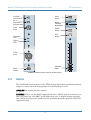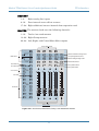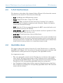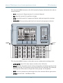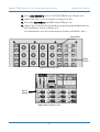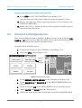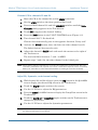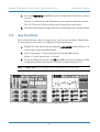
1
Important Safety Instructions
1.
2.
3.
4.
5.
6.
7.
Read these instructions.
Keep these instructions.
Heed all warnings.
Follow all instructions.
Do not use this apparatus near water.
Clean only with dry cloth.
Do not block any ventilation openings. Install in
accordance with the manufacturer’s instructions.
8. Do not install near any heat sources such as
radiators, heat registers, stoves, or other
apparatus (including amplifiers) that produce heat.
9. Do not defeat the safety purpose of the polarized
or grounding-type plug. A polarized plug has two
blades with one wider than the other. A groundingtype plug has two blades and a third grounding
prong. The wide blade or the third prong are
provided for your safety. If the provided plug does
not fit into your outlet, consult an electrician for
replacement of the obsolete outlet.
10. Protect the power cord from being walked on or
pinched particularly at plugs, convenience
receptacles, and the point where they exit from
the apparatus.
11. Only use attachments/accessories specified by
the manufacturer.
12. Use only with a cart, stand, tripod, bracket, or
table specified by the manufacturer, or sold with
the apparatus. When a cart is used, use caution
when moving the cart/apparatus combination to
avoid injury from tip-over.
13. Unplug this apparatus during lightning storms or
when unused for long periods of time.
14. Refer all servicing to qualified service personnel.
Servicing is required when the apparatus has
been damaged in any way, such as power-supply
cord or plug is damaged, liquid has been spilled
or objects have fallen into the apparatus, the
apparatus has been exposed to rain or moisture,
does not operate normally, or has been dropped.
15. This mixer has been designed with Class-I
construction and must be connected to a mains
socket outlet with a protective earthing connection
(the third grounding prong).
16. This mixer has been equipped with an all-pole,
rocker-style AC mains power switch. This switch is
located on the rear panel and should remain
readily accessible to the user.
17. This apparatus does not exceed the Class A/Class
B (whichever is applicable) limits for radio noise
emissions from digital apparatus as set out in the
radio interference regulations of the Canadian
Department of Communications.
ATTENTION — Le présent appareil numérique
n’émet pas de bruits radioélectriques dépassant las
limites applicables aux appareils numériques de
class A/de class B (selon le cas) prescrites dans le
réglement sur le brouillage radioélectrique édicté
par les ministere des communications du Canada.
18. Exposure to extremely high noise levels may
cause permanent hearing loss. Individuals vary
considerably in susceptibility to noise-induced
hearing loss, but nearly everyone will lose some
hearing if exposed to sufficiently intense noise for
a period of time. The U.S. Government’s
Occupational Safety and Health Administration
(OSHA) has specified the permissible noise level
exposures shown in the following chart.
According to OSHA, any exposure in excess of
these permissible limits could result in some
hearing loss. To ensure against potentially
dangerous exposure to high sound pressure
levels, it is recommended that all persons
exposed to equipment capable of producing high
sound pressure levels use hearing protectors
while the equipment is in operation. Ear plugs or
protectors in the ear canals or over the ears must
be worn when operating the equipment in order to
prevent permanent hearing loss if exposure is in
excess of the limits set forth here.
Mackie TT24 Digital Live Console Quickstart Guide
Table of Contents
Chapter 1:
Chapter 2:
Chapter 3:
Chapter 4:
Introduction ..................................................................................... 5
1.1
Evolution of the TT24 Console ...................................................... 5
1.2
Summary of Features .................................................................... 5
1.2.1 Rear Panel Connections...................................................... 6
1.2.2 DSP Functionality............................................................... 8
1.3
Terminology and Conventions..................................................... 10
TT24 Interface ............................................................................... 11
2.1
Channel Strip ............................................................................... 11
2.2
Banks ............................................................................................ 12
2.3
V-Pot Control Area ...................................................................... 14
2.4
QuickMix Area ............................................................................. 14
2.5
Snapshots ..................................................................................... 16
2.6
Flex Groups and Master .............................................................. 16
2.7
Matrix-Plus .................................................................................. 17
2.8
Utility Area .................................................................................. 18
2.9
TT Control Software .................................................................... 18
Quickstart Tutorial ..................................................................... 19
3.1
Connect Amplifier/Speakers........................................................ 19
3.2
Connect a Mic............................................................................... 20
3.3
Connect a CD/Tape Device .......................................................... 23
3.4
Aux Functions .............................................................................. 25
3.5
Effects ........................................................................................... 27
TT24 Specifications.................................................................... 28
Appendix A: TT24 Configurations and Block Diagrams .................. 32
iii
Mackie TT24 Digital Live Console Quickstart Guide
Print Version:
Part No. 0012118 Rev. C 7/04
Web Version:
Part No. SW0134 Rev. C 7/04
©2004 LOUD Technologies Inc.
All Rights Reserved.
iv
Mackie TT24 Digital Live Console Quickstart Guide
Chapter 1: Introduction
1.1
Evolution of the TT24 Console
The professional live sound industry has been revolutionized over the past few
years by high-end digital consoles. However, mid-size digital consoles have
tended to emphasize studio applications with user interfaces encumbered by
features (i.e., DAW control) not critical for live applications. Some of these
consoles conceal their real cost by requiring the purchase of additional cards to
supplement their limited physical I/O.
The TT24 Digital Live Console is a mid-size digital mixer optimized for live
sound applications. We have used our extensive expertise and experience designing analog mixers to produce a powerful, easy-to-use digital console for a
wide range of applications and budgets:
• theaters and houses of worship;
• permanent concert installations;
• professional live music touring companies.
1.2
Summary of Features
• 24-bit/96 kHz mixing console designed for live applications
• 24 mic/line inputs with 4-band EQ/comp/gate/HPF/polarity invert (can be
stereo linked)
• Eight line inputs with 4-band EQ (can be stereo linked)
• Instant recall of 99 snapshots with filtering
• Rear panel connections: 36x28 analog I/O; 28x28 digital I/O
• QuickMix section with 5.5-inch touch LCD, 12 push-button rotary encoders,
and QuickMix buttons
• 29 100-mm motorized faders
• 28 multi-function V-Pots
• 12 Aux sends with 4-band parametric EQ + dual kill filters and compressor/
limiter
5
Mackie TT24 Digital Live Console Quickstart Guide
Introduction
• Left-Right and CTR/Mono outputs with 4-band EQ + dual kill filters and
compressor/limiter
• Aux Mode enables instant monitor mixing
• 11x8 Matrix-Plus with patchable inputs
• Eight user-definable flex-groups
• 2 expansion card slots
• Dual-console linking for a maximum 96 input console
• TT control software to control and view console parameters via PC
1.2.1
Rear Panel Connections
Analog I/O
Figure 1-1 shows the rear panel analog I/O connectors except for the Group/
Matrix outputs, which are shown in Figure 1-2.
15
14
13
12
11
10
9
8
7
6
5
4
3
2
1
LINE
LINE
LINE
LINE
LINE
LINE
LINE
LINE
LINE
LINE
LINE
LINE
LINE
LINE
LINE
INSERT
INSERT
INSERT
INSERT
INSERT
INSERT
INSERT
INSERT
INSERT
INSERT
INSERT
INSERT
INSERT
INSERT
INSERT
TALKBACK
CD/TAPE A
MAINS OUT
LEFT
RIGHT
AUX SENDS
12 Aux
Sends
CTR/MONO
C
L
12
11
10
9
8
7
6
LINE INPUTS
5
5
3
4
3
2
1
MONITOR
Monitor
Outputs
R
IN
OUT
L
Main Outputs
Talkback
Input
R
8
7
6
4
2
1
L
R
8 Analog Line Inputs
CD/Tape A
CD/Tape B
Inputs/Outputs Inputs
Figure 1-1 Analog I/O
GROUP/MATRIX OUT
8
24 Mic, Line
and Insert
Analog
Inputs
7
6
5
4
3
Group/Matrix Outputs
Figure 1-2 Group/Matrix connectors
6
2
1
M
Mackie TT24 Digital Live Console Quickstart Guide
Introduction
Inputs
• 24 mic/line inputs with inserts (mic = balanced XLR; line = balanced TRS;
inserts = unbalanced Tip Send-Ring Return)
• Eight analog line inputs (balanced TRS)
• CD/Tape A (unbalanced RCA)
• CD/Tape B (balanced TRS)
• Talkback Mic In (balanced XLR)
Outputs
• Main Left, Right, Center/Mono Outputs (balanced XLR)
• 8 Group/Matrix Outputs (balanced XLR)
• 12 Auxiliary Outputs (balanced TRS)
• CD/Tape A Outputs (unbalanced RCA)
• L-R and Mono Monitor Outputs (balanced TRS)
• Headphone Output (Stereo TRS)
Digital I/O
The rear panel digital I/O (Figure 1-3) consists of the following connectors and
features:
• ADAT optical: 24 channels @ 44.1/48 kHz; 12 channels @ 88.2/96 kHz
• Stereo AES/EBU or S/PDIF with switchable input sample rate conversion
and output dithering
• Word Clock
• MIDI
• USB connection for TT control software
• Two expansion cards slots offer several options:
OPT24t – expands console for 24-channel 96 kHz ADAT optical operation
U100 – links two TT24 consoles for 96-channel, 48-fader operation
UFX2 – provides four additional effects processors or 24 channel strips with
DSP for the Digital bank
LP48 – EQ and loudspeaker processor card featuring Lake Technology’s DSP
More options may be offered in the future.
7
Mackie TT24 Digital Live Console Quickstart Guide
MIDI
In/Out
USB
Input
MIDI
Introduction
Word Clock
In/Out
USB
ADAT Optical
I/O connectors
ADAT DIGITAL I/O
OUT
C
OUT
A
C
B
IN
A
AES/EBU
OUT
WORD
CLOCK
K
OUT
Power
On/Off
IN
B
IN
SPDIF
IN
OUT
IN
AES/EBU
In/Out
POWER
S/PDIF
In/Out
EXPANSION
~100-240VAC
50-60Hz 300W
FUSE: 6A/250V
CARD A
AC Power
Inlet
CARD B
Expansion
card slots
Figure 1-3 Digital I/O and expansion card slots
1.2.2
DSP Functionality
The TT24 is loaded with DSP horsepower that is distributed on inputs and outputs in a manner optimized for live sound:
24 Mic/Line Inputs
• Polarity invert
• Variable High-Pass Filter
• Gate/Expander
• Compressor/Limiter
• 4-band parametric EQ
• Stereo linking
8
Mackie TT24 Digital Live Console Quickstart Guide
8 Line Inputs
• 4-band parametric EQ
• Stereo linking
Main Outputs (Left, Right, CTR/Mono)
• Compressor/Limiter
• 4-band parametric EQ with dual kill filters
• L-R + Mono or LCR modes of operation
12 Aux Sends
• Compressor/Limiter
• 4-band parametric EQ with dual kill filters
• Stereo linking
8 Flex-Groups with 8 Assignable DSP Blocks
• Compressor/Limiter
• 4-band parametric EQ
• Mono, Stereo, LCR, and VCA modes of operation
8 Matrix Outputs
• Each output can have 600 ms delay.
4 Internal Stereo Effects
• Reverb
• Gated Reverb
• Mono/Stereo/Ping-Pong Delay
• Chorus
• Flanger
9
Introduction
Mackie TT24 Digital Live Console Quickstart Guide
1.3
Introduction
Terminology and Conventions
The following terms and conventions are used throughout this manual.
• Touchscreen and console controls are represented in bold type using their
exact spelling and capitalization (i.e., press the ANLG bank button).
• Touchscreen and console areas are represented by capital letters in plain
type (i.e., press the PAN button in the V-POT CONTROL area).
• Activate pertains to switches/buttons that toggle between two values and
means “press the button until it lights.”
• Deactivate pertains to switches/buttons that toggle between two values and
means “press the button until it is not lit.”
• Touch pertains to selection on the Touchscreen (i.e., Touch the EQ button).
10
Mackie TT24 Digital Live Console Quickstart Guide
Chapter 2: TT24 Interface
The TT24 has an intuitive easy-to-use interface. It maintains an “analog mentality,” which leverages off the engineer’s experience, while providing all the
advantages of digital functionality.
The design mandate for the TT24 console interface is simply stated:
Provide quick, intuitive access to any primary live mixing function
with no more than two button presses, both within easy reach of the
engineer’s two hands.
Make the Touchscreen menu structure flat: no “forward” and “back”
buttons or menus to wade through to access the desired function.
The following sections summarize the TT24’s major functional categories.
2.1
Channel Strip
Channel strip means one of the 24 vertical areas bounded at the bottom by a
fader and at the top by the LINE mic/line level switch. Each channel strip
can control one input at a time from one of four banks.
The top section of each channel strip (Figure 2-1) has analog controls for mic/
line input switching, 48 V phantom power activation, mic/line gain control, and
signal/overload LED indication.
Below that, each channel has a virtual potentiometer (V-Pot), MUTE, SELECT,
and SOLO backlit buttons, and a 100 mm motorized fader.
The V-Pot, which performs multiple channel functions (i.e., auxiliary sends
and panning), consists of a push-button rotary encoder surrounded by a 16segment LED ring (see V-Pot Control Area on page 14 for details).
11
Mackie TT24 Digital Live Console Quickstart Guide
Line/Mic
level button
Mute
button
LINE
48 V
phantom
power button
48V
Bank/
Channel
description
30
40
Gain
knob
Overload
LED
Signal
LED
U
TT24 Interface
60
Select
button
-
GAIN
Solo
button
MUTE
1
25
LINE
INPUT
AUX
SEND
1
SELECT
SOLO
OL
SIG
1
V-Pot
knob
Mute
button
Channel
fader
MUTE
Figure 2-1 Channel strip: top (left), bottom (right)
2.2
Banks
The four Bank select buttons on the TT24 change the function of the 24 channel
strips to control the following groups of channels (Figure 2-2):
ANALOG: 24 analog mic/line inputs
DIGITAL: There are 24 digital inputs from three ADAT optical connectors on
the rear panel (44.1/48 kHz). At 96 kHz, there are 12 digital inputs from the
three built-in connectors; another 12 are available from the optional ADAT I/O
expansion card.
12
Mackie TT24 Digital Live Console Quickstart Guide
TT24 Interface
RETURNS:
1–8:
Eight analog line inputs
9–16:
Four internal stereo effects returns
17–24: Eight additional return channels from expansion card
MASTER: The masters bank uses the following channels:
1–12:
Twelve Aux send masters
13–20: Eight Group masters
22–24: Left, Right, and Center/Mono Main outputs
Group Mute buttons
ANALOG
ANLG
MUTE
MUTE
MUTE
MUTE
DIGITAL
DGTL
1
2
3
4
CTR/
MONO
Bank Select
Clear Solo and
PFL buttons
GROUP ASSIGN/SELECT
Group Assign/Select buttons
Master Left/Right Assign button
RETURNS
RTNS
5
6
7
8
L/R
MASTER
MSTR
SELECT
SELECT
SELECT
SELECT
SELECT
Master Select button
CLEAR
SOLO
PFL
SOLO
SOLO
SOLO
SOLO
MASTER
Group Select buttons
TRIM
PAN
Group Solo buttons
V-POT
CONTROL
V-Pot Control
Aux Mode
Master Center/Mono Assign button
METERS
HPF
AUX
PAN
AUX
MODE
1
2
3
4
AUX
SENDS
5
6
7
8
Aux Sends
9
11
FX1
FX2
FX3
FX4
10
12
Group
p Faders
Master Fader
Figure 2-2 V-Pot Control, Bank Select, Group, Aux and Master sections
13
Mackie TT24 Digital Live Console Quickstart Guide
2.3
TT24 Interface
V-Pot Control Area
The buttons to the right of the channel faders (Figure 2-2) selects the current
function for the channel V-Pots from the following:
• PAN: Left/Right and LCR panning control
• TRIM: Digital Trim has a range of ±15 dB
• METERS: High-resolution channel metering. Push the V-Pot and the
meter reverses to display compressor gain reduction. Rotate the knob to
control the threshold settings.
• HPF: Push the V-Pot to engage/disengage the HPF; rotate the knob to adjust frequency between 20–400 Hz.
• AUX SENDS 1–12: Rotate the V-Pot to control send level; push the V-Pot
to toggle pre/post fader for that send.
• AUX PAN: Control panning of stereo linked axes
• AUX MODE: Aux mode is the only blue button on the console and effectively
turns the TT24 into a powerful, dedicated monitor mixer by providing aux
mixing on the faders. In this mode, the 24 channel faders act as channel aux
sends and the 4 group faders act as auxiliary master sends.
2.4
QuickMix Area
The upper-right of the console, below the 5.5-inch Touchscreen, is called the
QuickMix area (Figure 2-3). It consists of 12 push-button rotary encoders and
eight buttons, which provide fast navigation of the QuickMix section
It is important to note:
• The only adjustable controls on the Touchscreen are buttons that toggle a
value on/off. All knobs represented on the Touchscreen are controlled by
corresponding QuickMix knobs. If any of the 12 knobs are missing from the
Touchscreen, the corresponding QuickMix knob has no function.
• Any Touchscreen knob colored white instead of black denotes a dual function available by pushing the corresponding QuickMix knob. This function
varies with the control.
14
Mackie TT24 Digital Live Console Quickstart Guide
TT24 Interface
The four QuickMix buttons on the left instantly display information for the selected channel:
• FAT: overview of all parameters of a selected channel
• EQ: detailed control of equalizer settings
• DYN: detailed control of compressor/limiter and gate/expander settings
• GRP/AUX: Group routing and Aux level control and pre/post selection
QuickMix
section
Snapshot
section
AUX
MSTR
FAT
RECALL
SNAPSHOTS
EQ
SNAP
STORE
DYN
EFX
SETUP
HELP
GRP/
AUX
MATRIX
CTRL
UTIL
COPY
PASTE
Figure 2-3 QuickMix and Touchscreen
The four QuickMix buttons on the right access configuration mixing tasks:
• AUX MSTR puts all 12 Aux master sends on the 12 knobs.
• SNAP provides detailed control of the 99 snapshots including naming, locking and filtering. All elements can be filtered out of a snapshot. For example
filtering out all but mute will provide mute groups via snapshots.
• EFX accesses parameters and setup of the four internal effects processors.
• MTRX accesses the 11x8 Matrix-Plus.
15
Mackie TT24 Digital Live Console Quickstart Guide
2.5
TT24 Interface
Snapshots
The TT24 includes a robust snapshot feature that captures the state of the console:
• 99 snapshots
• fast store/recall surface control
• detailed snapshot filtering to store/recall only selected parameters and
channels
The snapshot controls are in the upper-right area beside the QuickMix buttons
(Figure 2-3).
2.6
Flex Groups and Master
The TT24 has four Group channel strips and a master strip (Figure 2-2). Each
Group has a V-Pot (to control group pan), MUTE, SELECT, SOLO buttons, and
a 100 mm motorized fader on the console surface. The four Group strips control
either Groups 1–4 or 5–8. The currently selected Group bank is indicated by
the GROUP ASSIGN/SELECT buttons.
Changing the Group Bank
Press any of the GROUP ASSIGN/SELECT buttons to select that Group bank.
The GROUP ASSIGN/SELECT buttons illuminate 1–4 or 5–8 and cause the
faders and buttons to snap to their previous Group bank settings.
Group Assignment
Press and hold a GROUP ASSIGN/SELECT button and press the channel
SELECT buttons to add/subtract channels from that Group. This method is
used for all of the GROUP ASSIGN/SELECT buttons (Groups 1–8, L-R and
CTR/Mono).
Group Parameter Control
Press a GROUP SELECT button to access that Group’s settings and controls
in the QuickMix section just like an input channel.
16
Mackie TT24 Digital Live Console Quickstart Guide
2.7
TT24 Interface
Matrix-Plus
Matrix-Plus is a unique and powerful 11x8 matrix mixing tool that delivers extremely flexible matrix mixing. The matrix can only be activated by pressing
the MATRIX button on the right side of the QuickMix area (Figure 2-3).
Once activated, the matrix uses the Group outputs. Like most 11x8 matrices, the
11 default inputs to each matrix are Groups 1–8, Left, Right, and Center. However, Matrix-Plus provides the unique ability to patch other signals into the matrix. Press the desired Group QuickMix knob to display the screen in the right
side of Figure 2-4 to select the desired signals.
Figure 2-4 Matrix screens
The available matrix input signals are:
• Analog inputs 1–24 pre/post fader
• Digital inputs 25–48 pre/post fader
• Line inputs 1–8 pre/post fader
• Internal effects returns 1L-4R pre/post fader
• Groups 1–8 Mono, Left, Right, Center (if available)
• Main Left, Right or CTR/Mono post fader
• Expansion card return 1–8
• Stereo inputs Left and Right pre/post fader
Each matrix also has up to 600 ms delay for delayed stack applications.
17
Mackie TT24 Digital Live Console Quickstart Guide
2.8
TT24 Interface
Utility Area
At the top of the console, the UTILITY area contains:
Talkback: Mic preamp gain setting knob; signal (SIG) and overload (OL) LEDs
Monitor: Analog level control for the Left, Right, Mono TRS rear panel outputs
Phones: Analog level control for the front-mounted headphone jack
UTILITY
U
30
U
OL
40
20
SIG
U
+60dB
OFF
TALKBACK
MAX
MONITOR
OFF
MAX
PHONES
Figure 2-5 Utility area
2.9
TT Control Software
The TT control software expands the control possibilities for the TT24 console
by providing:
• Remote control of all TT24 functions from a PC connected via USB.
• Improved metering and graphics than can be seen on the Touchscreen.
• Remote Show/Venue/Preset management and console–>console backup/restore.
• Console firmware upgrade capability.
The TT24 connects to the PC via a USB cable (six-ft cable supplied). The minimum PC requirements are summarized below.
Table 2-1 Minimum PC Requirements
Screen Resolution
Processor Speed
Operating System
1024 x 768
600 MHz
Windows 2000 or XP
The main screens of the TT control software mirror and elaborate the Touchscreens. The TT control screens can be set to operate independently or to track
the Touchscreen. When they are independent, two users may control the TT24,
one from the console and one from the computer. To adjust this setting from the
Touchscreen (can also be adjusted from TT control): press the QuickMix SETUP
button, touch the GENERAL button from the MENU SELECTION screen, then
touch to select PC AUTO FOLLOW to synchronize the TT control software with
the Touchscreen (de-select the checkbox to make them independent).
18
Mackie TT24 Digital Live Console Quickstart Guide
Chapter 3: Quickstart Tutorial
This Quickstart Tutorial will help you begin using the TT24 quickly and easily
by providing step-by-step instructions for its most commonly utilized tasks.
Rest assured that our team of design engineers has verified these instructions!
Before beginning the Quickstart Tutorial, please read:
• Chapter 1: Introduction to learn about the TT24’s basic attributes, and terminology/conventions for the console, Touchscreen, and user guide.
• Chapter 2: TT24 Interface provides a good overview of the TT24’s important
functional entities.
It may also be helpful to refer to Appendix A: TT24 Configurations and Block
Diagrams to see how several useful complete systems are interconnected.
3.1
Connect Amplifier/Speakers
1. Plug in a left-right pair of amps/speakers into the MAINS OUT LEFT
and RIGHT XLR connectors (Figure 3-1).
2. Connect an amp/speaker to AUX SEND 1.
3. Plug in headphones.
MAINS OUT
LEFT
RIGHT
TALKBACK
AUX SENDS
CD/TAPE A
12 Aux
Sends
CTR/MONO
C
L
12
11
10
9
8
7
6
LINE INPUTS
5
4
3
2
1
MONITOR
L
R
8
7
6
5
3
2
1
L
R
R
IN
Main Outputs
OUT
4
CD/Tape A
CD/Tape B
Inputs/Outputs Inputs
Figure 3-1 Mains and Aux Sends Outputs
19
M
Mackie TT24 Digital Live Console Quickstart Guide
3.2
Quickstart Tutorial
Connect a Mic
This section tells you how to connect a mic to channel 1, set the gain, route to
groups/auxes, and engage/adjust the variable high-pass filter.
Connect mic to channel 1
1. Plug a mic into channel 1’s XLR input (top-right of rear panel).
2. Press the ANLG bank select button (right of Figure 3-2).
3. Set the LINE switch to the up (mic) position (left of Figure 3-2).
Line/Mic
level button
ANLG
DIGITAL
DGTL
RETURNS
RTNS
MASTER
MSTR
LINE
Bank Select
48 V
phantom
power button
Gain
knob
ANALOG
48V
Clear Solo and
PFL buttons
30
20
40
U
U
CLEAR
SOLO
TRIM
60
-20dB
PFL
+40dB
GAIN
PAN
V-POT
CONTROL
V-Pot Control
METERS
HPF
Figure 3-2 Top of channel strip (left); Bank select, Clear Solo, PFL, V-Pot control (right)
4. Set the 48V switch to the down position if the mic uses phantom power;
set it to the up position otherwise.
Set the channel gain
5. Activate the PFL button (right of Figure 3-2).
6. Activate channel 1’s SOLO button (above fader) to set gain.
7. Provide a representative signal to the mic, watch the meters to the right
of the Touchscreen, and listen in phones (the phones level is in the
UTILITY area).
The level should be between –7 and –10 dBFS.
8. Press SOLO again or CLEAR SOLO to unsolo.
20
Mackie TT24 Digital Live Console Quickstart Guide
Quickstart Tutorial
Route channel 1 to Main output, Group 1, and Aux 1
9. Press and hold the L/R button in the GROUP ASSIGN area (Figure 3-3)
and activate channel 1’s SELECT button.
All the channel SELECT buttons light, indicating that all channels are
routed to the Main output. You should hear your mic in the main speakers via the master fader.
Now, let's route the mic through Group 1 instead of directly to L-R:
10. Press and hold the L/R button in the GROUP ASSIGN area and deactivate channel 1’s SELECT button (so it is not lit).
Channel 1 no longer sends signal to L/R.
11. Press and hold the GRP1 button in the GROUP ASSIGN area and activate channel 1’s SELECT button.
The mic is now routed to Group 1.
12. Press and hold the L/R button in the GROUP ASSIGN area and activate
Group 1’s SELECT button.
Group 1 is now assigned to L/R.
Use the channel, Group, and Master fader to listen to the mic signal in
the L/R speakers.
Group Mute buttons
ANALOG
ANLG
MUTE
MUTE
MUTE
MUTE
DIGITAL
DGTL
1
2
3
4
CTR/
MONO
Bank Select
Clear Solo and
PFL buttons
GROUP ASSIGN/SELECT
Group Assign/Select buttons
Master Left/Right Assign button
RETURNS
RTNS
5
6
7
8
L /R
MASTER
MSTR
SELECT
SELECT
SELECT
SELECT
SELECT
Master Select button
PFL
SOLO
SOLO
SOLO
SOLO
MASTER
Group Select buttons
CLEAR
SOLO
Group Solo buttons
TRIM
PAN
V-POT
CONTROL
V-Pot Control
Aux Mode
Master Center/Mono Assign button
METERS
HPF
AUX
PAN
AUX
MODE
1
2
3
4
AUX
SENDS
5
6
7
8
Aux Sends
9
FX1
FX2
10
Figure 3-3 Aux, Group, and Master areas
21
Mackie TT24 Digital Live Console Quickstart Guide
Quickstart Tutorial
13. Press AUX SENDS 1 in the V-POT CONTROL area (Figure 3-3).
14. Adjust the Aux 1 level on channel 1 using the V-Pot.
15. Press the AUX MSTR QuickMix button (Figure 3-4).
16. Adjust Aux 1’s master level with the corresponding QuickMix knob (see
the Aux Master screen in Figure 3-5).
You should hear your mic in the monitor speaker attached to Aux 1.
Aux Master
button
FAT
AUX
MSTR
EQ
SNAP
DYN
EFX
SETUP
HELP
GRP/
AUX
MATRIX
CTRL
UTIL
COPY
PASTE
RECALL
SNAPSHOTS
Figure 3-4 QuickMix area
AUX 1
Master level
Figure 3-5 Aux Master screen
22
STORE
Utility
button
Mackie TT24 Digital Live Console Quickstart Guide
Quickstart Tutorial
Engage and adjust the variable high-pass filter
17. Press HPF in the V-POT CONTROL area (Figure 3-2).
Now the high-pass filter can be adjusted with the channel V-Pots.
18. Engage the high-pass filter by pressing channel 1’s V-Pot knob so the
bottom red LED lights.
19. Rotate the V-Pot to adjust the filter in the range 20–400 Hz to remove
unwanted low frequencies.
3.3
Connect a CD/Tape Device
This section illustrates how to connect a CD/tape device to the dedicated CD/
TAPE A or B connectors (A = RCA, B = TRS), and to channels 23/24 to demonstrate stereo linking and channel strip processing.
Connect CD to CD/Tape input
1. Connect the CD player into CD/TAPE A or B (Figure 3-1).
2. Press the UTIL button (Figure 3-4).
Stereo
Input
Assign
Figure 3-6 Stereo input assign
3. Touch STEREO INPUT ASSIGN on the Touchscreen (Figure 3-6).
4. Touch TAPE/CD A or TAPE/CD B in the INPUT SELECTION area
(Figure 3-6).
5. Touch to activate L/R in the GRP ASSIGN area to route the mains.
6. Adjust MUTE and SOLO from the Touchscreen.
7. Adjust the stereo input fader to desired level from its QuickMix knob.
23
Mackie TT24 Digital Live Console Quickstart Guide
Quickstart Tutorial
Connect CD to channels 23 and 24
1. Move the CD to the channel 23 and 24 LINE connectors.
2. Set the LINE switch to the down position (line level).
3. Press and hold channel 23 and 24’s SELECT switches until the Link
Channels dialog appears in the Touchscreen.
4. Touch OK to approve the channel linking.
5. Press the PAN button in the V-POT CONTROL area (Figure 3-3).
6. Turn channel 23’s V-Pot hard left.
Channel 24 automatically pans in the opposite direction. Pretty cool!
7. Activate the SOLO button above the fader on either channel to solo.
The linked channel does not also solo.
8. Adjust the channel’s GAIN knob and watch the meters to the right of
the Touchscreen.
The level should be between –7 and –10 dBFS.
9. Repeat steps 7 and 8 for the other channel in the linked pair.
NOTE: Stereo linking always operates on a consecutive odd/even channel pair. The odd
channel’s parameters are copied to the even channel except Pan, which is inversely
linked (i.e., hard left on odd channel translates to hard right on even channel).
Adjust EQ, Dynamics, and channel routing
1. With channel 23 and 24 selected, press the EQ button in the QuickMix
area to display the channel EQ screen in the Touchscreen.
2. Touch the EQ IN toggle switch on the screen.
3. Use the 12 V-Pots to adjust the EQ parameters.
4. Press the DYN QuickMix button to display the Comp/Gate screen in the
Touchscreen.
5. Touch the GATE IN or COMP IN toggle switches on the Touchscreen to
engage the processors.
6. Use the 12 V-Pots to adjust the dynamics parameters.
NOTE: Press the Gate or Compressor graph on the Touchscreen to access a larger view of
the individual dynamics processors.
24
Mackie TT24 Digital Live Console Quickstart Guide
Quickstart Tutorial
7. Press the GRP/AUX QuickMix button to display the Group/Aux routing
screens.
Groups 1–8 buttons on the Touchscreen are used for channel routing.
The 12 V-Pots are used to adjust the Channel Aux send levels.
8. Push the V-Pot knobs to toggle each Aux send between pre- and post-fader.
3.4
Aux Functions
This section discusses how to setup, route, and mix the Aux buses. Each of the
12 Aux masters have their own EQ and compressor/limiter.
1. Display the Aux masters by pressing the AUX MSTR button (Figure 3-4)
to the right of the QuickMix knobs.
2. Select Aux master 1 by pressing the top-left QuickMix knob.
Figure 3-7 (left) shows Aux 1 selected.
3. Touch the EQ grid or press the EQ QuickMix button to display the EQ
output parameters for selected Aux send 1 (right of Figure 3-7).
NOTE: The EQ IN/OUT button is located on the upper right of the Touchscreen.
Figure 3-7 Aux Master (left) and EQ (right) screens
25
Mackie TT24 Digital Live Console Quickstart Guide
Quickstart Tutorial
The EQ has six bands:
• two full parametric bands (bands 2 and 3);
• high- and low-shelf filters (bands 1 and 4);
• two Kill filters (bands 5 and 6) to remove narrow bands of unwanted
frequencies. Push the Kill filter knobs to cycle through -6, -12, or
-18 dB. As the amount of cut increases, the filter Q increases (i.e.,
bandwidth narrows). Turn the knob to adjust the frequency.
The channel aux levels are set with the channel V-Pots by pressing the desired
Aux number in the V-POT CONTROL area. All 12 Aux levels for a selected
channel can be set by pressing the GRP/AUX QuickMix button.
Aux Routing Examples
To send mic channel 1 to all monitors:
1. Press channel 1’s SELECT button.
2. Press the GRP/AUX QuickMix button.
3. Adjust the QuickMix knobs to set each Aux level.
To set one monitor mix:
1. Press the desired Aux number button in the AUX SENDS area.
2. Use each channel’s V-Pots to set the mix.
26
Mackie TT24 Digital Live Console Quickstart Guide
3.5
Quickstart Tutorial
Effects
Four effects processors can each use one of the following effects: reverb, reverb
through gate, mono/stereo/ping pong delay, chorus, and flange. The default
effect sends are Aux sends 9–12 but any Aux or Matrix sends can be used. The
effect returns are on the Returns bank.
1. Press the ANLG bank button.
2. Press AUX SENDS 9 in the V-POT CONTROL area.
3. Turn channel 1’s V-Pot to 3:00 to send channel 1 to Aux 9.
4. Press the EFX button in the QuickMix area.
The INTERNAL effects screen displays on the Touchscreen (left of
Figure 3-8).
Figure 3-8 Internal Effects and Reverb screens
5. Touch the Reverb’s Edit button to edit its parameters on its own screen
(right of Figure 3-8).
6. Touch EFX IN to activate the reverb.
7. Press the RTRNS bank button.
8. Speak into the mic and increase the Returns levels (INT EFX 1L and
INT EFX 1R) until you hear sufficient reverb.
27
Mackie TT24 Digital Live Console Quickstart Guide
Chapter 4: TT24 Specifications
Analog
Mic Preamp
Frequency response
+0, -2 dB, 10 Hz to 20 kHz (Mic In to Insert Out)
Distortion (THD + N)
< 0.003% @ +20 dBu output, 20 Hz to 20 kHz
(Mic In to Insert Out)
Noise
20 Hz to 20 kHz BW (150 Ω source impedance)
Equivalent Input Noise (EIN)
–128 dBu
Residual Noise
–103 dBu (Mic In to Insert Out @ 0 dB gain)
Common Mode Rejection Ratio (CMRR) >60 dB @ 1 kHz, gain @ maximum (Mic In to Insert Out)
Rise Time
< 3 µs
Slew Rate
3.6 V/µs
Input Gain Control Range
Mic In
0 dB to +60 dB
Line In
–20 dB to +40 dB
Phantom Power
48 VDC
Input Impedance
Mic Input
2 kΩ, balanced
Line Input
10 kΩ
Aux Returns, CD/Tape A and B
10 kΩ
Maximum Input Level
Mic Input
+22 dBu
Line Input
+22 dBu
Aux Returns, CD/Tape A and B
+22 dBu
28
Mackie TT24 Digital Live Console Quickstart Guide
TT24 Specifications
Output Impedance
L/R/C-Mono, Group/Matrix Out
150 Ω
Aux Send, Monitor Out
150 Ω
CD/Tape A and B Out
600 Ω
Maximum Output Level
Insert Out
+22 dBu
L/R/C-Mono, Group/Matrix Out
+26 dBu
Aux Send, Monitor Out
+21 dBu
CD/Tape A and B Out
+22 dBu
Phones Out
500 mW into 100 Ω
System
Frequency Response (Gain at unity)
Mic Input to Main Output
+0, –1 dB, 10 Hz to 20 kHz @ 44.1 kHz
+0, –2 dB, 10 Hz to 40 kHz @ 96 kHz
+0, –0.5 dB, 14 Hz to 27.5 kHz @ 96 kHz
Distortion (THD + N)
Mic Input to Main Output
< 0.02% @ +4 dBu input, 44.1 kHz, 10 Hz to 20 kHz
< 0.03% @ +4 dBu input, 96 kHz, 10 Hz to 20 kHz
AES Input with SRC to AES Output
< 0.0002% @ –10 dBFS input, 44.1 kHz, 10 Hz to 22.05 kHz
< 0.0006% @ –10 dBFS input, 96 kHz, 10 Hz to 48 kHz
Signal to Noise Ratio
–78 dBu (ref. +4 dBu Mic In to Main Out)
Dynamic Range
101 dB (Mic In to Main Out)
Maximum Voltage Gain
96 dB (Mic In to Main Out)
Crosstalk
Adjacent Inputs
–110 dB @ 1 kHz
Adjacent Main Outputs
–95 dB @ 1 kHz
Adjacent Aux Outputs
–115 dB @ 1 kHz
29
Mackie TT24 Digital Live Console Quickstart Guide
TT24 Specifications
Digital
Faders
Type
100 mm motorized, movement sensitive
Resolution
128 steps
Sampling Frequency
44.1, 48, 88.2, 96 kHz (Internal and External)
Digital Signal Processing
32-bit floating point resolution
Propagation Delay (Mic In to Main Out)
< 3.8 ms @ 44.1 kHz
< 1.7 ms @ 96 kHz
Word Clock Input
Minimum Level
0.4 V p-p
Duty Cycle
50%
Impedance
75 Ω
External Word Clock Lock Range
44.1 kHz
48 kHz
88.2 kHz
96 kHz
= 42.5 kHz – 45.8 kHz
= 46.4 kHz – 49.4 kHz
= 85.0 kHz – 90.7 kHz
= 92.2 kHz – 98.2 kHz
Word Clock Output
Open Circuit Level
5 V p-p
Duty Cycle
50%
Impedance
75 Ω
AES Input (IEC-60958-3)
Sample Rate with SRC
32 kHz – 96 kHz
Sample Rate without SRC
System sample rate exactly
Maximum Level
0.4 V p-p
Impedance
110 Ω, transformer coupled
AES Output (IEC-60958-3)
Sample Rate
System rate or switchable half system rate
Level into 110 Ω
5 V p-p
Impedance
110 Ω, transformer coupled
30
Mackie TT24 Digital Live Console Quickstart Guide
TT24 Specifications
S/PDIF Input
Sample Rate with SRC
32 kHz – 96 kHz
Sample Rate without SRC
System sample rate exactly
Minimum Level
0.4 V p-p
Impedance
75 Ω
S/PDIF Output
Sample Rate
System rate or switchable half system rate
Level into 75 Ω
0.5 V p-p
Impedance
75 Ω, transformer coupled
General
AC Power Requirements
100–240 VAC, 50–60 Hz, auto-switching
Fuse
6 A/250 V
Operating Temperature
10ºC–40ºC (50ºF–104ºF)
Physical Dimensions
Height
10.4 in/265 mm
Width
42.6 in/1083 mm (including handles)
Depth
25.0 in/636 mm
Weight
71.0 lb/32.2 kg
Disclaimer
Since we are always striving to make our products better by incorporating new
and improved materials, components, and manufacturing methods, we reserve
the right to change these specifications at any time without notice.
31
Appendix A: TT24 Configurations and Block Diagrams
Microphones
24 Built-in
Optical Inputs
ONYX
800R
24 Built-in Mic/Line Inputs
ophones
TT24
Expansion Cards
1 - UFX2
Main Outs
(L/R/Mono)
In-Ear Monitor
System
Aux Outs
Stereo Power
Amplifier
Stereo Power
Amplifier
Left
Right
Floor Monitors
Figure A-1 48-channel TT24 system
mono monitor output
24 Built-in Mic/Line Inputs
headphones and monitor
for engineer
TT24
Aux Outs 1-12 stereo linked
Eight additional mono monitor mixes from Matrix-Plus
Figure A-2 TT24 system with in-ear monitors
32
In-Ear Monitor
System
Microphones
24 Built-in
Optical Inputs
ONYX
800R
Mic Preamps
24 Built-in Mic/Line Inputs
Microphones
Microphones
TT24
24 Built-in
24 Built-in Mic/Line Inputs
ONYX
800R
Mic Preamps
p
Expansion Cards
TT24
1 - U100 per TT24
In-Ear Monitor
System
1 - UFX2 per TT24
Main Outs
(L/R/Mono)
Aux Outs
Stereo Power
Amplifier
Left
Mono Power
Amplifier
Center
Stereo Power
Amplifier
Right
Floor
Monitors
Figure A-3 96-channel system with two TT24s
24 Built-in
Optical Inputs
ONYX
800R
Microphones
24 Built-in Mic/Line Inputs
ophones
expansion cards
UFX2
LP48
TT24
Two additional delay lines from
Lake Technology's LP48 card
Three-way stereo system from
Lake Technology's LP48 card
Figure A-4 Three-way stereo system using Lake Technology’s LP48 expansion card
33
48V
1
3
2
Analog Channels 1-24
MIC
LINE
INSERT
ADAT
IN (x3)
Gain
-
+
ADAT 13 (= ADAT 14-24)
ADC
Clip
ADC
Digi Insert
Digi Insert
Sig
Meter
Meter
Trim
(=Line Input 2-8)
Meter
High Pass
Gate
3
2
Comp
Reversible Digi Insert
4-Band
Para EQ
Channel Processing Analog Channel 1
Phase
Optional Stereo Link in Pairs
Digi Insert Return
Digi Insert Return
Digi Insert Return
Digi Insert Return
Channel 1 Level, Pan & Group Assign
Pan
Fader
Solo
Aux 2 (=Even#Aux)
Fader
Linked if
Aux 1/2
is stereo
Aux 1 (=Odd#Aux)
Pan
Pan
Grp 1Assgn
(=Grp 2-8)
LR Assgn
C Assgn
(=Analog 1-24, Digital 1-24, Line input 1-8, IFX Ret 1-8,
Slot A Ret 1-8)
Mute
Fader
Pre/Post
Linked if
Aux 1/2
is stereo
Pre/Post
Optional Stereo Link in Pairs
Talk
Solo
Matrix 1 Assgn
(=Mat 2-8)
Aux 1 Assgn
(=Odd#Aux)
Aux 2 Assgn
(=Even#Aux)
+
Mono
to Mains
24 Signals
(e.g. Replace built-in inputs
Analog 1-24 or Digital 1-24,
replace ouptuts, send to
Digital out, digi inserts, etc.)
Linked if Aux
1/2 is stereo
All controls directly linked, but pans linked inversely, with initial setting of full L
on odd channel, and full R on even channel (same applies to aux send pan).
Sig/Clip
LEDs
ADC
Mute
LR Assgn
(with Audio
Network Card)
Slot A only
or
Slot B only
Stereo Level
24 Signals - Selectable
(e.g. Analog 1-24 pre- or
post-processing, Digital124 outputs, digi inserts etc.)
Monitor Sel and any Digital Insert Return
Monitor Sel and any Digital Insert Return
1
All processing parameters linked, and true stereo compression.
Trim
(=Analog 2-24)
Digi Insert
Meter
To Level, Pan & Group Assign
To Level, Pan & Group Assign
To Level, Pan & Group Assign
To Level, Pan & Group Assign
To Level, Pan & Group Assign
To Level, Pan & Group Assign
To Level, Pan & Group Assign
To Level, Pan & Group Assign
To Level, Pan & Group Assign
SRC
Bypass
TALKBACK
MIC
To Level, Pan & Group Assign
To Level, Pan & Group Assign
3-Band
Para EQ
Line Input 1 Processing
Mic: 0 to +60 dB
Line: Ð20 to +40 dB
ADAT 1 (= ADAT 2-24)
Digital Channels 1-24 @48kHz, 1-12 @96kHz
ADAT
IN (x3)
-
+
Optional Stereo Link in Pairs
SRC
All processing parameters linked.
Internal Effects
Processor
(IFX)
RX
Meter
Monitor Sel
Stereo
Select
Monitor Sel
Meter
Digi Insert Return
Digi Insert Send
Digi Insert Return
Aux 1/2
12 LR
(= Aux 3-12 in
pairs)
Grp 1
(= Grp 2-8)
M LR
Grp 1 Type
(=Grp 2-8)
Mono
Group
Stereo
Group
Pan
+
Mute
Grp 1 R
Grp 1 L
Grp 1 Mono
C Assgn
LR Assgn
Solo
Grp 1 Mono
LR Assgn
C Assgn
Solo
Note: A maximum of 8 channels of processing can be assigned at once accross all
groups. Mono = 1 channel, Stereo = 2 channels.
Mute
Fader
Group 1 as Mono (=Group 2-8 as Mono)
Comp
Reversible
Assignable Processing
4-Band
Para EQ
Mute
Fader
Fader
Aux 1 Mono
Aux 1/2 Stereo R
Aux 1/2 Stereo L
Solo
Solo
Note: Only one Aux channel (mono
or stereo) can be solo'd at once.
Group 1 as Stereo (=Group 2-8 as Stereo)
Comp
Reversible
Assignable Processing
4-Band
Para EQ
Reversible
+Dual
Kill Filter
Comp
Mute
Mono Aux 1 Processing (=Aux 2-8)
Digi Insert
4-Band
Para EQ
Reversible
Comp
Fader
Stereo Aux 1/2 Processing (=other Aux pairs as stereo)
Digi Insert
+Dual
Kill Filter
4-Band
Para EQ
PFL Solo
AFL Solo
L CR L R L R
Digi Insert
Digi Insert
Digi Insert
+Dual
Kill Filter
4-Band
Para EQ
4-Band
Para EQ
+Dual
Kill Filter
AFL/PFL
Fader
Fader
Movable
Comp
Comp
Fader
Digi Insert
Digi Insert
Fader Digi Insert
Digi In L
Tape-A In L
Tape-B In L
Digi In R
Tape-A In R
Tape-B In R
To Matrix
Monitor
Sel
Matrix+ Selections:
Any Grp Mono, L, R;
Main Out L, R, C;
Analog/Digitla/Line
Channel Pre/Post Fader;
Stereo L /R pre/post
fader.
(= Matrix 2-8)
Matrix Channel 1 (=Matrix 2-8)
Matrix 1
Solo
Group 1 Mono (default)
or From a Matrix+ selection
Group 3 Mono (default)
or From a Matrix+ selection
Group 2 Mono (default)
or From a Matrix+ selection
Group 5 Mono (default)
or From a Matrix+ selection
Group 4 Mono (default)
or From a Matrix+ selection
Group 7 Mono (default)
or From a Matrix+ selection
Group 6 Mono (default)
or From a Matrix+ selection
Group 8 Mono (default)
or From a Matrix+ selection
Main L (default)
or From a Matrix+ selection
Main R (default)
or From a Matrix+ selection
Main C (default)
or From a Matrix+ selection
From Talkback
Note: Matrix only available when activate.
Solo
Level
Solo
Control
Soft Clip
R
L
C
Soft Clip
Meter
Meter
Meter
Matrix Active
(ganged)
+
–
+
–
DAC
DAC
+
–
DAC
Digi I/O
is Insert
DAC
DAC
DAC
Digi Insert Send
DAC
DAC
Digi Insert Send
Soft Clip
Soft Clip
Delay
Meter
Delay only available if
matrix active.
Group/Matrix Out 1 (=Group/Matrix Out 2-8)
Group 1 Mono
Matrix 1
To internal FX
and UFX-II
(only availble if
matrix active)
Soft Clip
Soft Clip
DAC
+
–
TX
1
2
2
3
3
2
3
ADAT 13
ADAT 1
Digital Out Select
(ganged)
1
1
1
2
3
2
3
Digital Channels 1-24 @48kHz, 1-12 @96kHz
Analog Ch1 Pre-Processing
Analog Ch1 Post-Processing
Meter
Meter
DAC
Analog Ch13 Post-Processing
Analog Ch13 Pre-Processing
ADAT I/O Expansion Card in Slot A or B
Digital Channels 13-24 @96kHz
Mono/Stereo
Link
Aux Send 1 (=Odd#Aux Send 3,5,7,9,11)
Aux 1 Mono
To internal FX
and UFX-II
To internal FX
and UFX-II
Aux Send 2 (=Even#Aux Send 4,6,8,10,12)
Aux 2 Mono
1
LEFT OUT
RIGHT OUT
CTR/MONO
OUT
SPDIF OUT
AES/EBU OUT
TAPE-A OUT L
TAPE-A OUT R
CUE
MONITOR L
MONITOR R
PHONES
(=Group/Matrix 2-8)
GROUP/MATRIX
OUT 1
ADAT
OUT (x3)
ADAT
OUT (x3)
AUX SEND 1
AUX SEND 2
Figure A-5 TT24 in L/R + Mono mode
ADAT I/O Expansion Card in Slot A or B
Digital Channels 13-24 @96kHz
Line Input 1 (=Line Input 2-8)
LINE
Select Aux1-12/Matrix1-8
Select Aux1-12/Matrix1-8
Select Aux1-12/Matrix1-8
3
2
Select Aux1-12/Matrix1-8
SPDIF IN
1
ADC
AES/EBU IN
TAPE-A IN L
ADC
+
Monitor Sel
Digi Insert Send
Monitor Sel
To Level, Pan & Group Assign
Digi Insert Return
ADC
ADC
TAPE-A IN R
TAPE-B IN L
-
-
+
Select Aux1-12/Matrix1-8
Digi Insert Send
Digi Insert Send
Digi Insert Return
Digi Insert Send
TAPE-B IN R
Slot A
and/or
Slot B
To Level, Pan & Group Assign
Digi Insert Send
Digi Insert Send
To Level, Pan & Group Assign
To Level, Pan & Group Assign
To Level, Pan & Group Assign
Digi Insert Send
To Level, Pan & Group Assign
To Level, Pan & Group Assign
(with UFX-II
or I/O as
Inserts)
To Level, Pan & Group Assign
Slot A only
or
Slot B only
(with UFX-II
or I/O as Effects
Processors)
Select Aux1-12/Matrix1-8
Select Aux1-12/Matrix1-8
Select Aux1-12/Matrix1-8
Select Aux1-12/Matrix1-8
Select Aux1-12/Matrix1-8
Select Aux1-12/Matrix1-8
Select Aux1-12/Matrix1-8
Note: There are only 2 expansion Slots: Slot A and Slot B. UP to 2 network cards installed
(max 1 as network, max 1 as console linker), maximum of 1 UFX-II card or I/O card
configured for effects returns, maximum of 1 ADAT card installed as 96kHz digital
channels 13-24.
Up to 2 UFX-II or I/O cards configured for inserts.
MACKIE
TT24: STEREO+MONO MODE
BLOCK DIAGRAM
(#070604_GJ/DF)
34
+
Main Out
48V
1
3
2
Analog Channels 1-24
MIC
LINE
INSERT
ADAT
IN (x3)
GAIN
-
+
Clip
Sig
ADC
Digi Insert
Digi Insert
Trim
(=Line Input 2-8)
Meter
Internal Effects
Processor
(IFX)
RX
SRC
High Pass
Gate
Comp
Reversible Digi Insert
4-Band
Para EQ
Optional Stereo Link in Pairs
Phase
Channel Processing Analog Channel 1
Trim
(=Analog 2-24)
Digi Insert
Meter
1
2
3
Channel 1 Level, Pan & Group Assign
Mute
Fader
Pan
Pre/Post
Linked if
Aux 1/2
is stereo
Pre/Post
Fader
Solo
Aux 2 (=Even#Aux)
Fader
Linked if
Aux 1/2
is stereo
Aux 1 (=Odd#Aux)
Pan
Pan
Grp 1Assgn
(=Grp 2-8)
LR AND C
Assgn
LR Assgn
NOT C
C Assgn
NOT LR
(=Analog 1-24, Digital 1-24, Line Input 1-8, IFX Ret 1-8,
Slot A Ret 1-8)
Sig/Clip
LEDs
ADC
Mute
Talk
Solo
LR Assgn
Slot A only
or
Slot B only
(with Audio
Network Card)
Matrix 1 Assgn
(=Mat 2-8)
Aux 1 Assgn
(=Odd#Aux)
Mono
to Mains
Aux 2 Assgn
(=Even#Aux)
+
24 Signals
(e.g. Replace built-in inputs
Analog 1-24 or Digital 1-24,
replace ouptuts, send to
Digital out, digi inserts, etc.)
Linked if Aux
1/2 is stereo
Aux 1/2
12 LR
(= Aux 3-12 in
pairs)
Optional Stereo Link in Pairs
All controls directly linked, but pans linked inversely, with initial setting of full L
on odd channel, and full R on even channel (same applies to aux send pan).
All processing parameters linked, and true stereo compression.
To Level, Pan & Group Assign
Stereo
Select
Monitor Sel and any Digital Insert Return
Monitor Sel and any Digital Insert Return
TALKBACK
MIC
To Level, Pan & Group Assign
To Level, Pan & Group Assign
SRC
Bypass
To Level, Pan & Group Assign
To Level, Pan & Group Assign
To Level, Pan & Group Assign
To Level, Pan & Group Assign
To Level, Pan & Group Assign
To Level, Pan & Group Assign
To Level, Pan & Group Assign
To Level, Pan & Group Assign
All processing parameters linked.
Optional Stereo Link in Pairs
3-Band
Para EQ
Line Input 1 Processing
Meter
Meter
Mic: 0 to +60 dB
Line: Ð20 to +40 dB
ADAT 1 (= ADAT 2-24)
Digital Channels 1-24 @48kHz, 1-12 @96kHz
ADC
ADAT 13 (= ADAT 14-24)
ADAT I/O Expansion Card in Slot A or B
ADAT
IN (x3)
+
-
2
3
Monitor Sel
Meter
Meter
Stereo Level
24 Signals - Selectable
(e.g. Analog 1-24 pre- or
post-processing, Digial 124 outputs, digi inserts etc.)
Grp 1
(= Grp 2-8)
M L R L CR
Grp 1 Type
(=Grp 2-8)
Mono
Group
Stereo
Group
LCR
Group
Mute
Mute
Fader
Pan
+
+
Grp 1 R
Grp 1 C
Grp 1 L
Grp 1 Mono
LR+C
Assgn
Solo
Grp 1 R
Grp 1 L
Grp 1 Mono
LR Assgn
Solo
Grp 1 Mono
LR and C
Assgn
LR Assgn
only
C Assgn
only
Solo
Note: A maximum of 8 channels of processing can be assigned at once across all
groups. Mono = 1 channel, Stereo = 2 channels, LCR = 3 channels.
Mute
Fader
Group 1 as Mono (=Group 2-8 as Mono)
Comp
Reversible
Assignable Processing
4-Band
Para EQ
Mute
Aux 1 Mono
Aux 1/2 Stereo R
Aux 1/2 Stereo L
Solo
Solo
Note: Only one Aux channel (mono
or stereo) can be solo'd at once.
Group 1 as Stereo (=Group 2-8 as Stereo)
Comp
Reversible
Assignable Processing
4-Band
Para EQ
Mute
Fader
Fader
Group 1 as LCR (=Group 2-8 as LCR)
Comp
Reversible
Assignable Processing
4-Band
Para EQ
+Dual
Kill Filter
Comp
Reversible
Mono Aux 1 Processing (=Aux 2-8)
Digi Insert
4-Band
Para EQ
Reversible
Comp
Fader
Stereo Aux 1/2 Processing (=other Aux pairs as stereo)
Digi Insert
+Dual
Kill Filter
4-Band
Para EQ
PFL Solo
AFL Solo
L CR L R L R
Digi Insert
Digi Insert
Digi Insert
+Dual
Kill Filter
4-Band
Para EQ
4-Band
Para EQ
+Dual
Kill Filter
Fader
Fader
AFL/PFL
Movable
Comp
Comp
Fader
Fader
Digi In L
Tape-A In L
Tape-B In L
Digi In R
Tape-A In R
Tape-B In R
Digi Insert
Digi Insert
Digi Insert
To Matrix
Monitor
Sel
Matrix+ Selections:
Any Grp Mono, L, R, C;
Main Out L, R, C;
Any Analog/Digitla/Line
Channel Pre/Post Fader;
Stereo L /R pre/post
fader.
(= Matrix 2-8)
Matrix Channel 1 (=Matrix 2-8)
Matrix 1
Solo
Group 1 Mono (default)
or From a Matrix+ selection
Group 2 Mono (default)
or From a Matrix+ selection
Group 3 Mono (default)
or From a Matrix+ selection
Group 4 Mono (default)
or From a Matrix+ selection
Group 5 Mono (default)
or From a Matrix+ selection
Group 6 Mono (default)
or From a Matrix+ selection
Group 7 Mono (default)
or From a Matrix+ selection
Group 8 Mono (default)
or From a Matrix+ selection
Main L (default)
or From a Matrix+ selection
Main R (default)
or From a Matrix+ selection
Main C (default)
or From a Matrix+ selection
From Talkback
Note: Matrix only available when activate.
Solo
Level
Solo
Control
Soft Clip
R
L
C
Soft Clip
Meter
Meter
Meter
Matrix Active
(ganged)
DAC
DAC
+
–
TX
1
2
2
3
3
2
3
ADAT 13
1
1
1
2
3
LEFT OUT
RIGHT OUT
CTR/MONO
OUT
SPDIF OUT
AES/EBU OUT
AUX SEND 2
AUX SEND 1
ADAT
OUT (x3)
ADAT
OUT (x3)
(=Group/Matrix 2-8)
GROUP/MATRIX
OUT 1
PHONES
MONITOR R
MONITOR L
CUE
TAPE-A OUT R
+
–
DAC
1
TAPE-A OUT L
2
3
DAC
+
–
DAC
DAC
Digi I/O
is Insert
DAC
+
–
Digi Insert Send
DAC
DAC
Digi Insert Send
Soft Clip
Soft Clip
Delay
Meter
Delay only availble if
matrix active.
Group/Matrix Out 1 (=Group/Matrix Out 2-8)
Group 1 Mono
Matrix 1
To internal FX
and UFX-II
(only availble if
matrix active)
Soft Clip
Soft Clip
ADAT 1
Digital Out Select
(ganged)
Digital Channels 1-24 @48kHz, 1-12 @96kHz
Analog Ch1 Pre-Processing
Analog Ch1 Post-Processing
ADAT I/O Expansion Card in Slot A or B
Meter
Meter
DAC
Analog Ch13 Post-Processing
Analog Ch13 Pre-Processing
Digital Channels 13-24 @96kHz
To internal FX
and UFX-II
Mono/Stereo
Link
Aux Send 1 (=Odd#Aux Send 3,5,7,9,11)
Aux 1 Mono
To internal FX
and UFX-II
Aux Send 2 (=Even#Aux Send 4,6,8,10,12)
Aux 2 Mono
Figure A-6 TT24 in LCR mode
Digital Channels 13-24 @96kHz
Line Input 1 (=line Input 2-8)
LINE
Select Aux1-12/Matrix1-8
Select Aux1-12/Matrix1-8
Select Aux1-12/Matrix1-8
Select Aux1-12/Matrix1-8
SPDIF IN
1
ADC
AES/EBU IN
TAPE-A IN L
Monitor Sel
Monitor Sel
Monitor Sel
Digi Insert Return
ADC
ADC
ADC
+
-
TAPE-A IN R
TAPE-B IN L
-
+
Digi Insert Send
TAPE-B IN R
To Level, Pan & Group Assign
Digi Insert Return
Digi Insert Return
Digi Insert Return
Digi Insert Return
Digi Insert Return
Digi Insert Return
Select Aux1-12/Matrix1-8
Slot A
and/or
Slot B
(with UFX-II
or I/O as
Inserts)
Digi Insert Return
Digi Insert Send
Digi Insert Send
Digi Insert Send
To Level, Pan & Group Assign
Digi Insert Send
Select Aux1-12/Matrix1-8
To Level, Pan & Group Assign
Digi Insert Send
To Level, Pan & Group Assign
To Level, Pan & Group Assign
Select Aux1-12/Matrix1-8
To Level, Pan & Group Assign
Digi Insert Send
Digi Insert Send
Slot A only
or
Slot B only
(with UFX-II
or I/O as Effects
Processors)
To Level, Pan & Group Assign
To Level, Pan & Group Assign
Select Aux1-12/Matrix1-8
Select Aux1-12/Matrix1-8
Select Aux1-12/Matrix1-8
Select Aux1-12/Matrix1-8
Select Aux1-12/Matrix1-8
Note: There are only 2 expansion Slots: Slot A and Slot B. UP to 2 network cards installed
(max 1 as network, max 1 as console linker), maximum of 1 UFX-II card or I/O card
configured for effects returns, maximum of 1 ADAT card installed as 96kHz digital
channels 13-24.
Up to 2 UFX-II or I/O cards configured for inserts.
MACKIE
TT24: LCR MODE
BLOCK DIAGRAM
(#070604_GJ/DF)
35
+
Main Out