1
MR-2100/2200
Fire Alarm Control Unit
P ROGRAMMING
MANUAL
Revision 1
Document #: LT-2001
WARNING: This manual contains information on limitations
regarding product use and function and information on the
limitations as to liability of the manufacturer. The entire
manual should be read carefully.
MR-2100/2200 Programming Manual
Table of Contents
1.0 Operation and Programming Concepts ......................................................................... 1
1.1 Introduction ................................................................................................................... 1
1.2 General Information ...................................................................................................... 1
1.3 Networks ....................................................................................................................... 1
1.4 Addressable Devices .................................................................................................... 4
1.5 Resetting 4-Wire Detectors ........................................................................................... 7
2.0 Editing MHI Databases ..................................................................................................... 8
2.1 Introduction ................................................................................................................... 8
2.2 General Comments ....................................................................................................... 8
2.3 System Window ............................................................................................................ 9
2.4 Switches Window .......................................................................................................... 13
2.5 Groups Window ............................................................................................................. 14
2.6 Panel Window ............................................................................................................... 16
2.7 Outputs Dialog .............................................................................................................. 19
2.8 Options Dialog ............................................................................................................... 21
2.9 Circuits and Devices Windows ...................................................................................... 30
2.10 Internal Circuits Window ............................................................................................. 35
2.11 Relate Window ............................................................................................................ 36
3.0 LCD Programming ............................................................................................................ 39
3.1 Introduction ................................................................................................................... 39
3.2 General Comments ....................................................................................................... 39
3.3 Menus ........................................................................................................................... 40
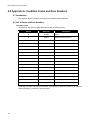
4.0 Appendix A: Condition Codes and Zone Numbers ....................................................... 46
4.1 Introduction ................................................................................................................... 46
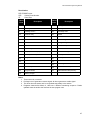
4.2 List of Codes and Zone Numbers ................................................................................. 46
5.0 Appendix B: Stand-by Battery Calculation .................................................................... 52
6.0 Appendix C: Service Terminal ........................................................................................ 53
6.1 General ......................................................................................................................... 53
6.2 Control Unit ................................................................................................................... 53
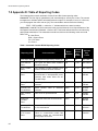
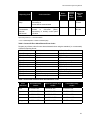
7.0 Appendix D: Table of Reporting Codes ......................................................................... 60
i
MR-2100/2200 Programming Manual
List of Figures
Figure 1: Typical Network Layout ........................................................................................ 1
Figure 2: Single Network Break .......................................................................................... 3
Figure 3: Panel Removed from Network ............................................................................. 4
Figure 4: Four Wire Device Wiring (Typical) ....................................................................... 7
Figure 5: Modul-R System Window ..................................................................................... 9
Figure 6: Switches Window ................................................................................................. 13
Figure 7: Groups Window ................................................................................................... 14
Figure 8: Panel Window ...................................................................................................... 16
Figure 11: Panel Outputs .................................................................................................... 19
Figure 12: Options Dialog ................................................................................................... 21
Figure 13: Default Key Assignments ................................................................................... 23
Figure 14: Dialer Settings .................................................................................................... 25
Figure 14: Dialer Configuration 1 ........................................................................................ 26
Figure 15: Dialer Configuration 2 ........................................................................................ 27
Figure 16: Call Directions .................................................................................................... 28
Figure 17: Zone Data .......................................................................................................... 29
Figure 18: Dialer Maintenance and Common Reporting Codes ......................................... 29
Figure 19: Circuits Window ................................................................................................. 30
Figure 20: Devices Window ................................................................................................ 30
Figure 22: Copy Window ..................................................................................................... 34
Figure 23: Internal Circuits Window .................................................................................... 35
Figure 24: Relate Window ................................................................................................... 36
Figure 25: Program Menu ................................................................................................... 39
Figure 26: Selector Screen ................................................................................................. 40
List of Tables
Table 1: Automatic Contact ID/SIA Reporting Codes ......................................................... 60
Table 2: Contact ID Zone Alarm/Restore Event Codes ...................................................... 61
Table 3: SIA Format Automatic Zone Alarm/Restore Codes .............................................. 61
iii
MR-2100/2200 Programming Manual
1.0 Operation and Programming Concepts
1.1 Introduction
This chapter provides an overview of the MR-2100/2200’s (hereafter called the MR-2200) features
and supported devices.
1.2 General Information
Warnings: Before Programming
1. All applicable codes and standards should be considered when programming the Control
Unit.
2. The Control Unit continues to monitor input circuits and devices and acts according to the
current program settings if an alarm is received while it is being programmed.
3. Loading a new database erases the current database before loading the new database. If
the new database is not loaded after the erasure, the panel will not operate.
4. The database internal revision number included must match the number required by the
MR2 program, otherwise a Database Mismatch trouble condition is generated. This
condition disables the panel until a correct MR2 program is loaded.
5. The database must be completely loaded for it to be considered valid. The program keeps
track if the last database load was valid/complete or not. An invalid database load disables
the panel until a valid database load is done.
Downloadable Database
The panel uses a downloaded database for input circuit programming. This database includes the
addressable devices on-line, and the Zone LEDs, Bells, Functions Relays and Control Modules
activated by addressable devices. This database is created and downloaded from an IBM
compatible computer using the Modul-R Human Interface (MHI) program. Refer to the Modul-R
Human Interface User Guide for instructions on downloading the database.
Note: All communications are stopped during the database load. This causes a trouble to be recorded by those
units that are normally communicating with the panel.
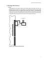
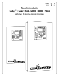
1.3 Networks
General
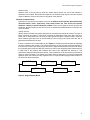
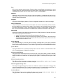
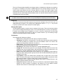
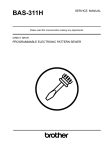
The MR-2200 can be incorporated into a network including other MR-2900 panels and MR-2944
annunciators. Though up to 254 panels and annunciators can be supported by the network, such a
network would probably be too large to properly maintain. The network can be setup for single
building or multiple building operation.
MR-2200
ID #1
Com2
MR-2944
ID #3
MR-2900
ID #2
Com1
Com2
MR-2200
ID #5
Com1
Com2
Com2
Com1
Com1
MR-2944
ID #4
Com1
Com2
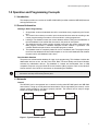
Figure 1: Typical Network Layout
1
MR-2100/2200 Programming Manual
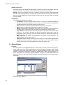
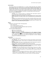
The basic layout of the network is a single loop (see Figure 1). Each panel and annunciator has a
unique ID. There is no requirement that the IDs be sequential or that they start with 1. The master
panel can be any fire panel in the network. The panels work in a peer-to-peer fashion. This means
that each panel is responsible for the programming of the inputs connected to it. The master panel
does not control the network, but it is the central location for network information. Information is
exchanged over the network via two basic means: a) specific frames, which are from one panel to
another, and b) broadcast frames, which are from one panel to all others.
Note: 1. For correct operation of the network, all panels and annunciators need to be loaded with the
same version of operating programs and with the same database. If changes are made to the
database, it is necessary that ALL panels and annunciators be reloaded.
2.When panels and annunciators are first installed, the panel ID must be entered into it before
loading the database.
The special functions of master panel are:
a)
b)
c)
synchronize the clocks on the network by broadcasting the date and time at 3:30am every
day; this means that only the master panel of a network requires that its clock be calibrated;
maintain a network alarm list that includes all alarms, supervisory and trouble conditions
induced on any panel on the network;
transmit all signals from the network to a monitoring location.
Feature Operation
The following are the various types of frames that are sent on the network.
Commands & Restores
These specific frames are sent when a device in alarm requires operation of outputs at another
unit. These commands are for the bells, relays, control modules, device messages and LEDs.
When the device itself restores, the restore commands are sent right away so that the other panels
know that they can be reset. Anything operated stays latched until the Reset key is pressed.
Hotkey and Hotkey LED Operation
If Hotkey routing is on a panel, it will send Ack, Reset, Sig Sil and Second Stage Inhibit to the other
panels as specific frames.
If a panel’s function keys are sent to other panels, those panels will send commands to the panel
to have it turn on and off the hot key LEDs. This is so that there is indication that the key function
has become available. This will cause the LEDs to continue flashing after the key is pressed until
the frame is received to turn off the LED.
Time/Date Change
This broadcast frame is sent by a panel or annunciator if the time or date is changed. The master
panel also sends both a date and time change frame at 3:30am every day to synchronize all the
clocks in the network.
Manual Switch Operation
If the state of any of the 16 software switches is changed manually at any panel, this change is
broadcast to all other panels. The software switches are a system resource.
Network Reboot
If a Network Reboot command is initiated at a panel, it is broadcast normally and then the panel
reboots itself. Upon receiving the Network Reboot command, a panel passes the command on to
the next panel and then reboots itself. This has the affect of causing all the panels to reboot
simultaneously.
2
MR-2100/2200 Programming Manual
Network Verify
Network Verify is the process by which the master panel queries the rest of the network to
determine on-line status. Each panel will respond to the network verify request. The user can also
request a Network Verify at any time from any panel in the network.
Network Communications
Information is sent across the network in frames. In addition to the operator generated frames
described above, alarm, supervisory, and trouble frames are sent across the network
whenever a device or panel indicates a problem. There are two types of frames: specific and
broadcast. Specific frames are sent from one unit to another. Broadcast frames are sent from one
unit to all others.
Specific Frames
Specific frames deal with information generated at one panel and required at another. This type of
frame is passed from panel to panel until it reaches its destination. Each panel has a list as to
which port to send frames from to reach all other panels through the fewest number of panels.
Since networks generally have all communications links running at the same baud rate, this is
generally the shortest time as well.
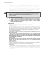
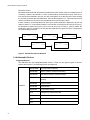
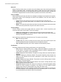
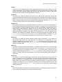
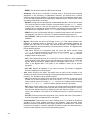
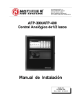
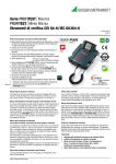
If there is a break in the communications (see Figure 2), the panel that cannot pass the message
on sends it back the way it came. This causes the frame to go the long way around the network. If
there are two breaks in the network loop, the frame is again reversed at the second break. When
the originating panel receives it after the second turn around, the originating panel realizes there is
a major fault in the network and considers the frame to be orphaned and destroys it. This
generates a Network Reboot Required trouble. This is passed on to all other panels (or at least as
many as can be reached). The reason the orphan frame is destroyed is to prevent unexpected
operation when the network is finally repaired, such as a panel starts ringing its bells because of
an alarm from the previous day.
M R 2 2 0 0
ID # 1
C O M 2
M R 2 9 4 4
ID # 3
M R 2 9 0 0
ID # 2
C O M 1
C O M 2
M R 2 2 0 0
ID # 5
C O M 1
C O M 2
C O M 1
C O M 1
M R 2 9 4 4
ID # 4
C O M 2
C O M 1
C O M 2
Figure 2: Single Network Break
3
MR-2100/2200 Programming Manual
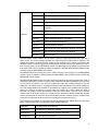
Broadcast Frames
Broadcast frames deal with information that affects the entire network. When a broadcast frame is
created by a panel or annunciator, it is sent out both network communications ports. Each unit in
turn receives the broadcast in one port, act upon it and pass it on out the other port. Upon reaching
the unit that generated the broadcast frame, that unit then disposes of it. This means that under
normal circumstances, all units receive a broadcast twice and act upon it twice.
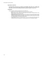
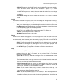
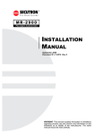
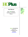
If there is break in a communications link (see Figure 2) the broadcast is disposed of by the unit
unable to pass it on. In the situation where a unit has been removed from the loop (see Figure 3),
the broadcast is passed only from com2 to com1 at the jump. In Figure 3, panel 5 passes the
broadcast to panel 3, but panel 3 will not pass the broadcast on to panel 5 since it is supposed to
be communicating to panel 4.
M R 2200
ID # 1
M R 2944
ID # 3
M R 2900
ID # 2
C O M 2
C O M 1
C O M 2
C O M 1
M R 2200
ID # 5
C O M 1
C O M 2
C O M 1
M R 2944
ID # 4
C O M 2
C O M 1
C O M 2
Figure 3: Panel Removed from Network
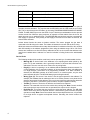
1.4 Addressable Devices
Supported Devices
The MR-2200 can use analog/addressable devices. There are two general types of devices:
sensors and modules. The following devices are supported:
Modules
4
MRI-M500DM
Dual Input Monitor Module
MRI-M500M
Monitor module, Classes A/B initiating
MRI-M501M
Mini Monitor module, Class B initiating
MRI-M502M
Monitor Module for 2- wire smoke detectors Classes A/B
initiating
MRI-M500S
Control module
MRI-M500R
Relay Module
MRI-M500X
Fault isolator module
IM-10
Intelligent Input Monitor Module
CZ-6
Zone Interface Module
CR-6
Control Module Relay
SC-6
Supervised Control Module
MR-2100/2200 Programming Manual
Sensors
MRI-1251
Ionization type smoke detector, low profile
MRI-1551
Ionization type smoke detector
MRI-2251
Photoelectric type smoke detector, low profile
MRI-2551
Photoelectric type smoke detector
MRI-2251T
Photoelectric type smoke detector c/w heat detector,
low profile
MRI-2551TH
Photoelectric type smoke detector c/w heat detector
MRI-2251TMB
Acclimate Photo-Thermal Detector
MRI-5251
Fixed temperature detector, low profile
MRI-5251H
Fixed high temperature detector
MRI-5551
Fixed temperature detector
MRI-5251R
Rate of Rise and fixed temperature detector, low profile
MRI-5551R
Rate of Rise and fixed temperature detector
MRI-7251
Pinnacle Laser
The MRI-M500S control module can be used to control a supervised output, such as a bell or
strobe circuit. The control module monitors the circuit wiring and troubles will be reported. The
module will require a separate 24 VDC supply for the controlled circuit. When programming the
database in MHI, be sure to program the control module correctly. Choose any “Control (str)” other
than “Control (relay)” for the MRI-M500S module. The MR-2400 will not operate a control module
if the supervised circuit is shorted. Also there are options in MHI that affect the MRI-M500S control
module but not the MRI-M500R relay module.
The MRI-M500R relay provides two Form C relays. Choose “Control (relay)” for the MRI-M500R
module. There are options in MHI that affect the MRI-M500R relay module that do not affect the
MRI-M500S control module.
The MRI-M500X isolator module is used to prevent wiring faults from affecting the entire circuit. It
divides the addressable circuit into sections. The isolator has separate IN and OUT wiring. A short
on one side of the isolator is not seen on or affects the other side. Isolator modules do not use
addresses. The isolator relies on a voltage threshold to determine whether it should be isolating or
not. This voltage threshold is around 6.5V. All isolators in a system are in isolated mode on system
power up. If there is an excess of current draw, the isolator will not close. When the short is
removed, the isolator module automatically closes the circuit again. The LED on the isolator
module turns on when the module is in isolated mode, otherwise it flashes periodically. System
Sensor recommends no more than 25 devices between isolator modules since the inrush current
of the devices may mimic a short condition preventing the isolator from closing.
The sensors all use bases for mounting. Besides the standard plain bases, there are also relay
bases, isolator bases and a sounder base. The available bases are:
MRI-B501
Flangeless base for all sensors
MRI-B501B
Flanged base for MRI-x551 sensors
MRI-B210LP
Flanged base for MRI-x251 sensors, low profile
MRI-B501BH
Sounder base for all sensors
5
MR-2100/2200 Programming Manual
MRI-B501BHT
Sounder base, temporal
MRI-B524BI
Isolator base for MRI-x551 sensors
MRI-B224BI
Isolator base for MRI-x251 sensors, low profile
MRI-B524RB
Relay base for MRI-x551 sensors
MRI-B224RB
Relay base for MRx251 sensors, low profile
The sensor LED activates the relay and sounder bases. When this LED stays on for more than 10
seconds, the base activates. This requires that the MR-2200 have the LED mode set to FLASH/
ON. This is done through the LCD Menu by choosing PROGRAM/ADDRESSABLE/LED MODE/
FLASH. The MR-2200 only turns on the LEDs of up to 5 devices per addressable circuit to prevent
excess current flow. While the panel continues to respond to further alarms from the circuit, the
panel does not turn on additional LEDs. The MRI-B501BH sounder base requires a separate 24
VDC supply for operation. If the polarity of this supply is reversed for more than 10 seconds, the
sounder base activates.
Isolator bases function the same as isolator modules. The sensor plugged into the base is
connected to the IN wiring to the base. The isolator is between the sensor and the OUT wiring.
While both sensors and modules have rotary dials that allow for addresses from 00 to 99, modules
add 100 internally to the address programmed, thus using the address range 100 to 199. Since
sensors and modules come from the factory addressed as 00, we do not allow that address to be
used for an installed device. Address 0 is used for indication of wiring faults on the addressable
circuit.
Device Faults
The following troubles (with condition code letter) can be reported by or for addressable devices:
•
•
•
•
•
6
Missing (M): A device listed in the database is not reporting back when polled by the
panel. For a new installation, this is generally indicative of devices that have been misaddressed. This error can also occur if there are any wiring faults.
Illegal (I): A device is reporting in on an address that the database shows as unused. For
a new installation, this is generally indicative of devices that have been mis-addressed.
For illegal sensors, since there is no programming available, if an alarm condition is
detected, the MR-2200 operates all its bell circuits. In a network system, only the local
panel activates its bells. The MR-2200 always ignores illegal modules.
Wrong Type (U): This occurs if the device is not the type expected for the address. For
example, the database lists an address to have a ion smoke detector, but a photo smoke
detector has reported for the address. This error is also used if the panel cannot determine
the type of the device. If the device goes into alarm, the panel operates normally.
Trouble (T): Sensors: The device is defective and needs to be replaced.
Modules: The extended circuit from the module has a wiring fault. Note: Control modules
that supervise their output circuits are not operated if the output circuit is shorted.
Duplicate (D): This means that two devices are using the same address. The MR-2200
does a check every hour for duplicate devices. If either device goes into alarm, the panel
operates normally. Note: Due to the method used to detect duplicate devices, it is possible
for a single device to appear as duplicate devices. Generally, the device needs to be
replaced.
MR-2100/2200 Programming Manual
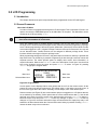
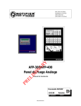
1.5 Resetting 4-Wire Detectors
General
4-wire detectors can be reset by using one of the function relays on the panel. The relay is not
programmed for any use, that is, it is unassigned. The next requirement is that a non-zero duration
be programmed for it (See “2.7 Outputs Dialog” on page 19) A duration of zero disables this
function. Once this is done, wire the power for the device as shown in Figure 4. A third party power
supply (must be UL/ULC-listed compatible power supply suitable for fire applications) can be used
instead of the Aux Power as shown. Whenever the System Reset operator key is pressed when
neither LED is flashing, causes the relay to operate for the duration programmed.
To Monitor Module
Input
AUX
+
AUX
+
COM
RLY 4
4 Wire Device
+
NC
NO
COM
RLY 3
NC
NO
COM
RLY 2
NC
NO
COM
RLY 1
NC
NO
Figure 4: Four Wire Device Wiring (Typical)
7
MR-2100/2200 Programming Manual
2.0 Editing MHI Databases
2.1 Introduction
This chapter describes the windows used to program the system.
2.2 General Comments
Overview
The editing of a system is done through a series of input windows. Editing starts with the System
Level and progresses to the Panel Level, then to the Input Level, and finally to the Relate Level.
The Main Menu and option speed keys are not available while editing/viewing the system. While
editing is being done, the word OPEN is displayed in the Status Bar. This is to remind the user that
the system database is open and that the computer should not be turned off. If the computer is
turned off while the database is open, it may become corrupted.
If the current database has been previously verified and you select Edit, a requester is displayed
confirming your request to edit the database. If No is chosen, then the database is displayed in
View mode. Editing the database changes the database to a non-verified state and changes the
Last Edit Date.
Prior to an editing session, the database is automatically backed up. This back up copy has the
same name as the original database, but incorporates a .BAK extension. If a database becomes
corrupted, delete it and rename its .BAK backup file to have a .DBA extension. This restores the
database to the state prior to the last editing session.
Note: When upgrading from a version 17 (or earlier) system, a number of items that were programmed
at the panel are now included in the database. See the file UPGRADE.TXT for a complete
description of these changes.
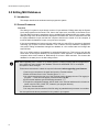
Follow these instructions to obtain the required information before upgrading your firmware:
1.Connect your computer to the panel and open the Terminal window
2.Select the Printer screen in the Terminal: press 14<Tab>
3.You should note that the title bar of the Terminal window displays the text "File logging in
progress...". If this does not appear, press the button Log On.
4.In the terminal window, type the following command: 99?
5.The panel's configuration settings will be listed in the Terminal window and it will also be
saved in the file: LOG_CONT.TXT, located in your program directory
6.Close the Terminal window
7.You may now view the contents of the file using any standard word processor or text editor
You must perform the above procedure for ALL panels in your system
8
MR-2100/2200 Programming Manual
Network-Capable Panel Types
The following panels can be used in a network configuration.
•
•
•
•
MR-2100 Fire Panel: The MR-2100 has one (Class A or B) SLCs and two (expandable to
eight) NACs. The NACs can be programmed to be used as either bells or strobe type
circuits. The MR-2614 Annunciator can be attached to the MR-2100 panel. It is considered
an extension of the panel by MHI and does not change how the panel interfaces with other
annunciators.
MR-2200 Fire Panel: The MR-2200 has two (Class A or B) SLCs and two (expandable to
eight) NACs. The NACs can be programmed to be used as either bells or strobe type
circuits. The MR-2614 Annunciator can be attached to the MR-2200 panel. It is considered
an extension of the panel by MHI and does not change how the panel interfaces with other
annunciators.
MR-2900 (mb2931) Fire Panel: This is an MR-2900 Control Panel using the MR-2931
motherboard. This panel accepts all input circuit modules and has four Class A or eight
Class B power-reversing output circuits. These output circuits can be programmed to be
used as either bells or releaser type circuits. This is the standard board for the MR-2900.
These panels can be used in a network configuration.
MR-2944 Annunciator: It includes the memory required to have a database loaded into it.
This allows for less information to be sent on the network. An optional 4x20 LCD can be
included. This annunciator has two communications ports. This allows the annunciator to
reside in the network loop. It uses the MR-2910 Network Board.
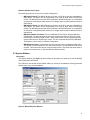
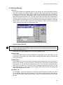
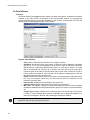
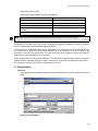
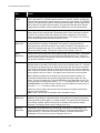
2.3 System Window
Description
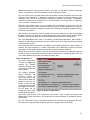
The System Window (see Figure 5) allows editing of all system level options, as well as detailing
other system wide information.
The Title Bar of the window shows whether editing or viewing of the database is being preformed
and the name of the current database.
Figure 5: Modul-R System Window
9
MR-2100/2200 Programming Manual
The text in the top left corner provides information about the database. The top line gives the date
and time the database was last edited. The next line states whether the current contents have
been verified or not; and whether the database has been compressed or not.
The options Bell System, Subsequent Alarm, Resound, Evac and Waterflow all affect how the
notification appliance circuits (NAC), hereafter referred to as bells, react to alarm conditions.
Bell System
Bell System is a drop down list for selecting how the bells and strobes will operate. This sets the
base operation for the entire network. If coded bells are required, the bell codes are defined for
each input individually. The following options are available:
•
•
•
•
Alert: A First Stage alarm activates the selected bells in Alert mode. If the Signal Silence
or Second Stage Inhibit Hot Key is not pressed before the [No Acknowledge] Second
Stage Inhibit timeout, the panel will progress to Second Stage. Second stage will activate
all bells in Evacuation mode.
Evac: A First Stage alarm will activate selected bells in Evacuation mode. Second Stage
will activate all bells in Evacuation mode. There is no timeout from First to Second Stage.
Alert/Evac: A First Stage alarm activates the selected bells in Evacuation mode and all
other bells on the panel in Alert mode. If the Signal Silence or Second Stage Inhibit Hot
Key is not pressed before the [No Acknowledge] Second Stage Inhibit timeout, the system
will progress to Second Stage. Second Stage will activate all bells in Evacuation mode.
Staged: The 1st alarm will activate selected bells in Alert mode. If the Signal Silence or
Second Stage Inhibit Hot Key is not pressed before the [No Acknowledge] Second Stage
Inhibit timeout, the selected bells are switched to Evacuation mode and the next bells, i.e.
the ones with the next higher number, are activated in Alert mode. This sequence is
repeated until all bells are in Evacuation mode. When the highest numbered bell circuit
switches to Evacuation mode, all bell and strobe circuits on the panel will be turned on in
Evacuation mode. For example, if the alarm activates Bells 1 and 4, after the NAK timeout,
Bells 1 and 4 are switched to Evacuation mode and Bells 2 and 5 are set to Alert mode. A
2nd alarm will activate all bells in Evacuation mode.
Note: 1.Bells must be assigned consecutive bells circuits with no Releasers assigned in
between Bells. For example: circuits 1, 2, 3, 4 can be assigned as Bells but not
circuits 1, 2, 4, 5 with circuit 3 a Releaser.
2.Control modules cannot be programmed as bell or strobe if the Staged Bell
system is used.
Subsequent Alarm
Subsequent Alarm controls how Alert, Evac and Alert/Evac type bell systems behave when a new
alarm is received while one is still active. 1st Stage has the panel repeat the First Stage operation.
2nd Stage has the panel go immediately to Second Stage operation.
Resound
Resound controls how the panel handles the automatic resounding of silence bells when a new
alarm is received. There are two modes:
•
•
10
Local: Each panel resounds only its own silenced bells when a new alarm is received.
This would be used when panels in a network are in different buildings, such as a campus.
Global: All panels in a network resound silenced bells when a new alarm condition is
received on any panel in the network. This is used when the panels are all in the same
building, such as a large plant.
MR-2100/2200 Programming Manual
Evac
Evac controls whether the bell system Evacuation Mode sounds Steady (continuously) or uses a
Temporal pattern as specified in ANSI S3.41 and ISO 8201 Audible Emergency Evacuation Signal.
The pattern used ½s On, ½s Off, ½s On, ½s Off, ½s On, 1½s Off repeated.
Waterflow
Waterflow controls if bells can be silenced if they are started by a waterflow type input. If NonSilenceable is chosen, bell circuits activated due to a waterflow input cannot be silenced until the
waterflow device has restored.
Language
Language chooses English (default), French or Hungarian characters to be used in messages.
Alarm List Sequence
Alarm List Sequence controls which end of the Alarm List is shown automatically. If First is chosen,
the first (oldest) item in the alarm list is shown. If Last is chosen, the last (newest) item in the alarm
list is shown. Regardless of order, alarms always take precedence in being shown. Another way to
think of it is that First shows where the fire started while Last shows where the fire has gotten to.
Disconnects
Disconnects controls which panels the Signal Disconnect, Relay Disconnect, Releaser Disconnect
and Common Disconnect hot keys affect.
•
•
Local: The Disconnect hot keys affect only the panel they are on.
Global: The Disconnect hot keys affect all the panels in the network. This means that if
any Disconnect key is pressed on a panel, all other panels in the system take on the state
of that Disconnect, either on or off.
System Message
The System Message is a text entry box for defining a message that is 3 lines by 20 characters
that is used to identify the system. This message is printed at the top of printouts and shown on
some service terminal screens, but it is not used in any LCD except in STATUS/IDENTIFICATION.
System Banner
The System Banner is a 20 character message that is used as a banner for the Main Menu of the
LCD. The default banner is “Modul-R by Secutron”.
Enforce Local LED Rules
The Enforce Local LED Rules check box forces an LED on an input's panel be related. Normally
an LED anywhere in the system is all that is required. Note: The common LEDs of any panel are
based upon the zone LEDs that are displayed by the panel, not based upon the inputs to the
panel.
Enforce Group Association
The Enforce Group Association checking check box enables MHI to check to see if a group
association has been included in the relates of inputs.
Observe Daylight Savings Time
The Observe Daylight Savings Time check box enables or disables the automatic changing of the
clock for Daylight Savings Time. If enable, the system moves 1 hour ahead the second Sunday of
March and fall back 1 hour the first Sunday of November (North American dates).
Pre-Alarm Buzzer
The Pre-Alarm Buzzer, when enabled, will cause a tone to sound when a smoke detector is
verifying its alarm. The tone is a triple beep repeated every second.
11
MR-2100/2200 Programming Manual
Master ID
Master ID defines which panel in a network acts as the Master panel. Only control panels may be
chosen as the Master panel. The Master panel retains an alarm list for the entire network and
synchronizes the date and time on all panels and annunciators at 3:30am everyday. (The alarm list
functionality is programmable for several modes of operation. See below for more detail.)
Alarm List Mode
Alarm List Mode sets the way the Alarm List messages are displayed on fire panels in the system.
Annunciators always receive messages as marked in the database. There are three modes of
displaying messages:
•
•
•
Local: Each fire panel shows only Alarm List entries that are for that panel only.
Global: Each fire panel shows Alarm List entries for itself and all other panels and
annunciators.
Master: The master fire panel shows the Alarm List entries for all panels and annunciators
while all other fire panels show only their own Alarm List entries.
Common Relays
Common Relays controls what signals affect the common alarm, common supervisory and
common trouble relays of each panel. The are two settings:
•
•
Local: The common relays of a panel follow the events of events on that panel only.
follow Alarm List Mode: The common relays of a panel react to both events of the panel
and any events listed in its Alarm List.
Non-Latch Mode controls if the panel will auto store. The options are as follows
•
More: Everything Latched
•
Trouble only: Only trouble conditions will auto restore; Note some troubles require user
intervention before the panel can determine if the condition be restored
•
Supv and Trbl: Supervisory and Trouble conditions will automatically restore.
Pushbuttons
The System Window has the following push buttons on the right hand side:
•
•
•
•
•
•
•
12
Exit: Closes the System Window and, if editing, causes the database to be saved. After
an edit session, a requester asks if the database should be Verified. A database has to
verify without errors before it can be downloaded.
Panels: Displays the Panel Window. If no panel is currently defined, the Add Panel Box is
displayed.
Switches: Displays the Switches Window. This window determines which devices are
attached to the switches and the timers associated to each switch. See section 2.4
Switches Window.
Groups: Displays the Groups Window. This window is used to define groups of relates.
See section 2.5 Groups Window.
Map: Displays and/or updates the Map Window. See section 2.8 Map Window of the
Modul-R Human Interface User Guide.
Verify List: Displays the Verify List. If there is no Verify List, a requester will appear asking
whether you wish to perform a verification. See section 2.6.5 of the Modul-R Human
Interface User Guide for a full description of the Verify List and its uses.
Settings: Defines the Verify warnings to disable and/or errors to reduce to warnings for
the current database. Not all warnings/errors can be disabled/reduced. The use of this is
not recommended, but provided for special circumstances.
MR-2100/2200 Programming Manual
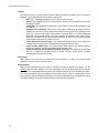
2.4 Switches Window
Overview
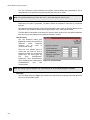
The Switches Window (see Figure 6) allows for the setting of the On/Off (Day/Night) switches.
There are 16 system wide switches available. All panels in the network keep track of their portion
of the devices related to each switch. Relays, LEDs and control modules follow the On/Off state of
the switch they are related to. Addressable sensors use Day sensitivity while the switch is on and
Night sensitivity while the switch is off. The timers can be used to have the switch change state at
set times each day. Switches can be operated manually at the panel whether they have timers or
not. If the Switch is associated to a Hot Key, the Hot Key then operates the switches, causing the
related LEDs, relays and control modules to react. Changing a switch manually at one panel
causes all panels in the network to change switch state.
Figure 6: Switches Window
Note: 1. Addressable detectors can only be related to a single switch each.
2. Relays, LEDs and control modules controlled by more than one switch stay on as long as any
switch operating them is on.
The title bar of the window always lists the currently highlighted switch.
Switches Table
The Switches Table shows all 16 possible switches and highlights the current one. Select any one
to make it the current switch. List entries show the message RELATES FOUND for switches that
have related devices.
HH:MM (Timer)
The HH:MM (Timer) entries control the times that the switch changes state. An even number of
times must be entered, ie. each on must have a corresponding off. All times are entered using 24
hour notation, e.g.: one minute after midnight=0:01, noon=12:00, 3 PM=15:00, 4 AM=4:00, etc. A
time of 0:00 is considered as not used. If an action at midnight is desired set the time to 0:01, one
minute after midnight; or 23:59, a minute before midnight. MHI sorts the times into ascending order
after the Switches Window is closed.
Start Mode - On
The Start Mode - On check box determines if the first time listed should turn the switch On or Off. If
it is not checked, the first time turns the switch off. If it is checked, the first time turns the switch on.
The on and off indication beside each time entry changes to reflect what each time in the sorted
list does.
13
MR-2100/2200 Programming Manual
Use Switch as Custom Hot Key
Use switch as Custom Hot Key allows the switch to be manually controlled by the Hot Keys. A hot
key can be assigned to turn the switch on and another to turn it off. These keys are marked as HK
in the Switches Table.
Description
Description is a 20 character message that describes the Switch usage. This is useful in that the
switch now has a description of its usage that is easier to understand when assigning Switches to
Hot Keys.
Pushbuttons
There are five push buttons on the right side:
•
•
•
•
•
Exit: Close the Switches Window and return to the System Window. If there are any
invalid times entered (ie greater than 23:59), MHI requests corrections.
Reset: This removes all relates and all times for the currently highlighted switch.
Relate: Shows the Relate Window. Items marked *on* are operated/controlled by the
switch.
Map: Displays and/or updates the Map Window. See section 2.8 Map Window of the
Modul-R Human Interface User Guide.
Verify List: Displays the Verify List. If there is no Verify List, a requester will appear asking
whether you wish to perform a verification. See section 2.6.5 of the Modul-R Human
Interface User Guide for a full description of the Verify List and its uses.
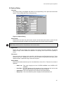
2.5 Groups Window
Overview
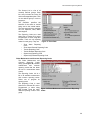
The Groups Window (see Figure 7) is used for creating and editing the Groups of relates. The
Title Bar shows the current group.
This dialog allows you to setup "Groups" which are composed of a text description/message and
relates. Groups are a method of establishing zone representations. A zone representation may
include a message and/or a group of Relates. Inputs (ie. circuits and/or devices) may relate to a
Group or number of Groups and thus acquire all Relates that are referenced by them. Inputs can
also separately adopt the Group message. Making a change to a Group affects all inputs (circuits
and devices) related to the Group. This is a very powerful feature that can significantly speed up
the creation of medium to large size systems as well as simplify changes. Forethought should be
placed in defining appropriate Groups. Up to 250 groups may be defined.
Figure 7: Groups Window
14
MR-2100/2200 Programming Manual
The use of Groups greatly simplifies the changes made to a database as changes are needed by
the system. For example, if new door is installed that has to be unlocked during a fire alarm, the
control module that unlocks the door is simply added to a Group. This single change is then
automatically picked up by any inputs that are related to the Group. Since this number could be
hundreds, the use of the Groups makes databases easier to maintain and decreases the likelihood
of mistakes when items are added.
Note: Though any relationship can be selected for inclusion into a group, an input that references the group must
be able to accommodate the group’s relates. It may be advantageous to separate groups in these cases.
Group List
The Group List shows all the defined groups along with their message (if any) and if there are any
relates defined for the group. The current group is highlighted. Use the <Backspace> key in order
to quickly re-position the current selection to another group.
Message Description
The Message/Description is used to enter a message for the group. This set of text-boxes allows
you to enter a message describing the Group. You are allowed space for 3 lines by 20 characters.
If desired, this message may be adopted by a circuit or device by checking the Use Grp Msg
check-box and specifying this Group ID. This is a powerful feature if you are defining a large
number of inputs that require the same message.
Pushbuttons
The following push buttons are defined:
•
•
•
•
•
•
•
•
•
Exit: Close the Groups Window and return to the previous window.
Add Group: This defines a new group ID. The new group can have any number between
1 and 250. By default, the number is the next one available. There is no need for the
groups to be sequentially numbered or to start at 1.
Delete Group: This removes the group from the list. You are asked if you want to have
references to the group automatically removed.
Reset Group: This removes all relates for the currently highlighted group.
Change ID: This allows the group ID to be changed. This may need to be done if two
databases are being merged together. MHI automatically changes all references to use
the new ID. A gauge is displayed to show the progress of the change.
Relate: Shows the Relate Window. Items marked *on* are operated by inputs related to
the group. When relating inputs to groups, be sure that all relates defined by the group are
allowable for the input.
Copy Relates: Copies the relates and/or message from an input point to the current
group. The values of the panel, circuit and device are required. Most conventional circuits
use a device number of 0 (zero). Press Copy to copy the information.
Map: Displays and/or updates the Map Window. See section 2.8 Map Window of the
Modul-R Human Interface User Guide.
Verify List: Displays the Verify List. If there is no Verify List, a requester will appear asking
whether you wish to perform a verification. See section 2.6.5 of the Modul-R Human
Interface User Guide for a full description of the Verify List and its uses.
15
MR-2100/2200 Programming Manual
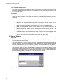
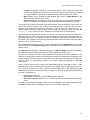
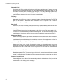
2.6 Panel Window
Overview
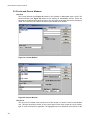
The Panel Window (see Figure 8) allows editing of all panel level options. It defines the hardware
mounted in the panel and the functionality of the programmable outputs. The programming
controls provided change to reflect the capabilities of the currently selected panel. The Title Bar
describes the currently highlighted panel or annunciator.
Figure 8: Panel Window
•
•
•
•
•
•
•
Exit: Close the Panel Window and return to the System Window.
Add Panel: Add another panel to the system. A dialog box will be displayed. The default
options are to use the next available panel ID and to select an MR-2100, MR-2200,
MR-2900 panel or MR-2944, MR-2934 annunciator. You will also be asked if you want
MHI to automatically set the Next ID. If allowed, this panel will have the next higher
numbered panel as its Next ID and the panel with the next lower number will be set to
have this panel as its Next ID. If the new panel is the highest numbered panel, it will use
the lowest numbered panel as its Next ID.
Delete: Remove the current panel from the system. All programming for that panel will be
lost. Any of the panel's outputs that are referenced will become invalid and will be
removed by the next verify.
Input Circuits: Display the Circuits Window. See section 2.6
Internal Circuits: Display the Internal Circuit Window. See section 2.7.
More Info: This displays a dialog box listing basic information about the panel including
the date the database was last downloaded into a panel, the number of times downloaded,
etc.
Change Type: Displays a dialog box to change the type of the current panel. This makes
it easier to correct mistakes when creating a database and to update the database if a
panel type is changed in the field. Only certain type changes are allowed.
Note: Changing the panel type can have far reaching effects on a system. Any information that is no
longer valid with the new panel type will be lost
16
MR-2100/2200 Programming Manual
•
•
•
Change ID: Displays a dialog box for changing the ID of the current panel. MHI will
automatically change all references to use the new ID. This process could take a long time
for a large database. A gauge will be displayed to show the progress of the change.
Map: Displays and/or updates the Map Window. See section 2.8 Map Window of the
Modul-R Human Interface User Guide.
Verify List: Displays the Verify List. If there is no Verify List, you will be given the option to
perform a verification. See section 2.6.5 of the Modul-R Human Interface User Guide.
The Panel List is located in the top left corner of the window. It lists all the panels, both Control and
Annunciator, that are defined in the system. The highlighted entry in the List is the one that is
currently being edited. Its description is also shown in the title bar of the Panel Window. If a
different panel is selected, all the controls in the window will change to reflect this. Use the
<Backspace> key in order to quickly re-position the current selection to another panel.
The Message is located below the Panel List. This is a 3 line by 20 character message that is
associated with the Panel. This message will be displayed in Alarm Lists with signals that are
generated by this panel. It will also be included in any print-outs generated by the Master Panel of
the system. This message should include enough information that it will identify the panel and its
location to fire or service personnel.
The Outputs area lists the function of the outputs of the panel. Use the Outputs Button to show the
Outputs Dialog (see the Outputs Dialog section) which allows for the programming of the Outputs
and the relays.
The Options button displays the Options Dialog (see the Options Dialog section). This allows for
the programming of the various panel options, such as Hot Keys, bell timers, etc.
The Next ID is located to the left of the push buttons at the top of the Panel Window. It is not
displayed for single panel systems. It is used to define the ID of the next panel in the network loop.
Specify the panel ID of the panel to be connected to the COM 1 terminals of the current panel. See
Links for notes on programming systems that contain single-port MR-2934 or MR-2944
Annunciators.
Links is used to enter the IDs of single port annunciators that are connected to COM 1 of the
MR-2100 panel. These annunciators do not reside in the network loop, but are branches off of it.
Port 3 sets the purpose of the Port 3 general communications port. If the operating program
loaded does not support the selected setting, a wrong port 3 program trouble will be generated by
the panel. The options are:
•
•
•
none: Port 3 is not used.
PC Connect: Sets Port 3 to use the GRID program interface.
Voice Evac. System: Sets Port 3 to communicate with the MV-2700 voice evacuation
panel.
Local Ann. LED Cnt sets the number of LED zones available either on the front of the panel using
the MRDL modules and/or and MR-2614 annunciators connected to the panel.
17
MR-2100/2200 Programming Manual
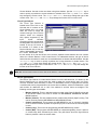
The IDs Supervised button displays all possible IDs of the MR2614 and MR-2644 annunciators (see Figure 9) as well as the
MR-2801B-MR and MRDL. Check the IDs that will be connected
to the system. When the MRDL is enabled, a button will appear
next to that option called Dialer Settings (see the section on
Dialer Options for a description of the dialer options).
Hot Key Routing is a set of radio buttons for setting the other
panels or annunciators to be controlled by the current panel. To
have no other panels affected by the current panel, mark Local.
To have the current panel affect all other panels on the network,
mark Global. To choose only some panels, mark Custom. A text
entry box entitled route panel ids is then displayed. Enter the
panel IDs to be controlled separated by commas, e.g. “2, 3, 4".
Each ID listed will receive Hot Key commands from the current
panel whenever its Hot Keys are pressed.
Figure 9: IDs Supervised
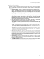
Annunciators have the
following unique controls
for
programming
(see
Figure 10).
The LCD check box is
located immediately left of
the buttons. It indicates
whether
or
not
the
annunciator has an alphanumeric LCD. This setting
is used by MHI only to
determine if the Message
Receive check box should
be
shown
for
the
annunciator in the Relate
Window. This value is not
sent to the annunciator.
LED Count is located
directly below the LCD
Figure 10: Annunciator Panel Window
check box. This defines the
number of LED zones the
annunciator will be using. A count of zero will disable the Hot LEDs and Common LED.
Hot LED is located directly below the LED Count drop down. This value defines the first of four
LED zones the annunciator will use for internal functions. Any of the zones can be chosen with the
requirement that there are four consecutive zones available. Entering a zone of 0 will disable the
hot key zones. These will reflect the current status of the annunciator and the panel(s) it sends
commands to.
18
MR-2100/2200 Programming Manual
Interpreting Flashing LED’s
The LEDs have the following meaning when flashing:
Zone n alarm: Acknowledge available
Zone n+2 alarm: 2nd Stage Inhibit available
Zone n supervisory: Reset available (green)
Zone n+2 supervisory Future use
Zone n trouble: Reset available (yellow)
Zone n+2 trouble Future use
Zone n+1 alarm: Signal Silence active
Zone n+3 alarm Future use
Zone n+1 supervisory: Signal Silence
available
Zone n+3 supervisory Future use
Zone n+1 trouble: 2nd Stage Inhibit active
Zone n+3 trouble Power On
Note: The Power On LED refers to the 24 VDC to the annunciator, not to any AC source.
Message Receive is a group of a radio buttons for setting which panels this annunciator will display
messages for. If all panels are chosen, every message in the system is displayed. If custom is selected,
then all messages from the listed panels will be displayed.
Common LED is located directly below the Hot LED setting. This is the LED zone the annunciator will use
for common alarm, supervisory and trouble indication. It is a summation of the zone LEDs of the
annunciator. Any LED zone may be used. The zone chosen will not be available for general annunciation.
Entering a zone of 0 will disable the common zone.
Ports is located below the Common LED setting. It is not displayed for MR-2914 Annunciators. This option
enables (double) or disables (single) the COM 1 network port. If both ports are enabled, the Next ID text
box will become available (see above for a description of Next ID).
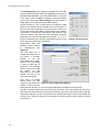
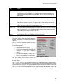
2.7 Outputs Dialog
Overview
The Outputs Dialog (see Figure 11) allows for the programming of the panel’s outputs and function
relays.
Figure 11: Panel Outputs
19
MR-2100/2200 Programming Manual
Outputs
The Outputs section is a list box that is used to select the output to program. Once the output is
selected, it is programmable for the following output types:
•
•
•
•
•
•
•
Bell: This is a standard signalling circuit. It does not sound codes.
Strobe: This signalling circuit for use with strobes. Strobe circuits cannot be silenced until
the system is reset.
Coded Bell: This signalling circuit sounds out the code for any input that operates it and
then silences.
Auxiliary Power (AuxPwr): This turns on the Output continuously to supply power for
auxiliary devices, such as annunciators. If a Duration time is given for the Auxiliary Power
circuit, the circuit is powered off for that number of seconds (from 1 to 30) when the panel
Reset key is pressed with neither of its LEDs flashing. This allows for the reset of 4 wire
detectors. A duration time of 0 prevents this operation. Auxiliary Power circuits are turned
off by the panel while it is in its power up cycle.
Follow Supervisory (follow Supv): The output sounds when there is any supervisory
condition present on the panel. Pressing Acknowledge silences the circuit.
Follow Trouble (follow Trbl): The output sounds when there is any trouble condition
present on the panel. Pressing Acknowledge silences the circuit.
Follow Supervisory and Trouble (follow Supv and Trbl): This output will sound when
there is a supervisory condition and/or a trouble condition on the panel. Pressing
Acknowledge will silence the circuit.
Relay Delay
Relay Delay is the times that the relay waits before activating. A delay of 0 causes instant
operation. This can be from 0 to 60 seconds.
Relay Duration
Relay Duration affects the time the relay is activated. For relays operated from inputs, it is the
minimum time the relay operates. The relay must stay on for this length of time before it can be
reset. This is for equipment that must remain off a length of time before it can be started up again.
If no input operates the relay, it is available for the reset of 4 wire devices. If the duration is not 0
(zero), then the relay activates for the duration time when the Reset hot key is pressed with neither
of its LEDs flashing. The duration can be from 0 to 300 seconds (5 minutes).
20
MR-2100/2200 Programming Manual
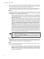
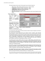
2.8 Options Dialog
Overview
The Options Dialog (see Figure 12) allows for the programming of the panel and annunciator
options. These settings affect the current panel only.
Figure 12: Options Dialog
Buzzer Mode
Buzzer Mode sets when the panel buzzer sounds. Normal causes the buzzer to sound for new
supervisory and trouble conditions. All causes the buzzer to sound for all new conditions.
Note: Always set this option to All (default) to meet current codes.
Bypass Priv
Bypass Priv. sets the privilege level required to set circuit and device bypasses, and manual
control of relays, control modules and switches. This privilege can be set to Level 2 (default) or
Level 1.
Disconnect
Disconnect sets the privilege level required for the Disconnect and Test Mode Hot Keys. These
can be set to Level 1 (default) or Level 0. If Level 0 is chosen, the Disconnect Hot Keys can be
operated without a passcode being entered into the panel.
Banner Mode
Banner Mode dictates what the top line of the Main Menu of the LCD is. There are four modes of
operation:
•
•
•
•
Status Ind.: This mode displays the lines SYSTEM NORMAL and SYSTEM OFF
NORMAL.
Panel Ban.: This mode displays the 20 characters of text entered into the text box that
appears below the drop down while this mode is selected.
System Ban.: This mode displays the text defined by the System Banner.
Equip. Desc.: This mode allows the panel to display its own identification text.
21
MR-2100/2200 Programming Manual
Remote AC Fail
The Remote AC Fail is the delay before the panel will report that it has lost AC power to a remote
monitoring location. The panel will report AC Fail locally after 60s. The panel itself will go into AC
Fail mode to conserve power immediately upon losing AC. This delay is the length of time before
the panel generates the trouble condition. This can be set from 0 to 1800 minutes (30 hours). If a
time of 0 minutes is entered, the panel will use a 10 second delay.
Fan Delay
Fan Delay sets the number of scans between the reset of each Control Module (relay) on an
addressable circuit. This is to allow for the staggered restart of fans when the system is reset. This
option can be enabled or disabled on each addressable circuit as required. It has no affect on
Control Modules (supervising).
Bell Cutoff
Bell Cutoff is the length of time the bells sound before they are automatically silenced by the panel.
A time of 0 disables this feature. The cutoff can be set from 5 to 30 minutes.
Coded Bell Speed
Coded Bell Speed sets the time interval between the bits of the codes. This speed can be 1, ¾, ½
or ¼ second. The time between digits is three times this speed. The time between rounds is seven
times this speed. Note that a minimum of three rounds of coded bells is required per NFPA 72.
Maintenance Margin
Maintenance Margin sets the gap between the maintenance threshold and the alarm threshold for
addressable sensors. If the sensor stays between these two values for the Maintenance Retard
time, the panel reports a Maintenance Alert trouble for the sensor. The margin can be set from 0 to
500, with 0 giving no warning and 500 giving the earliest warning.
Maintenance Retard
Maintenance Retard is the number of consecutive scans the addressable sensor has to stay
between the maintenance and alarm thresholds to generate the Maintenance Alert trouble. This
retard can be from 5 to 50 scans. Scan time can vary from 2.5 to 5 seconds with usual values from
3.5 to 4 seconds.
Enable Disconnect and Test Timeout
Enable Disconnect & Test Timeout enables or disables disconnect timeouts. If the timeouts are
disabled, Relay Disconnect, Disconnect, Signal Disconnect, Common Disconnect and Test Mode
must all be manually ended. If enabled, these functions are automatically ended after four hours.
Suppress Missing Signals
Suppress Missing Signals allows for the suppression of device missing signals for a loop that has
a short or ground fault condition. If enabled, the panel only reports the short or ground fault
condition, but not the missing device messages.
22
MR-2100/2200 Programming Manual
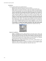
Hot Keys
Hot Keys are a set of drop down boxes that allow you to set the functions of the operator keys on
the front of the panel. There are 8 keys, each with yellow and green LED. The LEDs are used to
display function status.
SYSTEM CONTROLS
Acknowledge
Signal Silence
System Reset
User Assigned
Figure 13: Default Key Assignments
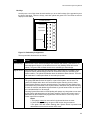
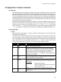
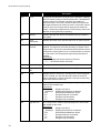
The keys and their functions are as follows:
Key
Action
Acknowledge
Silences the buzzer and acknowledges new troubles and alarms. If the buzzer is on,
Acknowledge will silence it. If the buzzer is not on, any flashing LEDs will become
steady. The green LED will flash when there is something to acknowledge.
Signal Silence
Silences the bells. The green LED will flash when Signal Silence is available. There
may be a silence inhibit before the bells can be silenced if they are activated by an
Alarm condition. The yellow LED flashes when the bells have been silenced. The bells
will reactivate if a subsequent Alarm is received by the panel.
System Reset
System Reset resets part or all of the system.
The green LED flashes when the system, or part of the system, can be reset. The
yellow LED flashes when there are conventional smoke detector circuits in alarm.
Press System Reset to reset the smoke detectors. The yellow LED also flashes if the
ground fault relay is activated. Press System Reset to deactivate the ground fault relay
to check for restores and additional ground faults. If ground faults remain, the relay will
be re-activated after 5 to 30 seconds.
Pressing System Reset with no LEDs flashing will operate any relays that are not used
by the system and deactivate any Aux Power outputs. The time they remain open is
determined by the Duration time programmed. If the Duration is 0, the relay or Aux
Power output will not operate.
Notes:
1.The system cannot be reset until all circuits and devices are reset.
2.If both LEDs are flashing, the green LED function has precedence.
3.The green LED will remain flashing after System Reset is pressed until
addressable devices have had their LEDs reset.
23
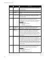
MR-2100/2200 Programming Manual
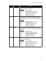
Key
Action
Second Stage
Inhibit
Prevents the automatic operation of second stage operation. This applies only to
panels with ALERT or STAGED type bell systems. For ALERT systems, pressing the
Second Stage Inhibit will prevent the panel from going into second stage. For STAGED
systems, it will prevent the system from going to the next stage. Second Stage Inhibit
has no effect on an EVAC type bell system. The green LED will flash when Second
Stage Inhibit is available, and the yellow LED will flash when it has been activated.
Fire Drill
Activates all the bell circuits, both regular and coded, in Alert mode. Press a second
time to have all bell circuits sound in Evacuation mode. Press a third time to end the
Fire Drill. The yellow LED will flash while the Fire Drill is happening. The Fire Drill
cannot be performed if the bells are already activated, or if AC power is off. The Fire
Drill is automatically ended if an alarm condition occurs.
Releaser
Disconnect
Causes the releaser circuits to ignore any new alarms. The buzzer beeps every 2
seconds while the releasers are disabled. This beeping is suppressed while a
privileged level is entered in the panel. Press again to restore normal operation. The
yellow LED will flash while active. If no releasers can be disconnected, Releaser
Disconnect will do nothing. This function can be set to Privilege Level 0 or 1.
Relay
Disconnect
Causes the function relays and control modules to ignore any new alarms. Press again
to restore normal operation. The yellow LED will flash while active. If no relays nor
control modules can be disconnected, Relay Disconnect will do nothing. This function
can be set to Privilege Level 0 or 1.
Test Mode
Places panel into test mode. Press again to return to normal mode. The yellow LED
will flash while in test mode. This function can be set to Privilege Level 0 or 1. It follows
the Disconnect privilege level (set in MHI). During test mode, the remote annunciator
zone LEDs becomes non-latching for the zone(s) under test. The common indicators,
bells, relays and releasers are not activated and no commands are sent to other units
and no signal is sent out of Port 3. Test signals can be archived or not as required.
Before beginning testing, the circuits/devices to be tested must be selected. All
unselected circuits/devices will operate normally. Be sure that the panel is in test
mode. To select circuits/devices, select PROGRAM from the Main Menu on the LCD.
The arrow keys move the cursor and the <Enter> key selects the item. Then select
ADDRESSABLE, then TEST. Enter the device circuit and address for each device to
be tested. <Clear> will return to the previous menu.
When test mode is ended, all zones and devices selected for testing automatically
return to normal operation.
Note: There is no Ground Fault isolation while Test Mode is active.
24
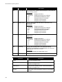
Signal
Disconnect
Disables sounding of the bells. The buzzer beeps every 2 seconds while the bells are
disabled. This beeping is suppressed while a privileged level is entered in the panel.
Press Signal Disconnect again to re-enable the bells. The yellow LED will flash while
the bells are disabled. Signal Disconnect is not available if the bells are already
activated. This function can be set to Privilege Level 0 or 1.
Common
Disconnect
Disables the municipal relays from functioning. Press again to enable relays. The
yellow LED flashes while the relays are disabled. The municipal relays affected are
programmable. If no relays are selected for disabling, Common Disconnect is
unavailable. This function can be set to Privilege Level 0 or 1.
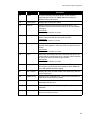
MR-2100/2200 Programming Manual
Key
Action
General
Alarm
Initiates the general evacuation sequence. All bells are activated in Evacuation mode,
selected function relays are activated and selected releaser circuits are activated and
municipal alarm relay is activated. The yellow LED will flash when activated. Press
System Reset to cancel the General Alarm. Note: General Alarm is recorded in the
panel archive.
Halt
Stops the operation of all releaser type outputs on the panel. The green LED flashes
when the key is available and the yellow LED flashes when it has been pressed.
Switch n On
Change the state of the software switch n between Auto and On. The yellow LED will
flash while the switch is forced On. The green LED will flash whenever the switch is
on, either automatically or forced. Switches can affect relays, control modules and
LEDs. This function can be set to Privilege Level 1 or 2.
Switch n Off
Change the state of the software switch n between Auto and Off. The yellow LED will
flash while the switch is forced Off. The green LED will flash whenever the switch is off,
either automatically or forced. Switches can affect relays, control modules and LEDs.
This function can be set to Privilege Level 1 or 2.
Manual
Restart
This will cause the programmed control modules to reset after the system has been
reset in general. This is an MEA (New York City) requirement.
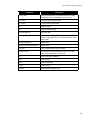
Dialer Settings
The Dialer Settings dialog (see Figure 13) allows
for the programming of various communications
options.
The 1st, 2nd and 3rd Telephone Numbers can be up
to 32 digits. Special digits may be used to perform
the following functions:
•
•
•
•
•
HEX (B)-simulates the [*] key
HEX (C)-simulates the [#] key
HEX (D)-forces the panel to search for dial
tone; must be first digit of telephone
number
HEX (E)-forces the panel to pause for 2
seconds
HEX (F)-end of telephone number marker
Figure 14: Dialer Settings
The first number is the primary number, the
second number is for a second monitoring station, and the third number is the backup number for
the first number.
The 1st and 2nd Account Codes identify the system to the central station when a communication is
sent. The code can be programmed for up to four digits. The first and third telephone number
transmit the first account code. The second telephone number transmits the second account code.
The 1st and 2nd # Format setting affects the type of communication that the dialer sends to the
central station. There are seven formats available including Contact ID, SIA and a pager format.
25
MR-2100/2200 Programming Manual
The Dialer Settings window has the following push buttons along the right side:
•
•
•
•
•
•
Exit: Close the Dialer Settings window and return to the IDs window.
Configuration 1: Display the Dialer Configuration 1 dialog.
Configuration 2: Display the Dialer Configuration 2 dialog.
Call Directions: Display the Call Directions dialog.
Zone Data: Display the Zone Data dialog.
Maintenance/Common: Display the Dialer Maintenance and Common Reporting Codes
dialog.
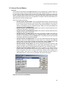
Dialer Configuration 1
The Dialer Configuration 1
dialog (see Figure 14)
contains
the
First
Communicator
Options,
Second
Communicator
Options and International
Options.
The Communications option
determines if the dialer will
communicate to the central
station. When Enabled is
selected, the dialer will
communicate all events as
programmed.
When Figure 14: Dialer Configuration 1
Disabled is selected, the
dialer will not communicate any events.
The TLM One/Two Check options determine whether the dialer will test for telephone line faults on
line one and line two respectively.
The Third Phone # can be programmed for two different modes of operation. When Alternate
Dialing Enabled is selected, the dialer switches between the first and third telephone numbers
after each dialing attempt, until the maximum number of dialing attempts have been made to each
number. When Third Number Backup is enabled, the dialer will use the third telephone number
only if all attempts to communicate to the first telephone number fail. If all attempts to
communicate to the third number also fail, a failure to communicate trouble will be generated.
When Disabled is selected, the third telephone number is not used.
The Dialing option has three different options for pulse or DTMF dialing. If All attempts Pulse is
selected, the dialer will always use pulse (rotary) dialing. If All attempts DTMF Dialing is selected,
the dialer will always use DTMF dialing. If 4 attempts DTMF then Pulse is selected, the dialer will
use DTMF dialing for the first four attempts. If unsuccessful, the dialer will switch to pulse (rotary)
dialing for the remaining attempts.
The SIA Rep. Codes option determines whether the dialer will send the automatic reporting codes
that are in the dialer, or use the reporting codes that are programmed in the Zone Data and
Maintenance/Common reporting codes sections. See See “7.0 Appendix D: Table of Reporting
Codes” on page 60 for a list of the automatic SIA Reporting Codes.
The SIA Max Events option sets the maximum number of events the dialer will send for one SIA
transmission. When 20 per Round is selected, SIA sends a maximum of 20 events per round.
When 8 per Round is selected, SIA sends maximum of 8 events per round.
The Contact ID Rep. Codes option determines whether the dialer will send the automatic reporting
codes that are in the dialer, or use the reporting codes that are programmed in the Zone Data and
26
MR-2100/2200 Programming Manual
Maintenance/Common reporting codes sections. See See “7.0 Appendix D: Table of Reporting
Codes” on page 60 for a list of the automatic Contact ID Reporting Codes.
The Test Transmission Line option determines how the dialer chooses a telephone line to send the
automatic test transmission. If Alternate is selected, the dialer will alternate between using
Telephone Lines 1 and 2 for transmissions, regardless of telephone line troubles. If Available is
selected, the dialer will use Telephone Line 1 for transmissions. If a trouble exists on Telephone
Line 1, the dialer will switch to Line 2.
When the Force Dialing option is set to enabled, if the first attempt by the panel to call the
monitoring station fails, on every subsequent attempt the panel will dial regardless of the presence
of dial tone. When Disabled is selected, the panel will not dial the programmed telephone number
if dial tone is not present.
When the Busy Tone Detection option is enabled, if busy tone is detected, the dialer will disengage
the phone line and try to place the call again following the delay between dialing attempts. When
Disabled is selected, the dialer will use the standard dialing procedure for every attempt.
The Pulse Make/Break Ratio option is for panels in international applications. When 40/60 is
selected, the pulse dialing make/break ratio is the 40/60. When 33/67 is selected, the pulse dialing
make/break ratio is 33/67.
The Handshake option determines the handshake used for BPS transmissions. When 1600 Hz is
selected, the dialer responds to a 1600 Hz handshake. When Standard is selected, the dialer
responds to the handshake designated by the format selected (1400 or 2300 Hz).
The ID Tone can be set to 1300Hz or 2100 Hz. The panel will emit a tone at the selected frequency
for 500 ms every 2 seconds when it places a call to indicate that it is a digital equipment call, not
voice. When Disabled is selected, this feature will not be used.
Dialer Configuration 2
The Dialer Configuration
2 screen (see Figure 15)
contains the Swinger
Shutdown Variables, Test
Transmission options and
Other Options.
The Swinger Shutdown
options determine the
maximum number of
zone events and trouble
events that the dialer will
transmit in one day. The
trouble or alarm will still
be displayed on the panel
and logged in the archive,
but the dialer will not
transmit the event. There Figure 15: Dialer Configuration 2
are individual counters for
Zone Alarm and Restore, Zone Supervisory and Restore, Zone Trouble and Restore and
Maintenance Trouble and Restore. This feature will be reset at midnight. To disable the feature,
program 000.
The Test Transmission Time of Day determines when the automatic test transmission will occur.
The entry is four digits (HH:MM). To disable the feature, program the time as [9999].
27
MR-2100/2200 Programming Manual
The Test Transmission Cycle determines the number of days between test transmissions. This is
automatically set so that tests are performed daily and may not be varied.
Note: If an upgraded database has a value other than 1, choose Set Default to reset the value.
The TLM Trouble Delay controls the number of telephone line monitoring checks required before a
telephone line trouble is generated. The dialer checks the telephone connection at 10-second
intervals.
The Maximum Dialing Attempts to Each Phone Number is the number of attempts that the dialer
will make to each telephone number before generating a fail to communicate trouble.
Post Dial Wait for Handshake is the amount of time the dialer will wait for a valid initial handshake
from the receiver after dialing the programmed telephone number.
Call Directions
The Call Directions dialog (see
Figure 16) contains the options that
determine
which
telephone
numbers
will
be
used
to
communicate events.
There are five different types of
events that can each be sent to
telephone number one or telephone
number two. The event types are
Fire
Zone
Alarm/Restore,
Supervisory Zone Alarm/Restore,
Zone Trouble/Restore, Maintenance Figure 16: Call Directions
Trouble/Restore
and
Test
Transmissions.
Note: UL Listing requires that the Test Transmission be sent to both telephone numbers
Zone Data
The Zone Data dialog (see Figure 17) contains zone definitions and reporting codes that the dialer
will use to communicate events.
28
MR-2100/2200 Programming Manual
The Groups List is a list of all
currently defined groups. Each
line entry includes the Group ID
and its message/description. Click
on the desired group in order to
program it.
The Definition specifies the
identifier of the alarm or trouble
being sent to the central station.
The zone types that are available
are Fire, Sprinkler, Heat, Water
and Untyped.
The Reporting Codes are used
when SIA or Contact ID is set to
Programmed, or when using BPS
formats. There are six reporting
Figure 17: Zone Data
codes for each group. They are:
•
•
•
•
•
•
Zone Alarm Reporting
Code
Zone Alarm Restoral Reporting Code
Trouble Reporting Code
Trouble Restoral Reporting Code
Supervisory Reporting Code
Supervisory Restoral Reporting Code
Dialer Maintenance and Common Reporting Codes
The Dialer Maintenance and
Common
Reporting
Codes
dialog (see Figure 18) contains
maintenance
and
common
reporting codes that the dialer
will use to communicate those
events.
The Reporting Codes List is a
list of all available maintenance
and common reporting codes.
Select one to program its
reporting code.
The Reporting Code is used
when SIA or Contact ID is set to
Programmed, or when using
BPS formats. There are many Figure 18: Dialer Maintenance and Common Reporting
different reporting codes in this Codes
group.
29
MR-2100/2200 Programming Manual
2.9 Circuits and Devices Windows
Overview
The Circuits Window (see Figure 19) allows for the defining of addressable input circuits. The
Devices Window (see Figure 20) allows for the defining of addressable devices. These two
windows are nearly identical. Most controls on one are found on the other with the few exceptions
noted. The current Circuit or Device is shown in the Title Bar of the window.
Figure 19: Circuits Window
Figure 20: Devices Window
Circuit List
The Circuit List is located in the top left corner of the window. It is shown on the Circuits Window
only. This lists any defined circuits for the current panel. Each circuit shows the circuit number,
type of circuit and function if applicable. The highlighted circuit is described in the title bar of the
30
MR-2100/2200 Programming Manual
Circuits Window. Unused circuits are shown using three dashes. Use the <Backspace> key in
order to quickly re-position the current selection to another circuit. The <Up> and <Down> Arrow
keys change the current circuit. The <Right> and <Left> Arrow keys change the type of the
current circuit. The <Plus> and <Minus> keys change the function of the current circuit.
Circuit Type Selector
The Circuit Type Selector is
located below Circuit List on the
left hand side. It is shown on the
Circuit Window only. It is a drop
down box used to assign the
current circuit type. If the circuit is
unused, select not assigned.
Only options supported by the
Input
Circuit
Modules
programmed for the current panel
are assignable.The Device List is
located in the top left corner of
the window. It is shown on the
Devices Window only. It lists any
defined addressable devices for Figure 21: Devices Window
the current addressable circuit,
the two entries for a dual end-of-line circuit, and the separate smoke detector and n/o contract
device for a Smoke Detector + N/O Contact circuit. For addressable devices, the type of device
and its function are shown for each one. Unused addresses are shown with three dashes. Use the
<Backspace> key in order to quickly re-position the current selection to another device. The
<Up> and <Down> Arrow keys change the current device. The <Right> and <Left Arrow>
keys will change the type of the current device. The <Plus> and <Minus> keys will change the
function of the current device.
Note: Both devices listed for Dual end-of-line and Smoke Detector + N/O Contact circuits must be defined.
Device Type Selector
The Device Type Selector is located below Device List on the left hand side. It is shown on the
Device Window only. It is a drop down box used to assign the current device type. Ion, Photo,
Thermal, Acclimate, Dual Acclimate, or Laser. For addressable circuits, it displays all the sensors
or modules that can be programmed for the current device address, sensors for addresses 1 to 99
and modules for addresses 101 to 199. If the address is unused, select not assigned. The
following module types are available:
•
•
•
•
•
Monitor (Class B): This is a standard monitor module using Class B (Style B) wiring and
an end-of-line resistor. This must be chosen for MRI-M500DM, MRI-M501M and MRIM503M modules.
Monitor (Class A): This is a standard monitor module using Class A (Style D) wiring. This
can be used only with the MRI-M500M and MRI-M502M modules.
Control (supervising): This programs the MRI-M500S for use as a generic signalling
circuit. It can be turned on by alarm or supervisory inputs. It will remain on until the system
is reset.
Control (relay): This is used for programming the MRI-M500R relay module.
Control (Bell): This programs the MRI-M500S as a standard signalling circuit. It will turn
on continuously when activated by an alarm. They will silence when the Signal Silence
button is pressed. It does not sound codes.
31
MR-2100/2200 Programming Manual
•
•
•
Control (Strobe): This programs the MRI-M500S as a signalling circuit for use with
strobes. They are non-silenceable and will be turned on continuously for both Alert and
Evacuation mode operation. Strobe circuits cannot be silenced until the system is reset
(unless the strobe duration is programmed – see Strobe Duration in section 2.5.2).
Control (C-Releaser): This programs the MRI-M500S as a continuous releaser which
remains on until an alarm is received on a zone activating the releaser. The releaser is
then turned off after the Delay until the panel is reset. The Delay can be from 0 to 180
seconds.
Control (M-Releaser): This programs the MRI-M500S as a momentary releaser which is
inactive until an alarm is received on a zone activating the releaser. The releaser is then
not activated until after the Delay time. The releaser is turned off after the Duration time, or
the activating zone and panel are reset. Momentary releasers function normally during an
AC power fail. The Delay can be from 0 to 180 seconds and the Duration can be up to
1800 seconds. 1800 seconds is 30 minutes. A Duration of zero (0) will cause the releaser
to stay on until it is reset.
Function Type Selector
The Function Type Selector is used to display and edit the function of the current input point. The
following function types are available:
•
•
•
•
•
•
•
•
•
Alarm: This is a generic fire input. Displays **ALARM** in the Alarm List when activated.
Pull Station: This is a fire input similar to Alarm. The differences are it displays **PULL
STATION** in the Alarm List and may not have a retard time programmed.
Waterflow: This is a fire input similar to Alarm except that it displays **WATERFLOW** in
the Alarm List. Bell circuits can be made non-silenceable for waterflow type inputs (see
section 2.3 System Window).
Supervisory: This is used for such inputs as Low Water Pressure, Sprinkler Shut Off
Valve Closed, etc.
Halt: This causes the related releaser outputs to not operate. The supervisory LED will be
turned on by activation of this type of input.
Abort: This causes the related releaser outputs to have their associated timers to be
stopped. The timers will start to run again when the input goes back to normal. The
supervisory LED will be turned on by activation of this type of input.
Monitor: This is used to monitor the action of items such as dampers, door, fans, etc. The
supervisory LED is used. Monitor inputs can operate relays and control modules.
Non-reporting: This is a non-latching type of input. They can only operate LEDs, function
relays and control modules. The supervisory LED will be operated. Outputs operated by a
Non-reporting input cannot be also operated by another type of input or switch.
Trouble: This function type is used for various circuit types and for control modules.
Trouble type inputs operate LEDs only, no other outputs are allowed. This function type is
assigned by MHI automatically.
Message
The Message is located in the middle of the top of the window. This 3 line by 20 character text
message is displayed or printed for all signals originating from the current input point. Circuit types
that use devices have a default message created for them when defined. This message can be
changed.
Use Grp Message
The Use Grp Msg check box is used if the input point is to use a group message. A text entry box
appears when the box is checked. Enter the ID of the group message to be used. Only one ID can
be entered. If a group message is being used, it is displayed in the Message area, but the
message cannot be altered.
32
MR-2100/2200 Programming Manual
Input Circuit or Device Options
There are a number of options that can be used for each input circuit or device. Not all options
apply to all inputs. MHI only shows those options that are currently usable. The following options
are available:
•
•
•
Enable Fan Delay: Controls the staggered turning off of Control Modules (relay). If
checked, Control Modules (relay) on this circuit are turned off in sequence, from the lowest
address to the highest address, at a rate set by the Fan Delay option in the Panel Options
Dialog, when Reset is pressed on the panel. The operation of Control Modules
(supervising) is not affected by this setting.
Disable Maintenance Alert: Disables the addressable smoke or heat sensor from
reporting Maintenance Alert. Maintenance Alert is defined by the device staying at almost
alarm threshold for an extended period of time. This is usually an indication that a smoke
sensor requires cleaning. Heat sensors in high temperature areas may need the
Maintenance Alert disabled to limit nuisance troubles. Standard room temperature (20°C)
does not cause a Maintenance Alert on a heat detector.
Code Bells: Checking this option causes only selected coded bells to sound coded
signals. If coded bells are used the following options are then also shown:
-- No Restore: If checked, the panel does not sound the Code again when the input
restores. If not checked, the panel sounds a single round of the Code when the input
restores
-- Code: This is the sequence that is sounded when an alarm is received on this input. It
can be up to 4 digits long. Hexadecimal digits are used, thus each digit can be from 1 to
F, where A=10, B=11, C=12, D=13, E=14 and F=15.
-- Round: This is the number of times the Code is repeated. It can be between 1 and 4
times for no restore inputs, and between 2 and 4 for restore inputs. Note: A minimum of
three rounds of code is required per NFPA 72.
•
•
•
Night Sens. and Day Sens.: Selects the Alarm threshold sensitivity for addressable
smoke sensors. Heat sensors always use Normal sensitivity. Increased sensitivity causes
alarms at lower levels of smoke. Sensors not attached to a switch always use the Night
Sensitivity. Sensors attached to a switch use Night Sensitivity while the switch is Off and
Day Sensitivity while the switch is On. Night Sensitivity must always be equal to or more
sensitive than the Day Sensitivity.
Manual Restart: Check this to require that the control module not be reset by System
Reset but by Manual Restart. Use of this option requires that there be a Manual Restart
function key assigned to the panel.
Trigger Manual Restart: Check this option to have a monitor module generate a Manual
Restart when activated. Module Restart must have Non-reporting function.
33
MR-2100/2200 Programming Manual
Pushbuttons
The push buttons located on the right hand side are:
•
•
•
Exit: Closes the window and returns to the previous window.
Devices: Opens the Devices Window for the current circuit (Circuits Window only).
Copy: Copies the circuit/device information, relates and message from another input to
the current input (see Figure 21). The current input does not have to be defined. Relates
cannot be copied between conventional and addressable input points. The Panel ID,
Circuit ID and Device ID (not always shown) list the circuit/device to be copied from.
Marking Transfer Main Definition copies the listed circuit/device type and function to the
current circuit/device. Note: Not all inputs can be copied to all other possible inputs.
Marking Transfer Relates copies the relates from the listed circuit/device relates to the
current one. This may cause some invalid relates. Marking Transfer Message causes the
message to be copied. Marking Transfer Devices (if shown) copies any device definitions
that the listed circuit contains. These devices copy messages and relates as based on
those settings above. There is no checking made at this time as to the validity of the
values copied. Unexpected results can occur if care is not taken. For each database
that is created, a warning about using copy is shown. Marking the check box in the
warning stops the box from appearing again for the database. This option can help speed
up the creation of a database. By completely defining one input, these values can be
copied to all other inputs, making any minor changes that are required after the copy.
Figure 22: Copy Window
•
•
•
34
Relate or Trbl Relate: Opens the Relate Window for the current circuit or device. This
allows for the programming of outputs, LEDs, relays and control modules to be operated
when the input goes into alarm. The Relate button displays all output types that are
available depending on the function type of the input. The Trbl Relate button displays only
LEDs that can be related. Note: All panel outputs and control modules to be operated
must be defined before they can be included in the relates of an input.
Map: Displays and/or updates the Map Window. See section 2.8 Map Window of the
Modul-R Human Interface User Guide.
Verify List: Displays the Verify List. If there is no Verify List, a requester will appear asking
whether you wish to perform a verification. See section 2.6.5 of the Modul-R Human
Interface User Guide for a full description of the Verify List and its uses.
MR-2100/2200 Programming Manual
2.10 Internal Circuits Window
Overview
The Internal Circuits Window (see Figure 22) allows for the programming of outputs, LEDs, etc.
for the various internal circuits (functions) of the Control Panel. Internal circuits 0, 71, 72, 73, 75,
81, and 82 are fire alarm functions while all others are trouble functions. All internal circuits have
specific meanings and are stored in the archive of the panel. MR-2944 and MR-2934 annunciators
only use internal circuits 51 and 52. See “4.0 Appendix A: Condition Codes and Zone Numbers” on
page 46 for a list of all the internal circuits.
Some of the internal circuits are:
•
•
•
•
•
•
•
Internal Circuit 0, General Alarm: This is the General Alarm function. General Alarm can
be received from an annunciator or from an SE 2000. It can be assigned to one of the Hot
Keys of control panels. General Alarm causes all the bells and strobes on the panel to
operate in Evacuation mode. Any additional outputs, LEDs, etc. that require operation are
programmed using the Relate button.
Internal Circuit 51, Comlink #1 Supervision: This is used for communications errors on
COM1 port of the panel or annunciator.
Internal Circuit 52, Comlink #2 Supervision: This is used for communications errors on
COM2 port of the panel or annunciator.
Internal Circuit 81, 1st Stage Alarm: This circuit is activated if the bells and strobes are
activated in first stage by an alarm input. Any additional outputs, LEDs, etc. that require
operation are programmed using the Relate button. If the bells have been disconnected
on the panel, this circuit will not be generated.
Internal Circuit 82, 2nd Stage Alarm: This circuit is activated if the bells and strobes are
activated in the second stage mode by an alarm input or by a time-out. Any additional
outputs, LEDs, etc. that require operation are programmed using the Relate button. If the
bells have been disconnected on the panel, this circuit will not be generated.
Internal Circuit 96, Fire Pre-alarm: This circuit is activated by any smoke detector in the
auto-verify process or addressable device in alarm during the Retard period. It can be
related to an LED to give a visual indication that an alarm is in the verification process.
Internal Circuit 99, Common Trouble: This circuit is tripped by any internal circuit or
trouble condition not associated with an internal circuit that turns on the Common Trouble
LED on the panel. This circuit is used to annunciate common trouble conditions at a
remote location. This circuit is not tripped by troubles generated by input circuits or
addressable devices. This circuit is not recorded in the archive of the panel.
Figure 23: Internal Circuits Window
35
MR-2100/2200 Programming Manual
Internal Circuits List
The Internal Circuits List displays all of the internal circuits for the current Control Panel. Each line
includes the internal circuit number, its description and if relates have been assigned.
Warning: Some of the internal circuits (e.g. checksum) do not have restore signals associated
with them. They generally relate to a condition that requires either service work or a reboot of the
panel. Any relates assigned to such an internal circuit have no way to be reset short of re-booting
the entire network.
Pushbuttons
The following push buttons are available:
•
•
•
•
•
•
•
List Entries: This new feature allows the user to control the information displayed.
Relevant only lists items applicable to the current version only. All lists all possible items
so that relates made on previous versions may be removed.
Exit: Closes the Internal Circuits Window and returns to the Panel Window.
Reset: Clears all relates associated with the current internal circuit.
Relate: Opens the Relate Window for the internal circuit. This allows for the programming
of outputs, LEDs, relays and control modules to be operated by the internal circuit.
Copy Relates: Copies the relates from another input to the current internal circuit (see
Figure 21). The values of the panel and circuit are required. Press Copy to copy the
information. If the function type of the two circuits is different, a requester is presented to
confirm the copy.
Map: Displays and/or updates the Map Window. See section 2.8 Map Window of the
Modul-R Human Interface User Guide.
Verify List: Displays the Verify List. If there is no Verify List, a requester will appear asking
whether you wish to perform a verification. See section 2.6.5 of the Modul-R Human
Interface User Guide for a full description of the Verify List and its uses.
2.11 Relate Window
Overview
The Relate Window (see Figure 23) allows for the relating of inputs, switches and groups to
outputs, LEDs, relays, etc. These relationships are used by the panel to determine which outputs
to operate for alarm and trouble states. Inputs can operate bells/strobes, LEDs, relays, control
modules on any panel in the system. Switches can operate relays, LEDs, control modules on any
panel in the system and control the day/night sensitivity change of any addressable detector on
any panel. The title bar describes the current input point/switch/group and current output panel or
annunciator.
Figure 24: Relate Window
36
MR-2100/2200 Programming Manual
Groups
Groups is a comma separated list of all the groups that the point is to use for relates. Up to ten
groups can be listed. These groups are assigned to the point itself and does not change as the
current output panel changes. Relates that are part of the groups are not shown in the Relate
Window but can be shown on the Map Window if so desired.
Panel List
The Panel List is a list-box located in the top left corner of the window. It lists all the panels, both
Control and Annunciator, that are defined in the system along with their panel message. The highlighted entry in the list is the one that is being related to by the current input. When a different
panel is selected, all the controls in the window change to reflect this. Use the <Backspace> key
in order to quickly re-position the current selection to another panel.
Outputs List
The Outputs List shows the programmable outputs of the panel. It is not shown for annunciators. It
lists all outputs, along with their definition and current state. The states are *on* for selected, blank
for not selected, act if they activated by default, and n/a for not available. A blank definition is for
unused outputs. Bell and Strobe outputs can only be selected for Fire Alarm type inputs. If
Complex Releasers are enabled, releasers can have three other states: Fast which operates the
releaser immediately regardless of any delay that is programmed in; *A* or *B* which allow for
AND logic. The releaser will not operate until both an A and a B input have been activated. Use the
<space> key or double click on the entry to cycle between available selections. Use the
<Backspace> key in order to quickly reposition the current selection to another output.
Relays List
The Relays List shows the general purpose function relays of the panel. It is not shown for
annunciators. Each is listed by number and state. The states are *on* for selected, n/a for not
available, and blank for not selected. Use the <space> key or double click on the entry to cycle
between available selections. Use the <Backspace> key in order to quickly re-position the current
selection to another relay.
LEDs List
The LEDs List shows the LED zones available on the panel or annunciator. This is not shown if the
panel has no LEDs. Each is listed by number and state. The states are *on* for selected, blank for
not selected and n/a for not available. Use the <space> key or double click on the entry to cycle
between available selections. Use the <Backspace> key in order to quickly re-position the current
selection to another LED. The actual number of LED zones varies depending upon the panel or
annunciator.
Device List
The Device List shows the addressable devices that can be related to the current point. For
system inputs and groups, it is displayed only if there are any control modules defined for the
panel; for switches, it is displayed if there are any addressable detectors or control modules
defined. Each entry shows the devices’s address (panel.circuit.device), its state and its device
message. The states are *on* for selected and blank for not selected. Devices that are not
available are not shown. Use the <space> key or double click on the entry to cycle between
available selections.
Evac
THe EVAC checkbox is an option for fire alarm type inputs only. Checking this option will cause all
bells and strobes to operate in second stage (evacuation) mode.
37
MR-2100/2200 Programming Manual
Msg Receive Check Box
The Msg Receive check box is an option for annunciators with LCDs only. If marked, this
annunciator receives messages about this input point to display in its Alarm List. If not marked, the
annunciator does not receive messages about this input point to display in its Alarm List.
Pushbuttons
The push buttons, located on the right side of the window, are:
•
•
•
•
38
Exit: Closes the Relate Window and returns to the previous window.
Map: Displays and/or updates the Map Window. See section 2.8 Map Window of the
Modul-R Human Interface User Guide.
Verify List: Displays the Verify List. If there is no Verify List, a requester will appear asking
whether you wish to perform a verification. See the Modul-R Human Interface User Guide
for a full description of the Verify List and its uses.
View Groups: Displays the Groups Window. This is for reviewing the defined groups. No
editing can be done to the groups. To edit the groups, return to the System Window.
MR-2100/2200 Programming Manual
3.0 LCD Programming
3.1 Introduction
This chapter describes the panel components that are programmed via the LCD and keypad.
3.2 General Comments
About the LCD Menu
A number of items are programmed through the LCD and keypad. This is called the LCD menu. All
options are under the PROGRAM option on the Main Menu of the panel. The Main Menu can be
recalled to the LCD by pressing <Home>.
Note: The only item that must be programmed from the LCD menu is the Panel ID. This must be
done before the database is downloaded.
There are multiple levels of program access. Privilege Level 0 is the base level of operation.
Privilege Level 1 allows access to privileged Hot Key functions and limited programming. Privilege
Level 2 allows programming of almost all system parameters. (Note that a Service Mode Trouble
occurs when logged in Level 2.) Higher Privilege Levels are reserved for Secutron's own use and
are not discussed here. Certain functions can be assigned to different privilege levels. These
functions default to the higher of the two privilege levels.
While programming through the LCD menu, the panel beeps once when a valid key is pressed and
beep three times if an invalid key is pressed. Programming is done through a series of menus and
requester screens. The menus present options to display other menus, show information, or
request information. Menus have a ">" or "<" next to the description of each item. Use the arrow
keys on the keypad to move the cursor and press <Enter> to select. In Figure 24, pressing
<Enter> brings up the Program Menu.
Title
Menu Item
Selected Menu Item
Module-R by Secutron
12:22
>STATUS
HISTORY<
>PROGRAM PASSCODE<
Menu Item
Menu Item
Figure 25: Program Menu
A menu option of more displays further menu options that do not fit on the current screen. All the
screens of a menu loop around continuously. The default option, ie the option next to the cursor, is
the one to the upper left of the screen. Generally, but not always, more is the default option.
Selector screens (see Figure 25) are screens where options are toggled on or off. Options that are
on are marked by an asterisk(*) while options that are off are marked with a dash (-). Use the left
and right arrow keys to move the cursor to the desired option and press <Enter> to change it.
Move the cursor to OK and press <Enter> to save any changes, or press <Clear> to lose any
changes. In Figure 25, the alarm and trouble relays are selected and the supervisory relay is not
selected to be disconnected when the Common Disconnect hotkey is pressed. Pressing <Enter>
causes the alarm relay to be not selected.
39
MR-2100/2200 Programming Manual
COMMON DISCONNECT
Title
Options
Selections
A S T
- *
*
OK<
Figure 26: Selector Screen
For all screens, <Clear> returns to the previous menu level without changing any information and
<Home> returns to the Main Menu without changing any information.
3.3 Menus
Clock Menu
This menu has the following options:
•
•
Date: View or change the date. The date is entered in MM.DD.YY format. Each section of
the date must be separated by a dot. Press <Enter> to accept date typed. <Clear>
removes any digits typed. If no digits are displayed, <Clear> returns you to the Clock
Menu. The new date is sent to all other panels on the Network, if used. All panels assume
this date. The date change is recorded in the Archive.
Time: Change the time. The time is entered in HH.MM.SS format. Each section of the
time must be separated by a dot. All times are in 24 hour format. Press <Enter> to accept
time typed. <Clear> removes any digits typed. If no digits are displayed, <Clear>
returns you to the Clock Menu. The new time is sent to all other panels on the Network, if
used. All panels assume this time. If <Enter> is pressed with no time entered, the current
time is sent to all panels on the network. If a change of greater than 5 minutes occurs, the
new time is recorded in the archive.
Note: 1. The Master Panel in a network synchronizes all clocks in the network at 03:30 every day,
sending both date and time.
2. Changing the time while the panel is calibrating aborts the calibration.
•
Calibrate: Calibrates the clock so that it keeps correct time. Calibration takes 2 to 45
days. Waiting longer gives more accurate results. The panel functions normally while
calibrating. When sufficient time has passed, re-selecting this function asks for the correct
time. The calibration is then be reported. In a network, only the master panel needs to
calibrated.
Note: Changing the time using the Time option aborts the calibration. If a panel is currently in a
calibration, it ignores time changes sent over the network.
Common Relays Menu
This function is restricted to Privilege Level 2. The menu has the following options:
•
•
40
Disconnect: View or change the relays that can be disconnected by the Common
Disconnect hot key. Selected relays are marked by an asterisk (*). To change the
selection, move the cursor to the desired relay A(larm), S(upervisory) or T(rouble) and
press <Enter> to change. Select OK when done. <Clear> returns you to Program Menu
without making changes.
Test Inhibit: View or change whether common relays are disconnected during Test Mode
or not. <Clear> returns you to Program Menu without making changes.
MR-2100/2200 Programming Manual
Switches Menu
This function can be set to Privilege Level 1 or 2. View or change the status of any switches.
These switches can be set to On, Off or Auto. The Auto state only applies to switches that have a
timer associated with them. The Auto state allows the switch to follow the timer settings. Any
changes made are broadcast to the network so that all panels have the same state. Settings are
retained by the panel if it is re-booted and the Master Unit broadcasts its settings to the network
upon start up. See Switches Window for information on programming what the switch affects.
The menu has the following options:
•
•
•
Individual: View or change the status of an individual switch. Each switch is shown in
turn. If a switch has no timer, the Auto option is not shown.
All Off: Force switches into the Off mode. The number displayed is the number of timers
that are switched On. This option is shown only if no switches have timers associated with
them.
All Auto: Force all switches with timers to Auto mode. All switches with timers go into the
state dictated by the time. The number displayed is the number of switches with timers
forced On or Off. This option has no effect on switches without timers. This option is not
shown if no timers are associated with the switches.
Battery
Displays the current battery status. The display shows:
Line 1: Screen Title
Line 2: AC State (diagnostic use only)
Line 3: Current State of the Battery and Menu Option (see below)
Line 4: Menu Options (listed below)
The menu has the following options:
•
•
•
OK: Return to Program Menu.
Test: Force an immediate battery test.
Calibrate: This function is restricted to Privilege Level 2. This calibrates the Battery
Charger. The batteries must be disconnected before beginning calibration. No keypad
control is provided during calibration. The calibration display will return when calibration is
over. Calibration only needs to be done when the configuration is erased. All Battery
Chargers come calibrated from the factory.
Addressable
The menu has the following options:
•
•
•
Reset Max/Min: Clears the stored values for the maximum and minimum values returned
by the addressable devices. These values are automatically cleared when the panel
reboots.
Duplicates Check: This causes an immediate check to see if more than one device is
using an address. The panel automatically does this check on the hour.
LED Mode: This controls how the LEDs on the devices are used. There are three options:
-- OFF/FLASH: The device LEDs are normally off and flash when an alarm is reported.
The flashing LED is reset when System Reset is pressed.
-- FLASH/ON: The device LEDs flash each time they are polled. They latch on in Alarm.
The LEDs are reset when System Reset is pressed. Note: Due to current draw
limitations, only the first 5 detectors on a circuit latch their LEDs. This has no effect on
other panel operation.
-- OFF/ON: The LEDs are normally off and latch on in Alarm. The LEDs are reset when
System Reset is pressed. Note: Due to current draw limitations, only the first 5
detectors on a circuit latch their LEDs. This has no effect on other panel operation.
41
MR-2100/2200 Programming Manual
-- RESET: This functions resets the LEDs to their off state.
•
Sensitivity: This function is restricted to Privilege Level 2. This allows for the manual
adjustment of the sensitivity of addressable detectors. All devices have a default
sensitivity assigned in the database. The detector can be set to the database default value
or to one of the pre-defined levels replacing the database values. These manual values
are retained if the panel is re-booted.
-- SELECT: Change the manual sensitivity of addressable detectors. The first screen asks
for a circuit and device number. Enter the circuit and device or press <Enter> without
entering any number to view the first detector in the database. Each detector is
displayed in turn, showing the current sensitivity and allowing for it to be changed or the
next detector to be displayed. Press <Clear> to stop viewing the detector list.
-- PRINT: Print a list of all detectors that have a sensitivity other than the one selected in
the database. This option is not shown if no manual sensitivities have been set.
-- ALL DEFAULT: Change all manual sensitivity settings to the default values set in the
database.
•
Bypass: This function can be set to Privilege Level 1 or 2. This selects devices to be
bypassed. A bypassed device is ignored by the system. Addressable bypasses are
retained when the panel is re-booted. Only devices included in the database can be
bypassed. Bypasses are annunciated by a common trouble condition. The Bypass menu
has the following options:
-- ON: Select devices to be bypassed. Enter the circuit and device number. Press
<Enter> to accept the device and to enter the next one. Pressing <Clear> removes
any numbers entered. Pressing either <Enter> or <Clear> with no numbers
displayed ends the input mode.
-- OFF: Select bypassed devices to be returned to normal operation. Each bypassed
device is listed in order. Select next to keep the bypass on or select OFF to remove the
bypass. After the last device, display returns to the Bypass menu. Press <Clear> to
return to the Bypass Menu. This option is not available if there are no devices
bypassed.
-- ALL OFF: Remove all bypasses, if any, from the system. The number of bypassed
devices is displayed next to this option.
•
Test: Select devices to be tested. Test Mode must be active for this selection to be
available. All devices selected for testing are automatically deselected when Test Mode is
turned off. The Test Menu has the following options:
-- ON: Select devices for testing. Enter the circuit and device number, or enter the circuit
number only to select all devices on the circuit. Press <Enter> to accept the device
and to enter the next one. Pressing <Clear> removes any numbers entered. Pressing
either <Enter> or <Clear> with no numbers displayed ends the input mode.
-- OFF: Select devices under test to be returned to normal operation. Each device under
test is listed in order. Select next to keep the device under test or select OFF to remove
the test mode. After the last device, display returns to the Test menu. Press <Clear> to
return to the Test Menu. This option is not available if there are no devices selected for
testing.
-- ALL OFF: Remove all devices being tested, if any, from the test mode. The number of
devices being tested is displayed next to this option.
•
42
Control Modules: This function can be set to Privilege Level 1 or 2. Allow for the manual
operation of the control modules included in the database. There are three states
available: Automatic (controlled by device inputs), Manual On, and Manual Off. This mode
is retained if the panel is re-booted. Manually controlled modules are annunciated by a
common trouble condition. The menu has the following options:
MR-2100/2200 Programming Manual
-- SELECT: Change the Auto/On/Off state of control modules. The first screen asks for a
circuit and device number. Enter the circuit and device or press <Enter> without
entering any number to view the first control module in the database. Each control
module is displayed in turn, showing the current state and allowing for it to be changed
or the next control module to be displayed. Press <Clear> to stop viewing the control
module list.
-- ALL AUTO: Change any control modules that are forced on or off back to automatic
mode.
Archive
This function is restricted to Privilege Level 2. View and change the settings for the recording of
optional entries into the history. The following items can be included or not included in the history:
•
•
•
Test: View or change whether Test signals should be recorded in the history. The current
setting is shown in the upper right corner. Test signals are marked as such.
Non-Reporting: View or change whether non-reporting signals are recorded in the history
or not. Non-reporting signals are recorded by default.
Network: View or change the type of archive events that the panel will record in the
archive. This is only available on the network master panel. The options are:
-- LOCAL: Record only panel events in the archive.
-- GLOBAL: Record all events in the archive.
Relays
This function can be set to Privilege Level 1 or 2. If Privilege Level 1 is set and Level 2 is required,
access to the menu is denied. This function allows for the manual operation of the relays. There
are three possible states: Automatic (state determined by inputs), Forced On, or Forced Off. This
mode is retained if the panel is re-booted.
•
•
SELECT: Change the Auto/On/Off state of relay. Each relay is shown in turn, showing the
current state and allowing for it to be changed or the next relay to be displayed. Press
<Clear> to stop viewing the relay list.
ALL AUTO: Change any relays that are forced on or off back to automatic mode.
Ports
This menu has the following options:
•
Network: Allows for the setting of parameters related to the network. If the downloaded
database indicates that there is no network, the only option is Panel ID. The Network
Menu has the following options:
-- Panel ID: This function is restricted to Privilege Level 2. Set the Network ID number.
This is between 1 and 254.
-- Reboot: Cause all panels on the network to do a Hard reboot, ie equivalent to pressing
the Hard Reboot button on the top of the main board. Each panel records in the history
the time it received the Network Reboot command.
-- Global Commands: Sends the selected key (acknowledge, signal silence, or system
reset) to all Control panels and annunciators on the Network. Each unit, including the
sending unit, responds as if that key has been pressed.
-- Retry: Set the number of times to try to resend a message before giving up. If this
number of retries are attempted without success, the other panel or annunciator is
considered to be off-line. The default value is 8.
-- Baud: Set the communications baud rate for Com Port 1. This value may need to be
changed if the default rate (4800) does not allow for communications. Since each
installation is different, this value needs to be chosen by trial and error. If the default rate
43
MR-2100/2200 Programming Manual
does not work, chose the next slower rate. Continue this process until a rate that works
is chosen. The available baud rates are: 9600, 4800, 2400, 1200, 600 and 300. The
recommended rates are: 4800, 2400, and 1200. Below is a table documenting the
maximum wire capacitance allowed on a single port connection.
•
Baud Rate
Maximum Capacitance
9600
100 nF
4800
220 nF
2400
470 nF
1200
680 nF
Port 3: These options are restricted to Privilege 2. The options available vary depending upon
the Port 3 setting in the database. This port can only be disabled from the database.
PC Connect (MR2-8G Program): Allows for the configuration of the communications to a
GRID package. If more than one signal needs to be sent, new alarms take precedence.
-- Baud: Set the communications baud rate. The available fixed baud rates are 9600,
4800, 2400, 1200, 600 and 300.
-- Delay: Sets the length of time the panel will wait before reporting the GRID package offline. This can be set from 10 to 255 seconds.
-- Disconnect: If enabled, the Common Disconnect hot key will shut down Port 3. The
GRID package will report the panel as offline.
Voice Evac.System (MR2-8E Program): Allows for setting parameters related to the
connection to the MV2700 voice evacuation panel.
-- Mode: Selects how information is sent to the MV2700. There are the following options:
DEVICE (default): Send the device address or internal circuit number without
translation.
ZONE: Send the LED number turned on for input circuits and devices and send the
internal circuit for internal circuits.
GROUP: Send the associated Group ID(s) for all conditions. Anything not associated
with a specific group sends a group number of 0.
-- Retry: Set the number of times to try to resend a message before giving up. If this
number of retries are attempted without success, the other panel is considered to be
off-line. The default value is 8. This would be increased only if the communications line
cycles between on-line and off-line. (Range: 1 to 25)
-- Disconnect: If enabled, the Common Disconnect hot key shuts down Port 3.
-- Baud: Set the communications baud rate. The available fixed baud rates are 9600,
4800, 2400, 1200, 600 and 300.
•
•
44
Terminal: Select ANSI or TeleVideo protocol. Most terminals and terminal emulator
programs support ANSI protocol.
Port 6: Allows for the setting of the baud rate to MR-2614 and MR-2644 annunciators, the
city tie modules, and the MRDL dialer. The settings are 4800 and 1200. If none of these
devices are programmed in the database, the message “nothing to program” is shown.
MR-2100/2200 Programming Manual
Alarm List
This menu controls the operation of the Alarm List. This function is restricted to Privilege Level 2. It
has the following options:
•
•
Reset: Select when entries are taken out of the Alarm List. AUTO removes entries as
soon as the condition restores. MANUAL requires that Reset be pressed before they are
removed. Conditions that have restored are shown as a restored condition in the Alarm
List.
Remote: Routes the messages for events from the panel to annunciators. The options
are:
-- ALL: All messages are sent to all annunciators.
-- SELECT: Messages are sent as directed in the database.
Passcode
Allows for the changing of passcodes. The Privilege Level 2 can change both the Level 1 and 2
passcodes, while Level 1 can only change the Level 1 passcode. Passcodes are four digit
numbers in the range 1000 to 9999. Type in the new passcode and press <Enter> to accept.
Asterisks are displayed instead of the numbers. <Clear> removes any digits typed. If no digits are
displayed, <Clear> returns to the Program or Passcode Menu.
The default Level 2 passcode is 2222. The default Level 1 passcode is 1111. These passcodes
should be changed to prevent unauthorized access.
There is a special Level 2 passcode that is variable from day to day. It can be obtained from
Secutron if the Level 2 passcode is forgotten.
Memory
This function is restricted to Privilege Level 2. This menu has the following options:
•
Erase Configuration: This erases all initiating circuit, bell, relay, and privilege values
entered from the keypad and LCD menu, and replace them with default values. With MR2
programs, this has no effect on information contained in the downloaded database.
Confirmation is asked before erasure. After the Configuration has been erased, the panel
must be reset using the reset button at the top of the Main Circuit Board, if the panel does
not do this automatically. The following items are not erased: Serial Number, Clock
Calibration, Level 1 Passcode, Level 2 Passcode, Main Board Type, Input Circuit
Modules.
45
MR-2100/2200 Programming Manual
4.0 Appendix A: Condition Codes and Zone Numbers
4.1 Introduction
This appendix lists the condition codes and zone numbers used by the panel.
4.2 List of Codes and Zone Numbers
Condition Codes
The alarm list and archive use the following formats for condition codes.
Archive
Alarm List
A
ALARM
Alarm
B
bypass
Bypassed Circuit/Device
C
com
Comlink
D
dupl
Duplicate Addressable Device
E
alert
Maintenance Alert
G
ground
H
I
Description
Ground Fault
Hot Key Pressed
ilgl
J
Illegal Addressable Device
Switch
M
msng
Missing Addressable Device
N
nofire
Non-Fire
P
M.PULL
S
spv
Supervisory
T
trbl
Trouble or Parameter Change
U
wrong
W
WFLOW
X
warn
Pull Station Alarm
Wrong Device Type
Waterflow Alarm
Pre-Alert
A plus sign (+) refers to a new or on condition, a minus sign (-) refers to a restoral or off condition,
and an equal sign (=) refers to a one time event.
46
MR-2100/2200 Programming Manual
Zone Number
PPP:ZZ.SSS Format:
PPP
Control Panel Number
ZZ
Panel Zone
Panel
Zone
Description
Panel
Zone
Description
0
General Alarm
802
Privilege Level
1
Initiating Circuit 1
81
1st Stage Alarm
2
Initiating Circuit 2
82
2nd Stage Alarm
50
Network Verify
83
Switch
51
Comlink 1
84
Test Mode
52
Comlink 2
851
Erase Configuration
53
Comlink 3
863
Change Configuration
54
Comlink 6
87
Passcode Tamper
56
MRDL/City-Tie
881
Database Loaded
60
Output (bell/releaser) Supervision
891
Time/Date Change
61
Auxiliary Power Supervision
901
Hot Key Activation
641
Program Checksum
911
Memory Overflow
651
Database Checksum
921
Network Reboot
66
AC Power
931
New Program
67
Low Battery
941
Network Reboot Required who
691
Program Restart
951
Network Reboot Required why
70
Battery Charger
Notes:
1.
2.
3.
4.
These zones do not restore.
Privilege Level 0 generates a restore signal; all others generate a trouble signal.
This zone does not restore and is not repeated sequentially in the archive.
Programs dated before March 4, 1996 use a different numbering sequence. Panels
updated erase the archive the first time the new program runs.
47
MR-2100/2200 Programming Manual
SSS
Sub-Zone Number
Zone
Addressable Circuit
Meaning of SubZone Number
000 - Wiring Fault
All Others - Device Number
Comlink 1 (Zone 51)
Unit Network ID number
Comlink 3 (Zone 53)
Unit ID number
Comlink 6 (Zone 54)
Unit ID Number
1-8
MR-2614
9-16 MR-2644
239
City-tie
240
MRDL/City-tie
Output Supervision (Zone 60)
Output Circuit Number
Auxiliary Power Supervision
(Zone 61)
Auxiliary Power Circuit Number
Program Re-start (Zone 69)
000 - Power On/Hard reboot
001 - Watchdog
002 - Clock Monitor
003 - Illegal Instruction
004 - Unused Interrupt
005 - Orphan Interrupt
48
Privilege Level (Zone 80):
Level Set
Switch (Zone 83):
Switch Number
MR-2100/2200 Programming Manual
Zone
Hot Key Activation (Zone 90):
Function Number of the Hot key
pressed
Meaning of SubZone Number
001 - Fire Drill
002 - Lamp Test
004 - Relay Disconnect
005 - Test Mode
006 - Signal Disconnect
007 - Acknowledge
008 - Signal Silence
009 - Reset
010 - Common Disconnect
011 - General Alarm
016 - Switch 1 On
017 - Switch 2 On
018 - Switch 3 On
49
MR-2100/2200 Programming Manual
Zone
Hot Key Activation (Zone 90):
Function Number of the Hot key
pressed
Meaning of SubZone Number
019 - Switch 4 On
020 - Switch 5 On
021 - Switch 6 On
022 - Switch 7 On
023 - Switch 8 On
024 - Switch 9 On
025 - Switch 10 On
026 - Switch 11 On
027 - Switch 12 On
028 - Switch 13 On
029 - Switch 14 On
030 - Switch 15 On
031 - Switch 16 On
032 - Switch 1 Off
033 - Switch 2 Off
034 - Switch 3 Off
035 - Switch 4 Off
036 - Switch 5 Off
037 - Switch 6 Off
038 - Switch 7 Off
039 - Switch 8 Off
040 - Switch 9 Off
041 - Switch 10 Off
042 - Switch 11 Off
043 - Switch 12 Off
044 - Switch 13 Off
045 - Switch 14 Off
046 - Switch 15 Off
047 - Switch 16 Off
051 - Manual Restart
Network Reboot (Zone 92):
50
Unit ID of panel broadcasting the command
MR-2100/2200 Programming Manual
Zone
Meaning of SubZone Number
Network Reboot Required Who
(Zone 94):
Unit ID of panel generating the Network Reboot
Required trouble
Network Reboot Required Why
(Zone 95)
003 - port 3
006 - negative counter
008 - memory overflow
009 - co-processor memory overflow
010 - network
011 - network
012 - network
013 - network
All Others:
Always 000
51
MR-2100/2200 Programming Manual
5.0 Appendix B: Stand-by Battery Calculation
Batteries are designed and manufactured for a specific use. "Standby" is one of these uses. They
are rated according to their ability to deliver a steady current for 20 hours ("20 Hour Rating"). A 10
Ah battery is unable to deliver 10 A for 1 hour, however it delivers ½ A (500 mA) for 20 hours. A car
battery is designed to deliver "cranking" power for a short time, (a few hundred Amps for a few
minutes). Unfortunately, fire alarm control panels need both of these characteristics, that is, driving
a heavy bell load for a relatively short time, at the end of a 24 hour standby current drain. This
protection necessitates certain over sizing.
Regardless of the standby calculation and tables, the battery must be at least 150% of the bell
load. e.g. A 4 A total bell load necessitates at least 6 A hour battery (in terms of 20 hour rating).
The standard battery options available for the MR-2200 Control Unit are:
a) 4 Ah internal,
b) 7 Ah internal,
c) 10 Ah internal,
d) 24 Ah external in a separate battery cabinet,
e) 35 Ah external in a separate battery cabinet,
52
MR-2100/2200 Programming Manual
6.0 Appendix C: Service Terminal
6.1 General
The MR-2200 Control Unit displays information and accept commands via the service terminal
port. The information includes initiating circuit configuration, current status of bell, relays, etc.,
diagnostic information, the archive, etc. The commands allow for the selection of the information to
view, limited programming and basic operation. Certain Control Unit commands are available only
at certain privilege levels. Units beep once when a valid character is received and three times if an
invalid character is received. If a command is not finished within about 10 seconds, the unit beeps
three times and loses any information sent.
The service terminal program provides the information on a number of different screens. When the
terminal is first connected, it views whatever screen was the last to be viewed. To view Screen 0,
which lists all the screens that are available, press 0<Tab>. Press <Delete> to refresh the
screen. Press the <Tab> key to view the next screen. See below for a complete description on the
<Tab> key commands. Certain Control Unit screens are available only at higher privilege levels.
6.2 Control Unit
Screens
The Control Unit uses 8 data bits, no parity, 1 stop bit for communication over the serial port. The
default baud rate is 9600 bps.
All screens have a common status line across the top. It shows, from left to right, the current time,
the current date, the current privilege level, the panel number, the current screen number and
name. All available screens are listed and described below along with any key commands valid
only on that screen. To view a particular screen, enter n<Tab> where n is the screen number.
Those screens marked with an asterisk (*) are useful in trouble shooting the panel.
Screen
Name
0*
Index
A list of all the available screens.
1
LCD
Display and control the panel LCD. This is useful for training
sessions since more people can view the terminal screen than
can view the LCD directly. All keypad keys are mapped to the
equivalent key board key, with the keypad <Clear> being
mapped to the key board <End>. Note: The control feature does
not work over a network.
2
Misc
A list of the program version, boards installed in the system and
other information not listed elsewhere.
3
Battery
Displays the current battery level, and the current status of the
battery and AC power. Also shows the timer for the battery test.
Commands
<Ctrl-B>
Print battery calculation
0<Ctrl-B>
Execute a dynamic battery test once and end
continuous testing if on.
9900<Ctrl-B> Start continuous dynamic battery testing.
4
AC
Display the current status of the AC power and the delay timer for
report AC fail.
Description
53
MR-2100/2200 Programming Manual
54
Screen
Name
5*
Bells
Displays the current status of the bell circuits. Also shows the
timers and settings for the cut-off. See screen 11 for acceptable
supervision values.
6
Function Relays
Displays the current settings and timers for the 4 function relays.
7
Releasers
Displays the current settings and timers for the releasing circuits
(if any).
8
Common Relays
Displays the current status of the 3 common system relays. Also
shows which relays may be disconnected by the Common
Disconnect hot-key.
9*
Alarm List
Shows the current alarm list. This is the same list that is
displayed on the LCD menu. Each screen in the LCD
corresponds to one line on the terminal screen. See Appendix A
for a description of the condition codes and zone numbers.
Commands
J
Page down
0 J Go to the end of the list
K
Page up
0 K Go to the beginning of the list
10*
Miscellaneous
Troubles
Display a list of all the troubles currently displayed by the
STATUS/MISC. TROUBLES selection from the LCD.
11*
Output
Supervision
Displays the current status of each of the outputs and the aux
power outputs. An asterisk is shown for each output that is
assigned, if it is turned on (if applicable) and the current
supervision condition. The aux power outputs show a scaled
number that should be about 225. An output with a power fault
has had the 24VDC power connection to the MRNC2 board
disconnected.
12
Relay Summary
Displays the installed expansion modules and which relays have
been operated. The first section shows which modules have
been installed in the panel. Module 0 is the main board itself. The
second section shows how many of each of the MRNC2 (UA228)
and MRRL4 (UA229) modules are needed and installed. The
bottom section shows all the relays in the system, which ones are
on and the function of each. Note that a common trouble relay is
turned on when the panel has no troubles; the minus sign is a
reminder of this.
13*
Archive
Displays the Archive History List. This is the list of the last 900
(approximate) events that happened. See Appendix A for a
description of the condition codes and zone numbers.
Commands
J
Page down
0 J Go to the end of the list
K
Page up
0 K Go to the beginning of the list
Description
MR-2100/2200 Programming Manual
Screen
Name
14
Printer
A copy of everything sent to the printer. This is useful for
capturing print-outs to a file. Note: Status line updating is
disabled while on this screen.
15
Printer Status
Displays the current printer status.
16
Network
Displays information about network communications. This
includes frames sent and received, frames in error and orphan
messages.
Commands
0 V Clear counters on screen
17
Port 1
Displays information about the primary network port. Includes the
status of the panels that are and should be online.
Commands
0 V Clear counters on screen
18
Port 2
Displays information about the secondary network port. A
question mark appears in front of the baud rate when the port is
off-line.
Commands
0 V Clear counters on screen
19
Port 3
Shows the current status ID, frame count and baud rate for the
central station communications link. A question mark will appear
in front of the baud rate when the port is offline.
Commands
0 V Clear counters on screen
26
Port 6
Shows the current status of the MR-2614 and MR-2644
annunciators, as well as the city tie module or dialer. Note: ID 1
is the MR-2200HS-3200 front display.
27
Misc. Outputs
Displays the status of follow trouble, follow supervisory and aux
power output types.
29
System Reset
Displays a list of resettable items. These are the items that are
reset when System Reset is pressed.
38
Switches
Show the current on/off status of each switch and list the timer
associated with each one.
49
Clock
Shows the status of the Daylight Savings Time option & clock
calibration.
50
Tasks
This screen is restricted to Privilege Level 1 and above. This
screen is for factory use only.
Description
55
MR-2100/2200 Programming Manual
56
Screen
Name
Description
51*
FIFO
This screen is restricted to Privilege Level 1 and above. Displays
the FIFO memory usage of various system tasks. This diagnostic
screen needs to be consulted if the panel has a Memory
Overflow trouble. The first line shows the total FIFO space and
the largest amount any one task has used. For each task, the first
number is the current usage and the second is the maximum
usage. If a task uses a large amount of FIFO memory, this means
that task is having difficulty in operating.
52
Memory
Displays the type and amount of extended memory installed in
the system.
61
Local
Annunciator
Displays the states of the optional LED zones on the front panel.
68*
Remote
Terminal
Displays the service terminal screens for another panel in the
network. This allows for the trouble shooting of a system from a
single location. This screen automatically disconnects the remote
connection if memory gets low or if no communication is received
for 15 seconds. The remote panel stops sending data after 15
minutes.
Commands
(id) N Display the service terminal for Panel id
<Esc> Disconnect remote connection
69*
Network Verify
Displays the current status of the network verify feature.
79
Addressable
Info
System Settings regarding addressable settings.
80*
Totals
Displays totals for both SLCs, including items such as assigned,
on-line, missing, etc. Also lists the total number of devices in
alarm, supervisory or trouble conditions. Also lists current wiring
supervision status for each loop.
81*
Detail
For a single device, shows all the programming, analog values,
status and commands sent.
Commands
A
Display next device
(address)A
Display selected device at address
0M
Reset Minimum/Maximum Values
0P
Energize both sets of terminals
1P
Energize only B terminals
2P
Energize only A terminals
82
Type On-Line
For a single circuit, shows a grid displaying all the devices that
are actually on the circuit.
Commands
A
Display next device
(address)A
Display selected device at address
0M
Reset Minimum/Maximum Values
0P
Energize both sets of terminals
1P
Energize only B terminals
2P
Energize only A terminals
MR-2100/2200 Programming Manual
Screen
Name
83
Type Assigned
For a single circuit, shows a grid displaying all the devices that
are programmed to be on the circuit.
Commands
A
Display next device
(address)A
Display selected device at address
0M
Reset Minimum/Maximum Values
0P
Energize both sets of terminals
1P
Energize only B terminals
2P
Energize only A terminals
84*
Errors
For a single circuit, shows a grid displaying all the incorrect,
missing and mismatched devices. This shows the differences
between what is expected to be on the circuit and what actually is
on the circuit.
Commands
A
Display next device
(address)A
Display selected device at address
0M
Reset Minimum/Maximum Values
0P
Energize both sets of terminals
1P
Energize only B terminals
2P
Energize only A terminals
85
Alarms
For a single circuit, shows a grid displaying the current Alarm,
Early Warning, Supervisory and Trouble conditions for all devices
on the circuit.
Commands
A
Display next device
(address)A
Display selected device at address
0M
Reset Minimum/Maximum Values
0P
Energize both sets of terminals
1P
Energize only B terminals
2P
Energize only A terminals
86
Function
For a single circuit, shows a grid displaying the Alarm and
Supervisory initiating devices. Control modules are neither type
and are displayed as a dash (-).
Commands
A
Display next device
(address)A
Display selected device at address
0M
Reset Minimum/Maximum Values
0P
Energize both sets of terminals
1P
Energize only B terminals
2P
Energize only A terminals
Description
57
MR-2100/2200 Programming Manual
Screen
Name
88
Control Modules
For a single circuit, shows a grid displaying the current status of
all the Control modules.
Commands
A
Display next device
(address)A
Display selected device at address
0M
Reset Minimum/Maximum Values
0P
Energize both sets of terminals
1P
Energize only B terminals
2P
Energize only A terminals
89
Bypass & Test
Displays the Bypass and Test status of all devices on an
addressable circuit.
Commands
A
Display next device
(address)A
Display selected device at address
0M
Reset Minimum/Maximum Values
0P
Energize both sets of terminals
1P
Energize only B terminals
2P
Energize only A terminals
90
Analog
Displays the analog values of 10 consecutive addresses for a
single circuit.
Commands
A
Display next device
(address)A
Display selected device at address
0M
Reset Minimum/Maximum Values
0P
Energize both sets of terminals
1P
Energize only B terminals
2P
Energize only A terminals
92
Sensitivity
Displays the Day/Night status, the default and manual
sensitivities of all sensors on an addressable circuit. Dots are
shown for any value that is not used.
Commands
C
Display next addressable circuit
93
Sensitivity List
Displays the value each sensitivity setting represents.
Description
These keyboard commands are available on all screens.
Command
58
Description
<Del>
Clear and redisplay screen.
<Tab>
View next available screen. Unused/unavailable
screens are skipped over.
<Backspace>
View previous available screen. Unused/unavailable
screens are skipped over.
0<Tab>
View Index screen showing the numbers of all available
screens.
MR-2100/2200 Programming Manual
Command
Description
0-127<Tab>
View Selected Screen. If selected screen is unused/
unavailable, the next available screen is shown.
0.0<Tab>
TeleVideo cursor control mode.
0.1<Tab>
VT100 cursor control mode.
A
Silence buzzer.
D
Print the date and time.
(month).(date) D
Enter the date.
(month).(date).(year) D
Enter the date and year. The year may be entered as 00
to 99 in a two-digit format, or as 1991 to 2090 in a fourdigit format.
(hours).(minutes) T
Set the time.
(hours).(minutes).(seconds) T
Set the time.
<Ctrl-V>
Clear privilege (Set to User Privilege.)
(code)<Ctrl-V>
Set privilege. (code) is either the Level 1 or Level 2
passcode programmed into the panel.
0?
Print downloaded database.
90 ?
Print archive.
99 ?
Print configuration.
<Esc>
Stop Printout.
<Enter>
Advance printer (paper feed).
59
MR-2100/2200 Programming Manual
7.0 Appendix D: Table of Reporting Codes
The following tables contain automatic Contact ID and SIA format reporting codes.
Contact ID: The first digit (in parentheses) will automatically be sent by the control. The second
two digits are to indicate specific information about the signal. For example, if zone 1 is a fire zone,
you could program the event code as [1A]. The central station would receive the following:
*FIRE* - FIRE ALARM - 1 where the “1” indicates which zone went into alarm.
SIA Format – Level 2: The SIA format used in this product follows the Level 2 specifications of the
SIA Digital Communication Standard – October 1997. This format will send the account code along
with its data transmission. The transmission would look similar to the following at the receiver:N
Ri00 FA 01
N = New Event
Ri00 = System Event
FA = Fire Alarm
01 = Zone 1
Table 1: Automatic Contact ID/SIA Reporting Codes
60
Dialer
Direction*
Contact
ID Auto
Rep.
Codes
SIA Auto
Rep.
Codes
Reporting Code
Code sent when...
Zone Supv./Rest.
zone goes into supervisory/ restore (2)
S/R
AA
See Table 4
Zone Alarms/
Rest.
zone goes into alarm/ alarm condition
has been restored
A/R
(1) 3A
See Table 4
Zone Trouble/
Rest.
zone exhibits a trouble condition/ zone
trouble condition has been restored
T/R
(3) 73
See Table 4
AC Fail Trouble/
Rest.
AC power to control panel is
disconnected or interrupted/AC power
restored; both codes follow the AC
Trouble Delay=
MA/R
(3) A1
AT-000/
AR-000
Battery Trouble/
Rest.
control panel battery is low/battery
restored
MA/R
(3) A2
YT-000/
YR-000
Ground Fault
Trouble/Rest.
Earth Ground
restored
MA/R
(3) 1A
UT-000/
UJ-000
NAC Trouble/
Rest.
NAC circuit is opened/restored
MA/R
(3) 21
YA-000/
YH-000
Dialer Bus
Trouble/
Rest.
Dialer Bus connection is lost/restored
MA/R
(3) 33
NT-000/
NR-000
Line 1 or 2 TLM
Trouble/Rest.
connection via Telephone Numbers 1
or 2 is lost/restored
MA/R
(3) 51
LT-XXX/
LR-XXX**
Phone # 1 or 2
FTC Trouble/
Rest.
communication is restored after a
failure to communicate trouble has
occurred; events not communicated
during lapse will be sent
MA/R
(3) 54
YC-XXX/
YK-XXX**
Fault
is
detected/
MR-2100/2200 Programming Manual
Reporting Code
Code sent when...
Dialer
Direction*
Contact
ID Auto
Rep.
Codes
SIA Auto
Rep.
Codes
Walk Test Start/
Stop
control panel has entered/exited walk
test mode; no
events will be communicated
MA/R
(6) A7
TS-000/
TE-000
Test
Transmission
Normal/
Off-Normal
test transmission reports system
normal
or
off-normal
(alarm,
supervisory or trouble) control panel
condition
T
(6) A2
RP-000/
RY-000
* Call directions: A/R = alarm/restoral; T/R = trouble/restoral; MA/R = maintenance alarm/restoral; S/R =
supervisory/restore; T = test transmission
** Line number/telephone number is identified (XX)
Table 2: Contact ID Zone Alarm/Restore Event Codes
Program any of these codes for zone alarms/restorals when using the standard (i.e. not automatic)
Contact ID reporting format:
Medical Alarms
(1)18 Near Alarm
24 Hour Non Fire
(1)A1 Emergency
Panic Alarms
(1)51 Gas Detected
(1)A2 Fail to Report In
(1)2A Panic
(1)52 Refrigeration
Fire Alarms
(1)21 Duress
(1)53 Loss of Heat
(1)1A Fire Alarm
(1)22 Silent
(1)54 Water Leakage
(1)11 Smoke
(1)23 Audible
(1)55 Foil Break
(1)12 Combustion
General Alarms
(1)56 Day Trouble
(1)13 Water Flow
(1)4A General Alarm
(1)57 Low Bottled Gas Level
(1)14 Heat
(1)4A General Alarm
(1)58 High Temp
(1)15 Pull Station
(1)43 Expansion module failure
(1)59 Low Temp
(1)16 Duct
(1)44 Sensor tamper
(1)61 Loss of Air Flow
(1)17 Flame
(1)45 Module Tamper
Table 3: SIA Format Automatic Zone Alarm/Restore Codes
Zone
Definition
Alarm/Rest Rep.
Codes*
Supervisory/Rest. Rep.
Codes*
Trouble/Rest. Rep.
Codes*
Fire
FA-ZZZ/FH-ZZZ
FS-ZZZ/FR-ZZZ
FT-ZZZ/FJ-ZZZ
Sprinkler
SA-ZZZ/SH-ZZZ
SS-ZZZ/SR-ZZZ
ST-ZZZ/SJ-ZZZ
Heat
KA-ZZZ/KH-ZZZ
KS-ZZZ/KR-ZZZ
KT-ZZZ/KJ-ZZZ
Water
WA-ZZZ/WH-ZZZ
WS-ZZZ/WR-ZZZ
WT-ZZZ/WJ-ZZZ
Untyped
UA-ZZZ/UH-ZZZ
US-ZZZ/UR-ZZZ
UT-ZZZ/UJ-ZZZ
ZZZ = zones 01-250, 256
61
© 2007 Secutron, Inc.
No part of this publication may be reproduced, transmitted,
transcribed, stored in a retrieval system, or translated into
any language or computer language, in any form by any
means electronic, magnetic, optical, chemical, manual, or
otherwise without the prior consent of Secutron.
Canada
25 Interchange Way
Vaughan, ON L4K 5W3
Tel:
(888) SECUTRON
(888) 732-8876
Fax:
(905) 660-4113
U.S.A
4575 Witmer Industrial Estates
Niagara Falls, New York 14305
Tel:
(888) SECUTRON
(888) 732-8876
Fax:
(905) 660-4113